1. Introduction
Automated driving is currently one of the most important development goals in automotive research, not only in the field of passenger cars and public transport [
1]. Driverless operation also represents a major benefit for future commercial vehicles [
2] or automated guided vehicles [
3]. The interface between the automated driving functions and the drive-by-wire chassis mechatronics is the path-tracking controller. Its task is to follow the path planned by the automation layer by adjusting the steering angle (lateral control) and the drive and braking torque (longitudinal control). Different control approaches are available depending on the requirements for control accuracy, velocity, and disturbances to be considered [
4,
5,
6,
7,
8]. Among a number of different approaches of varying complexity, the Stanley controller [
4], which belongs to the category of geometric path-tracking controllers, has been established for lateral control. The Stanley controller is a simple, efficient, and robust solution that provides sufficient control performance at moderate velocities [
7,
8,
9,
10]. Improving its accuracy, for example, by extending the approach or introducing methods for parameter tuning, is the subject of ongoing research [
9,
11]. More complex approaches, for example, model predictive controllers (MPCs), lead to comparatively better accuracy at higher velocities and in more dynamic driving situations but result in higher implementation complexity and often in higher computational effort [
5,
6,
7]. Therefore, for applications that do not require higher velocity and high dynamics, the Stanley controller is a preferable solution.
As described by Xu et al. [
12] and Zhang et al. [
13], one major reason for the limitation of trajectory tracking accuracy and instability is the time delay within the whole vehicle system. Since it is not possible to avoid delays in most cases, solutions must be found to compensate for their effects on vehicle guidance control. The delays within the lateral control loop can be divided into input delay and steering delay, also called steering lag. Input delay results from reading sensor information, communication between sensors and control units, and processing and computation within control units. Steering lag is caused by the low-level controller design, communication delay from the control unit to the steering actuator, and hardware limits of the steering actuator system. In addition, steering lag is affected by the time it takes for the lateral tire force in the tire–road contact patch to be built up after the steering angle has reached the desired value [
12,
13].
The delay time depends on the characteristics of the sensor and actuator system. Zhang et al. [
13] determined an input delay time of 0.1 s and a steering delay of 0.2 s. Other analysis found the steering delay time to be between 0.2 s and 0.5 s [
14].
The challenge posed by system delay can be addressed using various advanced controller approaches. Delay compensation based on MPC or linear quadratic controller (LQR) approaches are described by, among others, Xu et al. [
12], Luan et al. [
15], and Zhang et al. [
13]. Yu et al. [
16] describe an MPC approach in which the actual position of the vehicle is predicted and the delay time is used as the prediction time to compensate for the effect of the delay. Based on the Stanley controller, AbdElmoniem et al. [
17] propose a predictive Stanley lateral control approach in which the future driving states are considered to calculate the steering angle setpoints.
The advantages of these model-based extensions, or other more complex control approaches, become apparent at higher velocities and in more dynamic driving situations. For this reason, the Stanley controller is still widely used in practice for vehicles operating at lower velocities (e.g., mobile robots, indoor and outdoor logistics vehicles, and off-road applications). Its advantages include reduced implementation effort and less control engineering knowledge required compared to model-based solutions. However, there is also the challenge of steering lag compensation in these vehicle classes, especially since the performance of steer-by-wire systems may be limited due to their economic requirements, resulting in significant steering lag.
Therefore, for this article, we have analyzed the Stanley control law and propose a pragmatic adaptation of it that effectively increases its accuracy by reducing the negative effects of system delay. The goal was to find a solution that requires minimal additional implementation and parameterization effort compared to the original controller. We have achieved this improvement by feedforwarding the path curvature of a point along the path and selecting that point depending on the system delay time. Our approach extends the Stanley controller by only one additional parameter, keeping the implementation and parameter tuning effort at a comparable level.
With our solution, we target applications that are generally suitable (in terms of velocity and driving dynamics) for operation with a geometric path-tracking controller, such as the Stanley controller. For these applications, our proposed approach provides an improvement in accuracy without increasing the complexity of the approach and, thus, the required control engineering knowledge of the user. Due to the practice-oriented focus of our solution, we demonstrate a significant improvement in control accuracy compared to the Stanley control law not only with simulative but especially with real-world driving tests.
This article is organized as follows:
Section 2 presents the methodology of this work, including the description of the demonstrator vehicle, the simulation model, and the maneuvers used for testing and validation. The path-tracking control approach and our proposed improvement to the Stanley controller are then derived, followed by a description of the testing and validation procedure, including the applied parameter optimization method. The results of both the simulation-based study and the driving tests with the demonstrator vehicle are presented and discussed in
Section 3, followed by the conclusions in
Section 4.
3. Results and Discussion
According to the test and validation procedure, the analysis and discussion of the results are also divided into three subsections. First, we discuss the results of the parameter tuning, followed by the simulative results, and finally, the validation on the demonstrator vehicle. Overall, the focus is on the comparison of the Stanley approach with the proposed enhanced Stanley approach. In the diagrams, the results labeled “Stanley” refer to results using the steering angle input
from (
11) and, correspondingly, the label “enh. Stanley” refers to results using
based on (
21).
3.1. Parameter Tuning Results
Parameter tuning was conducted following the procedure in
Section 2.5.1 for both the simulation vehicle model and the real demonstrator vehicle and yielded the parameters listed in
Table 3. In both cases,
was chosen as recommended, and
remained at its default value since no instabilities due to delays in steering behavior occurred. The optimal parameters for
k and
differed between the simulation and the real demonstrator vehicle. For the real demonstrator vehicle,
k could not be chosen to be as large as it had been in the simulation (0.8 s
−1 instead of up to 3.0 s
−1) because for larger
k there was no suitable
that met the objective of sufficient compensation of the oscillations after the step response. We see one reason for this in the fact that the yaw rate sensor signal had to be filtered on the real demonstrator vehicle to obtain a smooth signal. This resulted in a delay of the signal and, thus, a reduced stabilization effect on the vehicle guidance behavior. Model errors and other effects of the real vehicle that are not represented in the simulation model could also be among the reasons. These include sensor noise that is not part of the simulation model and insufficiently detailed modeling of the steering system behavior. On the real demonstrator vehicle, for example, small steering angle corrections are executed with a delay, especially during direction changes, because the system has a breakaway torque that must first be exceeded by a correspondingly large controller output before a movement is initiated. As a result, the oscillations around the setpoint are amplified when traveling on tracks with constant curvature, for example, on a straight line or on a stationary circular track.
Both in the simulation and on the demonstrator vehicle, the optimization of
leads to similar results (0.18 s in the simulation and 0.2 on the real demonstrator vehicle). The purpose of
is to read the vehicle curvature of the point on the path that the vehicle will reach after a time of
. From this, the feedforward component of the steering angle output is calculated. This compensates for all delay effects within the feedforward loop so that, in the best case, the response of the vehicle to the feedforward output corresponds to the current curvature of the path. Delay effects (
Section 1) include the delayed signal from the localization input, the delayed realization of the steering angle target, delays due to the build-up of lateral tire force and thus a delayed yaw rate response, and other delays due to communication between control units. The exact quantification of the delay effects is not part of this work; nevertheless, in the following, we will try to plausibilize the found value for
. The RTK-GNSS module used has a prediction for the vehicle’s position and thus compensates for most of the delay effects that occur within the module. Only the reduced frequency of 50 Hz compared to the controller output frequency of 100 Hz has a delaying effect; we assume an average value of 0.01 s here. The realization of the steering angle using the steering angle controller was determined to be 0.1 s as described above (
Section 2.1). The vehicle response (yaw rate) follows the steering angle with a delay of about 0.05 s on average, which was obtained from the evaluation of the measurement data on the test track. Based on the total delay of 0.2 s, this leaves 0.04 s for further delays in communication and effects that are not taken into account in this analysis.
3.2. Simulation Study Results
First, the results of the step-steer test runs are considered, followed by the results from the circuit test runs.
3.2.1. Step-Steer Maneuver
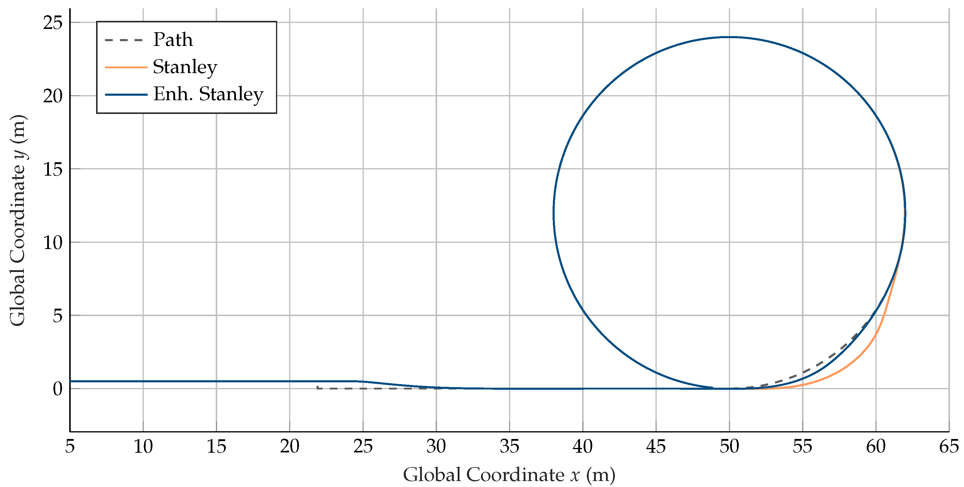
Figure 8 shows the course of the vehicle position and the reference path for the two controller approaches during the step-steer maneuver with 8 m/s. During straight-line driving and the lateral step, the courses of the two controller approaches are identical since, at constant curvature, the two approaches do not differ. After the transition to circular motion, differences appear in the course of the steering angle
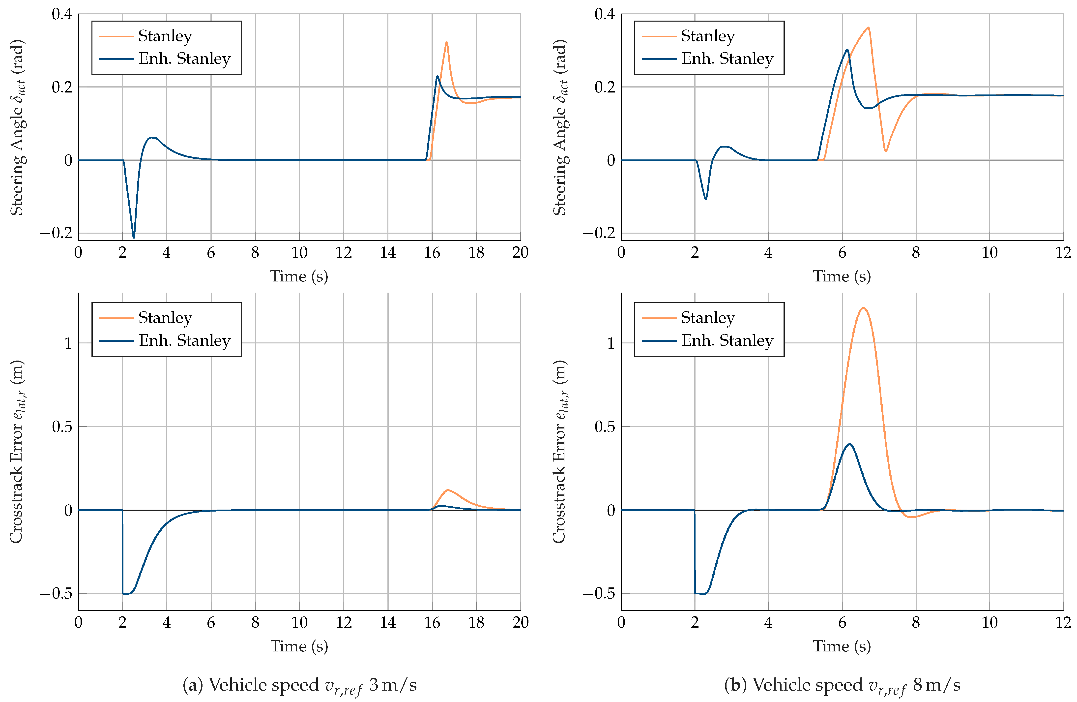
and consequently also in the vehicle position and the cross-track error
as shown in
Figure 9b.
When using the Stanley approach, a deviation of 1.21 m occurs as a result of the transition to circular motion since steering into the circle is conducted too late. The deviation induced leads to further oscillations, which do not fade until half of the circular path has been completed. With the enhanced Stanley approach, overshooting also occurs, but it is smaller (0.39 m) and does not lead to oscillation. In the second half of the circle, the resulting paths of the two approaches are again congruent. The results confirm the desired functionality of the enhanced Stanley approach. With the enhanced approach, the vehicle follows the given path more precisely during changes in curvature. The maneuver presented here includes a step in the curvature and, thus, in the expected yaw rate at the transition to circular motion. The yaw rate of a vehicle, however, cannot change immediately due to rotational inertia and limited tire forces. Therefore the considered maneuver represents a corner case, which, however, allows us to show the limits of both approaches.
The courses of the actual steering angle
and the cross-track error
for the test run with 3 m/s are shown in
Figure 9a. The resulting maximum cross-track errors after the transition to circular motion occur to a smaller extent than for the test run with 8 m/s, and again the maximum deviation using the enhanced Stanley approach is smaller (0.02 m) than for the original Stanley approach (0.12 m). The dependency of the maximum deviation on the velocity is obvious since the vehicle with increasing velocity drives straight a longer distance during the delay time before the measured deviation can lead to a vehicle reaction.
3.2.2. Circuit Maneuver
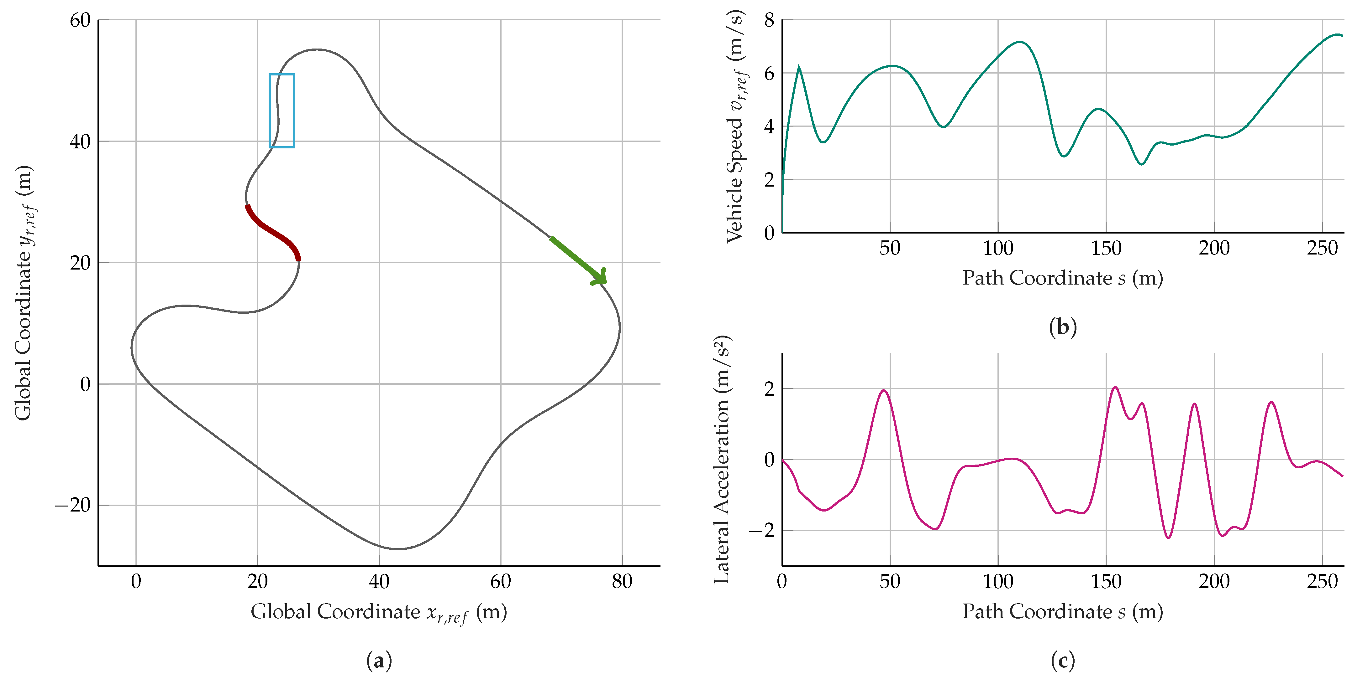
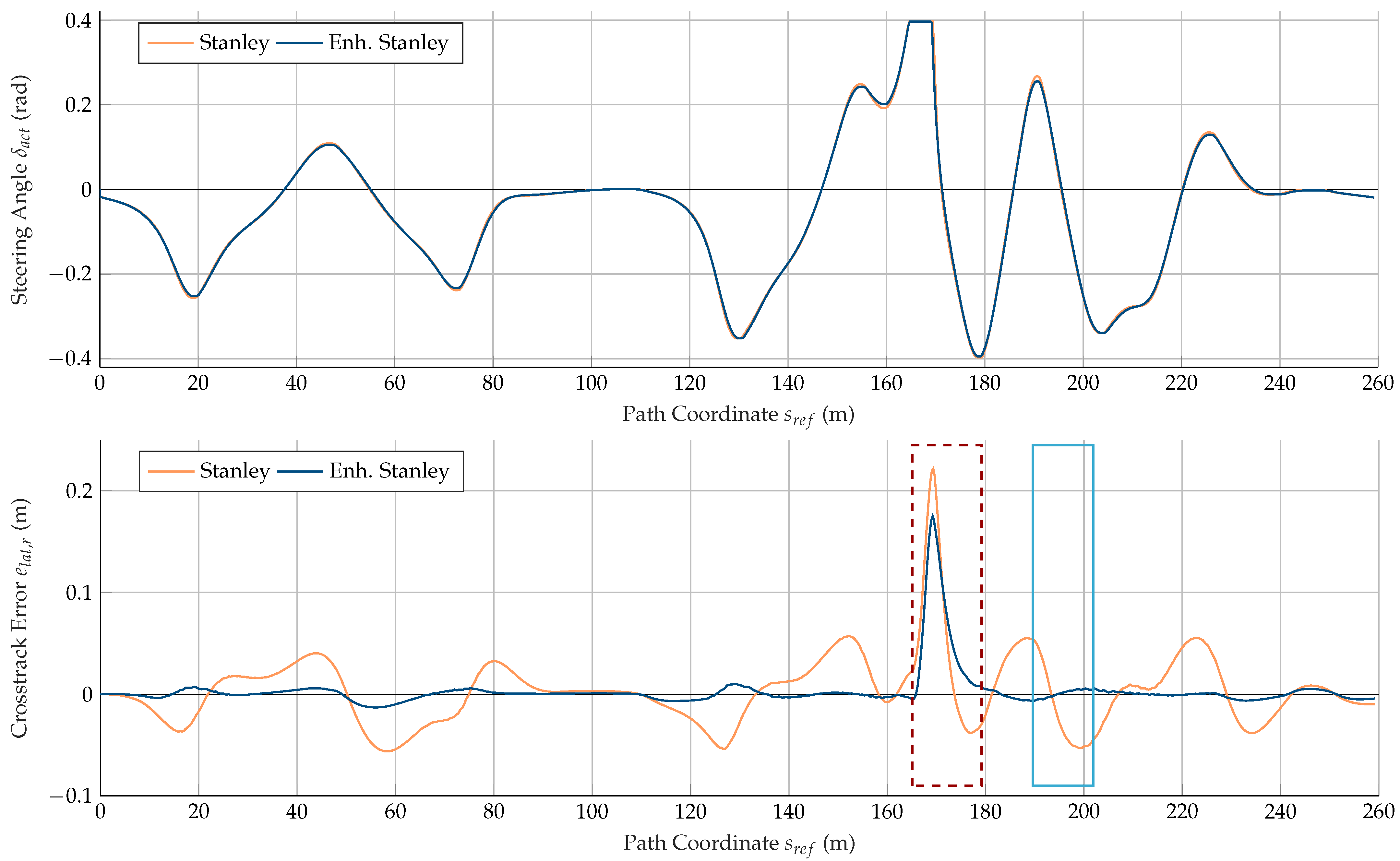
The results of the step-steer maneuver are also confirmed in the dynamic circuit maneuver. The course of the cross-track error of both controller approaches in
Figure 10 shows that the enhanced Stanley approach leads to smaller deviations over the entire round of the circuit. The evaluation of the metrics (
Table 4) yields a maximum cross-track error
of 0.013 m, which corresponds to a reduction of 77% compared to the Stanley approach (0.058 m). The root-mean-square cross-track error
is also reduced from 0.028 m to 0.004 m (−86%).
3.3. Demonstrator Vehicle Validation Results and Summary
To validate the simulated results,
Figure 11 shows the course of the cross-track error on the circuit from the test runs with the real demonstrator vehicle. For the two controller approaches, the results are qualitatively comparable with the simulation results. However, the absolute cross-track errors are larger on the real vehicle. Using the Stanley approach, the maximum cross-track error
is 0.262 m and the root-mean-square cross-track error
is 0.106 m and, thus, both metrics are about four times as large as in the simulation (
Table 4). This is due to the different values obtained from the parameter tuning in the simulation compared to the demonstrator vehicle tests. By using a smaller value for
k, cross-track errors on the real vehicle are corrected using smaller steering angle adjustments than in the simulation, resulting in larger deviations.
As in the simulation, the enhanced Stanley approach also leads to a reduction in the deviations for the real demonstrator vehicle, with the maximum cross-track error
decreasing by 68% to 0.084 m, and the root mean square cross-track error
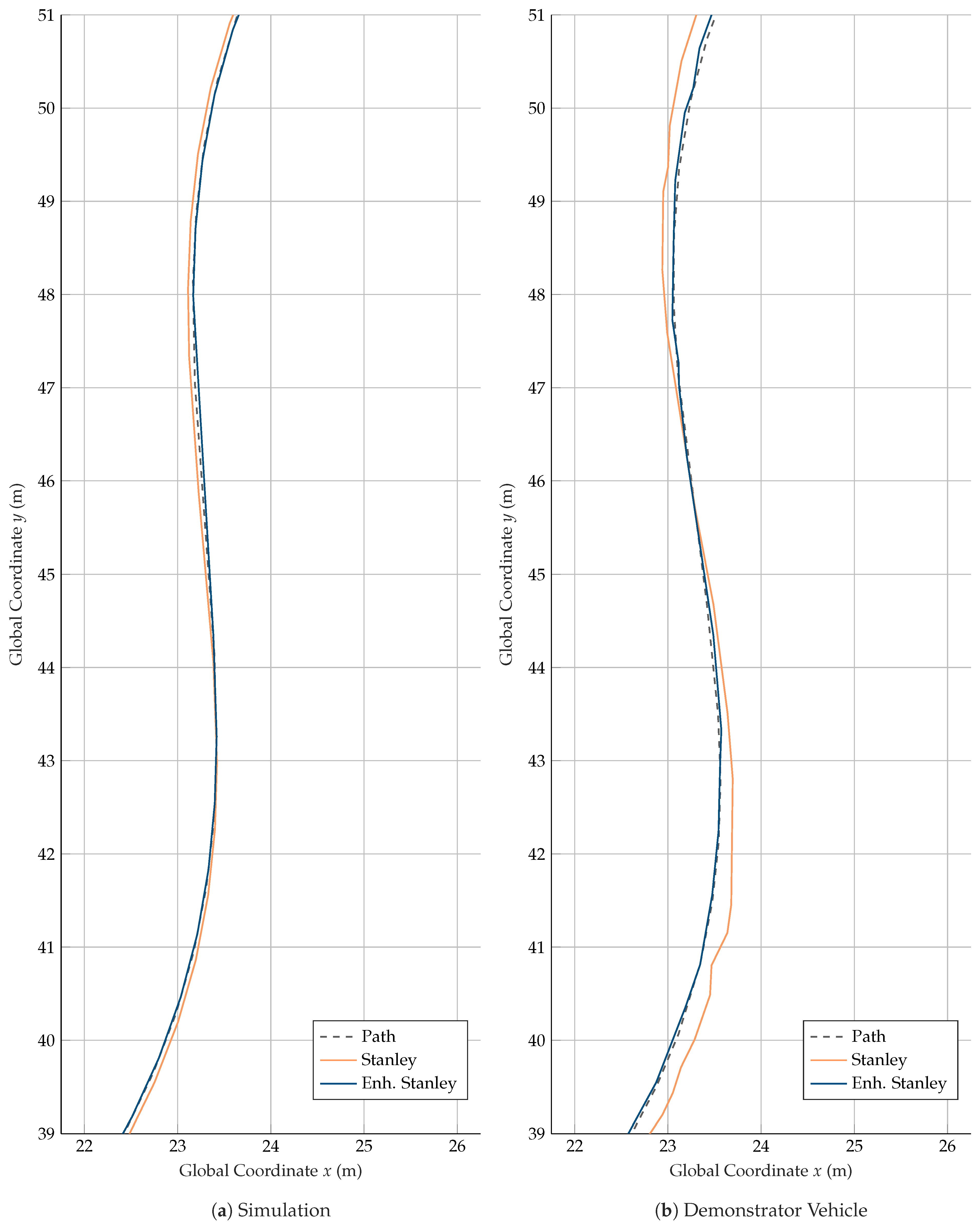
decreasing by 69% to 0.033 m. The improvement due to the enhanced approach is also clearly shown in
Figure 12, where the same map segment of the simulated result and the real vehicle tests are compared. The course of the position, when using the Stanley approach, follows the path with a deviation that is on the outside of the curve. Using the enhanced Stanley approach, the course follows the nominal path with only minor deviations, partly on the outer and inner sides of the curve.
In summary, the described results demonstrate the improvement of the tracking accuracy of the Stanley approach by the proposed enhancement. This was the primary objective of this work. A comparison of the presented approach with other control approaches has been omitted since it was not the authors’ claim to achieve a better control performance than other state-of-the-art approaches. Rather, the focus was to demonstrate the significant effective improvement of the Stanley controller through a relatively minor modification. This is significant since the control approach is widely used because of its well-known simplicity, efficiency, and robustness.
The fields of application of the Stanley controller are moderate velocities and moderate vehicle dynamics, as indicated by the references [
7,
8,
9,
10] cited in the Introduction section. The proposed approach enhances the control performance by predictive feedforwarding the steering angle based on the path curvature. When the path curvature changes continuously, the feedforward component of the enhanced Stanley controller ensures that the resulting steering angle input matches the current path curvature better than it does with the original Stanley controller. This eliminates or reduces deviations from the path that would otherwise occur due to system delay. As a result, the control approach with predictive feedforward requires less control action to compensate for deviations, thus improving the robustness of the approach. At constant curvature, the controller dynamics of the proposed approach are identical to that of the Stanley controller (see
Section 2.4.4). Therefore, it can be assumed that the fields of application in terms of driving dynamics and velocity of the controller remain unchanged by the enhancement and that the advantage is, therefore, mainly related to the increase in control accuracy.
To achieve robust behavior over the entire velocity range of the application, appropriate control parameters must be chosen. In none of the driving situations considered in our study, neither in the simulation nor in the driving tests with the demonstrator vehicle, did unstable behavior occur with either the Stanley or the proposed control method. This indicates that the approach we have chosen to identify suitable controller parameters is effective; however, no statement about the limits of stability at higher velocity can be made from this as the velocity of the investigated maneuvers was limited due to the vehicle’s maximum velocity of 8 m/s.
4. Conclusions and Outlook
We have proposed an enhancement to the Stanley path tracking controller that improves its tracking accuracy by mitigating the disturbing effects of system delay. We first reformulated the Stanley approach so that the reference path curvature appears explicitly in the equation. While the reference values of all other path inputs are read from the point on the path closest to the vehicle’s reference point, we chose a point on the path that is offset by the feedforward distance along the path to read the path curvature input. For the feedforward distance, we have chosen the distance that the vehicle travels at the current velocity during the constant specified feedforward time. The approach is designed pragmatically to avoid additional effort for implementation and application on a vehicle in order to retain one of the key advantages of the Stanley path-tracking controller approach. Nevertheless, the enhancement resulted in a significant reduction in cross-track error metrics. We have demonstrated this in this article both in the simulative study and with the real demonstrator vehicle.
With our solution, we address applications with moderate velocities and moderate vehicle dynamics on vehicles with sensors and steering systems affected by delays. By improving accuracy despite system delay with low computational cost, we provide a path-tracking solution that can contribute to the realization of economical, automated vehicle systems based on low-cost components. With the same input and output sizes as the Stanley controller, our solution can also be used as an easy-to-implement upgrade for existing applications using a Stanley controller without requiring structural changes or increased complexity.
In further investigations, the approach should be tested at higher velocities and, thus, more dynamic driving maneuvers to determine the limitations of the proposed controller. This requires the implementation of the device on a vehicle that allows higher velocities than the demonstrator vehicle used. Further insight can be gained by comparing the control performance of the proposed approach with the performance of other approaches, especially more complex approaches.
