Article

Development of a PHEV Hybrid Transmission for Low-End MPVs Based on AMT

1
School of Automotive Studies, Tongji University, No. 4800 Cao’an Road, Jiading District, Shanghai 201804, China
2
Institute for Mechatronic Systems in Mechanical Engineering, Technische Universität Darmstadt, Otto-Berndt-Straße 2, L101/208, 64287 Darmstadt, Germany
*
Authors to whom correspondence should be addressed.
Vehicles 2020, 2(2), 236-248; https://doi.org/10.3390/vehicles2020013
Submission received: 27 December 2019 / Revised: 14 March 2020 / Accepted: 19 March 2020 / Published: 25 March 2020
(This article belongs to the Special Issue Future Powertrain Technologies)

Abstract

:
In order to improve the fuel economy of vehicles, based on the automated mechanical transmission (AMT), a plug-in hybrid electric vehicle (PHEV) hybrid transmission for low-end multi-purpose vehicles (MPVs) is developed. To obtain the statistics of the best-selling models, we took several best-selling models in the Chinese market as the research object to study the relationship between power demand, energy demand, weight, and cost. The power requirements and energy requirements of PHEVs are decoupled. According to the decoupled theory, a single-motor parallel scheme based on the AMT is adopted to develop a PHEV hybrid transmission. In the distribution of engine and motor power, the engine just needs to meet the vehicle’s constant driving power, and the backup power can be provided by the motor, which means we can use an engine with a smaller power rating. The energy of short-distance travel is mainly provided by the motor, which can make full use of the battery, reducing the fuel consumption. The energy of long-distance travel is mainly provided by the engine, which can reduce the need for battery capacity. The working modes of the electrified mechanical transmission (EMT) are proposed, using P3 as the basic working mode and setting the P2 mode at the same time, and the gear ratios are designed. Based on the above basic scheme, two rounds of prototype development and assembling prototype vehicles for testing are carried out for the front-engine-front-drive (FF) layout. The test results show that the vehicle’s economy has been improved compared to the unmodified vehicle, and the fuel-saving rate of 100 kilometers has been achieved at 35.18%. The prototype development and the vehicle matching verify the effectiveness of the new configuration based on AMT.

1. Introduction

Environmental pollution and energy shortage in the world urgently require the development of new energy vehicles, which has become the world consensus [1,2]. As two important types of new energy vehicles, electric vehicles (EVs) and plug-in hybrid electric vehicles (PHEVs) have become the main research directions of new energy vehicles in the world [3,4]. PHEVs can completely solve the user’s mileage anxiety problem, and become one of the main choices of users [5,6].
The dedicated hybrid transmission (DHT) is the most important component of the PHEV’s powertrain, which couples the engine and the motor [7]. According to the different power coupling forms, DHTs can be divided into series, parallel, and power-split configurations [8]. The series DHT can only be used on extended-range electric vehicles, such as Chevrolet Volt, BMW i3, Nissan Note e-power, etc. However, it cannot drive the vehicle directly by engine. The engine power must be converted into electric energy to drive the vehicle [9,10]. The parallel DHT couples the engine power and the motor power in parallel, enabling two powers to drive the vehicle individually or together. Typical parallel DHTs include Volkswagen’s single-motor dual-clutch transmission and BYD’s DM-II transmission [11,12]. The power-split DHT enables more flexible coupling between the engine and the motor, allowing the vehicle to combine the advantages of both series and parallel [13,14], with better fuel economy, such as Toyota’s Prius, the GM’s VOLTEC II, and so on [15,16,17]. However, the structure of the power-split DHT is complex, with two sets of motors and motor controllers, which greatly increases the cost of the transmission. Another scheme is on the basis of the automated mechanical transmission (AMT), such as BYD’s DM, the Eaton’s hybrid system, and so on [18,19]. Compared with the power-split DHT, the AMT-based solution has a simpler structure and a lower cost, meaning that it is more suitable for developing a PHEV low-cost hybrid transmission.
Based on the above design ideas, a new hybrid transmission based on AMT is proposed in this paper. We have developed prototypes, assembled prototype vehicles, and conducted tests to verify the effectiveness of the scheme.

2. Statistical Law of New Energy Vehicles

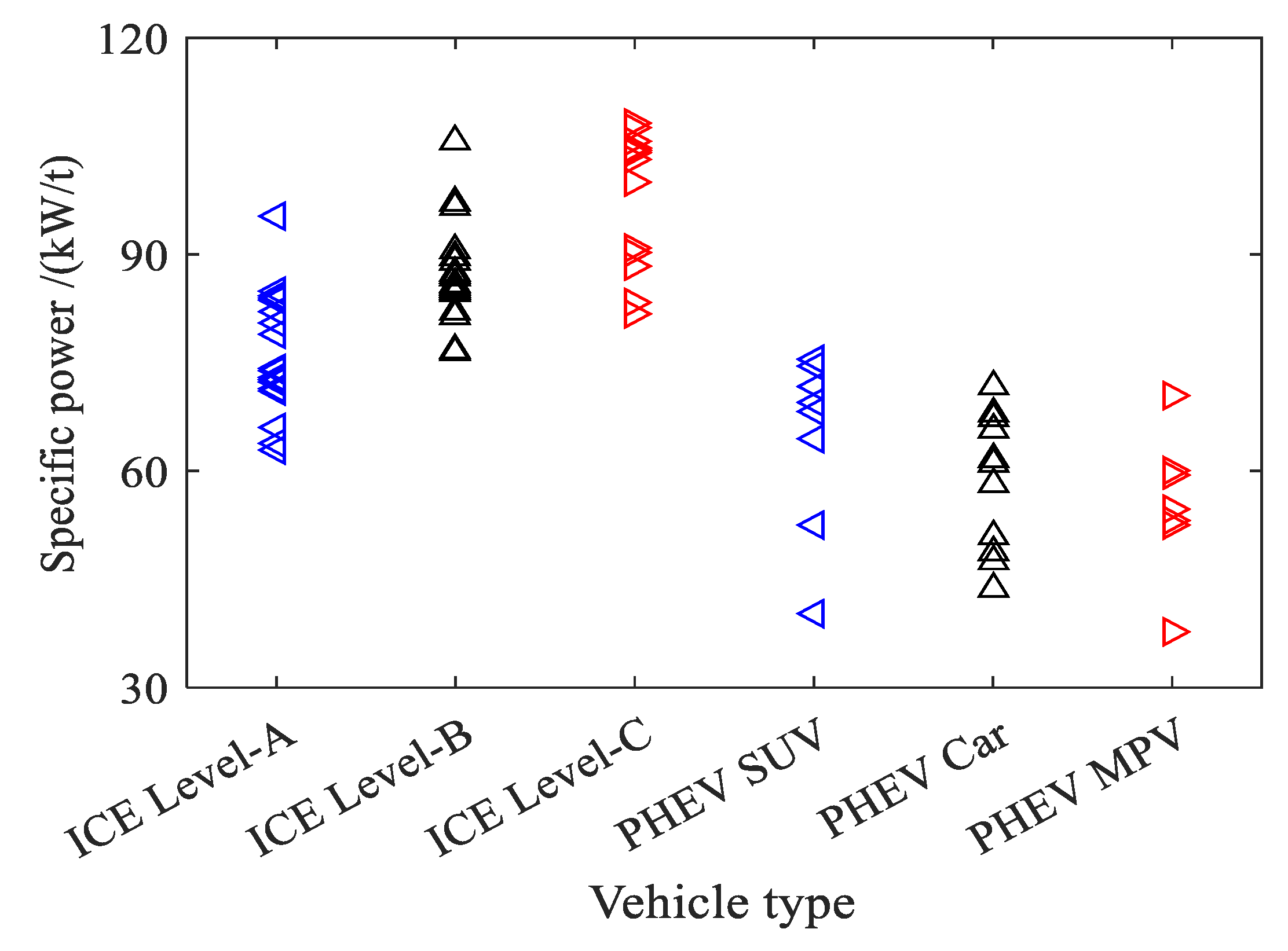
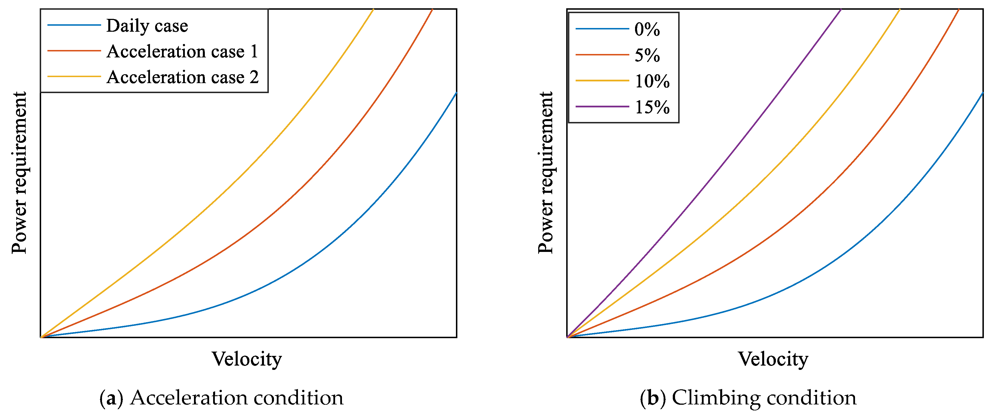
2.1. PHEV Power Demand

The best-selling 58 internal combustion engine vehicles (ICEVs) and 30 PHEVs (Statistics for the first 6 months of 2019) are statistically analyzed. All statistics are from two statistics websites, Autohome (http://www.autohome.com.cn/) and Yiche.com (http://bitauto.com/). The statistical results of engine specific power are shown in Figure 1. In the figure, SUV is short for sport utility vehicle, and MPV is short for multi-purpose vehicle.
According to Figure 1, the engine specific power of the PHEVs is significantly lower than that of the ICEVs. The maximum engine specific power of the PHEV MPVs is 70.4 kW/t, the minimum is 37.6 kW/t, and the median is 54 kW/t.
The required power of ICEVs under all conditions is only provided by the engine. This includes the constant driving power at constant speed required to overcome rolling resistance and air resistance, as well as the backup power required for acceleration and climbing. For acceleration and climbing conditions, the vehicle’s power requirements are shown in Figure 2.
In Figure 2a, the three curves represent three different acceleration situations. In Figure 2b, the four curves in the figure represent the power requirements of the four different slopes (0%, 5%, 10%, 15%).
According to Figure 1 and Figure 2, the required power of the vehicle can be divided into two parts: the constant driving power and the backup power. The constant driving power and backup power of ICEVs can only be provided by the engine. But the PHEV engine only needs to meet the constant driving power demand. Hence, the engine specific power of PHEVs is significantly lower than that of ICEVs. When the vehicle requires a large backup power, the engine and the motor drive the vehicle together. Therefore, it can be considered that the backup power of PHEVs can be provided by the motor.

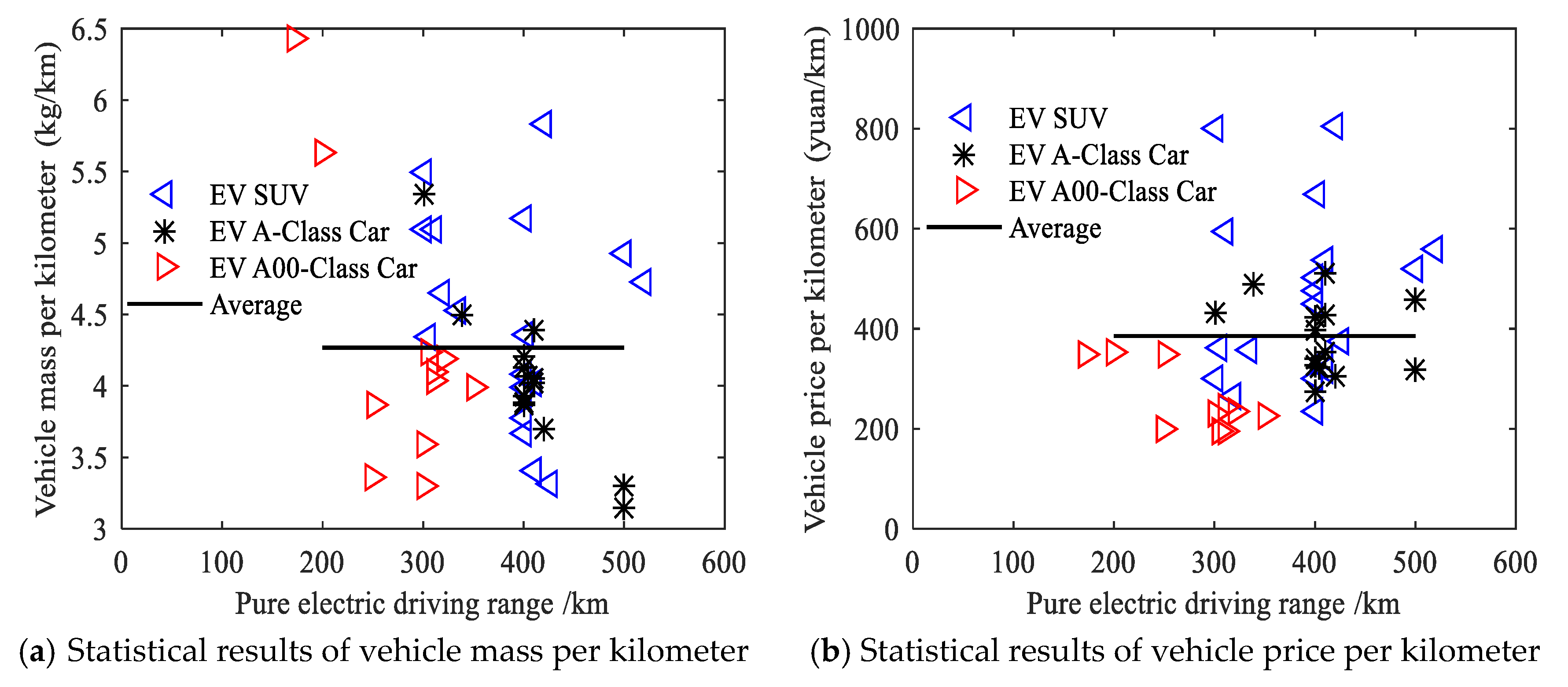
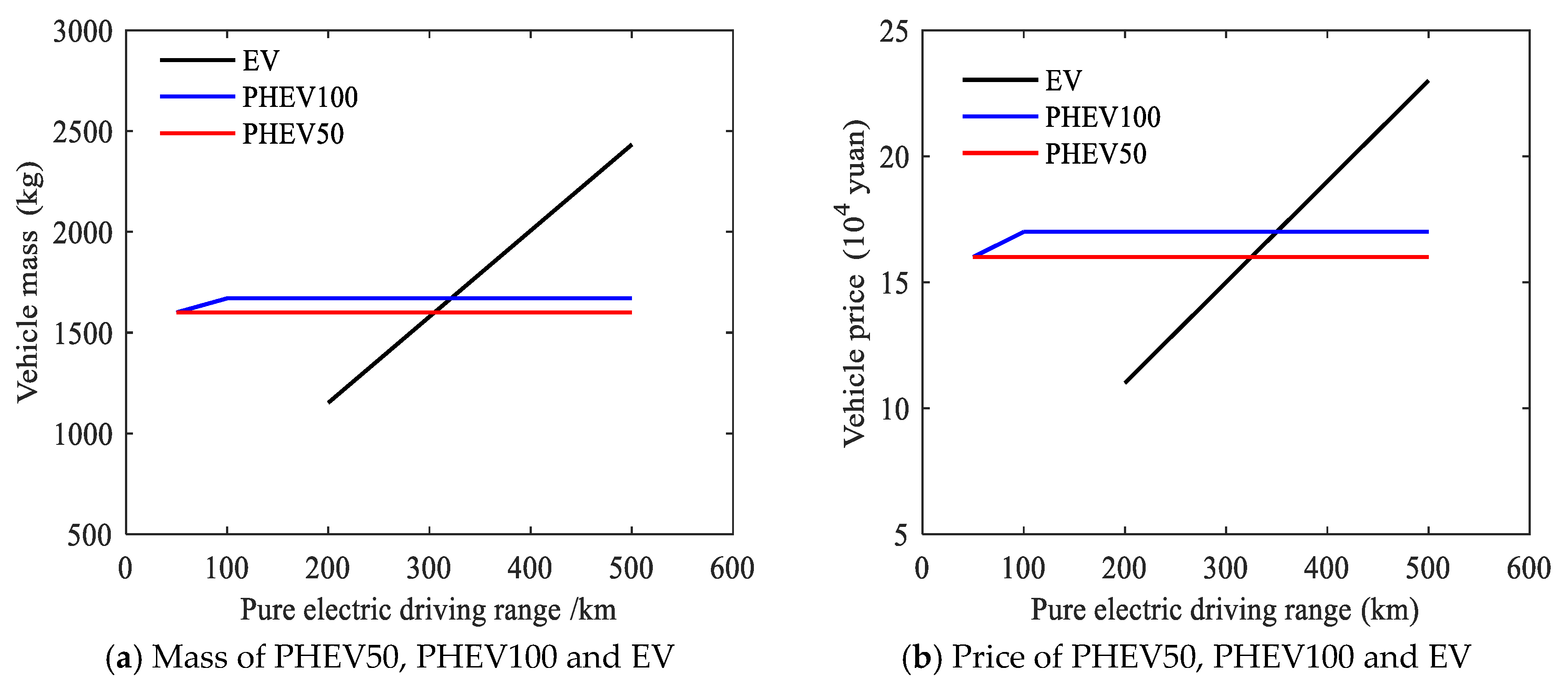
2.2. PHEV Energy Demand and Cost Analysis

China currently has no official data on the daily mileage statistics. According to the National Household Travel Survey (NHTS) of 2009 in America, approximately 90% of car commuters in the U.S. travel less than 30 miles to work. That is, if the pure electric driving range of PHEVs is set to 50 km, it can meet the commuting needs of about 90% of users.
The best-selling 54 electric vehicles (EVs) are statistically analyzed. The statistical results of vehicle mass and price per kilometer are shown in Figure 3.
According to Figure 3, under the current technology and market conditions, the pure electric driving range of the best-selling EVs is increased by 1 km, the price increases by about 400 yuan, and the mass increases by about 4.27 kg. The price of 20 best-selling A-class PHEVs in China with a pure electric driving range of 50–60 km is statistically analyzed, and the average price is about 160,000 yuan. The average price of the A class PHEV50s (short for, the PHEVs with a pure electric driving range of 50 km) is 160,000 yuan, which is increased by 400 yuan per kilometer. The average mass of the A-Class PHEV50s is 1600 kg, which is increased by 4.27 kg per kilometer. The price of PHEV50, PHEV100 (short for, the PHEVs with a pure electric driving range of 100 km) and EV are compared and analyzed. The results are shown in Figure 4.
As can be seen from Figure 4, the mass intersection point of EV and PHEV50 is 315 km, and the price intersection point of EV and PHEV50 is 325 km. That is, if the pure electric driving range of EVs is more than 325 km, the mass and price of EVs will exceed PHEV50s. This means that EVs that pursue long driving ranges have no advantage in terms of cost.
In summary, with the increase in driving mileage, the weight of the vehicle will also increase. Increasing the quality of the car will increase the energy consumption of the car and increase the useless power of the car, which will lead to the deterioration of the vehicle’s economy. So, it is difficult to find a suitable demarcation point to meet both short-distance travel and long-distance travel for EV, but PHEVs solve this problem very well. If the pure electric driving range of PHEVs is set to 50 km, it can meet the commuting needs of about 90% of users. Therefore, this paper proposes a solution based on AMT for PHEVs. We use a decoupled approach to consider power requirements and energy requirements. In the distribution of engine and motor power, the engine just needs to meet the vehicle constant driving power, and the backup power can be provided by the motor, which means we can use an engine with a smaller power rating. When driving long distances, the engine provides backup energy, which greatly reduces the need for battery capacity.

3. Configuration and Parameter Design of PHEV Hybrid Transmission Based on AMT

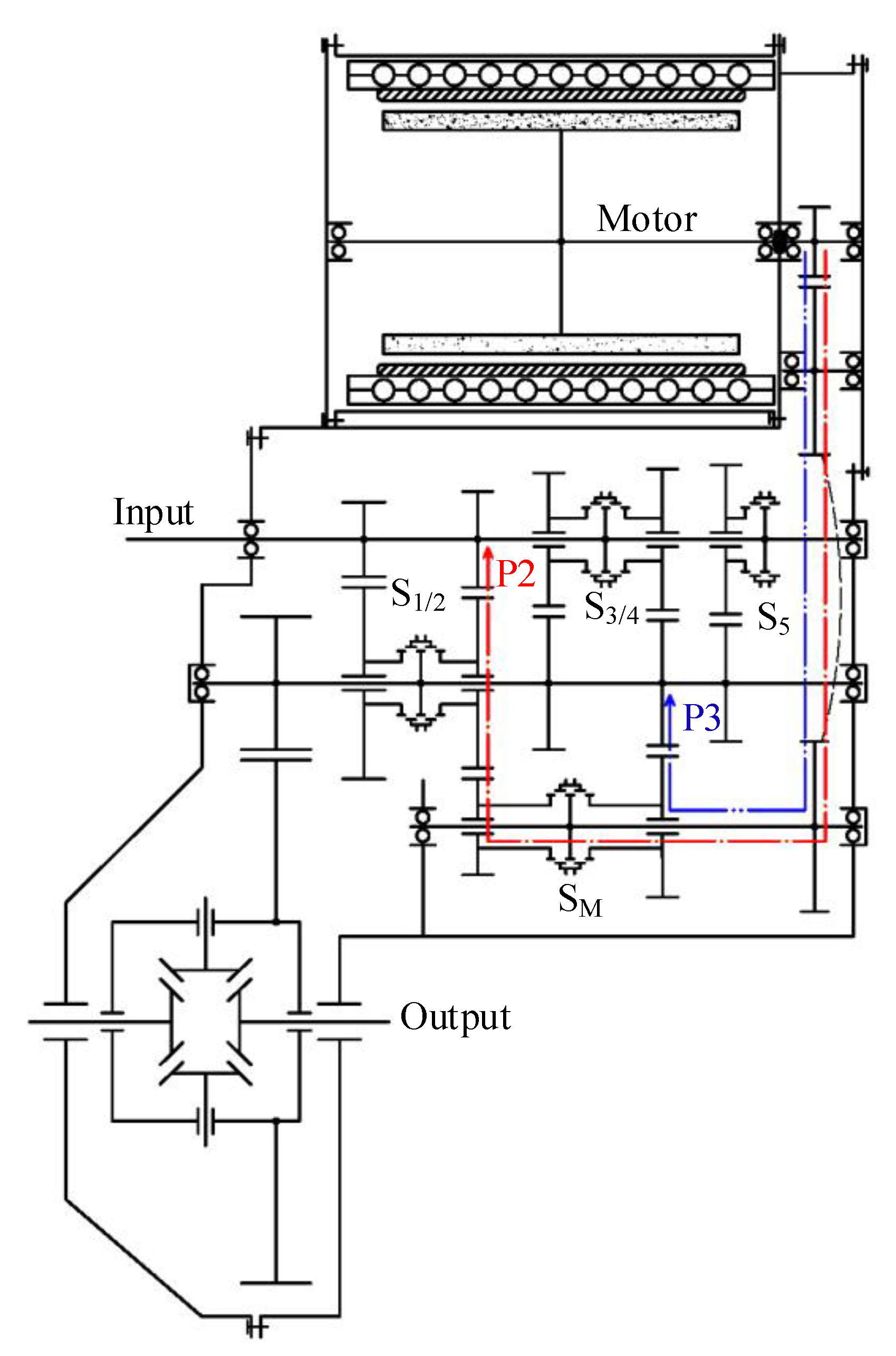
3.1. Transmission Configuration

Based on the AMT, an electrified mechanical transmission (EMT) is developed for PHEVs, and its configuration is shown in Figure 5. In the figure, S1/2, S3/4, and S5 are the synchronizers of first/second, third/fourth, and fifth gears of mechanical gears. S M is the synchronizer of the mode gears. P2 and P3 are the coupling paths of the electric power flow to the input shaft and the output shaft of the transmission, respectively. P2 indicates that the drive motor is located behind the engine and before the transmission and is connected to the transmission input. That is, the power output of the motor and the engine is coupled at the transmission input. P3 indicates that the drive motor is connected to the transmission output in some way. That is, the motor output power and the engine is coupled at the output of the transmission.
The main technical features of EMT are as follows:
  • Based on fixed axis gears and AMT technology, the industrialization foundation is good.
  • Both P2 and P3 modes are considered, and the functions are complete.
  • There is no power interruption during shifting in P3 mode.
  • Multiple gears can make the engine more efficient.
  • Multiple gears can improve the power density and torque density of the motor.

3.2. Working Modes

The main working modes are shown in Table 1.

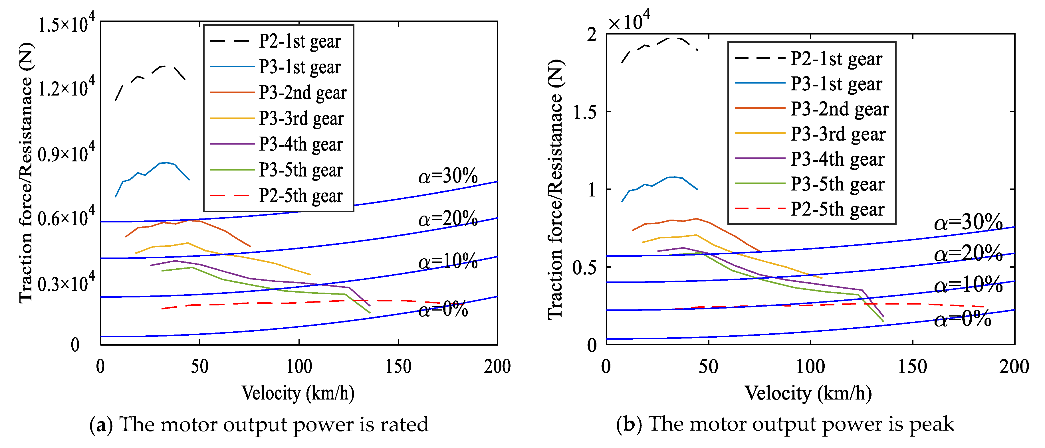
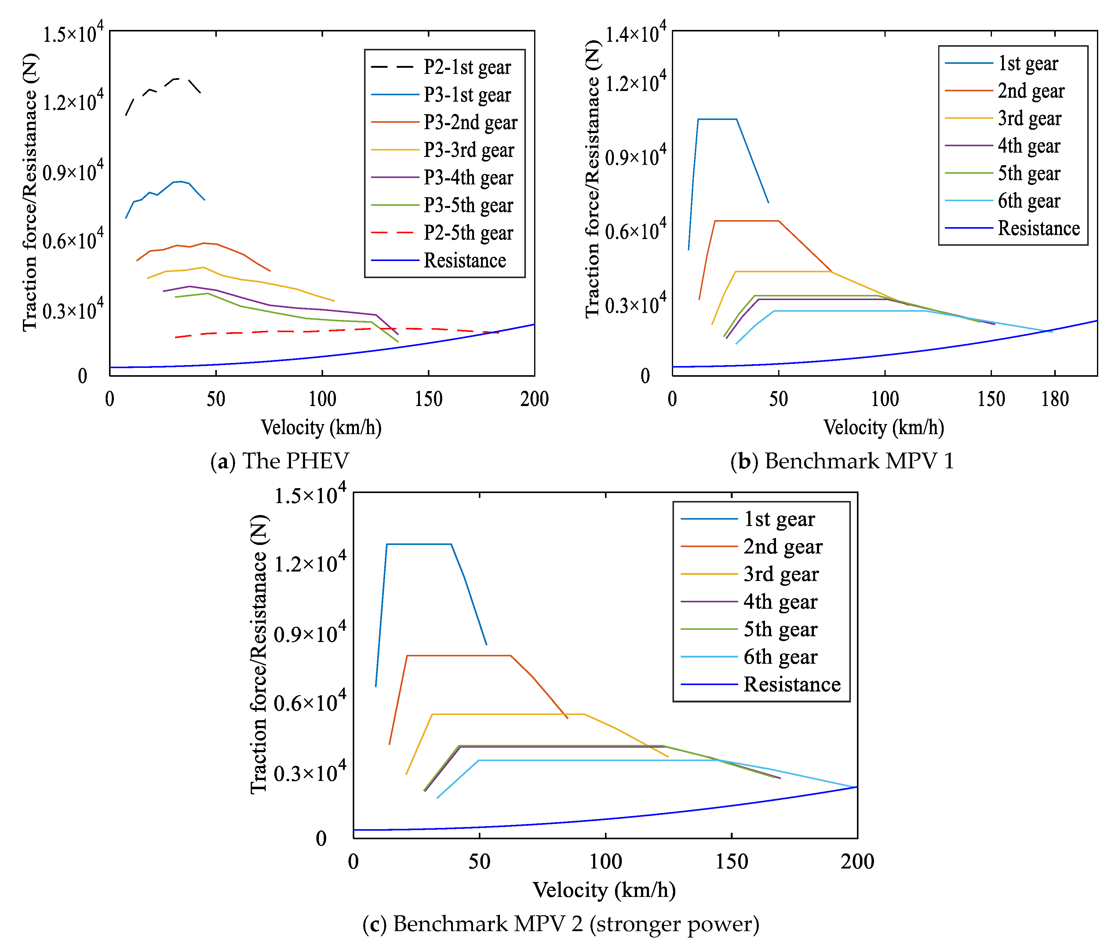
3.3. Gear Ratio Design

On the basis of an MPV, a PHEV equipped with the EMT is developed. According to the results of Section 2, the engine specific power is selected as 54 kW/t. The vehicle mass is set to 1500 kg. The calculated engine power is 81 kW, and the engine power actually selected is 77 kW. The rated power of the motor is 35 kW, and the peak power is 70 kW.
The design criteria of the gear ratio, i.e., the constraints of the gear ratio, are as follows:
  • The mechanical gear ratio design takes into account both pure mechanical driving and hybrid driving.
  • The center distances of the coupling shaft and the output shaft in P2 and P3 modes are the same.
  • The motor is as close as possible to the transmission.
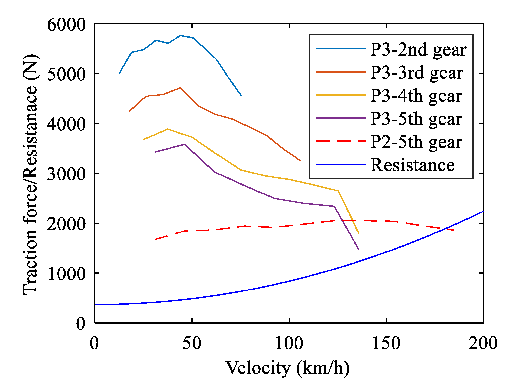
  • The second/third/fourth/fifth gears in the P3 mode meet daily driving needs.
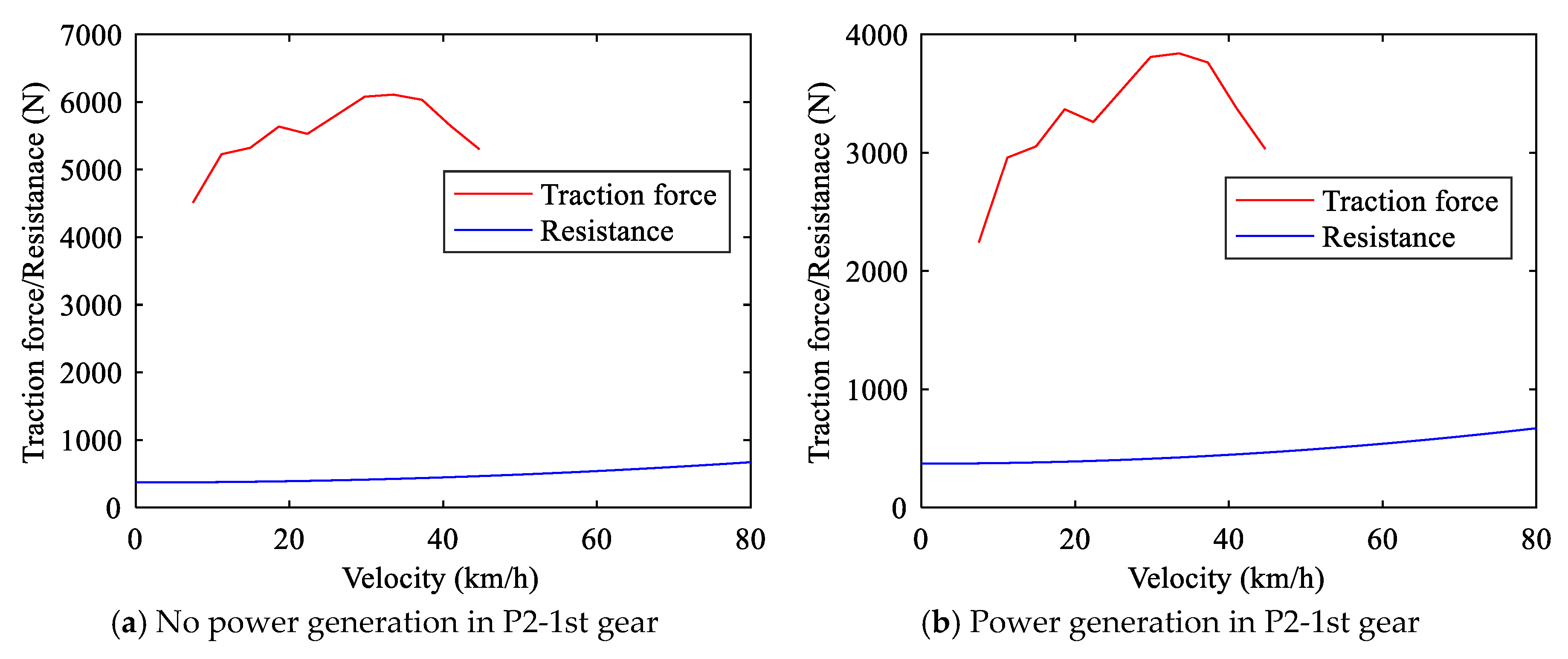
  • The first gear in the P2 and P3 modes meet extreme conditions, such as maximum climbing.
According to the above criteria, the design results of the gear ratio are shown in Table 2.
Under the urban conditions, when the PHEV works in EV mode with the P3 mode, the traction force and resistance curves are shown in Figure 6.
Under the urban conditions, when the PHEV works in HEV mode with the P3 mode and second/third/fourth/fifth gear. Under the extra-urban conditions, the PHEV works in HEV mode with the P3/P2 mode, and the traction force and resistance curves are shown in Figure 7. As can be seen from Figure 7, the maximum velocity can be 180 km/h.
Under the limp mode, the PHEV works in HEV mode with the P2 mode and first gear, and the traction force and resistance curves are shown in Figure 8.
In the climbing condition, under different slopes, the traction force and resistance curves with HEV mode are shown in Figure 8. As can be seen from Figure 9, the vehicle can easily drive up a 30% slope.
The dynamic performance comparison between the PHEV and the benchmark vehicles is shown in Figure 10. As can be seen from Figure 10, the PHEV is powerful.

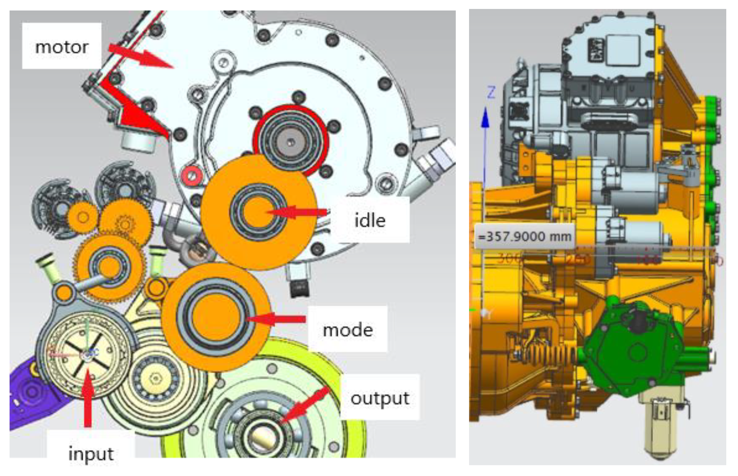
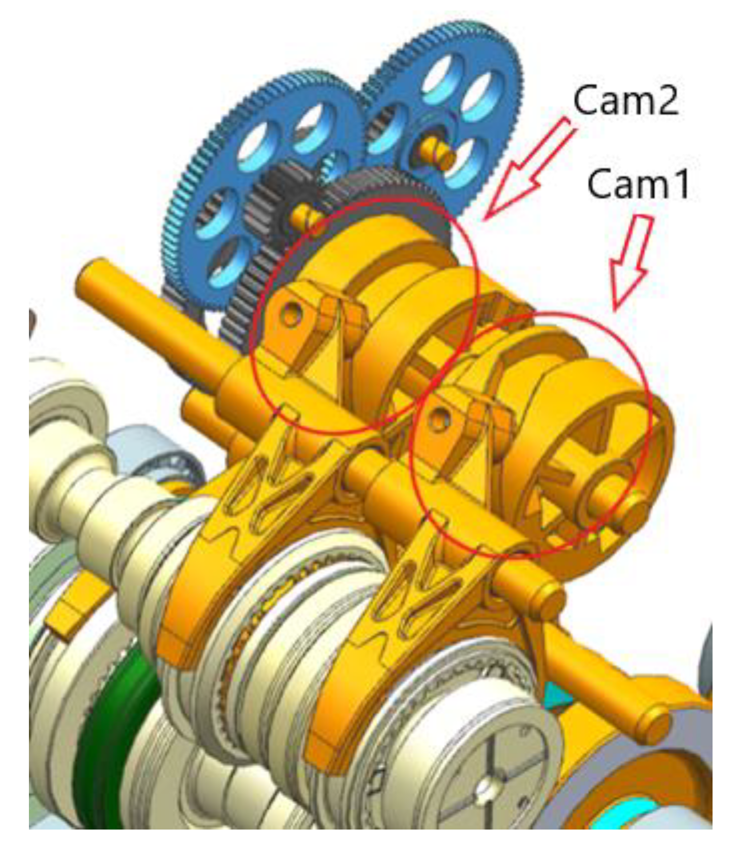
4. Prototyping and Verification

Based on the above basic scheme, two rounds of prototype development and assembling prototype vehicles for testing are carried out for the front-engine-front-drive (FF) layout.

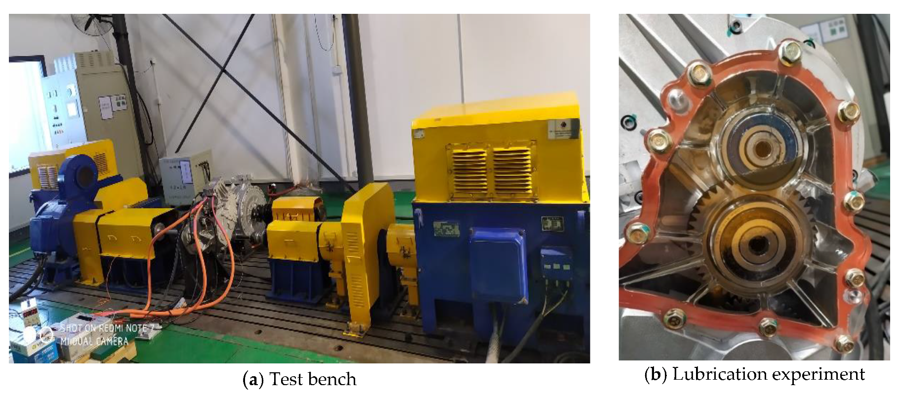
4.1. EMT prototyping

According to the above scheme and parameter design results, the EMT prototype is developed as shown in Figure 11.
The shift actuator is shown in Figure 12. Cam 2 is responsible for the P2 and P3 mode switching, and cam 1 is responsible for gear shifting.
We designed the EMT transmission based on AMT. The addition of the motor power coupling shaft and the motor power switching synchronizer made EMT have a variety of different working modes (P2 and P3). Subsequently, the EMT assembly was parameterized, including the selection of power system components and the optimal speed ratio configuration of the transmission system. Finally, the vehicle’s dynamics and economy are analyzed using the parameters of the project as the standard.

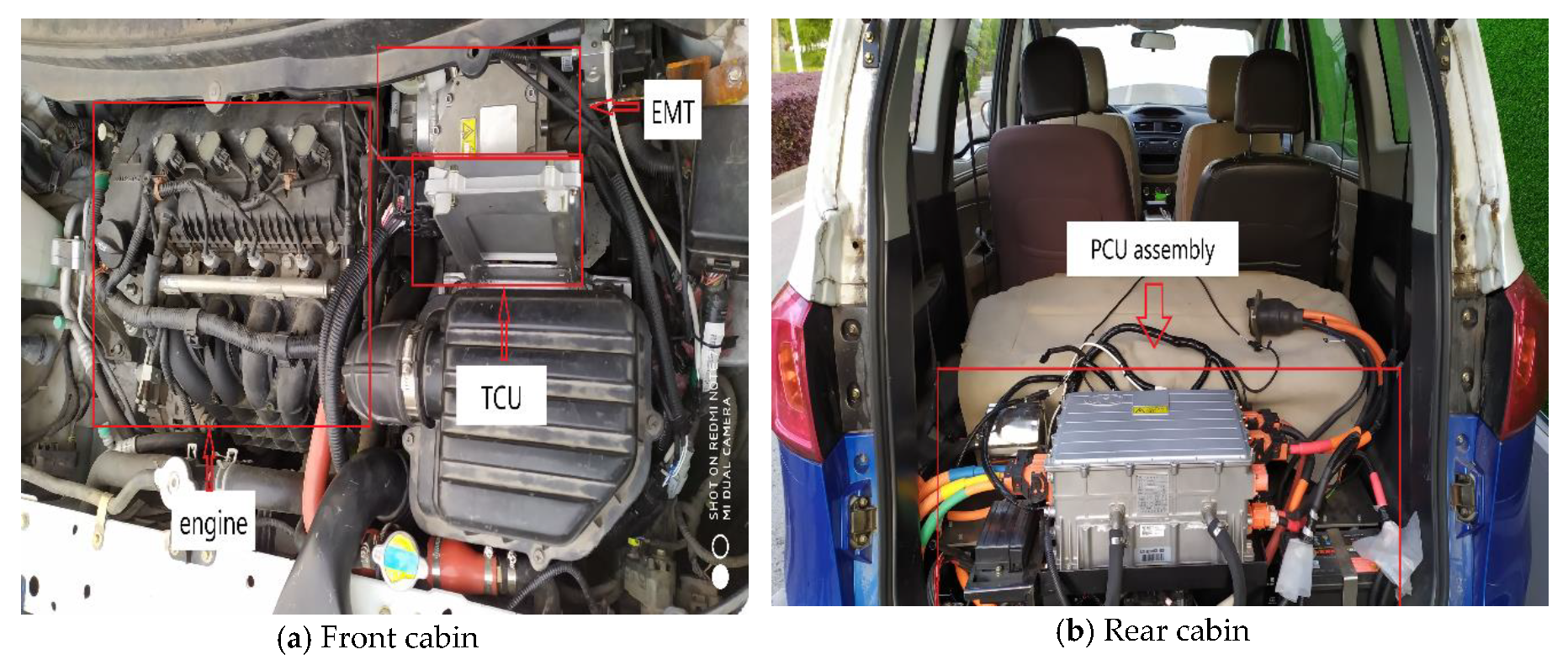
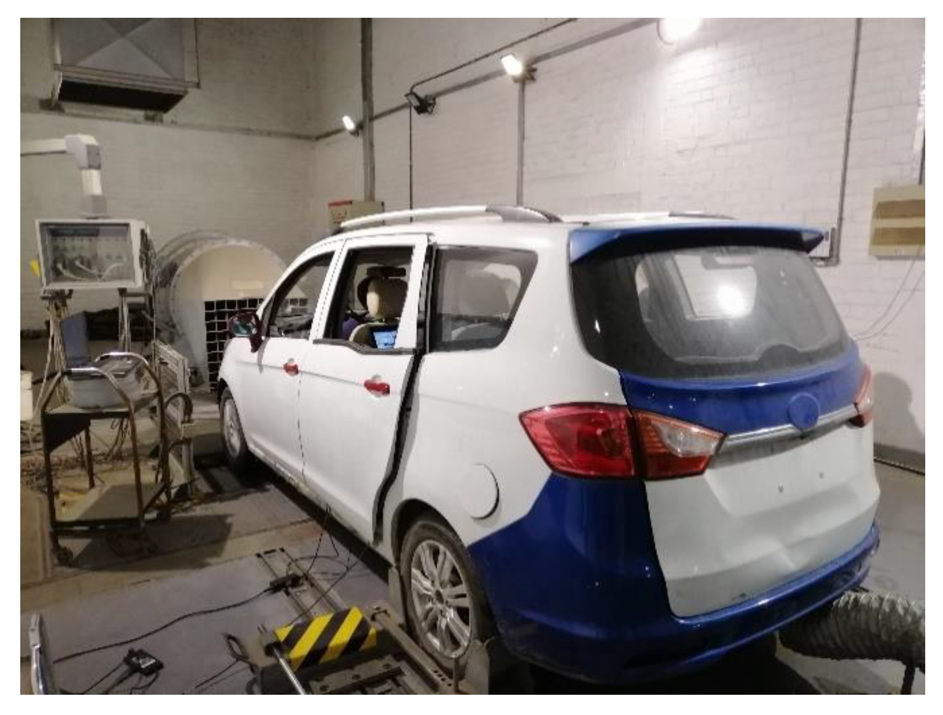
4.2. EMT and Vehicle Test

In order to verify the actual performance of EMT, we conducted a bench test in accordance with national standards.
As can be seen from Figure 13, we individually test the overall efficiency, lubrication, shift performance, and durability of the EMT. To observe the lubrication of the gearbox, we made a transparent front cover especially.
As can be seen from Figure 14, we have selected a representative MPV for modification. We retained the engine of the original car, replaced the transmission with EMT, and added a three-electric system. This vehicle is an FF layout, so the EMT assembly is arranged in the front cabin. The PCU assembly and other accessories are installed in the rear cabin.
As can been seen in Figure 15, we tested the power and economy of the prototype on the chassis dynamometer. For vehicle dynamics, we tested the vehicle’s 100-km acceleration time, maximum speed, etc. For the economy of the vehicle, we mainly tested the New European Driving Cycle (NEDC) fuel consumption of the vehicle to calculate the equivalent fuel consumption of 100 km.
The test results are shown in Table 3. The results show that the EMT can simultaneously meet the dynamic and economic requirements of PHEVs. The prototype development and the vehicle matching verify the effectiveness and practicability of the new configuration based on AMT.
Because we did not modify the engine, the comparison of vehicle dynamics is not meaningful. So, we only conducted economic tests on unmodified cars. Compared with the experimental results of unmodified vehicles, it is found that the vehicle’s power and economy have been improved, and the fuel-saving rate of 100 km has been achieved at 35.18% ((8.30 − 5.38)/8.30 ≈ 0.3518) (Table 4). The prototype’s dynamic and economical tests validate the design’s effectiveness.

5. Conclusions

Based on the AMT, a PHEV hybrid transmission for low-end MPVs is developed. The parameter design and prototype development are carried out, and the following conclusions are obtained:
  • The power demand and energy demand of PHEVs can be decoupled. In the distribution of engine and motor power, the engine just needs to meet the vehicle’s constant driving power, and the backup power can be provided by the motor, which means we can use an engine with a smaller power rating. Compared with EV, PHEV can easily meet the needs of short-distance travel and long-distance travel with a small battery capacity.
  • The scheme is based on the AMT, with a single motor parallel design, using P3 as the basic working mode and setting the P2 mode at the same time. The energy of short-distance travel is mainly provided by the motor, which can make full use of the battery, reducing fuel consumption. The energy of long-distance travel is mainly provided by the engine, which can reduce the need for battery capacity. So, the energy of daily driving is provided by the battery, while the backup energy for long-distance driving is provided by the engine.
  • Compared with the experimental results of unmodified vehicles, it is found that the vehicle’s economy has been improved, and the fuel-saving rate of 100 km has been achieved at 35.18% ((8.30 − 5.38)/8.30 ≈ 0.3518). The prototype’s dynamic and economical tests validate the design’s effectiveness.

Author Contributions

Conceptualization, Z.Z. and S.R.; methodology, Y.Z. and Y.B.; validation, Y.Z. and Y.B.; formal analysis, Y.Z. and Y.B.; writing—original draft preparation, Y.B.; writing—review and editing, S.Z.; funding acquisition, Z.Z. All authors have read and agreed to the published version of the manuscript.

Funding

This research was funded by the National Key Research and Development Project of China (Grant No. 2017YFB0103200).

Conflicts of Interest

The authors declare no conflict of interest.

References

  1. Liu, Z.; Guan, D.; Crawford-Brown, D.; Zhang, Q.; He, K.; Liu, J. A low-carbon road map for China. Nature 2013, 500, 143. [Google Scholar] [CrossRef] [PubMed]
  2. Hao, H.; Ou, X.; Du, J.; Wang, H.; Ouyang, M. China’s electric vehicle subsidy scheme: Rationale and impacts. Energy Policy 2014, 73, 722–732. [Google Scholar] [CrossRef]
  3. Du, J.; Ouyang, M.; Chen, J. Prospects for Chinese electric vehicle technologies in 2016 e 2020: Ambition and rationality. Energy 2020, 120, 584–596. [Google Scholar] [CrossRef]
  4. Wu, G.; Zhang, X.; Dong, Z. Powertrain architectures of electrified vehicles: Review, classification and comparison. J. Frankl. Inst. 2015, 352, 425–448. [Google Scholar]
  5. Markel, T.; Simpson, A. Cost-Benefit Analysis of Plug-In Hybrid Electric Vehicle Technology. World Electr. Veh. J. 2007, 1, 294–301. [Google Scholar] [CrossRef] [Green Version]
  6. Amjad, S.; Neelakrishnan, S.; Rudramoorthy, R. Review of design considerations and technological challenges for successful development and deployment of plug-in hybrid electric vehicles. Renew. Sustain. Energy Rev. 2010, 14, 1104–1110. [Google Scholar] [CrossRef]
  7. Ehsani, M.; Gao, Y.; Miller, J.M. Hybrid Electric Vehicles: Architecture and Motor Drives. Proc. IEEE 2007, 95, 719–728. [Google Scholar] [CrossRef]
  8. Chan, C.C.; Bouscayrol, A.; Chen, K. Electric, Hybrid, and Fuel-Cell Vehicles: Architectures and Modeling. IEEE Trans. Veh. Technol. 2010, 59, 589–598. [Google Scholar] [CrossRef]
  9. Conlon, B.M.; Blohm, T.; Harpster, M.; Holmes, A.; Palardy, M.; Tarnowsky, S.; Zhou, L. The Next Generation “Voltec” Extended Range EV Propulsion System. SAE Int. J. Alt. Power. 2015, 4, 248–259. [Google Scholar] [CrossRef]
  10. Rahman, K.M.; Jurkovic, S.; Stancu, C.; Morgante, J.; Savagian, P.J. Design and Performance of Electrical Propulsion System of Extended Range Electric Vehicle (EREV) Chevrolet Volt. IEEE Trans. Ind. Appl. 2015, 51, 2479–2488. [Google Scholar] [CrossRef]
  11. Jelden, H.; Pelz, N.; Haußmann, H.; Kloft, M. The Plug-in Hybrid Drive of the VW Passat GTE. MTZ Worldw. 2015, 76, 16–23. [Google Scholar] [CrossRef]
  12. Neusser, H.-J.; Jelden, H.; Bühring, K.; Philipp, K. The Powertrain of the Jetta Hybrid from Volkswagen. MTZ Worldw. 2013, 74, 4–11. [Google Scholar] [CrossRef]
  13. Meisel, J. An Analytic Foundation for the Toyota Prius THS-II Powertrain with a Comparison to a Strong Parallel Hybrid-Electric Powertrain. In Proceedings of the SAE 2006 World Congress & Exhibition, Detroit, MI, USA, 3–6 April 2006. [Google Scholar]
  14. Yang, Y.; Hu, X.; Pei, H.; Peng, Z. Comparison of power-split and parallel hybrid powertrain architectures with a single electric machine: Dynamic programming approach. Appl. Energy 2016, 168, 683–690. [Google Scholar] [CrossRef]
  15. Kim, J.; Kim, N.; Hwang, S.; Hori, Y.; Kim, H. Motor control of input-split hybrid electric vehicles. Int. J. Automot. Technol. 2009, 10, 733. [Google Scholar] [CrossRef]
  16. Zhang, X.; Li, S.E.; Peng, H.; Sun, J. Design of Multimode Power-Split Hybrid Vehicles—A Case Study on the Voltec Powertrain System. IEEE Trans. Veh. Technol. 2016, 65, 4790–4801. [Google Scholar] [CrossRef]
  17. Zhang, X.; Li, C.; Kum, D.; Peng, H. Prius+ and Volt-: Configuration Analysis of Power-Split Hybrid Vehicles With a Single Planetary Gear. IEEE Trans. Veh. Technol. 2012, 61, 3544–3552. [Google Scholar] [CrossRef]
  18. Cornils, H. Medium-Duty Plug-in Hybrid Electric Vehicle for Utility Fleets. SAE Int. J. Commer. Veh. 2010, 3, 90–100. [Google Scholar] [CrossRef]
  19. Baseley, S.; Smaling, R.M.; Hu, H. Advanced Hybrid Powertrains for Commercial Vehicles; SAE International: Warrendale, PA, USA, 2012. [Google Scholar]
Figure 1. Engine specific power of the best-selling vehicles.
Vehicles 02 00013 g001
Figure 2. Vehicle’s power requirements.
Vehicles 02 00013 g002
Figure 3. Statistical results of vehicle mass and price per kilometer.
Vehicles 02 00013 g003
Figure 4. Mass and price of PHEV50, PHEV100, and electric vehicles (EVs).
Vehicles 02 00013 g004
Figure 5. Configuration of electrified mechanical transmission (EMT).
Vehicles 02 00013 g005
Figure 6. The traction force and resistance curves in EV mode with the P3 mode.
Vehicles 02 00013 g006
Figure 7. The traction force and resistance curves in HEV mode with the P3/P2 mode.
Vehicles 02 00013 g007
Figure 8. The traction force and resistance curves under the limp mode.
Vehicles 02 00013 g008
Figure 9. The traction force and resistance curves under the climbing condition.
Vehicles 02 00013 g009
Figure 10. Dynamic performance comparison.
Vehicles 02 00013 g010
Figure 11. EMT prototype.
Vehicles 02 00013 g011
Figure 12. The shift actuator.
Vehicles 02 00013 g012
Figure 13. Test photograph.
Vehicles 02 00013 g013
Figure 14. Vehicle modification photograph.
Vehicles 02 00013 g014
Figure 15. Test photograph.
Vehicles 02 00013 g015
Table 1. Main working modes of EMT.
ConditionsModes/gearsDescriptions
LaunchP3 modeNormally, the vehicle power is provided only by the motor.
EV modeP3 modeNo shift
HEV modeP3 mode
second/third/fourth /fifth gear
EMT works in P3 mode, and the mechanical gear is second/third/fourth /fifth gear depending on speed.
When the mechanical gear shifts, the motor provides power through P3 mode, without power interruption.
High-speed modeP2 mode
fifth gear
EMT works in P2 mode, and the mechanical gear is fifth gear.
When the P2/P3 mode shifts, the engine drives the vehicle in fifth gear, without power interruption.
Parking charge modeP2 mode
neutral gear
Parking charging (charging the power battery or supplying power to the outside)
Limp modeP2 mode
first gear
Dealing with power system failures and extreme conditions
Table 2. Design results of the gear ratio.
Modes/GearsGear Ratio
First gear3.462
Second gear2.048
Third gear1.464
Fourth gear1.03
Fifth gear0.838
P3 mode2.0889
P2 mode1.7594
Final drive ratio4.529
Table 3. The test results on the chassis dynamometer.
ModeIndexTest results
HEV modeMaximum velocity≥160 km/h
Maximum slope≥30%
0~100 km/h acceleration time≤12 s
Fuel consumption per hundred kilometers5.38 L/100 km
EV modeMaximum velocity≥130 km/h
Maximum slope≥30%
0~100 km/h acceleration time≤17 s
Pure electric driving range≥50 km
Table 4. The economical test results before modification.
IndexTest Results
Fuel consumption per hundred kilometers8.30 L/100 km

