3.1. Coating Characterization
The morphology of a ceramic coating deposited on a cast iron rotor using the PAECD method was examined using a SEM.
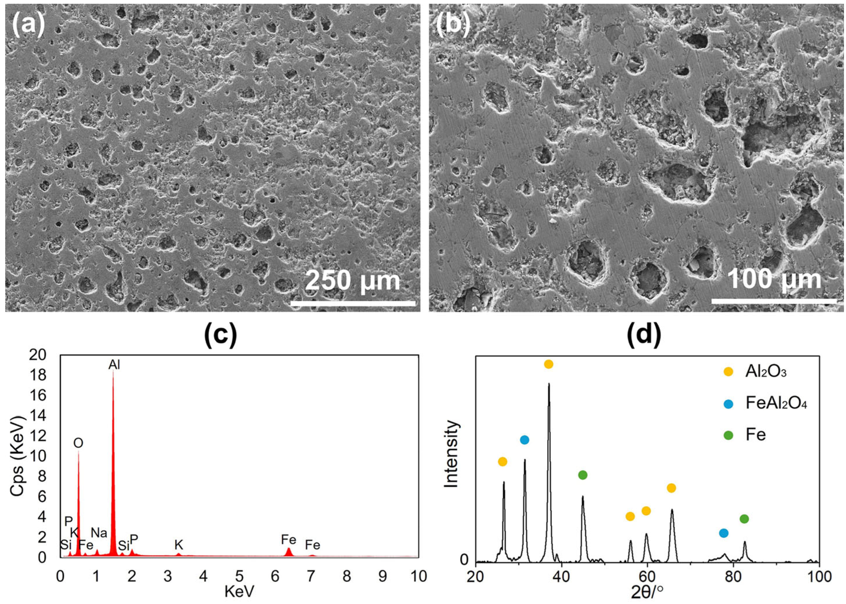
Figure 2a,b displays SEM images of the coated cast iron rotor surface at different magnifications, revealing a characteristic dimple-like morphology. This surface texture is a result of the plasma discharge events occurring during the coating process, which contribute to the formation of porosity (~10–12%). An EDX surface analysis of
Figure 2a was utilized to determine the elemental composition of the coating, confirming aluminum and oxygen as the primary elements, as shown in
Figure 2c. This indicates that the coating primarily consists of aluminum oxide, with a minimal presence of other elements. To further investigate the phase composition, an XRD analysis was conducted. The XRD patterns, as shown in
Figure 2d, confirmed that the coating is mainly composed of
, with the presence of
. Additionally, peaks corresponding to Fe were detected, which are from the cast iron substrate. These observations align with the previous studies [
8,
10,
11,
12,
13], which have reported similar phase compositions and morphology characteristics in the alumina coating prepared using the PAECD technique. Vickers hardness measurements were conducted in the previous studies [
11], where the hardness of the alumina coating (with pores) is ~795 HV, higher than that of the grey cast iron (~185–250 HV). After the experiment, the roughness of the rotor surface with and without coating was Ra ~2.2 μm and Ra ~0.9 μm, respectively.
3.2. Brake Pad
Two pairs of commercial low-metallic front brake pads were used for the vehicle road test.
Figure 3a shows a photo of the new brake pad before the test. Using SEM–EDX, the chemical elemental distribution of the brake pad materials was determined in EDX mappings. The SEM image with EDX mapping of four main chemical contents of the original brake pad surface are given in
Figure 3d. Graphite in the brake pad material functions as a lubricant to reduce unexpectedly high coefficients of friction (COF), which can otherwise cause brake system overheating. Steel fibers working as reinforcing fibers are visible in the pad material shown in the SEM image. Mineral substances (containing iron (Fe), calcium (Ca), aluminium (Al), silicon (Si), magnesium (Mg), manganese (Mn), zinc (Zn), and barium (Ba)) are also used in the pad friction materials.
After the road test, the used brake pads for both PAECD-coated and uncoated brake rotors were removed and subjected to a second phase of the SEM–EDX analysis.
Figure 3b,c shows photos of the brake pads working with coated and uncoated rotors, respectively. The surface of the utilized brake pad for the uncoated stock rotor (shown in
Figure 3c) has some grooves that follow the rotational direction, while the surface of the pad for the PAECD-coated rotor (shown in
Figure 3b) is rather smooth. Those grooves on the pad surface worked with the stock rotor were attributed to the abrasive braking events. The wear debris from the cast iron rotor can cause such surface grooves in the direction of rotation on the pad surface. After applying the PAECD coating to the rotor surface, the friction type was changed from abrasive wear between the pad and cast iron to adhesive friction between the pad and the coating [
10,
11,
12], where the wear particles from the pad materials formed a smooth and thin transferred layer on the coated rotor surface due to the coating’s dimple-like morphology [
10,
11,
12,
13].
The EDX mappings illustrating the four main chemical contents of the used brake pads for both coated and uncoated rotors are presented at the bottom of
Figure 3e,f. Comparing them to the EDX mapping of the original pad surface, the used pad surface for the PAECD-coated rotor exhibits an increased presence of Al. This elevation is attributed to the slight polishing wear of the alumina-based coating’s top layer. In contrast, the brake pad surface worked with the uncoated stock rotor shows a much higher concentration (indicated by the much brighter colour in EDX mapping) of Fe compared to other situations. This discrepancy arises from the cast iron rotor surface, where iron was worn off and subsequently picked up by the brake pad surfaces during the abrasive braking events [
14].
In the middle of the entire road test (~9000 km), the brake pads tested with the as-installed rotors were replaced with two pairs of the same new pads. The thickness of the four pairs of brake pads, corresponding to both PAECD-coated and uncoated cast iron brake rotors, was measured both before the installation and after the road test.
Figure 4 shows the average thickness loss of brake pads on both inboard and outboard sides for PAECD-coated and uncoated stock brake rotors during the first (~4500 km) and second (~4500 km) halves of the road test. In the first half of the test (shown by the grey bars), the thickness loss of the inboard pad for the PAECD-coated rotor was slightly lower than that for the uncoated stock rotor. At the same time, the thickness loss of brake pads installed on the outboard side for both coated and uncoated rotors was very similar. In the latter half of the test (shown by white bars), it became evident that the brake pads working with the uncoated rotor, both inboard and outboard, experienced greater material losses compared to those with the coated rotor. Considering the pad thickness loss and the density of the pad materials, the total weight loss of brake pads on the PAECD-coated side was 33.14 g throughout the entire road test, while it amounted to 38.94 g for the uncoated side. As a result, the coatings resulted in an approximately 15% reduction in brake pad weight loss in total compared to the uncoated side. The relatively excessive material loss of the brake pads could be attributed to the drilled and slotted surfaces of the brake rotors.
3.3. Brake Rotor
Before the road test, the sporty passenger car was installed with the new PAECD-coated and uncoated stock cast iron brake front rotors (
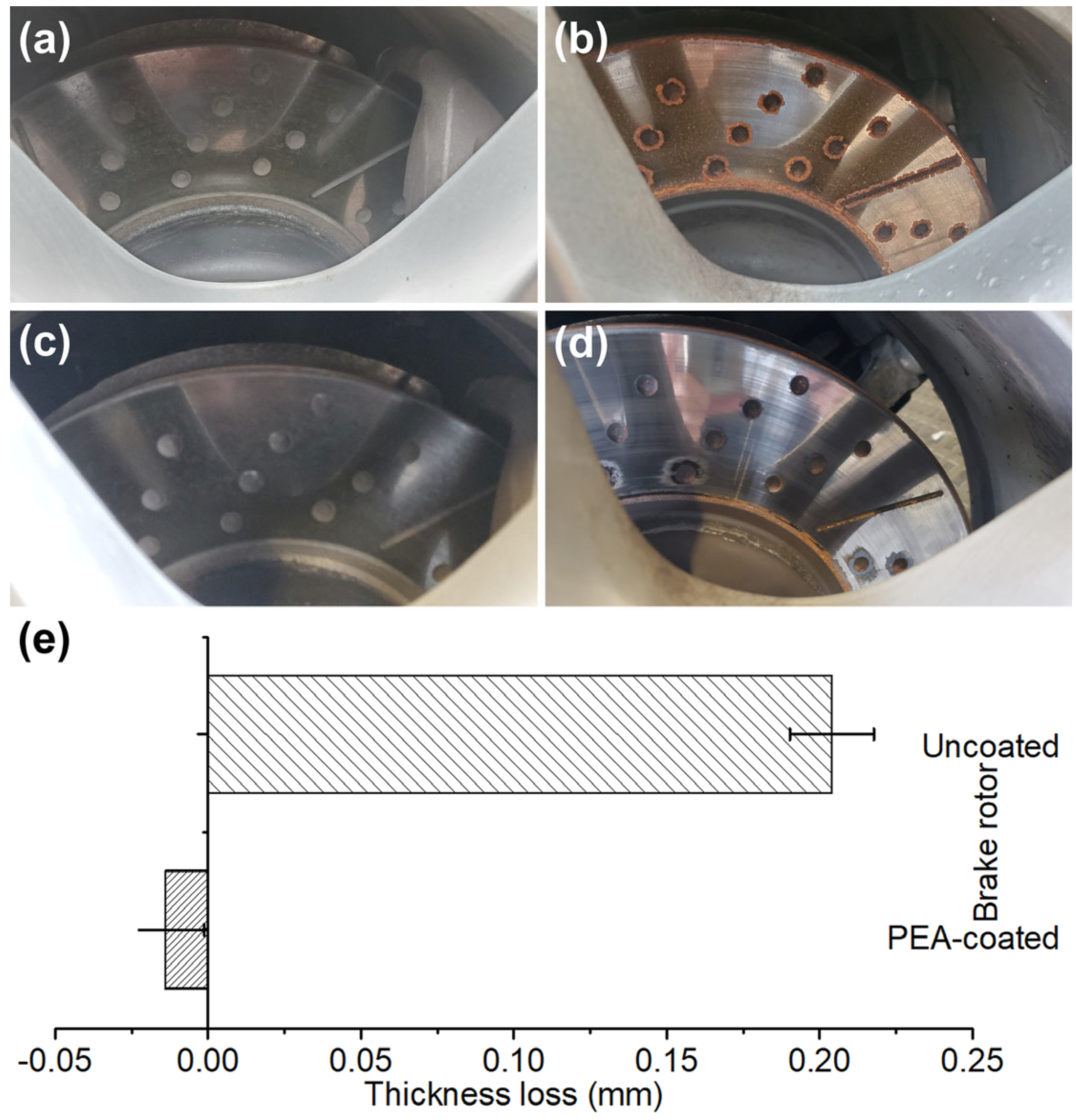
Figure 2). During the road test, the coated and uncoated brake rotors had photos taken of them from time to time. In a rainy day after one night of outdoor parking, pictures of the rotors with and without the PAECD coating are shown in
Figure 5a–d.
Figure 5b illustrates that some corroded rust appeared at the fringes of the friction ring and drilled and slotted areas on the uncoated cast iron surface during the wet weather, whereas none was seen on the PAECD-coated surface, as shown in
Figure 5a.
After parking outside, the road test with braking events proceeded again.
Figure 5c,d shows photos of the PAECD-coated and uncoated cast iron brake rotors taken following the braking events. The coated rotor surface (shown in
Figure 5c) looks the same as before, while the corroded rusty areas on the uncoated rotor (shown in
Figure 5d) were cleaned during the heavy braking, in which iron oxides, as the form of BWPs, were generated from the cast iron rotor surface. It has been stated that the corrosion issue on the cast iron brake rotor can increase both the number and mass of particle emissions by over 50% [
5]. The alumina-based ceramic coating can protect the cast iron brake rotors from their drawbacks of inferior corrosion resistance.
The PAECD coating on the cast iron rotor remains intact after the vehicle road test. Small worn steps are noticeable at the inner and outer edges of the friction ring surface of the uncoated rotor, whereas the coated rotor surface appears flat. Measurements of the coated and uncoated rotor thickness were taken before the installation and after the road test.
Figure 5e depicts the average thickness loss for both rotors. The uncoated stock rotor experiences a loss of over 0.2 mm in overall thickness, whereas the coated rotor’s total thickness slightly increased.
The weight loss of the uncoated brake rotor throughout the road test is about 69.97 g based on thickness loss, nearly double the total pad weight loss on the same side (38.94 g). The uncoated rotor contributed to about 64% of the total weight loss in the brake rotor and pad system. The increased average thickness of the coated rotor is attributed to the thin transferred layer formed on the coating surface due to friction materials from brake pads. The difference in thickness variation indicates that the passenger’s side with the stock rotor produced significantly more wear particles from the brake rotor itself than the other side. Considering the total weight loss of the brake pads used for the coated and uncoated side, the brake pairs with PAECD coatings experienced a 70% reduction in total weight loss compared to those without the PAECD coatings. The PAECD coating demonstrates significant potential to increase the lifespan of the brake rotors and nearly eliminate the BWPs produced from the rotor itself.
3.4. BWP Analysis
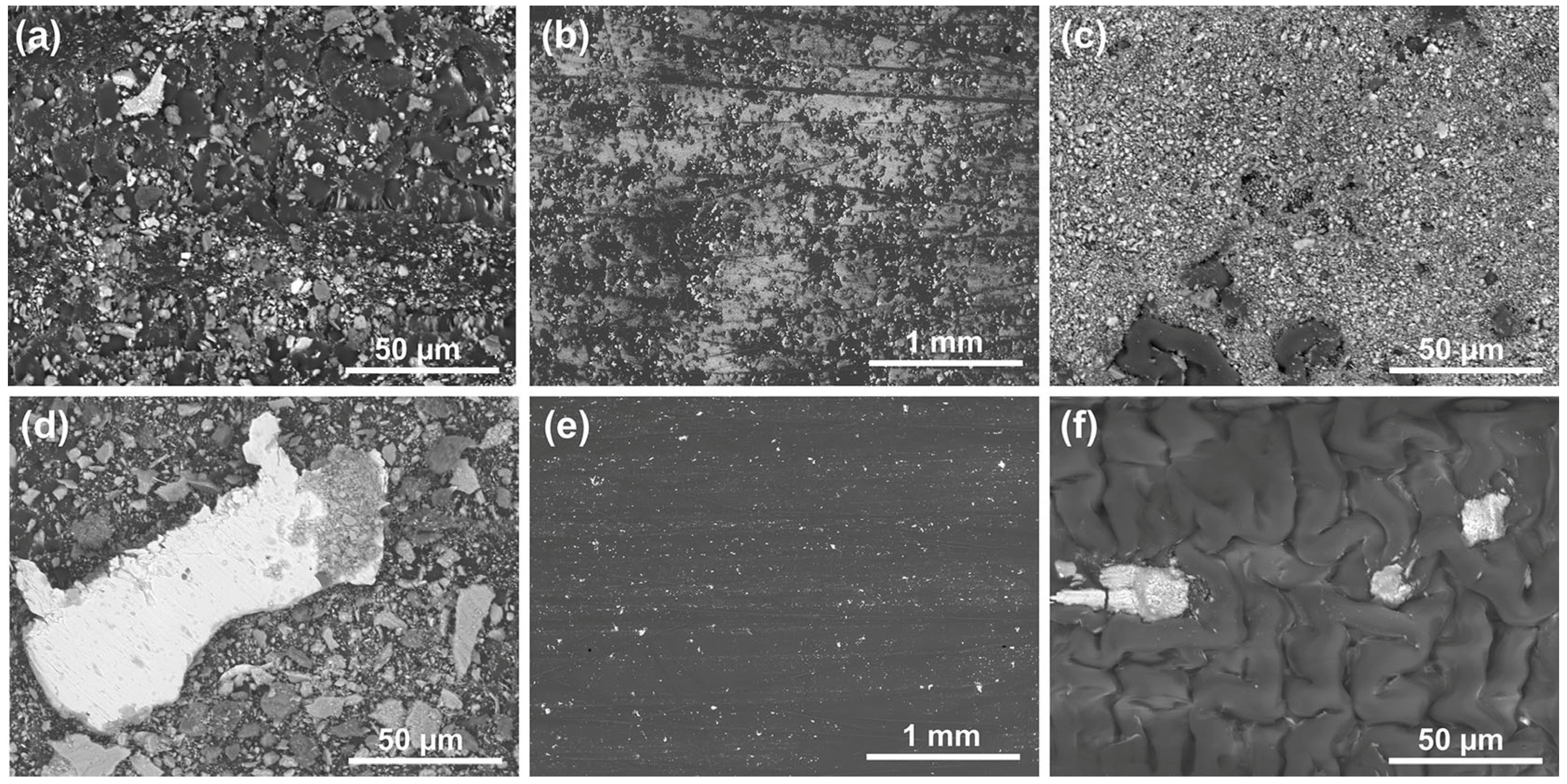
BWPs were collected from the surfaces of wheel barrels, spokes, and the friction rings of both rotors. The collected particles were investigated using SEM–EDX. SEM images in
Figure 6a,d depict BWPs collected from barrels of the brake systems with PAECD-coated and uncoated rotors under magnification of 1000. The particle size typically ranges from over 50 µm to less than 2.5 µm, categorized as fine particulate matter with a diameter of 2.5 µm or less (PM
2.5, particulate matter 2.5 µm or less in diameter). In
Figure 6d, the bright large particle, as identified through EDX analysis, consists of iron debris torn off from the uncoated cast iron rotor. The presence of the cast iron debris indicates severe wear on the cast iron rotor surface during friction braking events. Compared to
Figure 6a for the coated brake side,
Figure 6d shows a much larger number of BWPs collected from the uncoated brake side, indicating that the uncoated brake system generated more airborne BWPs, and that some of the particles were stuck on the barrels of the wheel.
When comparing the BWPs collected from the friction ring surfaces of the PAECD-coated and uncoated rotors, a noteworthy disparity emerges. The coated rotor surface, as shown in
Figure 6b,c, exhibits a significant number of BWPs. This elevated count is attributed to wear particles from the brake pad materials, which formed a thin transferred layer on the PAECD coating surface. Such a phenomenon was also previously found in small coupon-level lab tests [
10,
11,
12,
13]. This transferred layer not only provides additional protection for the substrate cast iron rotor, but also potentially retains wear particles produced during the braking events and prevents the immediate PM emission to brake corner component surfaces like spokes or the surrounding environment, owing to the dimple-like morphology of the PAECD coating surface. However, when a carbon tape was used to extract the BWPs from the coated rotor surface, the transfer layer was partially torn off and adhered to the carbon tape during the BWPs sampling collection, as shown by many particles in
Figure 6b. Even if the clustered BWPs (
Figure 6c), which appeared in the format of transfer layer [
10], were chipped off, the size of the BWPs would be much larger than PM
10 (particulate matter 10 µm or less in diameter), which is considered to be less harmful than small particles.
On the other hand, the number of BWPs collected from the uncoated rotor friction ring surface (shown in
Figure 6e,f) is relatively minimal. This is attributed to the scarcity of pad materials transferred onto the rotor surface. Considering the weight loss data from the preceding sections, the total weight loss from the uncoated side is about 3.28 times that of the PAECD-coated side. Consequently, the BWPs generated from the uncoated side may exceed three times that of the other side. This emphasizes the role of the PAECD coating in substantially mitigating the release of BWPs onto the surface of the wheels and into the surrounding environment.
Figure 7a,b presents the SEM images of BWPs collected from the spoke surfaces with PAECD-coated and uncoated cast iron brake rotors at a magnification of 5000. The particle diameter in both instances ranges from more than 10 µm, between 2.5 and 10 µm (PM
10), to less than 2.5 µm (PM
2.5). Multiple characteristic spots were selected and subjected to EDX analysis. The chemical composition weight percentages of the chosen spots in
Figure 7a,b are shown in
Figure 7c,d. Additionally, the total chemical contents of the entire collected BWPs shown in
Figure 7a,b were also analyzed using EDX, and are presented in the late bars of
Figure 7c,d.
As shown in
Figure 7b, there are two different types of BWPs from the uncoated side, which are as follows: large particles with flat surfaces (Spots A–C) and smaller irregular particles (Spots D–F).
Figure 7d shows that the flat particles possess higher Fe content (67.82 wt% in average) than the irregular ones (53.88 wt% in average), which indicates that Fe from the stock rotor was transferred to the contact plateaus and formed metal pick-up (MPU) on the pad surface during brake events before being released as BWPs [
14,
15]
However, the correlation between the BWP morphology and Fe content observed in BWPs collected from the spoke surface with an uncoated rotor does not apply to those collected from the spoke surface with a PAECD-coated rotor.
Figure 7a obviously shows flat particles (Spots A and B) and irregular particles (Spots C–F). The flat particles are relatively small in both size and number, while the irregular particles tend to form small agglomerates. The small particles are agglomerated at the sliding interfaces, and the size of agglomerated particle is influenced by the strength of friction films on the contact plateaus [
15], indicating that the larger irregular particle agglomerates on the PAECD-coated side can be attributed to the formed transferred layers on the PAECD coating. Compared to
Figure 7a,b, the particles generated from the PAECD-coated brake corner are significantly larger in size. Furthermore, due to the absence of wear from the cast iron rotor matrix, there is almost no MPU from the brake rotor by the brake pad surface.
Shown in
Figure 7a,c, Spot A contains 68.24 wt% carbon, suggesting that this flat particle could be graphite or an organic material that detached from the pad materials. An irregular particle (Spot D) possesses the highest Fe content (39.73 wt%), while another irregular one (Spot E) contains the lowest Fe (20.23 wt%), excluding Spot A. Therefore, with the application of the PAECD coating, flat BWPs may not necessarily have higher Fe content than irregular ones. The contents of Al and other chemical elements at Spots B–F range from 7–10 wt% to 15–21 wt%, respectively. The presence of the Al element may originate from both the friction materials and the polishing of the alumina coating’s top loosening surface during the bedding-in process. It is essential to highlight that the alumina coating could only release aluminium oxide during braking events, devoid of toxic heavy metallic elements.
Figure 7d shows chemical compositions of the representative BWPs generated from the brake pairs with the uncoated stock rotor, which exhibits 2–3 times the weight percentage of Fe compared to those collected from the PAECD-coated side. Increased metallic content heightens potential health risks upon exposure to released particles. In contrast, the Al contents (less than 0.8%) and the other elements in the BWPs collected from the uncoated side are substantially lower than those from the coated side. The notably higher Fe contents in the BWPs collected from the uncoated side align with the considerable wear observed on the stock cast iron rotor.
Based on the EDX results and the absence of thickness loss for the coated rotor shown in
Figure 5e, nearly all of the Fe content in the BWPs on the coated side can be derived from the steel fibers and other friction materials containing Fe in the brake pads. Consequently, the BWPs predominantly originated from the brake pads when they were sliding against the PAECD-coated brake rotor. In contrast, a significant portion of the BWPs from the uncoated side comprises iron oxides formed from the cast iron rotor surface.

