
An Ultra-Low Power Sticky Note Using E-Paper Display for the Internet of Things


Abstract
1. Introduction
- Our life is unpredictable. For instance, a professor may have an office hour at 10 a.m. but may not arrive at the office at that time due to a flat tire, traffic jam, or other emergency. Using the proposed IoT-connected sticky note system, the professor can send a message from the road to the door display unit such as “In a traffic jam, I will be in at 10:15 a.m.”. Thus, the students who physically come to meet the professor are informed of the updated time.
- Businesses such as restaurants, shops, medical offices, etc., hang neon signs on doors or windows to display “Open”, “Closed”, etc. After manufacturing, the designs of these signs cannot be changed. Using the proposed system, the user could display any message, such as “Opening at 8 a.m.”, “Closing at 6 p.m.”, “Closed for the weather”, etc., from any place in the world and customize the message using various styles depending on holidays and emergencies. Motivational quotes and special items for sale related to an occasion could be displayed easily using the smartphone. This will attract customers and may increase profit.
- In hotels, the tradition is to hang a tag on the door indicating if the room service can be performed. Using the proposed system, the customer could send customized messages to the door display with service instructions. Thus, room service could be done more efficiently without verbal instructions.
- There are commercially available Internet-connected digital noticeboards used for applications such as sports matches and advertising. However, these devices are not designed for low-power operations that can run on batteries for a long time or smart home environments. In contrast, the proposed sticky note display is a compact, ultra-low-power device that could be easily placed anywhere in a smart home and could run for more than six months on battery power—without requiring cumbersome wiring for the power supply.
2. Related Works
3. Materials and Methods
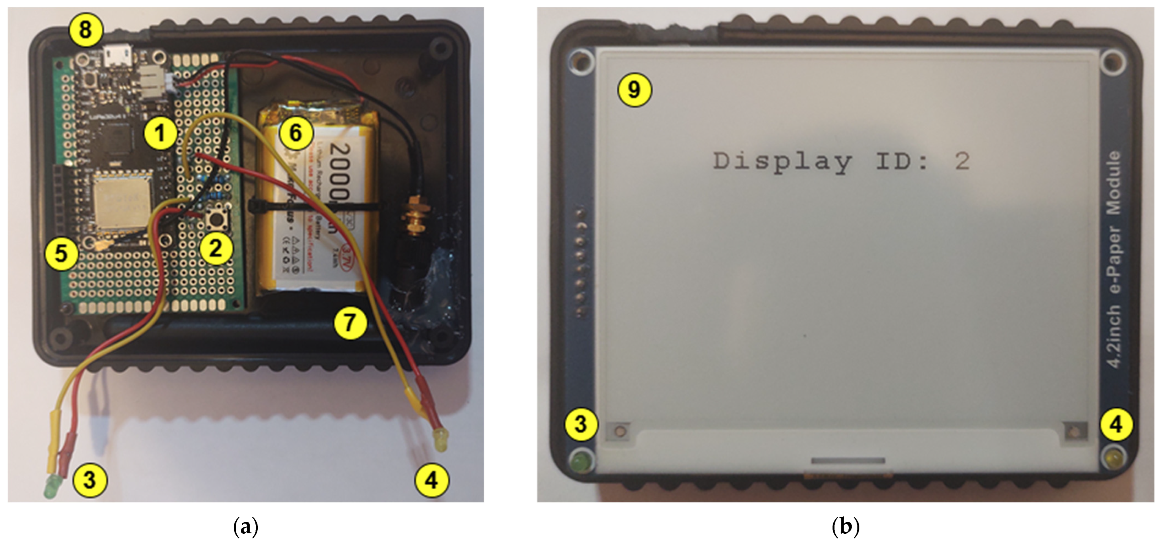
3.1. Ultra-Low Power Sticky Note Display Device
3.1.1. Hardware
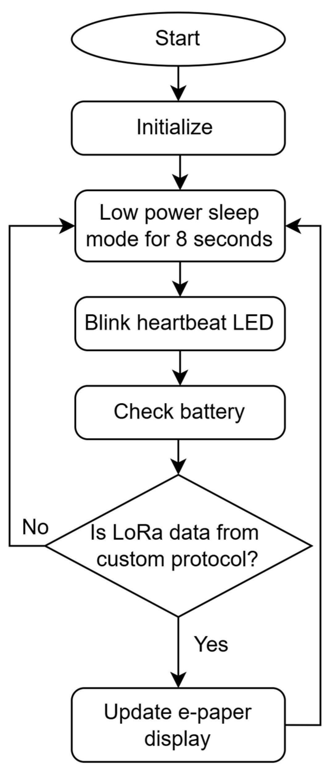
3.1.2. Firmware
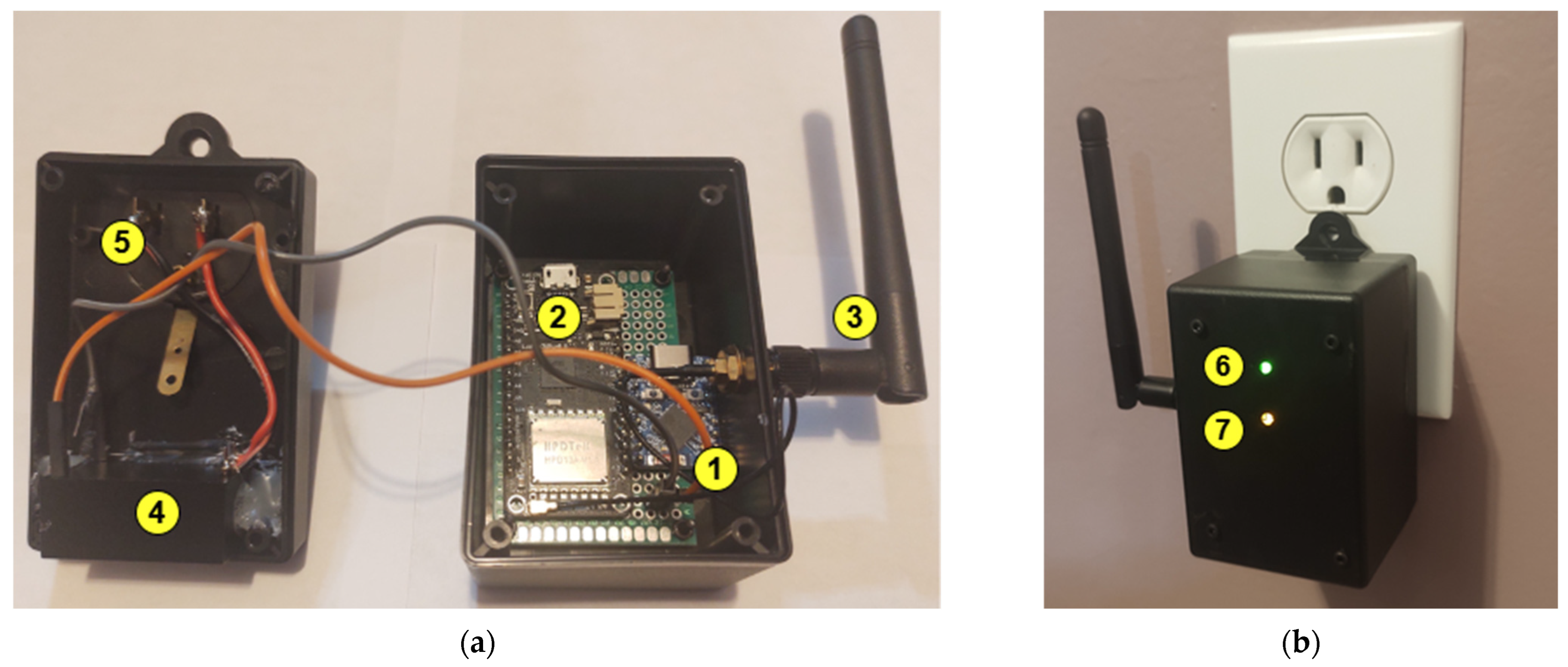
3.2. The Hub
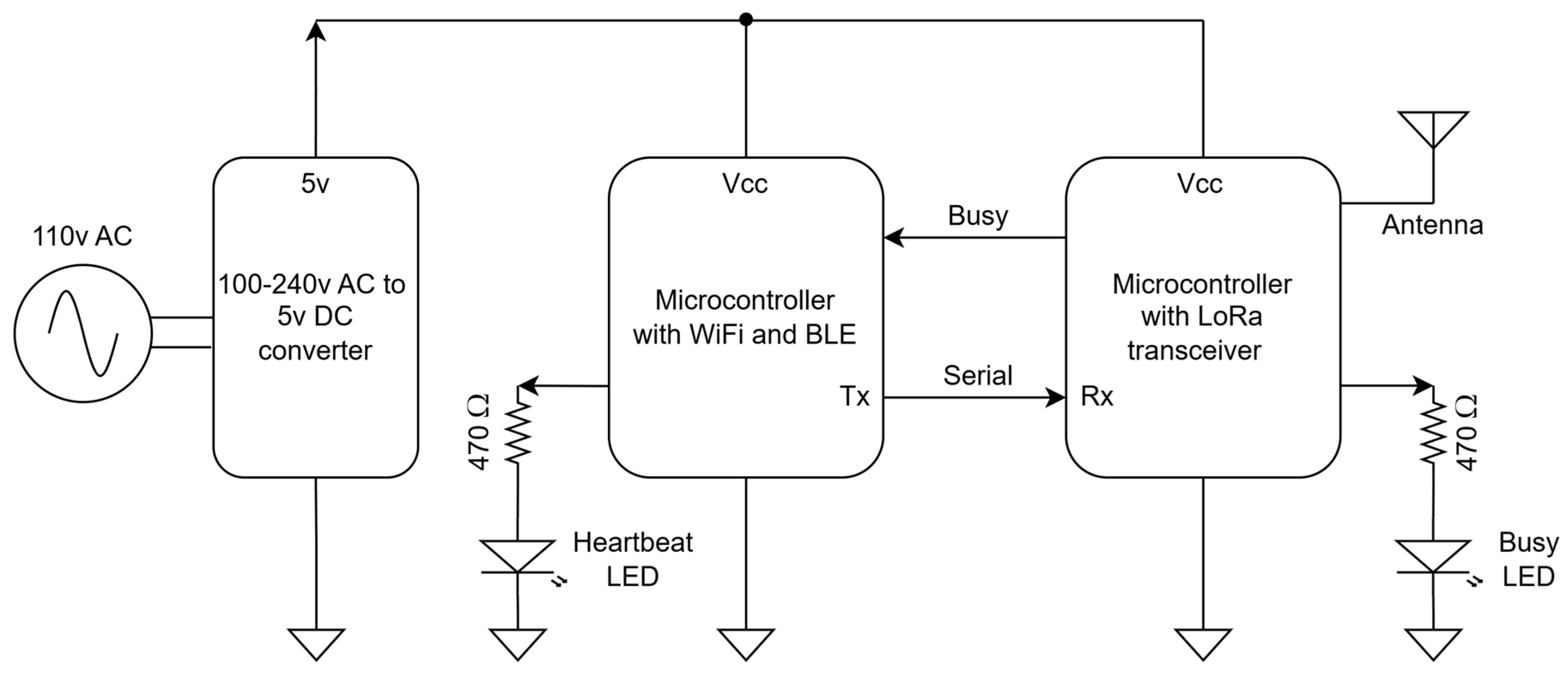
3.2.1. Hardware
3.2.2. Hub Firmware in ESP32-S3-Zero Microcontroller
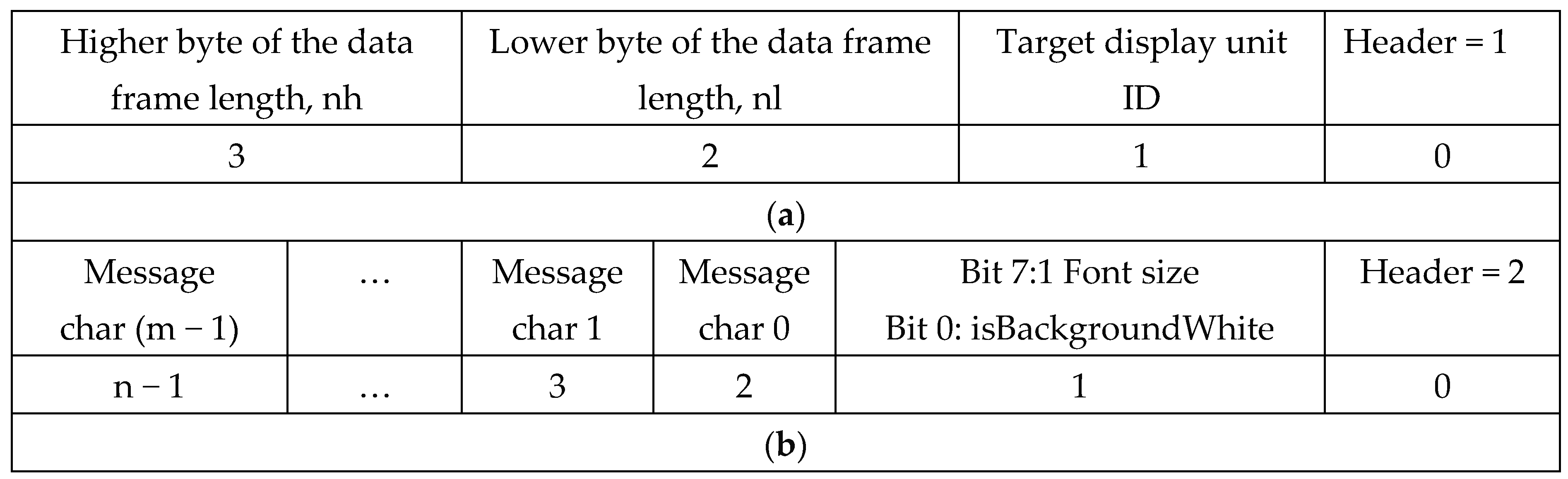
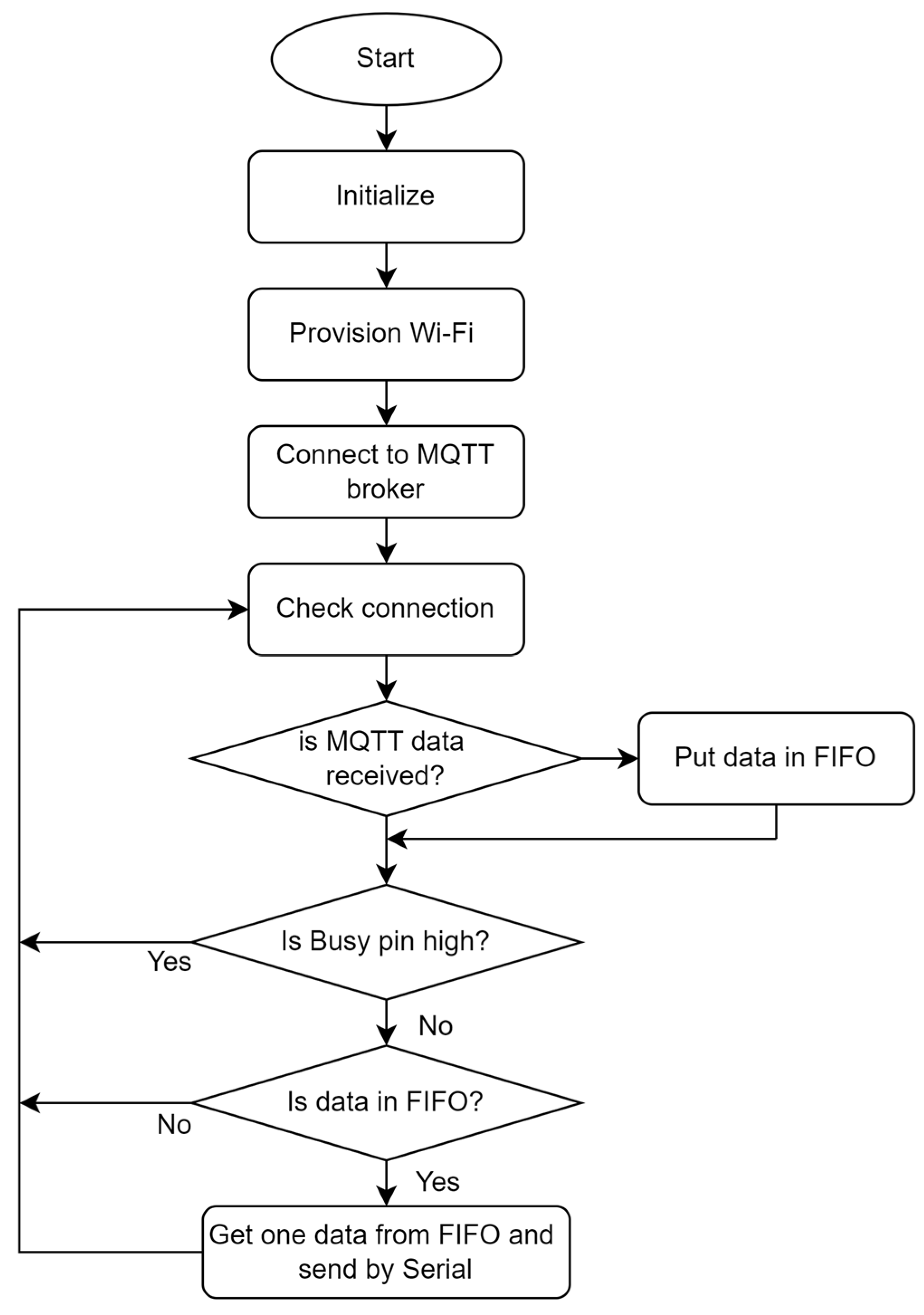
3.2.3. Hub Firmware in LoRa32u4 II Microcontroller
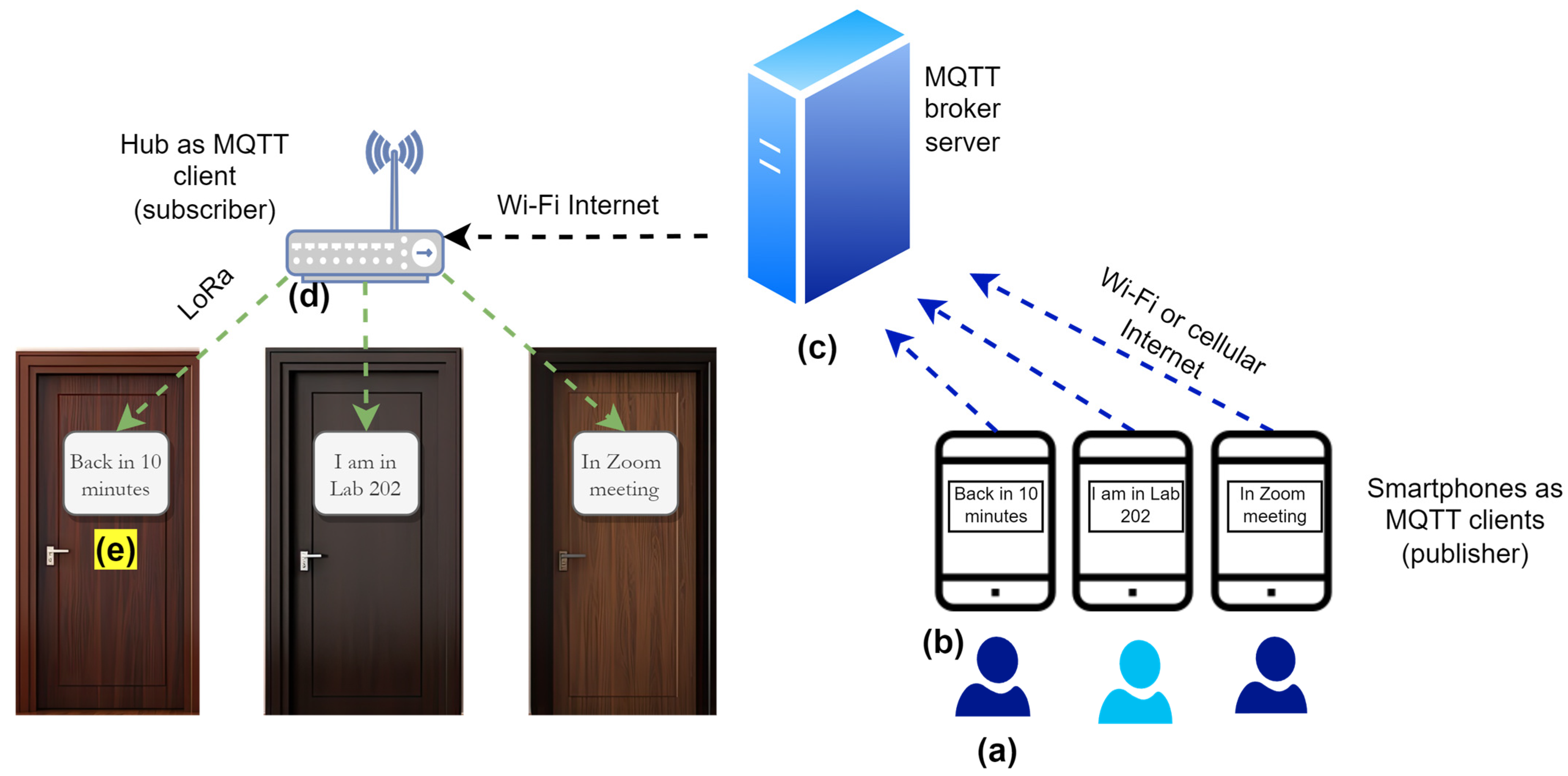
3.3. MQTT Broker Server
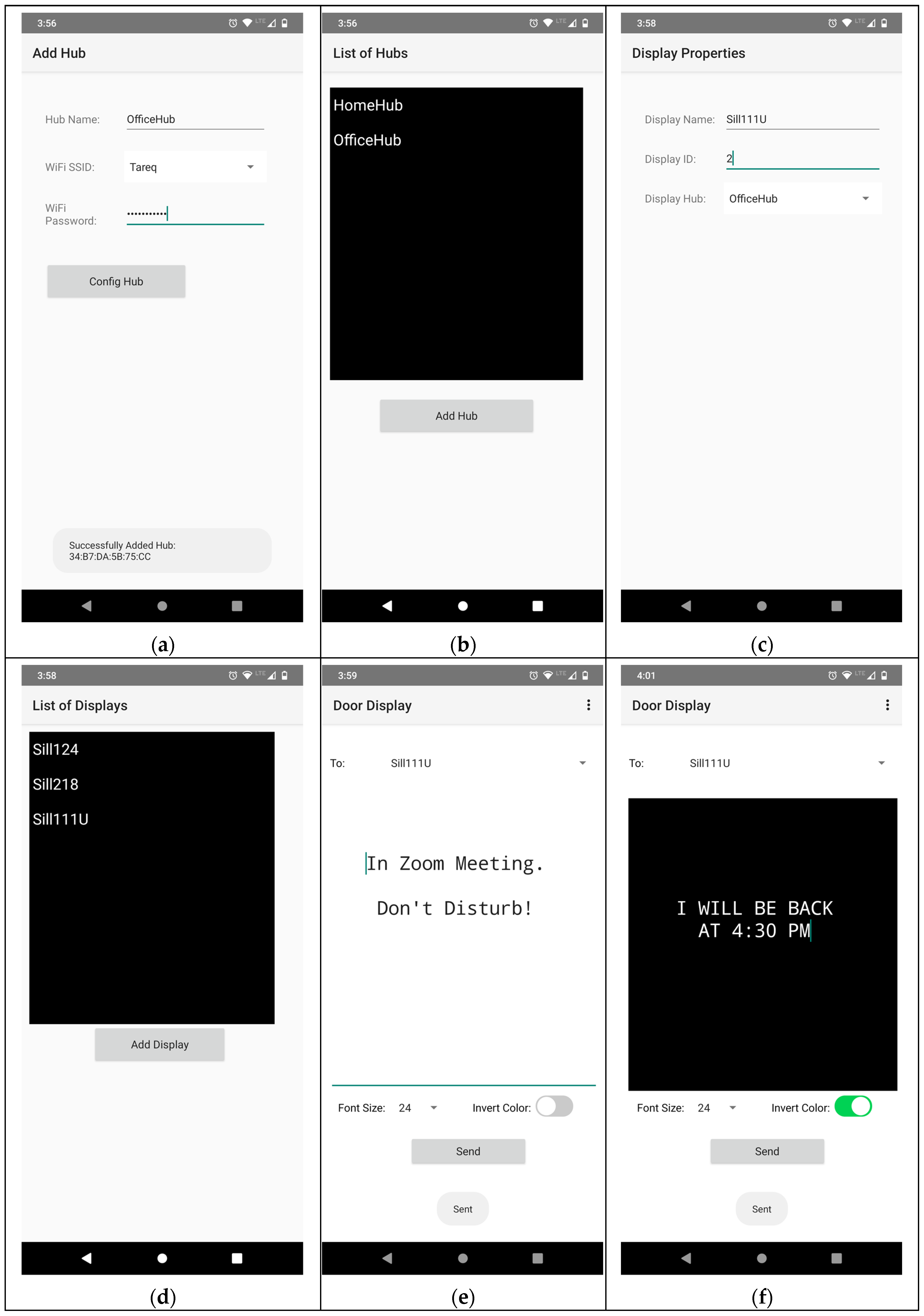
3.4. Smartphone App
3.4.1. Configuring Hub
3.4.2. Configuring the Sticky Note Display
3.4.3. Composing and Sending Messages
4. Results
4.1. Prototype Development and Testing
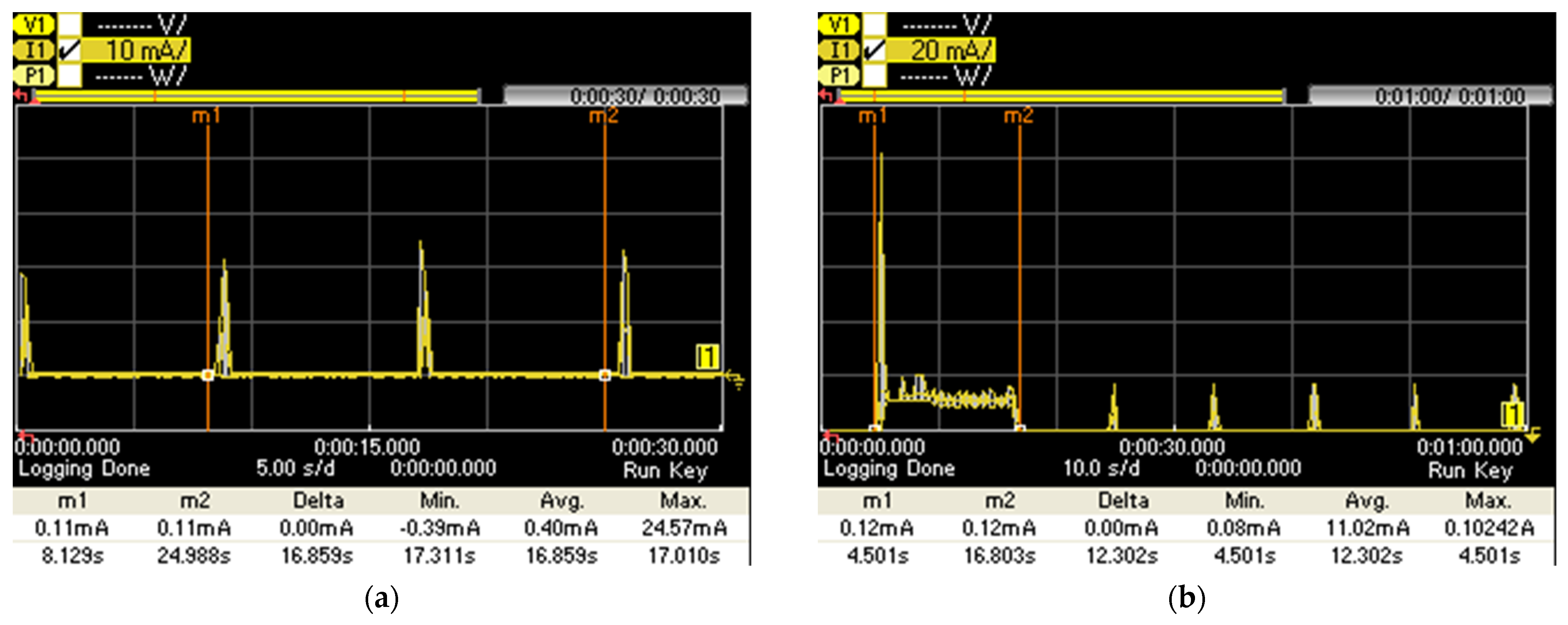
4.2. Current Consumption of the Sticky Note Display
4.3. Comparison with Other Works
5. Discussion
6. Conclusions
Funding
Data Availability Statement
Conflicts of Interest
References
- MQTT: The Standard for IoT Messaging. Available online: https://mqtt.org/ (accessed on 19 December 2024).
- Zourmand, A.; Hing, A.L.K.; Hung, C.W.; AbdulRehman, M. Internet of Things (IoT) using LoRa technology. In Proceedings of the IEEE International Conference on Automatic Control and Intelligent Systems (I2CACIS), Selangor, Malaysia, 29 June 2019; pp. 324–330. [Google Scholar]
- Kurian, N.S.; Kumar, R.H.; Shree, M.A.; Esakkiammal, S. IoT based Wireless Notice Board Using Raspberry Pi. In Journal of Physics: Conference Series, Volume 1979, Proceedings of the International Conference on Recent Trends in Computing (ICRTCE-2021), Maharashtra, India, 20–22 May 2021; IOP Publishing: Bristol, UK, 2021. [Google Scholar]
- Raspberry Pi Power Consumption. Available online: https://www.pidramble.com/wiki/benchmarks/power-consumption (accessed on 21 January 2025).
- ESP8266: Monitoring Power Consumption. Available online: https://thingpulse.com/esp8266-monitoring-power-consumption/ (accessed on 21 January 2025).
- P10 Single Red Color Led Module. Available online: https://ledworld.com/digital-signs/led-display-module/p10-single-red-color-led-module-320mmx160mm.html (accessed on 21 January 2025).
- Jha, G.K.; Singh, A.; Gupta, A.; Nigam, A.; Sharma, V. IoT and Bluetooth Enabled Wireless Notice Board. In Proceedings of the 2023 3rd International Conference on Advancement in Electronics & Communication Engineering (AECE), Ghaziabad, India, 23–24 November 2023; pp. 38–42. [Google Scholar] [CrossRef]
- ATmega2560 Datasheet. Available online: https://www.microchip.com/en-us/product/atmega2560 (accessed on 21 January 2025).
- Akintade, O.O.; Yesufu, T.K.; Kehinde, L.O. Development of Power Consumption Models for ESP8266-Enabled Low-Cost IoT Monitoring Nodes; Advances in Internet of Things; Scientific Research Publishing: Wuhan, China, 2019; Volume 9. [Google Scholar]
- HC-05 Bluetooth. Available online: https://athena-robots.readthedocs.io/en/latest/hc05_bluetooth.html (accessed on 21 January 2025).
- Gundavarapu, M.R.; Swapna, V.; Reddy, E.S.; Kumar, P.P.; Prathapani, A.; Shivaji, K. IoT-Enhanced Smart Bulletin Board: A Multi-Functional Connectivity Hub. In Proceedings of the 2024 2nd International Conference on Intelligent Data Communication Technologies and Internet of Things (IDCIoT), Bengaluru, India, 4–6 January 2024; pp. 1700–1704. [Google Scholar] [CrossRef]
- ESP32 WiFi and Low Power Modes. Available online: https://hackaday.io/project/193628-metashunt-high-dynamic-range-current-measurement/log/225599-example-esp32-wifi-and-low-power-modes (accessed on 21 January 2025).
- Surendiran, S.; Mathumathi, M.; Nivetha, S.; Lucina, A.P. IoT based Message Scrolling LED Display. Int. Res. J. Eng. Technol. (IRJET) 2020, 7, 223–229. [Google Scholar]
- SIM 900 GSM Modem. Available online: https://simcom.ee/documents/SIM900/SIM900_Hardware%20Design_V2.05.pdf (accessed on 21 January 2025).
- Arduino Uno Power Consumption: An In-Depth Analysis and Optimization Guide. Available online: https://embedwiz.com/arduino-uno-power-consumption/ (accessed on 21 January 2025).
- LoRa32u4 II Lora Development Board. Available online: https://www.amazon.com/Stemedu-LoRa32u4ii-Development-JST-PH2-0mm-2P-ATmega32u4/dp/B07MVTSGBB/ (accessed on 19 December 2024).
- ATmega32U4. Available online: https://www.microchip.com/en-us/product/ATmega32U4# (accessed on 21 November 2022).
- HPD13A 915MHz SX1276 Wireless Transceiver Module. Available online: https://dwmzone.com/en/lora-wireless-modules/613-hpd13a-sx1276-868mhz-915mhz-lora-transceiver-rf-module.html (accessed on 19 December 2024).
- Ferreira, A.E.; Ortiz, F.M.; Costa, L.H.M.K.; Foubert, B.; Amadou, I.; Mitton, N. A study of the LoRa signal propagation in forest, urban, and suburban environments. Ann. Telecommun. 2020, 75, 333–351. [Google Scholar] [CrossRef]
- 7V 2000mAh Lithium Rechargeable Battery. Available online: https://www.amazon.com/MakerFocus-Rechargable-Protection-Insulated-Development/dp/B08T6QS58J/?th=1 (accessed on 21 November 2022).
- MCP73831 Single Cell, Li-Ion/Li-Polymer Charge Management Controller. Available online: https://www.microchip.com/en-us/product/mcp73831 (accessed on 19 December 2024).
- 2inch E-Ink Display Module. Available online: https://www.waveshare.com/4.2inch-e-paper-Module.htm (accessed on 19 December 2024).
- ATmega32U4: I/O Ports (GPIO). Available online: https://medesign.seas.upenn.edu/index.php/Guides/MaEvArM-gpio (accessed on 24 February 2025).
- Low Power Library for Arduino. Available online: https://github.com/rocketscream/Low-Power (accessed on 23 December 2024).
- BSFrance LoRa Library for AVR Boards. Available online: https://github.com/BSFrance/BSFrance-avr (accessed on 23 December 2024).
- 2inch e-paper (B) V2 Routine. Available online: https://github.com/waveshareteam/e-paper/tree/master/Arduino/epd4in2_V2 (accessed on 23 December 2024).
- ESP32-S3-Zero. Available online: https://www.waveshare.com/wiki/ESP32-S3-Zero (accessed on 31 December 2024).
- HLK PM01 AC DC Converter 220V to 5V. Available online: https://www.amazon.com/EC-Buying-Step-Down-Intelligent-3-3V/dp/B09Z253MQ2/?th=1 (accessed on 31 December 2024).
- PM2320 AC Wall Plug Enclosure. Available online: https://www.polycase.com/pm2320#PM2320T03XWT (accessed on 31 December 2024).
- ESP32 BLE for Arduino. Available online: https://github.com/espressif/arduino-esp32/tree/master/libraries/BLE (accessed on 7 January 2025).
- ESP32 MQTT Library for Arduino. Available online: https://github.com/256dpi/arduino-mqtt (accessed on 7 January 2025).
- ESP32 Wi-Fi Library for Arduino. Available online: https://github.com/espressif/arduino-esp32/tree/master/libraries/WiFi (accessed on 7 January 2025).
- Eclipse Mosquitto: An Open Source MQTT Broker. Available online: https://mosquitto.org/ (accessed on 8 January 2025).
- Manage Password Files for Mosquito. Available online: https://mosquitto.org/man/mosquitto_passwd-1.html (accessed on 8 January 2025).
- How to Port Forward. Available online: https://www.noip.com/support/knowledgebase/general-port-forwarding-guide/ (accessed on 8 January 2025).
- How Do I Open a Port on Windows Firewall? Available online: https://www.howtogeek.com/394735/how-do-i-open-a-port-on-windows-firewall/ (accessed on 8 January 2025).
- No-IP. Available online: https://www.noip.com/ (accessed on 8 January 2025).
- Dynamic DNS Update Client (DUC) for Windows. Available online: https://www.noip.com/download?page=win (accessed on 8 January 2025).
- B4X MLwifi. Available online: https://www.b4x.com/android/help/mlwifi.html/ (accessed on 13 January 2025).
- B4X BLE 2—Bluetooth Low Energy. Available online: https://www.b4x.com/android/help/ble2.html (accessed on 13 January 2025).
- B4X jMQTT. Available online: https://www.b4x.com/android/help/jmqtt.html (accessed on 13 January 2025).
- N6705C DC Power Analyzer. Available online: https://www.keysight.com/us/en/product/N6705C/dc-power-analyzer-modular-600-w-4-slots.html (accessed on 13 January 2025).
- N6781A Two-Quadrant SMU for Battery Drain Analysis. Available online: https://www.keysight.com/us/en/product/N6781A/2-quadrant-smu-battery-drain-analysis-20v-1a-6v-3a-20w.html (accessed on 13 January 2025).
- Gavrilov, A.; Bergaliyev, M.; Tinyakov, S.; Krinkin, K.; Popov, P. Using IoT Protocols in Real-Time Systems: Protocol Analysis and Evaluation of Data Transmission Characteristics. J. Comput. Netw. Commun. 2022, 2022, 7368691. [Google Scholar] [CrossRef]
- Abdollahi, M.; Malekinasab, K.; Tu, W.; Bag-Mohammadi, M. Physical-Layer Jammer Detection in Multihop IoT Networks. IEEE Internet Things J. 2023, 10, 20574–20585. [Google Scholar] [CrossRef]
- ESP32-S3 Datasheet. Available online: https://www.espressif.com/sites/default/files/documentation/esp32-s3_datasheet_en.pdf (accessed on 24 February 2025).
- Wifi Power Save Example. Available online: https://github.com/espressif/esp-idf/tree/master/examples/wifi/power_save (accessed on 24 February 2025).
- Simpson, A.; Alshaali, M.; Tu, W.; Asghar, M.R. Quick UDP Internet Connections and Transmission Control Protocol in unsafe networks: A comparative analysis. IET Smart Cities 2024, 6, 351–360. [Google Scholar] [CrossRef]


| Performance | Without Low-Power Protocol | With Low-Power Protocol |
|---|---|---|
| Avg. current consumption (mA) | 15 | 0.4044 |
| Battery life (days) | 6 | 206 |
| Kurian et al. [3] | Jha et al. [7] | Gundavarapu et al. [11] | Surendiran et al. [13] | Proposed | |
|---|---|---|---|---|---|
| Processing MCUs | Raspberry Pi 2 and NodeMCU | Arduino Mega 2560 | ESP32 | ATmega328 | ESP32-S3-Zero and LoRa32u4 II |
| Wireless connectivity | Wi-Fi | Wi-Fi and Bluetooth | Wi-Fi | GSM | Wi-Fi and LoRa |
| Internet access | App cloud | Telegram app | Firebase cloud | - | MQTT |
| Display hardware | P10 LED display | MAX7219 LED dot matrix | LED dot matrix | LED dot matrix | e-paper |
| Display retains image after power off | No | No | No | No | Yes |
| Display resolution | 32 × 16 | 32 × 8 | 64 × 8 | 32 × 16 | 400 × 300 |
| Wi-Fi provisioning using smartphone | No | No | No | No | Yes, using BLE |
| Device management using smartphone | No | No | No | No | Yes |
| Low-power firmware design | No | No | No | No | Yes |
| Battery level check | No | No | No | No | Yes |
| Current consumption (mA) | 3310 | 480 | 520 | 470 | 0.4044 |
| Battery life (hours) 1 | 0.6 | 4 | 3.8 | 4.2 | 4945.6 |
Disclaimer/Publisher’s Note: The statements, opinions and data contained in all publications are solely those of the individual author(s) and contributor(s) and not of MDPI and/or the editor(s). MDPI and/or the editor(s) disclaim responsibility for any injury to people or property resulting from any ideas, methods, instructions or products referred to in the content. |
© 2025 by the author. Licensee MDPI, Basel, Switzerland. This article is an open access article distributed under the terms and conditions of the Creative Commons Attribution (CC BY) license (https://creativecommons.org/licenses/by/4.0/).
Share and Cite
Khan, T. An Ultra-Low Power Sticky Note Using E-Paper Display for the Internet of Things. IoT 2025, 6, 19. https://doi.org/10.3390/iot6010019
Khan T. An Ultra-Low Power Sticky Note Using E-Paper Display for the Internet of Things. IoT. 2025; 6(1):19. https://doi.org/10.3390/iot6010019
Chicago/Turabian StyleKhan, Tareq. 2025. "An Ultra-Low Power Sticky Note Using E-Paper Display for the Internet of Things" IoT 6, no. 1: 19. https://doi.org/10.3390/iot6010019
APA StyleKhan, T. (2025). An Ultra-Low Power Sticky Note Using E-Paper Display for the Internet of Things. IoT, 6(1), 19. https://doi.org/10.3390/iot6010019