Article

Geotechnical Characterization, Risk Analysis, and Design of Stabilization Measures for a Landslide Along the RN16 Coastal Highway in Morocco: A Case Study at KP 178+000


1
Geophysics and Natural Hazards Laboratory, Department of Geomorphology and Geomatics, Scientific Institute, Mohammed V University in Rabat, Avenue Ibn Battouta, Agdal, P.O. Box 703, Rabat 10106, Morocco
2
Laboratory of Geoengineering and Environment, Cartography and Tectonophysics Team (CaTec), Department of Geology, Faculty of Sciences, Moulay Ismail University, Zitoune Avenue, P.O. Box 11201, Meknes 50050, Morocco
3
Water Resources Management Engineering Department, College of Engineering, Al-Qasim Green University, Babylon 51013, Iraq
4
Imam Ja’afar Al-Sadiq University, Baghdad 10053, Iraq
5
Center for the Restoration of Iraqi Marshes and Wetlands, Ministry of Water Resources, Baghdad 10001, Iraq
6
School of Public Management, Governance and Public Policy, College of Business & Economics, University of Johannesburg, Johannesburg 2006, South Africa
7
Department of Civil Engineering, College of Engineering, King Khalid University, Abha 61421, Saudi Arabia
*
Author to whom correspondence should be addressed.
GeoHazards 2026, 7(2), 68; https://doi.org/10.3390/geohazards7020068

Submission received: 7 May 2026 / Revised: 1 June 2026 / Accepted: 5 June 2026 / Published: 8 June 2026

Abstract

The study analyzes a major deep-seated landslide affecting National Road 16 at KP 178+000 in the Rif region of northern Morocco, a corridor repeatedly impacted by geotechnical instability. Using historical information, detailed geological mapping, multiple field campaigns, and extensive subsurface investigations (core drilling, inclinometers), the authors characterize the site as a complex setting of metamorphosed, fractured, and altered peridotites overlain by Quaternary sediments dipping negatively toward the Mediterranean. The landslide is interpreted as deep-seated planar translational landslide and has been exacerbated by human activity, specifically the placement of excavated material on the downslope side during road upgrade works in late 2019. Inclinometer data show active movement extending to at least 20 m depth, confirming the deep-seated nature of the instability. Three remediation strategies were implemented: shifting the road alignment with terracing, combining road realignment with soil nailing and slope reprofiling, and installing large bored piles tied back with anchors, following recommendations from an external expert. The authors emphasize that robust geological investigations and properly regulated construction practices are essential to reduce landslide risk for infrastructure built in mountainous coastal regions.

1. Introduction

For many years, the Coastal Route has been plagued by geotechnical instability, thereby threatening its structural integrity and safety [1,2]. In many areas, the constant occurrence of landslides, erosion, and Sediment Displacement along the coastal route has significantly impacted transportation efficiency while increasing the vulnerability of surrounding ecosystems and communities [3,4]. It is important to understand how each of these factors contributes to the overall instability of the coastal route, including geological composition, hydrological dynamics, and human influence (anthropogenic), to allow for effective mitigation strategies to be developed [5,6]. With effective mitigation strategies in place, the resilience of coastal infrastructure can be improved for the sustainable use and protection of the coastal environment [7,8].
Geotechnical problems of slope stability are frequent occurrences when constructing linear infrastructures over mountainous regions [9,10]. The Rif Mountain range, located in Northern Morocco, has a complex geology and tectonic evolution, steep slopes, and receives high levels of rainfall seasonally [11,12]; therefore, construction and/or maintenance of highways within this part of the country is extremely challenging [13,14]. The RN16 (the Mediterranean Rocade) is an essential social and economic connection between coastal cities and serves as a major route for regional economic development [12,15,16]. However, there are many areas of this highway that have experienced ongoing geotechnical hazards, including landslides, rockfall, and ground settlement [17,18,19,20].
An ongoing issue at the road section located at KP 178+000 in the Chefchaouen province is a well-established problem that has been experiencing instability for years. During the last 10 years, numerous documented geotechnical failures/repeated landslides or blockfalls have occurred. In 2012, when a landslide and blockfall event occurred, the road was realigned to construct a temporary road, and a riprap mattress was placed as a protective measure; however, despite these interventions, longitudinal fissuring and platforming continued into 2013. When attempting to excavate and remediate the site in 2017, there were major geotechnical failures; subsequently, following additional geotechnical failures in 2019, there was considerable instability along a length of approximately 600 m of the RN16.
Given the persistent, recurrent nature of the instability and the lack of a permanent solution, it was necessary to conduct an all-encompassing investigation into the causes of this chronic instability rather than continuing to treat each issue as it arose with short-term or temporary remedies. This study contains the recognition and diagnosis assessment, in order to propose appropriate solutions for this risk. This assessment was designed to evaluate the following: (i) the causes of the continual instability actions, (ii) an understanding of the geology, geotechnology (engineering) hydrological (water) and hydrological (water related) reasons for the failure, (iii) the single reason for the failure and the reasons why that failure occurs at that location and (iv) technical evaluations of options for effective repairs. This investigation involved the collection of past, current, and subsurface data to create an extensive case study for assessing and addressing land (landslide-related) failures that affect significant infrastructure.

2. Materials and Methods

2.1. Study Area

2.1.1. Geographical and Climatological Context

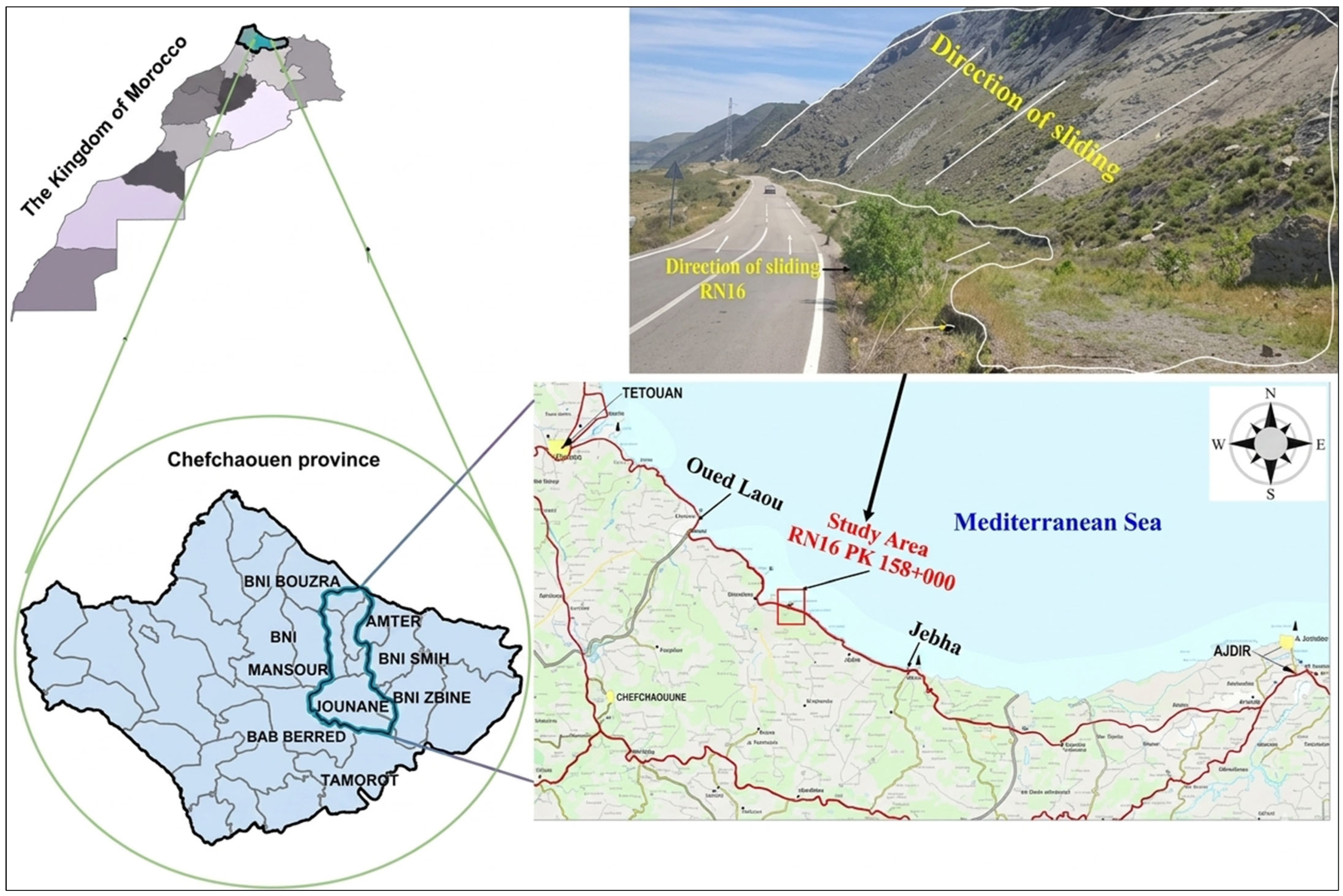
The study area is situated along the RN16, a major road connecting Tangier and Saidia. The specific section of interest is located 12 km southeast of Oued Laou and approximately 35 km northeast of Chefchaouen. The road descends through a series of switchbacks into the Targha valley. The study area is bound by coordinates X = 535,472.11/Y = 532,219.381 in the south, near Targha, and X = 536,670.859/Y = 530,164.851 in the Azenti area (Figure 1). Located in Northern Morocco in the Rif region, the study area has a typical mountainous landscape and a Mediterranean climate on its western coast. The climate can range between semi-arid and humid conditions and is influenced by Mediterranean, oceanic, and continental climates. It is estimated that the western section of the Rif Mountain chain experiences an average rainfall amount (precipitation) exceeding 1000 mm/year, but can also receive upwards of 1800 mm/year in elevations above 3000 m. Alternatively, eastern areas of the Rif chain, such as Jebha and Al Hoceima, regularly experience semi-arid environmental conditions and receive less than 600 mm of precipitation each year. A coastal climatic gradient exists in the Rif region and becomes drier from approximately 634 mm/year of precipitation at Oued Laou to less than 337 mm/year at Jebha (Figure 1).

2.1.2. Regional Geological and Tectonic Framework

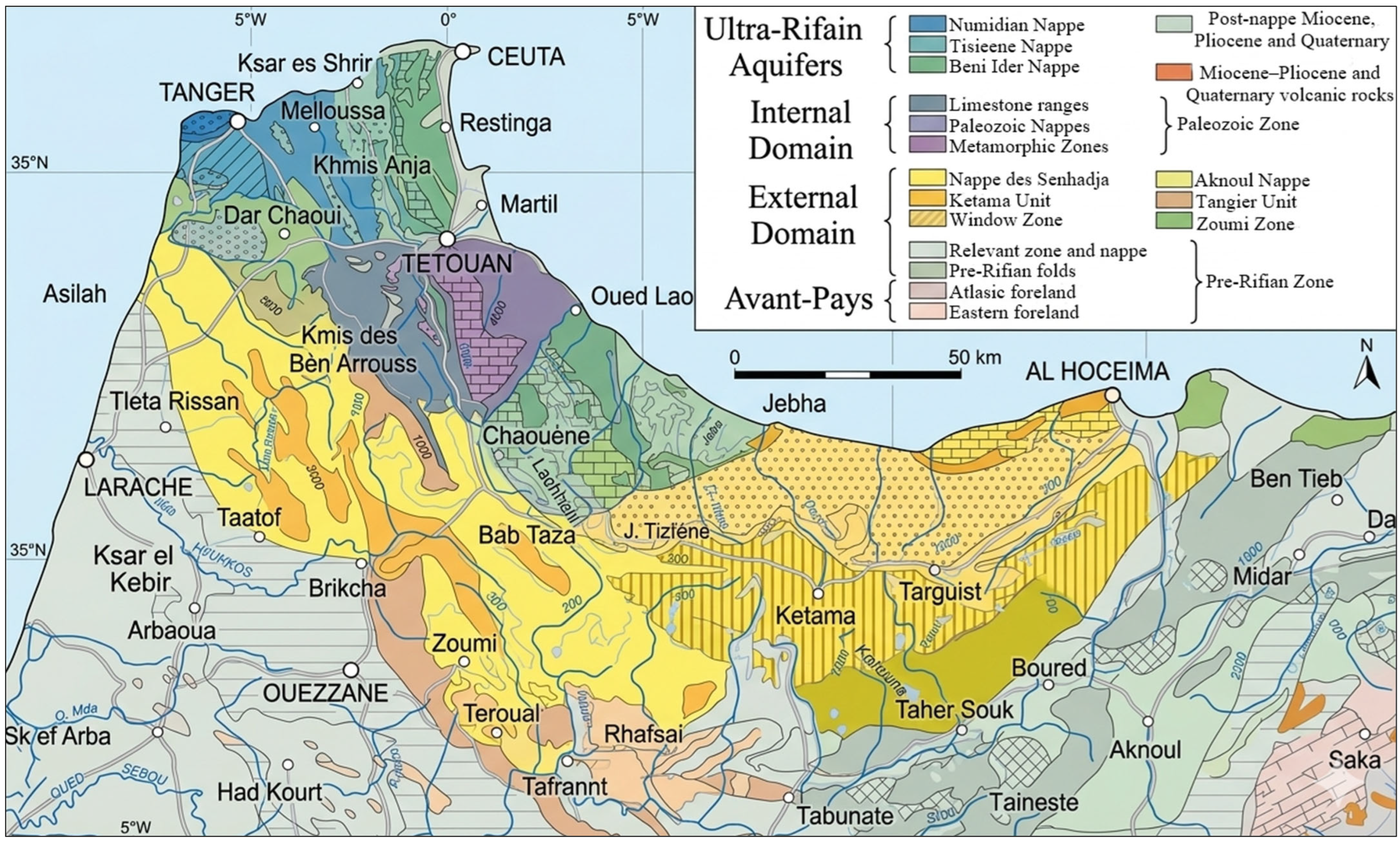
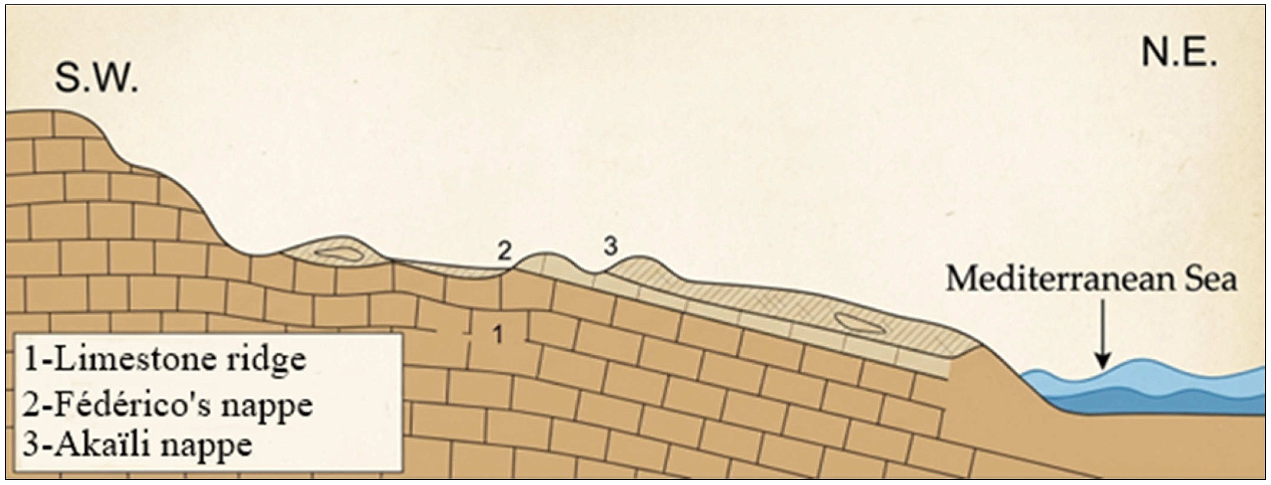
The Rif domain is the northernmost region of Morocco’s geological establishment, which is the only Mountain range in Morocco created during the Alpine Orogeny phase. Its structure is incredibly complicated due to large quantities (or Nappes de Charriage) originating from the north of the Rif Mountain Region and being pushed to the south across the continental plate of Morocco (autochthone) during Tertiary geological events (1). The location of the site (KP 178+000) studied in this research belongs to the Rif domain of the Alpine Range, specifically the Oued Laou–Jebha area, which is made from Paleozoic formations combined with metamorphosed zones (Figure 2).
The inner parts of this structure can be divided into the crystalline substratum (the Sebtides) that is found on top of the non-metamorphic Paleozoic nappes, known as Ghomarides. The Sebtides are exposed in areas such as the Béni-Bouchera Massif, where they consist of peridotite, gneiss, and micaschist. The Paleozoic nappes contain the Akaïli Nappe, the Koudiate-Tiziane Nappe, and the Beni-Hozmar Nappe, which are composed of different kinds of rock types. In addition to the various rock types in the Devonian to Permian Periods, each nappe has a different composition of rocks such as schist, sandstone, limestone, and conglomerates (Figure 2). All of these rocks are associated with the same tectonic regime.

2.1.3. Local Geology and Hydrogeology

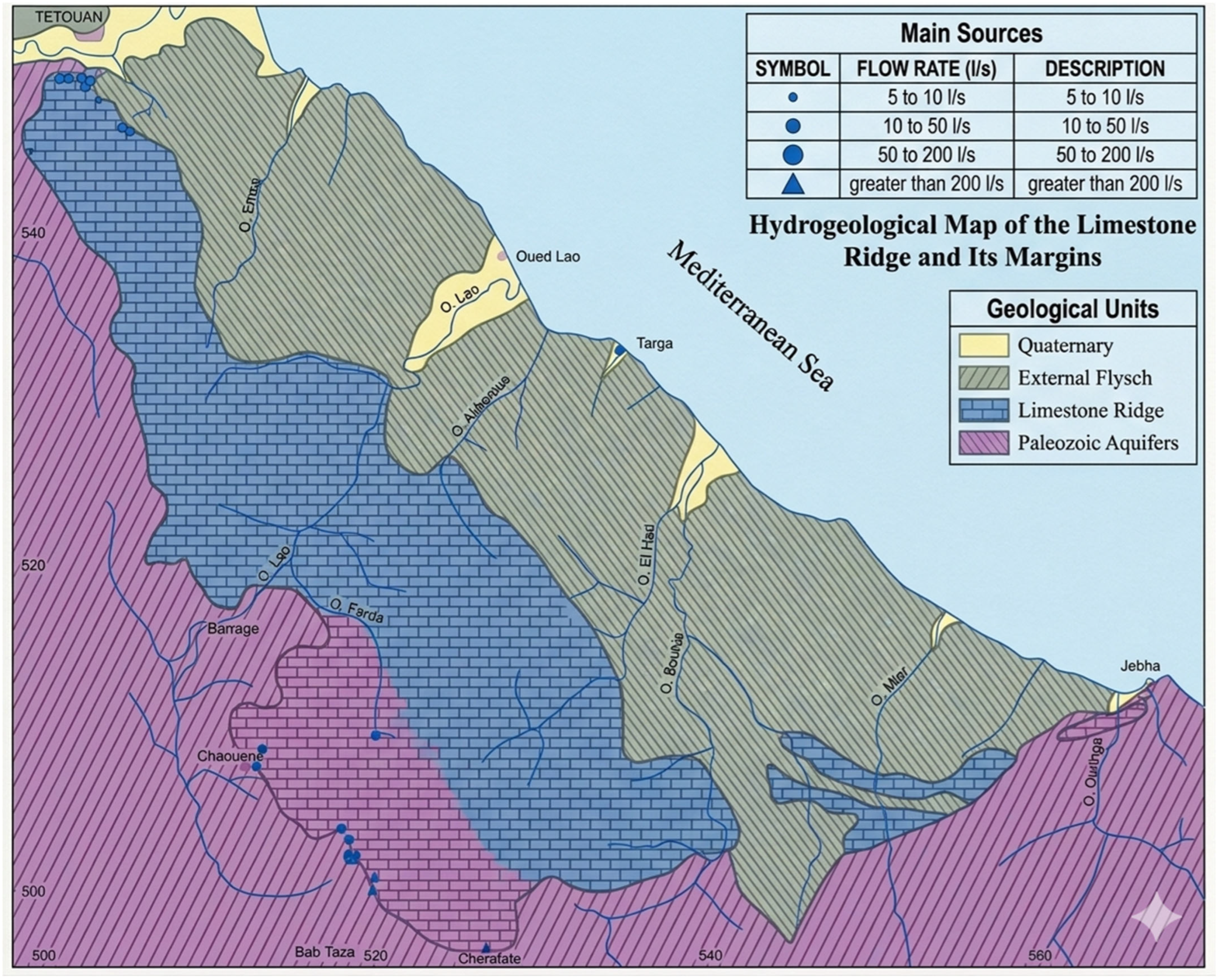
The study area is situated on highly fractured and altered peridotitic bedrock of the Sebtide unit (Beni Bousera). The intense weathering that has occurred in this area has led to the formation of numerous argillaceous veins within the rock formation, as demonstrated in borehole log data and field observations (Figure 3). Quaternary deposits, which include a mixture of cobbles, blocks, and naturally weathered peridotite debris, also cover some of the bedrock formations in this region.
A structural feature that has been confirmed through site visits and found on geological maps is that the rock mass has a large negative dip that is negative and has a significant impact on the stability of the rock mass due to the dip towards both the roadway and the ocean (Figure 4), creating an initial geological state that leads to a tendency for gravitational instability.
Paleozoic units are commonly viewed as impermeable to very poorly permeable, serving as a barrier to the flow of deep groundwater from hydrogeologic viewpoints. However, due to the moisture accumulation and weathering that have occurred at the surfaces of the formations, the weathered and fractured top portion can lead to poor, shallow aquifers. On the other hand, the anomalously high-water levels in the more permeable lenses (sandstones, conglomerates) may be present above the average water table as perched water levels and also generate small localized seepages and springs. Pore pressure from rain on slope stability and landslide hazards will be affected by the buildup of pore pressures from precipitation events. Pore pressure buildup usually results in increased pore pressures and decreased slope stability. Consequently, the accumulation of pore pressures causes an increase in landslide hazards during periods of extreme rainfall.

2.2. Data Compilation and Historical Review

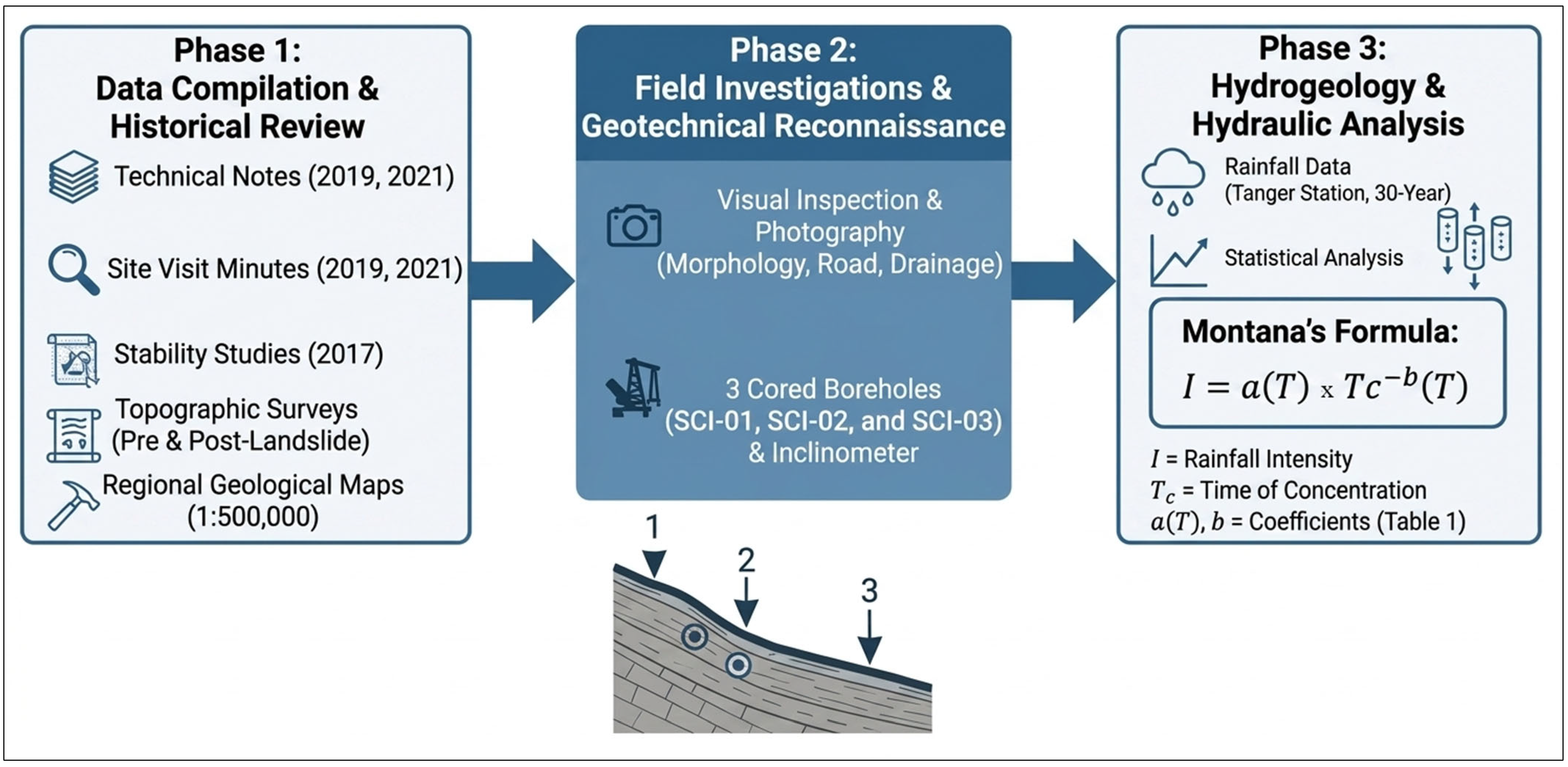
A thorough review of existing documentation was used for this study. Relevant documentation includes design consultant/independent expert technical notes, site visit reports (2019, 2021), stability studies (2017), topographic surveys (before and after the 2019 landslide), and regional geological maps (1:500,000). Historical information was critical for identifying how the instability developed/accessing previous intervention efforts.

2.3. Field Investigations and Geotechnical Reconnaissance

Multiple site visits were undertaken to assess the landslide’s morphology through visual inspection of the primary scarp, lateral edges, tension cracks, and low point. In addition to documenting the condition of the road, drainage structures, and the surrounding slope, many photographs.
The data obtained during the geotechnical investigation in 2019 under the guidance of the LPEE expert were used extensively in this research due to the fact that three 40 m-deep cored boreholes (referred to as SCI-01, SCI-02, and SCI-03) were drilled as part of the investigation. Two were drilled on the top of the road surface, while one was drilled on the higher side of the slope (Figure 5). Each borehole was equipped with an inclinometer casing to monitor subsurface deformation over time.

3. Results

3.1. Diagnosis of Instability and Failure Mechanism

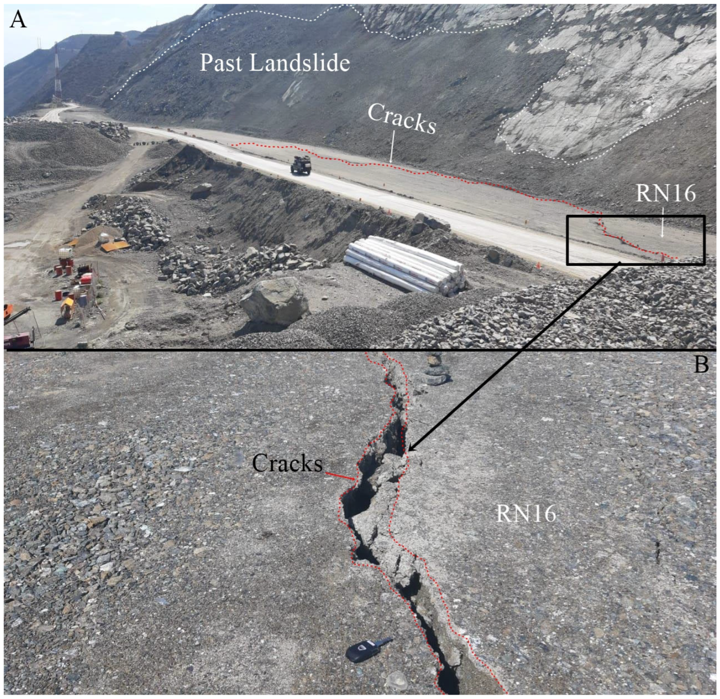
Field investigations confirmed the presence of severe and active instability. The primary manifestation was significant vertical settlement (Figure 6), with extensive longitudinal tension cracking associated therewith (many meters long, visibly open). Therefore, an active deep-seated planar translational landslide is indicated by these two features (longitudinal tension cracks and significant vertical settlement).
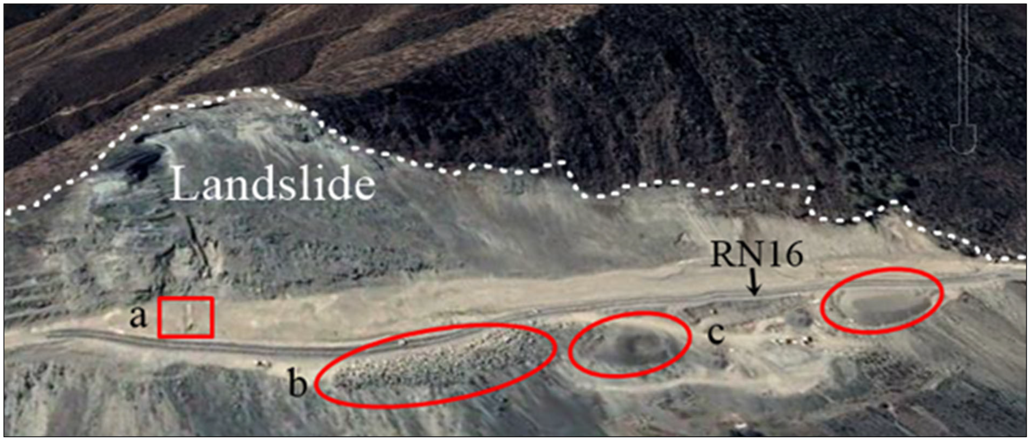
According to experts from the LPEE and the consultant’s expert team, the main cause of the failure in 2019 is the result of anthropogenic (i.e., human-created) triggers acting on a marginally stable slope. The main anthropogenic trigger is considered to be a surcharge load on the slope near the ocean (the area of importance for this collapse), resulting from large quantities of excavated fill deposited there. The excavated fill was generated by cutting the upslope side of the road during the widening work and was placed improperly in this area, which applied a substantial amount of load on the slope. This loading is clearly visible in photographs and satellite imagery (Figure 7).
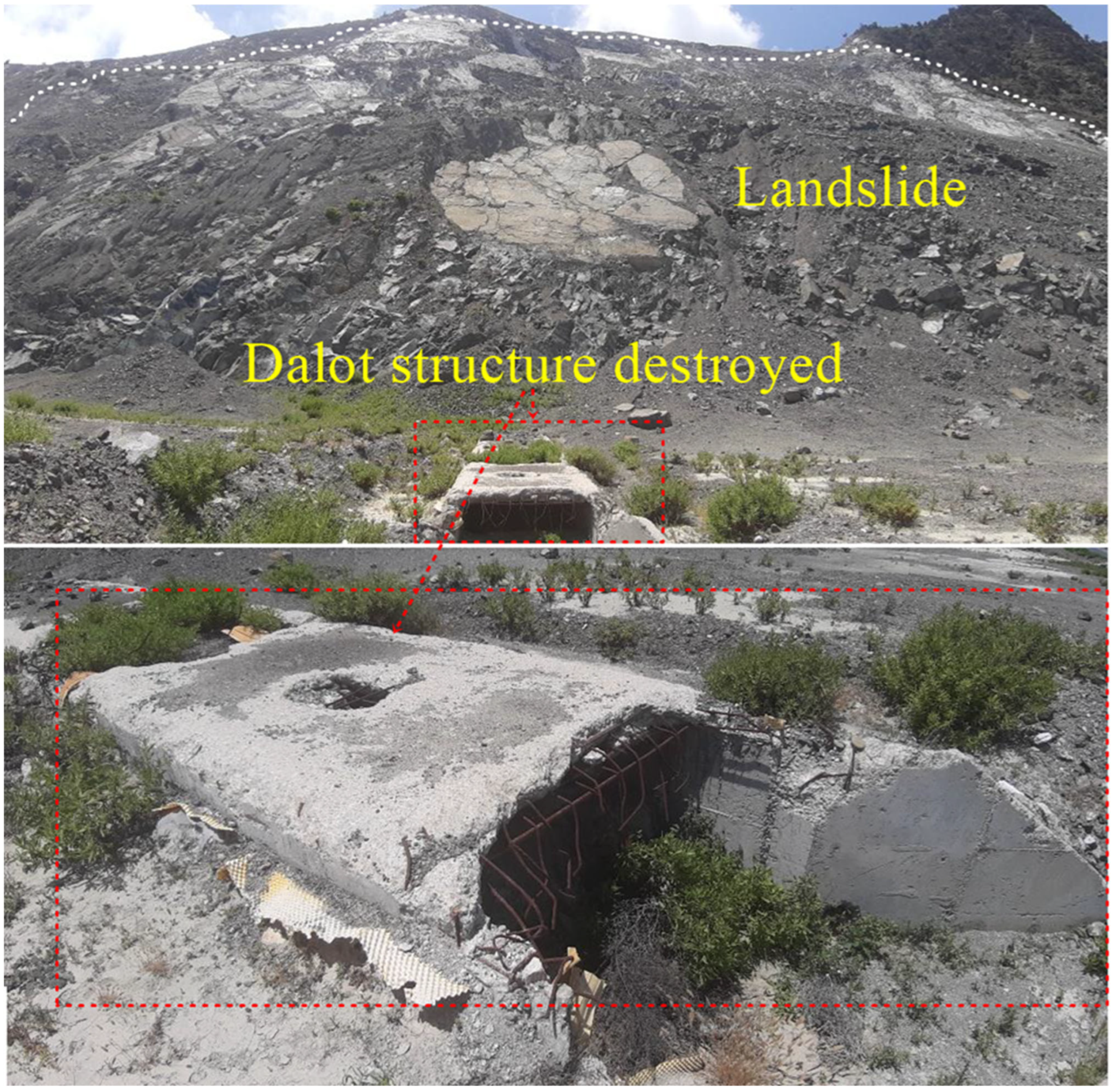
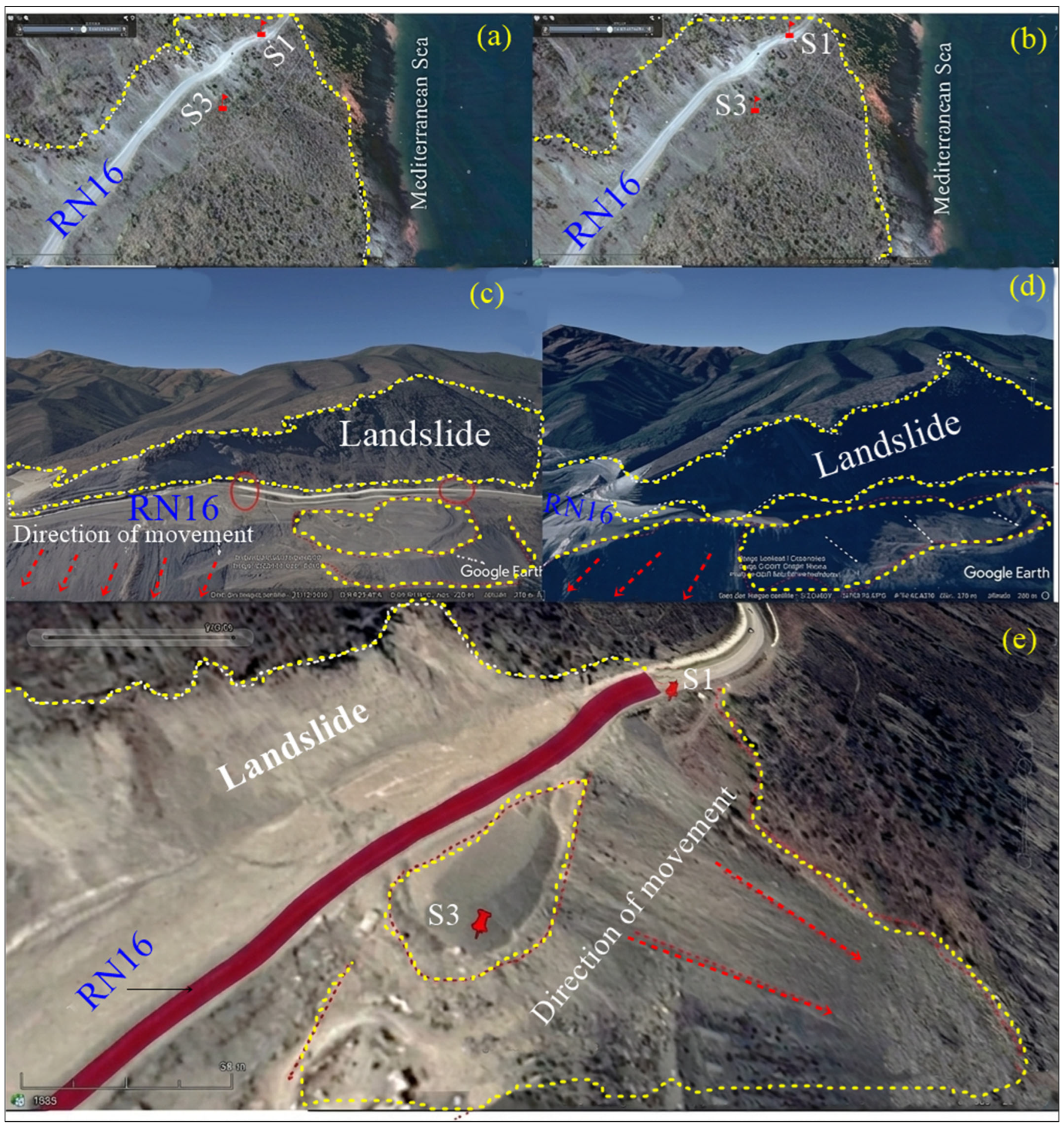
The temporal evolution of the landslide is illustrated in Figure 7. Based on the above, it can be inferred that a significant geotechnical hazard in the form of a major landslide occurred at the platform level, causing the mobilization of masses toward the toe of the seaward embankment (Figure 8). Indeed, these cascading landslides with subvertical rupture surfaces exhibit displacements on the order of a meter in places. Furthermore, it should be noted that the embankment-side landslide that occurred in 2017 affected part of the platform and some nearby sanitation structures. The figure below (Figure 9) shows the impact of the landslide on a 2 m and 1.5 m culvert-type structure that restores natural basin flows. It can be observed that this structure is blocked upstream. On the downstream side, it has been destroyed. In addition to this on-site analysis, a temporal evolution analysis of the study area was conducted between 30 August 2018 and 19 August 2019, using Google Earth images dated 30 August 2008, 7 August 2010, 15 December 2015, and 19 August 2019.
Indeed, the 2008 aerial images already showed that the initial road was built on the embankment foundation, and the materials on the seaward side had not yet been dumped. The image in Figure 9a shows the zone in 2008, before the RN16 road leveling works. The 2010 aerial image below (Figure 9b) shows the study area after deposition of materials from earthwork operations during the RN16 leveling. In 2015, according to the aerial image presented below (Figure 9c), it is evident that the platform was refurbished due to settlements that occurred at that level. In 2017, an embankment-side landslide was observed. This landslide affected part of the platform and adjacent sanitation structures (Figure 9d). The section marked in red on the 2019 aerial image, presented below (Figure 9e), corresponds to the deviated section of the RN16 road. This temporary deviation was constructed on a false embankment.
The deposits (materials from the embankment) as well as the deviated road exert additional forces on the false embankment due to their substantial weight, subsequently triggering instability manifested on the road by a longitudinal open fracture extending several meters in length.
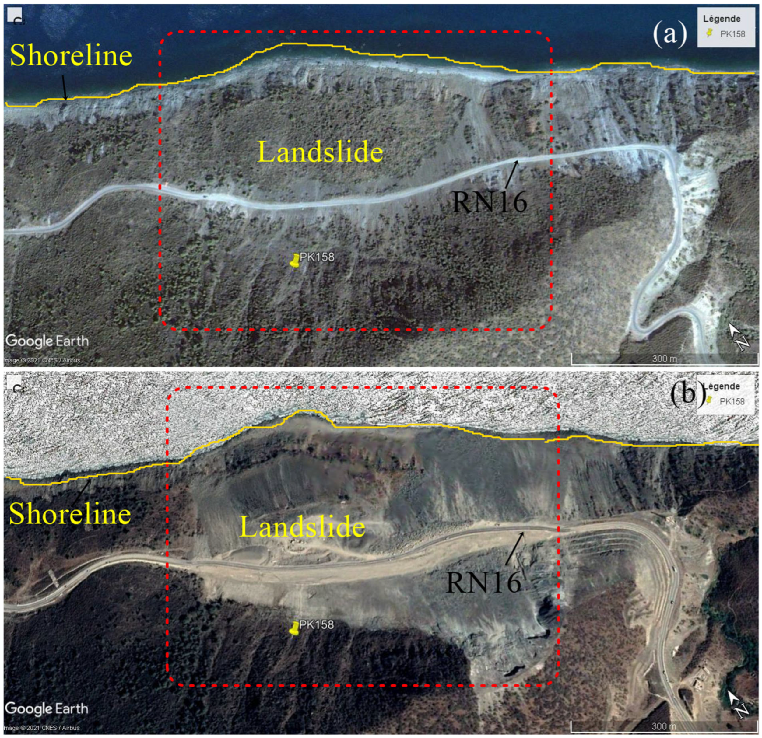
The shoreline exhibits a very pronounced bulge between the initial state (2008) and the current state, highlighting the significance of the slide mass and the depth of the slip circles, which likely extend below sea level. The bulge in question is clearly visible on the following Google image (Figure 10).

3.2. Geotechnical Investigation Findings

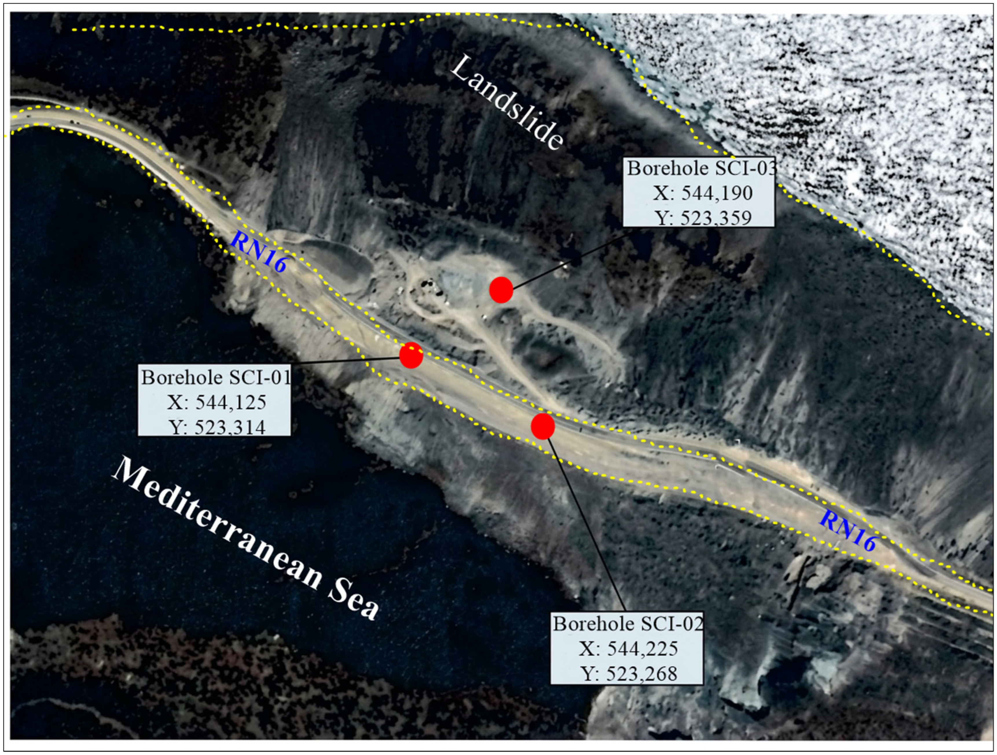
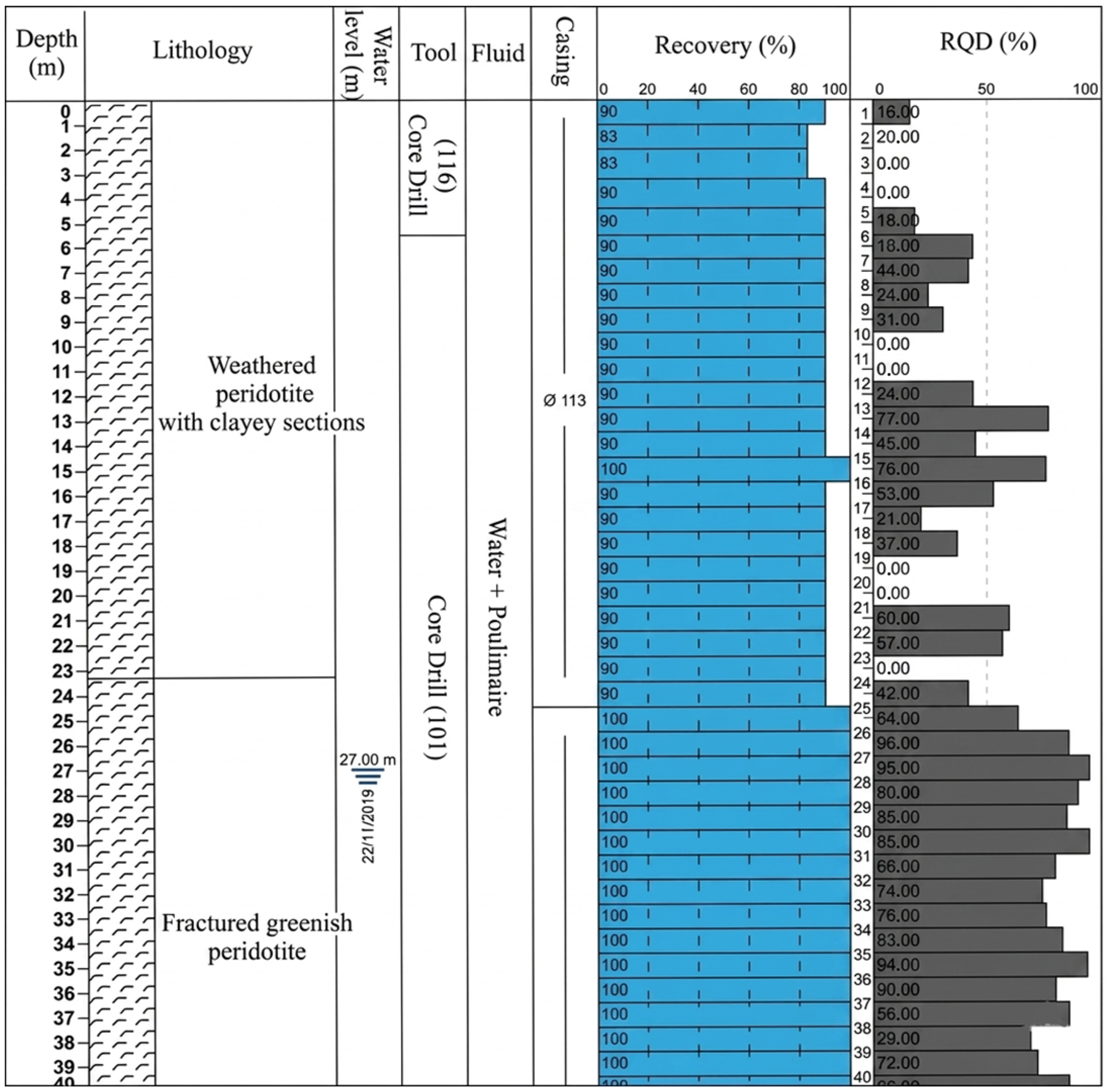
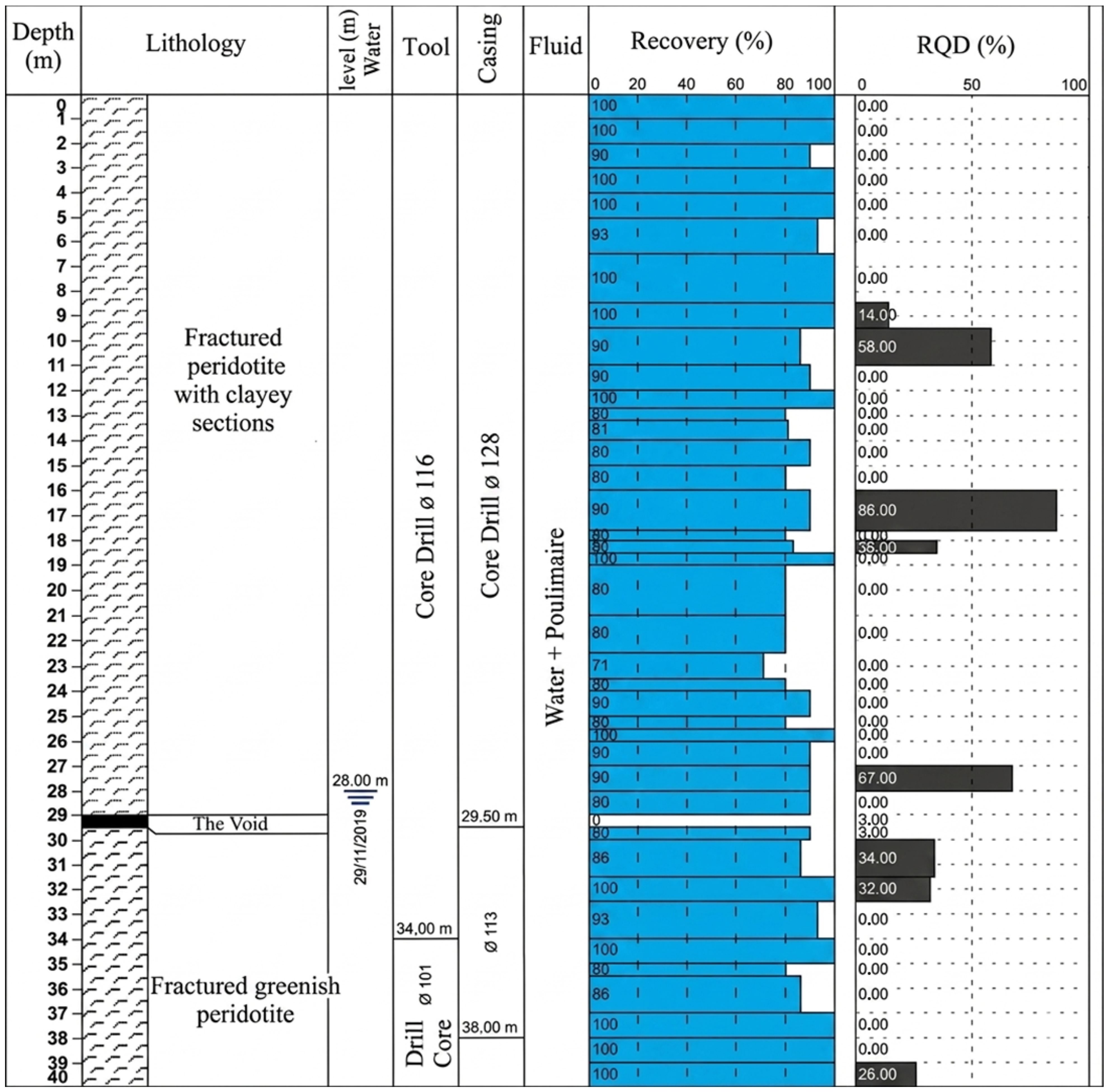
The three boreholes are 40 m deep and are located within the study area (Figure 11). Subsurface geological information acquired through cores taken at three boreholes supported the local rock type, with many fractures and/or alteration & with argillaceous voids, to a depth of 17 to 23 m (boreholes near road SCI-01 and 02) or 30 m in the downgradient borehole SCI-03 (Figure 11). At each of the three boreholes, fractured greenish peridotites are encountered.
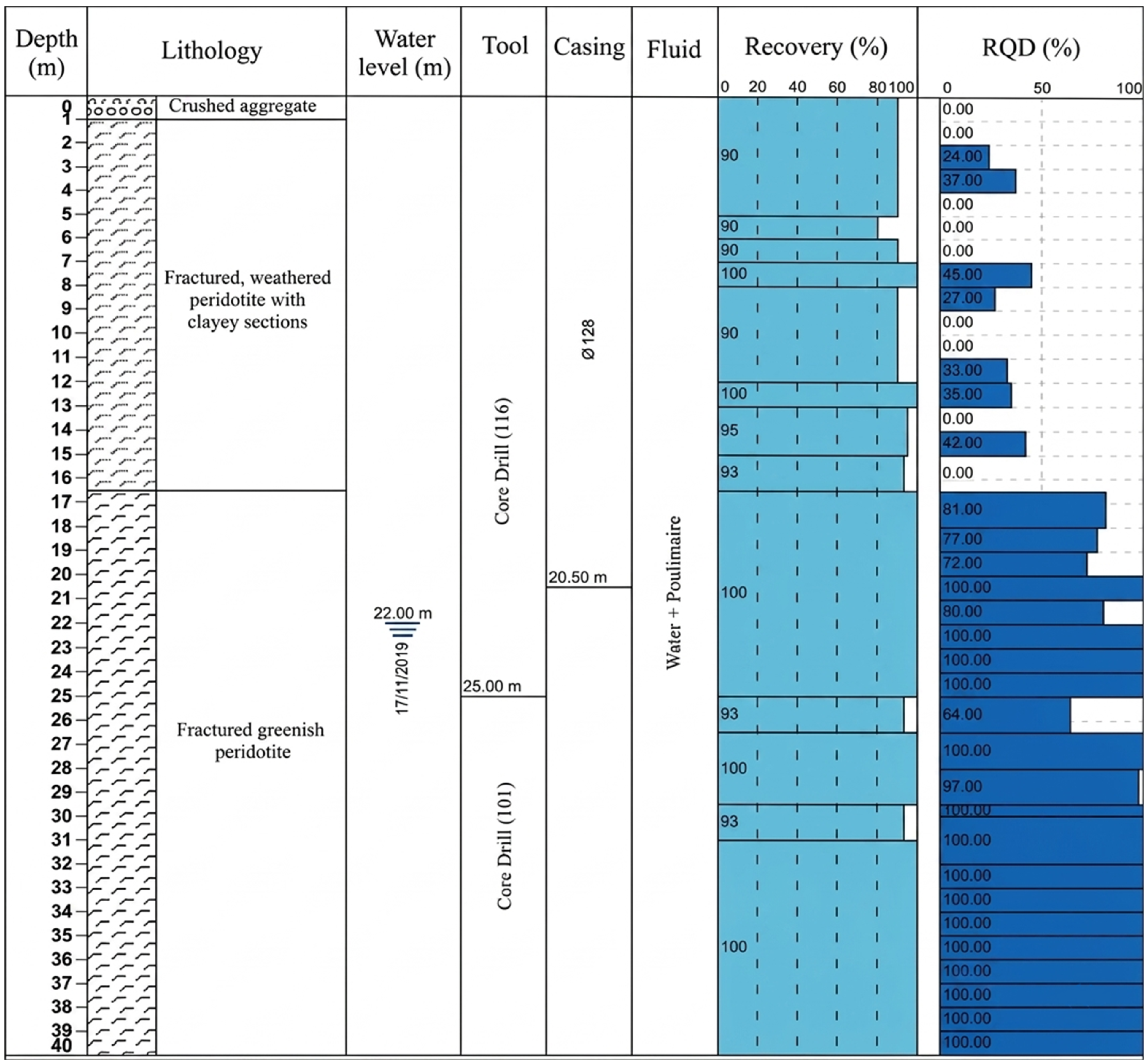
Borehole SCI-01, drilled to 40 m depth using rotary core drilling, revealed a lithological sequence entirely composed of peridotite structured into two geomechanically contrasting units separated by a sharp boundary at 16–17 m depth (Figure 12). The upper unit (0–16 m) consists of fractured, weathered peridotite with interbedded clayey sections generated by the supergenic alteration of olivine and pyroxene into phyllosilicate assemblages (serpentine, smectite, chlorite), characterized by very low residual friction angles (8–15°). Rock Quality Designation values within this unit are uniformly poor, with a mean of 18–22% and repeated null values indicating intensely fractured and clay-injected shear zones, corresponding to an estimated RMR of 15–25 (Class V). In contrast, the lower unit (17–40 m) of fractured greenish peridotite exhibits mean RQD values of 90–95% and an estimated RMR of 55–70 (Class II–III), reflecting a competent and mechanically intact rock mass. The static water table, recorded at 22.00 m depth, lies below the unit boundary, generating transient perched water conditions within Unit I during rainfall events and inducing critical positive pore pressures at the clay-bearing basal contact. The convergence of geomechanical contrast, clay-lubricated discontinuity, and hydromechanical forcing at the 16–17 m interface identifies this horizon as the principal failure surface, consistent with a planar translational landslide mechanism. Inclinometer installation, piezometric monitoring, clay mineralogy analyses, and slope stability modelling are recommended as priority follow-up investigations.
Borehole SCI-02, drilled to 40 m depth using rotary core drilling, revealed a lithological sequence entirely composed of peridotite structured into two geomechanically contrasting units separated by a boundary at approximately 23–24 m depth, some 7 m deeper than the equivalent contact identified in SCI-01 (Figure 13). The upper unit (0–23 m) consists of weathered peridotite with interbedded clayey sections generated by the supergenic alteration of olivine and pyroxene into low-strength phyllosilicate assemblages (serpentine, smectite, chlorite). Core recovery is uniformly 90% throughout this interval, reflecting a homogeneously fractured matrix. RQD values are highly variable, with a mean of 28–30% and repeated null values at 1–4 m, 9–11 m, 18–20 m, and 22–23 m indicating intensely fractured and clay-injected shear zones, while isolated values of 77% and 76% at 12–15 m correspond to discrete competent lenses or relict corestones embedded within the degraded mass. The estimated RMR of 20–30 (Class IV–V) confirms the very poor to poor mechanical quality of this unit. The lower unit (24–40 m) of fractured greenish peridotite exhibits a mean RQD of 82–84% and an estimated RMR of 50–65 (Class II–III), with a more progressive geomechanical transition spanning 2–3 m compared to the abrupt single-meter contrast observed at SCI-01. The static water table, recorded at 27.00 m, lies only 3–4 m below the unit boundary, reducing the hydraulic gradient required to generate critical pore pressures at the failure plane. The failure surface is interpreted at 23–24 m depth, consistent with a planar translational landslide mechanism whose basal plane deepens laterally by 7 m between SCI-01 and SCI-02, implying a greater volume of displaced material and heightened reactivation potential under seasonal hydrological forcing.
Borehole SCI-03, drilled to 40 m depth through an unusually complex three-phase rotary core drilling program, itself indicative of severe subsurface instability, revealed a lithological sequence of peridotite structured into two units separated by a boundary at approximately 29–30 m depth, extending the progressive deepening trend established between SCI-01 (16–17 m) and SCI-02 (23–24 m) to a total relief of 13 m across the investigated transect (Figure 14). The upper unit (0–29 m) of fractured peridotite with clayey sections exhibits the most severely degraded rock mass quality recorded across all three boreholes, with a mean RQD of approximately 9–10% and an almost unbroken sequence of null values punctuated by only five isolated positive readings (14–86%), reflecting pervasive tectonic and gravitational shearing that has reduced the rock to a crushed granular assemblage while preserving coherent core recovery of 71–100%. The most critical feature of this borehole is the open cavity designated as “The Void” at approximately 29 m depth, whose position converges with the lithological unit boundary, the static water table recorded at 28.00 m, and the base of the heavily sheared mobile mass. This cavity is interpreted as a basal detachment feature combining elements of an open shear zone, a preferential groundwater conduit enlarged by internal erosion, and an extensional fracture consistent with an active translational landslide at an advanced stage of progressive failure. The near-coincidence of the phreatic surface with the failure plane eliminates any unsaturated hydraulic buffer, making SCI-03 the most hydraulically sensitive location in the system. Furthermore, Unit II (30–40 m) departs markedly from the good to excellent quality recorded at the equivalent unit in SCI-01 and SCI-02, exhibiting a mean RQD of 9–10% and an estimated RMR of 10–20 (Class V), suggesting that the competent substratum has itself been structurally disrupted at this location, either by proximity to a tectonic discontinuity or by progressive gravitational deformation extending beyond the primary failure surface. Together, the three boreholes define the geometry of a translational landslide over a gently dipping basal plane, with SCI-03 representing the most critical monitoring and intervention priority in the system.
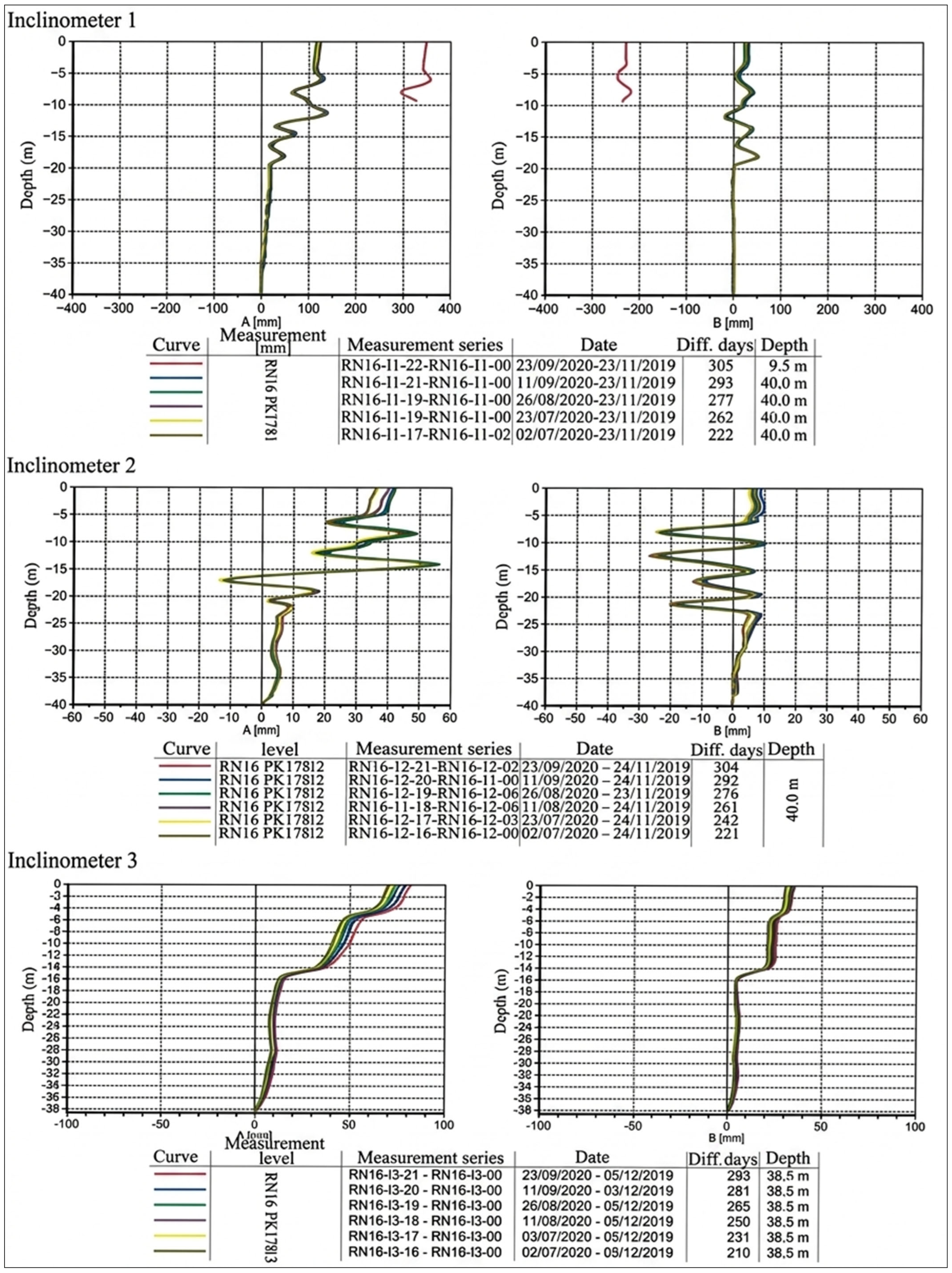
The inclinometer monitoring gave quantitative evidence of an active and deep-seated landslide. The main findings from the monitoring period are that: (i) Inclinometer SCP1-01 (on platform) showed substantial displacement with a shear failure of casing at the 9.5 m depth. This indicates a well-defined active slip surface. (ii) Inclinometer SCP1-02 (on platform) detected movement over the full depth range of 0- 20 m, therefore suggesting there is a broad shear zone. (iii) Inclinometer SCP1-03 (down slope); it recorded gradual movement between 0 and 16 m depth. The greatest amount of displacement occurred at 80 mm within the top 6 m, while the lowest recorded displacement was 60 mm from 6 to 16 m (Table 1).
Table 1 contains a summary of the inclined meter measurement of the ground up to 23 September 2020. The results of all measurements are consistent with each other and show evidence of a large deep-seated landslide with a failure zone exceeding 20 m below ground surface, supporting field observation and satellite imagery data (Table 2; Figure 15).

3.3. Geomechanical Parameters and Limit Equilibrium Modelling

Geomechanical design parameters were derived from a combination of pressiometric testing, laboratory identification, and back-analysis of the pre-failure slope geometry, assuming a limiting equilibrium state (Fs ≈ 1.0) at the time of the March 2020 failure event. Two lithotechnical units were defined: a weathered and fractured peridotite/colluvial mantle (Unit 1, 0–16 to 30 m bgs) constituting the sliding mass, and an intact serpentinised peridotite (Unit 2, below the detachment surface) forming the stable bearing stratum. The friction angle of Unit 1 (φ′ = 26°) was independently validated through the [21] pressiometric correlation (φ′ ≈ 25°), while its cohesion intercept was set to c′ = 18 kPa; Unit 2 parameters were derived exclusively from back-analysis (c′ = 65 kPa, φ′ = 39°). Limit equilibrium analyses were conducted using Talren V6 (Bishop’s simplified method) under two Eurocode loading situations, static saturated (EC7) and seismic pseudo-static with kh = 0.094 and kv = 0.047 (EC8, a gr = 1.37 m/s2), applied to both the pre-remediation and the Solution 3 remediated slope geometries. The pre-remediation slope was found to be at near-limiting equilibrium under static saturated conditions (Fs = 1.04) and unconditionally unstable under seismic loading (Fs = 0.81), confirming the validity of the adopted parameter set and the critical role of pore pressure mobilization in the failure triggering. The proposed Solution 3, slope regrading combined with a granular toe buttress (c′ = 0, φ′ = 42°) and surface drainage, achieves static and seismic safety factors of 1.82 and 1.24, respectively, satisfying Eurocode 7 and Eurocode 8 minimum requirements with safety margins of +82% and +24% above the limiting equilibrium state (Table 3 and Table 4).

4. Discussion

The instability at PK 178+000 represents a large-volume, deep-seated reactivation of a pre-existing landslide system, a failure typology well-documented in weak metamorphic and ultramafic terrains where successive tectonic, weathering, and anthropogenic stresses progressively erode the residual shear strength of structural discontinuities [3,22]. The borehole investigation (SCI-01 to SCI-03) reveals that the failure geometry is fundamentally translational in character, with a basal detachment plane deepening progressively from 16–17 m bgs at SCI-01 to 29–30 m bgs at SCI-03, reflecting the dip of the serpentinization front within the Beni Bousera peridotite massif [1]. This spatial pattern, a laterally deepening slip horizon following a lithological contact, is consistent with the translational landslide typologies described by [3] for sliding along structural discontinuities in foliated metamorphic rocks, and is directly analogous to deep-seated failures documented in the adjacent Rifian terrain by [2]. The inclinometer deflection profiles corroborate this interpretation: shear displacements are sharply localised at the identified slip horizons with negligible distributed deformation above, a signature indicative of brittle failure along a pre-existing mechanical boundary rather than progressive creep through the slope mass [22,23]. Two converging factors produced the critically low factor of safety that preceded reactivation. First, the inherently poor geomechanical quality of the slope-forming materials, highly weathered peridotite with an unfavourable structural dip, low effective cohesion (c′ = 18 kPa), and moderate friction angle (φ′ = 26°), placed the slope in a state of marginal stability even under dry conditions, a condition exacerbated by the additional driving forces induced by construction-related surcharge loading at the slope crest [24,25]. Second, the March 2020 extreme precipitation episode, delivering in excess of 170 mm over a few days against a monthly average of approximately 90 mm, generated rapid pore pressure build-up along the detachment surface, reducing the effective normal stress and mobilising the residual shear strength of the weathered peridotite matrix [4,26]. The back-analysis confirms that the combination of these two factors was sufficient to bring the slope to limiting equilibrium (Fs ≈ 1.04 under saturated static conditions), consistent with the hydro-mechanical failure model proposed by [8] for deep translational slides in weak rock terrain. Any viable remediation strategy must therefore simultaneously address both the structural driving mechanism, by reducing the gravitational load and increasing the passive resistance at the toe, and the hydrological triggering pathway, through systematic surface and subsurface drainage to prevent future pore pressure accumulation at the detachment surface. These dual imperatives informed the development and comparative evaluation of the three remediation solutions presented in Section 4.1, Section 4.2 and Section 4.3.

4.1. Solution 1: Terracing and Axis Realignment (Axis Shifting)

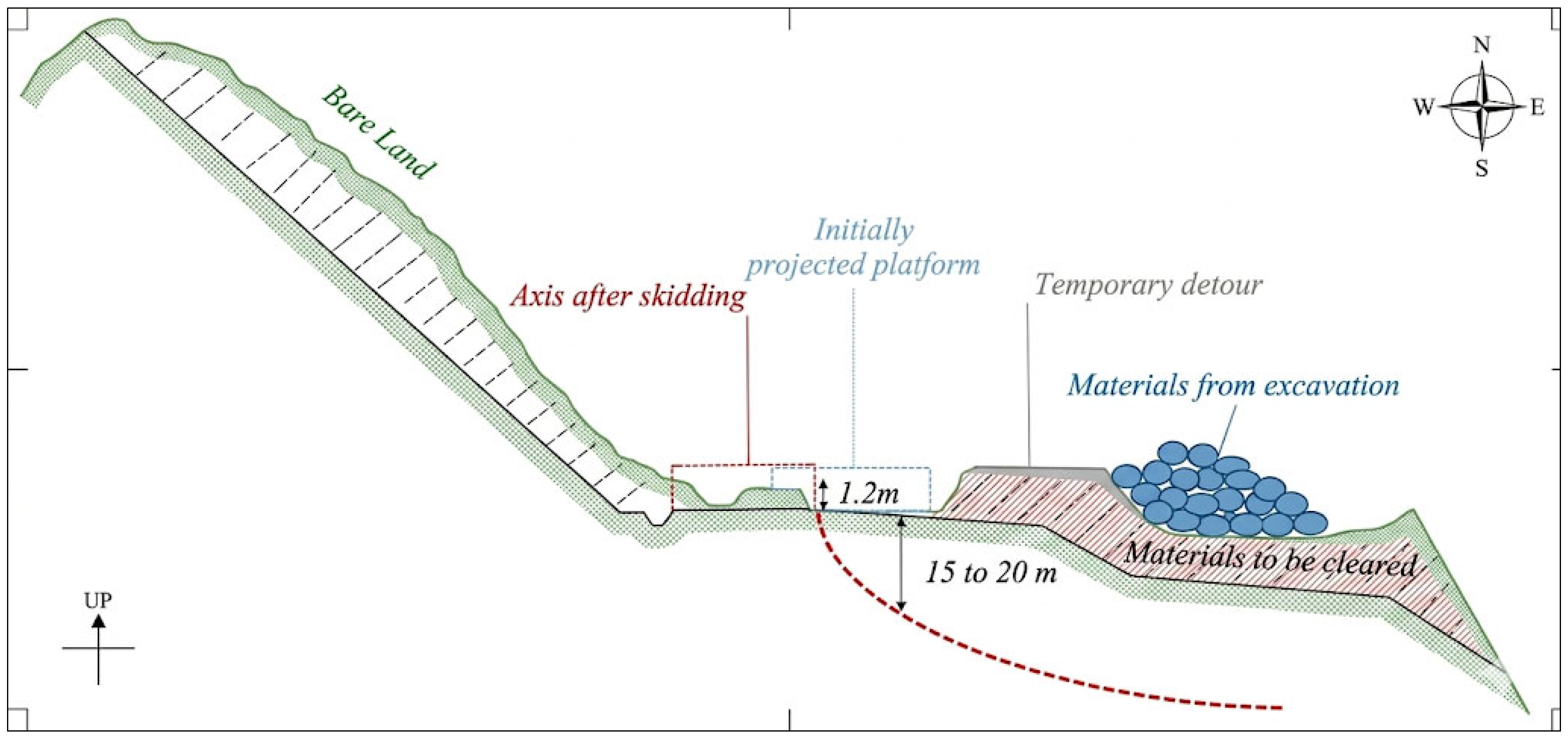
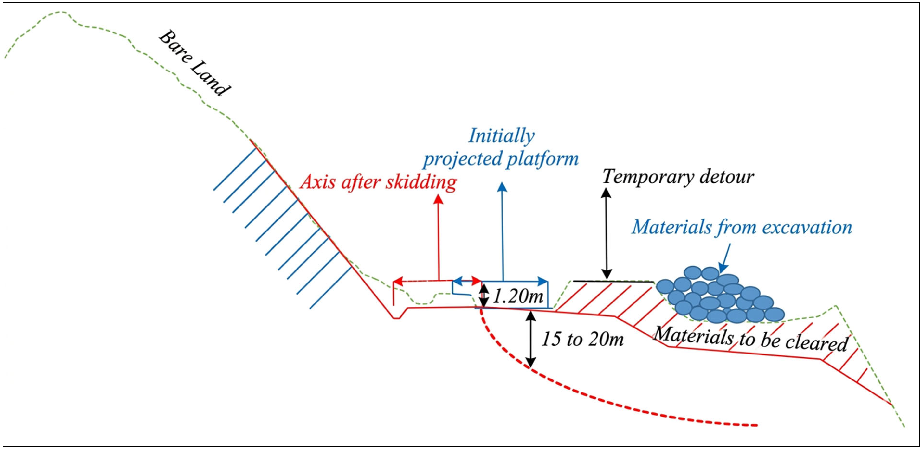
This geotechnical solution provides a series of measures to mitigate the driving force and stabilize the slope [27,28,29]. These measures include: (i) Shift the road centerline: The new platform could be established by shifting the road centerline (to the inland (upslope)) so that it is entirely supported by stable in situ ground away from the existing active slide mass. (ii) Remove surcharge: Surcharge materials will be removed from the downhill side to reduce loading on the head of the landslide. (iii) Re-profile slope: The existing slide mass will be graded to shallower and more stable slopes to prevent ponding of standing water and further movement of the slide mass. (iv) Manage drainage: A comprehensive drainage management system will be developed that includes crest ditches for surface water runoff and controlled downpipes to prevent water from being infiltrated into the slide mass (Figure 16).

4.2. Solution 2: Axis Realignment with Soil Nailing

The second version of this solution utilizes most of the first solution (reinforce slopes) in an effort to prevent the cut slope from slumping downhill using active reinforcement, thus reducing earthwork requirements [30,31] (Figure 17). There are three principal differences between the two present solutions: (i) Axis Shift; Remove surcharge—same as solution 1. (ii) Stabilize Cut Slope—rather than doing extensive terracing of the cut face of the slope, the slope will be stabilized with soil nails (grouted anchors) and a protective wire mesh therefore will create a steeper and stable cut face, thereby reducing the total footprint of the associated earthworks. (iii) Purge Active Zones—by removing the uppermost and most active portion of the landslide mass, it will reduce the weight or driving force causing the landslide mass to slide.

4.3. Solution 3: Piled Foundation

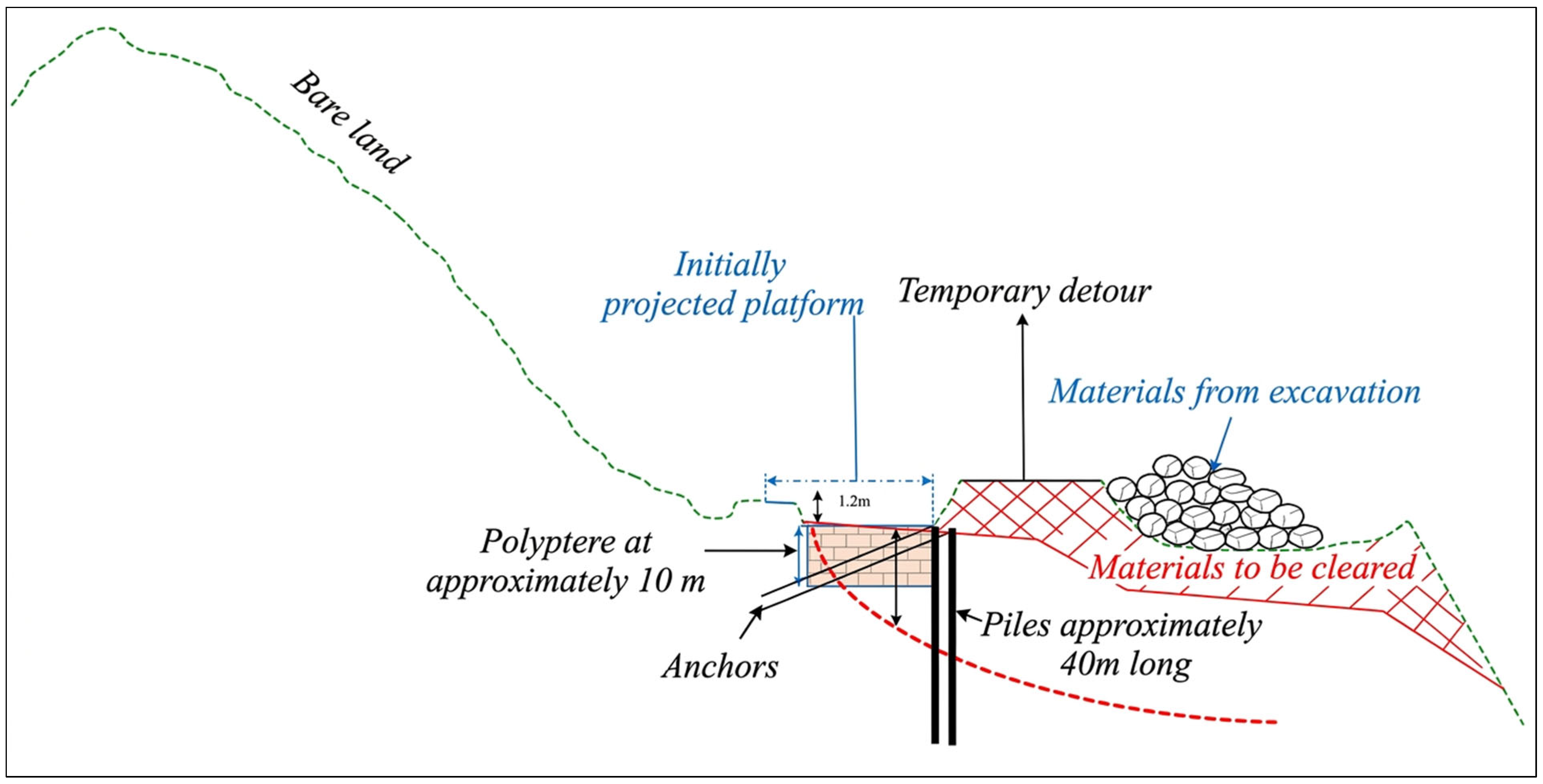
This solution suggests using a structural method to build a stiff barrier that maintains the road platform and intercepts the slip surface [32,33,34] (Figure 18). It is designed to resist the landslide forces directly. The proposed design includes: (i) Pile wall: Installation of two rows of large-diameter (1.20 m) bored piles, extending to a depth of 40 m to anchor well below the 20 m-deep failure zone. The piles would be spaced at 2 m. (ii) Anchorage: The pile wall would be reinforced with anchor ties (anchor bolts) to provide additional resistance against lateral earth pressures. (iii) Lightweight fill: An embankment of lightweight material would be used behind the pile wall to reduce the driving forces acting on the structure. (iv) Surcharge removal: As with the other solutions, removal of the deposited materials on the downslope side is essential.
To transition the proposed remediation measures from a conceptual layout to an engineered stabilization design, analytical sizing calculations were performed for the deep-seated anti-slip reinforced concrete pile system (Solution 3). The design parameters, consisting of a pile diameter (∅) of 1.20 m, a total length (L) of 40 m, and a center-to-center spacing (S) of 2.0 m, were validated against the active lateral landslide thrust and structural fixity requirements.
The total active landslide thrust acting per linear meter of the slope (Ea) was evaluated above the critical shear plane identified by the inclinometer monitoring (deforming between 9.5 m and 20.0 m depths). Under the most critical hydrogeological and pseudo-static seismic scenario (Kh = 0.07), the driving lateral force was calculated as:
Ea = 450 kN/m
To resist this driving force, the structural configuration of the anti-slip pile row was evaluated using the analytical model of Ito and [35] for plastic deformation and lateral soil pressure between adjacent piles. The theoretical ultimate resisting force (Ru) provided by the interacting 1.20 m diameter pile row at a 2.0 m spacing was determined to be:
Ru = 620 kN/m
Because Ru > Ea, the structural capacity of the piles provides an adequate margin of safety against catastrophic shear failure.
The selection of a 40 m total pile length is mechanically justified by the depth of the active sliding zone. In structural engineering geology, anti-slip piles must extend significantly past the lowermost failure plane into stable, unweathered bedrock to establish a rigid fixity condition (“fixed-end” boundary control). Based on a maximum detected shear displacement depth of 20.0 m, an embedment depth ratio of 1:1 (L = 20 m) was implemented into the unweathered peridotite core. This complies with standard criteria (L = 1.5 depth for highly weathered mantles) to safely distribute maximum bending moments and prevent plastic yielding of the anchoring bedrock layer [36,37].
Finally, the engineered system was cross-verified using Limit Equilibrium Method (LEM) numerical modeling in GeoStudio (SLOPE/W) to ensure compliance with international infrastructure standards (Eurocode 7/Moroccan National Regulations). The baseline targets required a minimum Factor of Safety (FoS) of 1.40 under static conditions and 1.15 under pseudo-static seismic loads. The post-remediation LEM simulations yielded a verified static FoS of 1.44 and a pseudo-static FoS of 1.18, confirming that the specified geometric dimensions provide robust long-term stabilization for the RN16 highway corridor.
The choice between these solutions involves a trade-off between cost, construction risk, long-term performance, and environmental impact. The terracing solutions (1 and 2) are geotechnically intuitive but require significant earthworks and land acquisition. The piled solution (3) is a more targeted structural intervention that minimizes earthworks but is technically complex and likely carries a higher initial cost. The final selection would require a detailed comparative analysis of these factors.

4.4. Hydrological Regime and Hydraulic Design Parameters

Due to the study area’s geographical proximity to the city of Tangier, and especially the similarity in rainfall patterns between the two areas, data from the Tangier weather station, which is regularly updated, are used to understand the climate of the region. The hydrological data used are derived from the analysis of rainfall records from Tangier provided by the National Meteorological Service. The parameters provided below are derived from the statistical analysis of a sample spanning approximately thirty years (Table 5). This section explicitly presents the Montana coefficients applied (a and b parameters calibrated for the coastal Mediterranean zone of Morocco), the computed peak runoff discharges (Qmax) for a 100-year return period, and how these hydraulic boundaries dictated the sizing of the trapezoidal concrete drainage ditches.
To ensure long-term structural slope integrity against hydroclimatic forcing, rainfall intensity was characterized using Montana’s empirical formulation: I = a × t−b. Using regional parameters calibrated for northern Morocco (a = 5.2, b = 0.65), the peak design discharge for a 100-year storm event was computed. This hydraulic volume directly informed the dimensional scale of the concrete surface channels.
Field data were collected during site visits. This data allowed us to observe water flow patterns on the site and their natural outlets. During these surveys, soil type, land use, and the slope of the watersheds near the route were identified to determine the proportion of infiltration and runoff. The soils encountered along the road are primarily schistose. These soils are highly susceptible to erosion and, consequently, landslides, and often have low permeability, particularly during heavy rainfall. Soil characteristics also influence vegetation cover. It is noted that the vegetation consists mainly of grassy areas and forested areas.

5. Conclusions

The investigation of the chronic instability at KP 178+000 of the RN16 highway has successfully diagnosed a deep-seated planar translational landslide reactivated by anthropogenic surcharge loading. Convergence of data collected from research conducted through historical document records, reconnaissance-by-foot over the land, aerial photography, and satellite images, as well as subsurface monitoring of soil and bedrock, has produced evidence of the mechanism for failure that is very robust. There are several major findings: (i) The evaluated site is located within an inherently unstable geologic environment consisting of weathered and fractured peridotite and has an unfavorable degree of dip concerning geological structure. (ii) The major triggering event that caused the large failure of 2019 was due to the uncontrolled placement of excavated materials at the bottom of the road as a result of slope stability related to the excavation of material from above. (iii) Inclinometer records indicate that the depth of the active failure to the present day is 20 m, thus indicating the need for a remediation measure that is deep and robust. (iv) Three viable remediation alternatives have been developed for the failure of the roadway, each involving geotechnical solutions involving the mass excavation and realignment of the roadway to a structural solution through the use of a deep piled foundation.
Managing excavated materials and accounting for the geological conditions before excavation are critical to the successful long-term stabilization of the RN16. This case study illustrates the potential for catastrophic and costly failure due to poor management and/or failure to account for pre-existing geological conditions during construction. Careful selection and implementation of one of the comprehensive and permanent solutions proposed in this case will help ensure that future construction of the RN16 can go beyond temporary and reactive measures into a permanent solution.

Author Contributions

Conceptualization, A.M. and B.B.; methodology, A.M. and B.B.; software, A.M.; validation, B.B., I.O., H.K.T. and M.M.; formal analysis, A.M. and B.B.; investigation, A.M.H.; resources, A.M.; data curation, A.M. and N.E.G.; writing—original draft preparation, A.M.; writing—review and editing, B.B., I.O. and T.B.; visualization, K.M.K.; supervision, B.B.; project administration, B.B.; funding acquisition, B.B. and K.M.K. All authors have read and agreed to the published version of the manuscript.

Funding

This research work was supported by the Deanship of Scientific Research at King Khalid University under grant number: RGP2/649/46.

Data Availability Statement

The original contributions presented in this study are included in the article. Further inquiries can be directed to the corresponding author.

Acknowledgments

The Authors extend their appreciation to the Deanship of Scientific Research at King Khalid University for funding this work through a large group Research Project under grant number: RGP2/649/46.

Conflicts of Interest

The authors declare no conflicts of interest.

Abbreviations

The following abbreviations are used in this manuscript:
RN16Road National
KPkilometer Point
MMeter
KmKilometer
MMMillimeter
SWSouthwest
NENortheast
LPEEPublic Testing and Research Laboratory
IDFIntensity Duration Frequency
IIntensity
TCTime of Concentration
CRRunoff Coefficient

References

  1. Chalouan, A.; Michard, A.; Kadiri, K.E.; Negro, F.; Lamotte, D.F.D.; Soto, J.I.; Saddiqi, O. The Rif belt. In Continental Evolution: The Geology of Morocco: Structure, Stratigraphy, and Tectonics of the Africa-Atlantic-Mediterranean Triple Junction; Springer: Berlin/Heidelberg, Germany, 2008; pp. 203–302. [Google Scholar] [CrossRef]
  2. Obda, O.; El Kharim, Y.; Obda, I.; Ahniche, M.; El Kouffi, A. Coastal rocky slopes instability analysis and landslide frequency-area distribution alongside the road network in west Mediterranean context (Northern of Morocco). Nat. Hazards 2024, 120, 3401–3428. [Google Scholar] [CrossRef]
  3. Hungr, O.; Leroueil, S.; Picarelli, L. The Varnes classification of landslide types, an update. Landslides 2014, 11, 167–194. [Google Scholar] [CrossRef]
  4. Iverson, R.M. Landslide triggering by rain infiltration. Water Resour. Res. 2000, 36, 1897–1910. [Google Scholar] [CrossRef]
  5. Huang, Y.; Jin, P. Impact of human interventions on coastal and marine geological hazards: A review. Bull. Eng. Geol. Environ. 2018, 77, 1081–1090. [Google Scholar] [CrossRef]
  6. Palanikkumar, D.; Alabdulkreem, E.; Alruwais, N.; Yahya, A.E. Coastal dynamics: Assessing erosion and progradation patterns in the Campeche coastal region using machine learning techniques for geological insights. J. S. Am. Earth Sci. 2025, 155, 105406. [Google Scholar] [CrossRef]
  7. Benzougagh, B.; Meshram, S.G.; Baamar, B.; Dridri, A.; Boudad, L.; Sadkaoui, D.; Mimich, K. Relationship between landslide and morpho-structural analysis: A case study in the Northeast of Morocco. Appl. Water Sci. 2020, 10, 175. [Google Scholar] [CrossRef]
  8. Springman, S.; Kienzler, P.; Casini, F.; Askarinejad, A. Landslide triggering experiment in a steep forested slope in Switzerland. In Proceedings of the 17th International Conference on Soil Mechanics and Geotechnical Engineering: The Academia and Practice of Geotechnical Engineering; IOS Press: Amsterdam, The Netherlands, 2009; Volume 2, pp. 1698–1701. [Google Scholar] [CrossRef]
  9. Conforti, M.; Ietto, F. An integrated approach to investigate slope instability affecting infrastructures. Bull. Eng. Geol. Environ. 2019, 78, 2355–2375. [Google Scholar] [CrossRef]
  10. Haundi, T.; Okonta, F. A systematic review of physical modelling techniques, developments, and applications in slope stability analyses. Indian Geotech. J. 2025, 55, 994–1016. [Google Scholar] [CrossRef]
  11. Chalouan, A.; Michard, A. The Alpine Rif Belt (Morocco): A case of mountain building in a subduction-subduction-transform fault triple junction. Pure Appl. Geophys. 2004, 161, 489–519. [Google Scholar] [CrossRef]
  12. Medrari, A.; Mastere, M.; Benzougagh, B. Geohazard assessment and ground movement mapping for cliff stabilization along RN16 in Chefchaouen, Morocco. Ecol. Eng. Environ. Technol. EEET 2025, 26, 86–102. [Google Scholar] [CrossRef]
  13. Ajraoui, A.; Chakiri, S.; Mansouri, H.; Ben Haddou, M.; Laassilia, O.; Labriki, A.; Soufi, A. Geotechnical analysis and stabilization of the Jebha Landslide: A case study from Morocco’s Mediterranean ring road. Civ. Eng. Archit. 2025, 13, 949–964. [Google Scholar] [CrossRef]
  14. Diamantis, K.; Khajevand, R.; Fereidooni, D. Assessing the geotechnical properties of peridotite rocks in dry and saturated conditions. Innov. Infrastruct. Solut. 2024, 9, 130. [Google Scholar] [CrossRef]
  15. Taj, B.; Mastere, M.; Benzougagh, B.; El Hilali, M.; Sassioui, S.; El Fellah, B. Geotechnical prospects and electrical tomography to study slope instability in the Rif Alboran Sea shoreline on the Mediterranean by-road (Northern Morocco). Ecol. Eng. Environ. Technol. 2024, 25, 138–151. [Google Scholar] [CrossRef]
  16. Florkowska, L.; Bryt-Nitarska, I.; Pilecka, E.; Białasek, K. Natural and Anthropogenic Risk Factors of Discontinuous Ground Deformations: A Conceptual Framework for Hazard Analysis: Part I—Predisposing Conditions. Appl. Sci. 2026, 16, 708. [Google Scholar] [CrossRef]
  17. Chapron, E.; Courp, T.; van Beek, P.; Tachikawa, K.; Jouve, G.; Chassiot, L.; Jézéquel, D.; Lajeunesse, P.; Zambardi, T.; Bard, E. Assessing Geological Hazards in a Changing World Through Regional Multidisciplinary Approaches to European Glacial Lakes (Northern Pyrenees, Northern and Western Alps). GeoHazards 2025, 6, 72. [Google Scholar] [CrossRef]
  18. Troncoso, L.; Echarri, F.J.T.; Pilatasig, L.; Ibadango, E.; Mateus, A.; Alonso-Pandavenes, O.; Bermeo, A.; Robayo, F.J.; Jost, L. Geological and Social Factors Related to Disasters Caused by Complex Mass Movements: The Quilloturo Landslide in Ecuador (2024). GeoHazards 2026, 7, 4. [Google Scholar] [CrossRef]
  19. Abdulahi, M.M.; Egli, P.E.; Bora, Z. Landslide Susceptibility Mapping in the Mount Elgon Districts of Eastern Uganda Using Google Earth Engine. GeoHazards 2026, 7, 50. [Google Scholar] [CrossRef]
  20. Nema, M.L.; Mahaman Saley, B.; Diedhiou, A.; Mugabe, A. Landslide Occurrence and Mitigation Strategies: Exploring Community Perception in Kivu Catchment of Rwanda. GeoHazards 2025, 7, 1. [Google Scholar] [CrossRef]
  21. Baguelin, F.; Frank, R.; Jezequel, J. Comparaison des résultats d’essais réalisés à l’aide de divers appareils autoforeurs. Bull. Liaison Lab. Ponts Chauss. 1978, 88–90. [Google Scholar]
  22. Leroueil, S.; Chandler, R.J. Natural slopes and cuts: Movement and failure mechanisms. Géotechnique 2001, 51, 197–243. [Google Scholar] [CrossRef]
  23. Petley, D.N.; Higuchi, T.; Petley, D.J.; Bulmer, M.H.; Carey, J. Development of progressive landslide failure in cohesive materials. Geology 2005, 33, 201–204. [Google Scholar] [CrossRef]
  24. Skempton, A.W.; Hutchinson, J. Stability of natural slopes and embankment foundations. In Proceedings of the 7th International Conference on Soil Mechanics and Foundation Engineering, Mexico City, Mexico, 25–29 August 1969; pp. 291–340. [Google Scholar]
  25. Duncan, J.M.; Wright, S.G.; Brandon, T.L. Soil Strength and Slope Stability; John Wiley & Sons: Hoboken, NJ, USA, 2014. [Google Scholar]
  26. Guzzetti, F.; Ardizzone, F.; Cardinali, M.; Rossi, M.; Valigi, D. Landslide volumes and landslide mobilization rates in Umbria, central Italy. Earth Planet. Sci. Lett. 2009, 279, 222–229. [Google Scholar] [CrossRef]
  27. Qu, J.K.; Zhu, Q.Y.; Qi, S.C.; Zhou, J.W. Instability mechanism of reservoir landslides under the combined effects of water level fluctuations and rainfall. Eng. Geol. 2025, 352, 108092. [Google Scholar] [CrossRef]
  28. Yuan, S.; Ding, B.; Guan, K.; Pérez-Rey, I.; Li, T.; Alejano, L.R. Analysis of a rock slope instability mechanism combining wedge and circular failure in a soft rock mass. Int. J. Coal Sci. Technol. 2026, 13, 49. [Google Scholar] [CrossRef]
  29. Xie, M.; Yin, L.E.; Wang, Z.; Xu, F.; Wu, X.; Xu, M. Numerical Simulation and Analysis of Micropile-Raft Joint Jacking Technology for Rectifying Inclined Buildings Due to Uneven Settlement. Buildings 2025, 15, 2485. [Google Scholar] [CrossRef]
  30. Alharbi, H.S. Geotechnical Controls on Land Degradation in Drylands: Indicators and Mitigation for Infrastructure and Renewable Energy. Sustainability 2025, 18, 242. [Google Scholar] [CrossRef]
  31. Kazmi, S.B.A.; Basharat, M.; Riaz, M.T.; Hameed, N.; Shafique, M.; Ahmed, K.S.; Ahmad, N. Characterization and deformation monitoring of ancient Lohar Gali Landslide, Muzaffarabad, Pakistan. Earth Surf. Process. Landf. 2026, 51, e70286. [Google Scholar] [CrossRef]
  32. Marwane, H.; Mohamed, E.H.; Mohammed, M.; Bensaid, M.; Kamal, B.; Mohammed, A.; Morabit, A. Soil nailing for slope stabilization: An overview. Interactions 2024, 246, 14. [Google Scholar] [CrossRef]
  33. Bahuguna, H. Landslides, hill slope instability, design of slope stabilization, techniques in vogue, and the way forward. Indian J. Geosci. 2025, 79, 347–372. [Google Scholar]
  34. Dong, B.C.; Chen, S.L.; Wang, Y.X.; Yang, T.; Ju, B.B. Research on the stability of anti-slip pile support structures for railway pile slopes. Symmetry 2022, 14, 2291. [Google Scholar] [CrossRef]
  35. Matsui, Y.; Kurita, T.; Yagi, M.; Okayama, T.; Mochida, K.; Date, Y. The formation and structure of copper (II) complexes with cyclodextrins in an alkaline solution. Bull. Chem. Soc. Jpn. 1975, 48, 2187–2191. [Google Scholar] [CrossRef]
  36. Zou, P.; Luo, G.; Bi, Y.; Xu, H. Dynamic response of pile–slab retaining wall structure under rockfall impact. Nat. Hazards Earth Syst. Sci. 2024, 24, 3497–3517. [Google Scholar] [CrossRef]
  37. Liu, G.; Luo, S.; Zhang, S.; Ma, K.; Bo, W.; Fan, H.; Dong, Z. Experimental Verifications and Applications of Discontinuous Deformation Analysis in Block-Type Rock Slope Failure and Movement Mechanisms. Rock Mech. Rock Eng. 2026. [Google Scholar] [CrossRef]
Figure 1. Location map of the study area.
Geohazards 07 00068 g001
Figure 2. Geological map of the Tétouan–Jebha section showing the complex nappe structures.
Geohazards 07 00068 g002
Figure 3. Hydrogeological map of the peridotite massif and its contact zones.
Geohazards 07 00068 g003
Figure 4. Extract from the Bou Ahmed geological map highlighting the steep dip in the vicinity of KP 178+000.
Geohazards 07 00068 g004
Figure 5. Flowchart of the methodology.
Geohazards 07 00068 g005
Figure 6. Open longitudinal tension cracks on the road platform, indicating the initiation of the 2019 failure. (A) General view of the RN16; (B) Focus on cracking.
Geohazards 07 00068 g006
Figure 7. Satellite image of the study area on 19 August 2019. (a): Dalot destroyed; (b): Materials from excavation; (c): Materials intended for the subgrade layer.
Geohazards 07 00068 g007
Figure 8. Photos showing the culvert affected by the landslide on the excavation side on 24 June 2021.
Geohazards 07 00068 g008
Figure 9. Temporal evolution of the landslide affecting the RN16. (a): on 30 August 2008, in its natural state before the road was built and the false embankment added. (b): on 7 August 2010. (c): on 15 December 2015. (d): on 19 December 2017. (e): on 19 August 2019.
Geohazards 07 00068 g009
Figure 10. Comparison of the shoreline in 2008 (initial state) (a) and the current state (b), showing significant bulging indicative of a deep, massive landslide.
Geohazards 07 00068 g010
Figure 11. The location map of the three survey points on RN16.
Geohazards 07 00068 g011
Figure 12. Lithological section of the exploratory borehole (SCI-01).
Geohazards 07 00068 g012
Figure 13. Lithological section of the exploratory borehole (SCI-02).
Geohazards 07 00068 g013
Figure 14. Lithological section of the exploratory borehole (SCI-03).
Geohazards 07 00068 g014
Figure 15. Results of inclinometers installed to monitor landslides.
Geohazards 07 00068 g015
Figure 16. Schematic principle of Solution 1, involving shifting the road axis upslope and re-profiling the landslide mass.
Geohazards 07 00068 g016
Figure 17. Schematic principle of Solution 2, combining axis realignment with soil nailing for the upslope cut.
Geohazards 07 00068 g017
Figure 18. Schematic principle of Solution 3, featuring a deep-piled foundation with anchors to stabilize the slope.
Geohazards 07 00068 g018
Table 1. Summary table of inclinometers installed to monitor landslides.
N° of InclinometersDepthDate of InstallationObservation
I 140 m20 November 2019Fractured at 9.50 m
I 240 m23 November 2019
I 338.50 m29 November 2019
Table 2. The results of inclinometer measurements.
Study AreaInclinometersDepthDate of InstallationMaximum Displacement (mm)Observation
RN16 KP 178+00I 140 m21 January 2019350 (A+);
150 (B+)
Sheared at 9.50 m between 11 September 2020 and 23 September 2020.
I 240 m4 February 201955 (A+);
28 (B−)
Movement between 0 and 20 m.
I 338.50 m23 February 201980 (A+);
38 (B+)
Progressive movement between 0 and 16 m with a maximum displacement of 80 mm between 0 and 6 m and a maximum displacement of 60 mm between 6 m and 16 m
Table 3. Geomechanical design parameters adopted in the limit equilibrium stability analyses.
Material Unitc′ (kPa)φ′ (°)γ (kN/m3)Piezometric ConditionParameter Source
Weathered peridotite/colluvium (Unit 1)182620–21Saturated (hw = H, static) Partial (hw = 0.5 H, seismic)Back-analysis [21]
Intact serpentinised peridotite (Unit 2)653926–27DrainedBack-analysis
Granular buttress fill, Solution 3 (design)04221DrainedMaterial specification (GTR Class R2)
c′: effective cohesion; φ′: effective friction angle; γ: bulk unit weight; hw: piezometric height; H: thickness of the sliding mass unit.
Table 4. Limit equilibrium stability analysis results for the pre-remediation and Solution 3: remediated slope at PK 178+000.
Slope
Configuration
Loading ConditionFs ComputedFs Minimum RequiredSafety Margin (%)
Pre- remediationOriginal cut—failed geometryStatic
(saturated)
1.041.50 (EC7 GEO)−31%
Original cut—failed geometrySeismic
(kh = 0.094)
0.811.10 (EC8 Seismic)−26%
Solution 3 (remediated)Regraded slope + toe buttress + drainageStatic
(saturated)
1.821.50 (EC7 GEO)+82%
Regraded slope + toe buttress + drainageSeismic
(kh = 0.094)
1.241.10 (EC8 Seismic)+24%
Table 5. Montana Parameters (Tangier Station).
Montana’s Formula: I = a × t−b
T (year)51020100
a4.687.498.5811.05
b−0.631−0.619−0.617−0.614
Disclaimer/Publisher’s Note: The statements, opinions and data contained in all publications are solely those of the individual author(s) and contributor(s) and not of MDPI and/or the editor(s). MDPI and/or the editor(s) disclaim responsibility for any injury to people or property resulting from any ideas, methods, instructions or products referred to in the content.