


Abstract
Unmanned aerial vehicles (UAVs) are widely used for monitoring and payload transport; however, their application in autonomous physical interaction remains limited due to payload constraints, stability challenges, and the complexity of integrating manipulation systems. This study presents the design and development of a lightweight foldable robotic arm based on the ten-bar Kempe Kite Inversor II linkage for UAV aerial manipulation. The mechanism generates precise straight-line motion using a single degree of freedom. Kinematic modeling and simulation validated a maximum end-effector reach of approximately 0.42 m. Structural optimization using additive manufacturing and honeycomb cellular architectures significantly reduced system weight while maintaining mechanical reliability. A passive compliant gripper, counterbalance mechanism, onboard storage net, and landing gear were integrated to evaluate the arm in a practical harvesting scenario using cherries as the test object. The final integrated system weighs 0.351 kg during operation, remaining approximately 16% below the experimentally determined UAV payload limit of 0.4185 kg. Proof-of-concept flight demonstrations confirmed successful aerial grasping of cherries, validating the feasibility of the proposed lightweight manipulation approach for agricultural applications.
1. Introduction
Agricultural automation has become increasingly important as global food demand continues to rise alongside labor shortages and the need for higher productivity in modern farming systems [1,2,3,4]. Robotics has emerged as a promising solution for improving agricultural efficiency, reducing manual labor, and enabling precision farming operations. While autonomous ground vehicles (AGVs) have been widely explored for agricultural tasks such as harvesting, monitoring, and material transport, their mobility remains constrained by terrain conditions, crop spacing, and field accessibility [1,2,5]. In contrast, unmanned aerial vehicles (UAVs) offer significantly greater operational flexibility due to their ability to rapidly navigate complex environments and access hard-to-reach locations [6]. Recent advancements in UAV platforms and lightweight robotic systems have demonstrated strong potential for crop monitoring, precision treatment, and harvesting applications [7,8,9,10]. However, most existing UAV systems primarily focus on sensing, imaging, spraying, or payload transport rather than direct physical interaction with crops. The integration of robotic manipulators into UAV platforms remains limited due to payload restrictions, reduced flight endurance, stability challenges, and the complexity of actuator integration and control [6,7,8]. Existing studies have largely emphasized control strategies, simulation frameworks, or simplified prototypes, with limited focus on fully integrated mechanical manipulation systems [9,10,11,12,13,14,15]. Several aerial manipulation systems have been proposed for agricultural applications; however, most remain limited in operational capability. Many designs rely on downward-mounted manipulators that restrict workspace accessibility in dense foliage or variable crop environments [16,17]. In addition, most systems are designed for single-object interaction and lack onboard storage capabilities, requiring repeated repositioning or return flights after each grasping task [18,19,20,21,22,23,24]. Integrating storage further introduces challenges related to payload capacity, center-of-mass shifts, and flight stability, particularly under real agricultural operating conditions involving wind disturbances and repeated harvesting operations [25,26].
Another critical challenge is achieving reliable extension, grasping, storage, and retraction while minimizing mechanical complexity. Multi-actuator systems often increase mass, energy consumption, and control requirements, limiting scalability for practical agricultural deployment [27]. By enabling multiple harvesting operations without repeated landing cycles, such systems can improve operational efficiency and provide a scalable framework for future precision agriculture applications, including crop sampling, selective harvesting, and targeted treatment of high-value crops [28].
This study focuses on the design, kinematic analysis, optimization, and development of a lightweight foldable robotic arm based on the ten-bar Kempe Kite Inversor II linkage for UAV aerial manipulation. The mechanism generates precise straight-line motion using a single degree of freedom and was selected for its favorable combination of compactness, structural rigidity, and low actuation complexity. Supporting subsystems, used in integration and proof-of-concept validation, include a passive compliant gripper, counterbalance mechanism, onboard storage system, and landing gear. These were integrated to evaluate the arm’s performance in a practical harvesting scenario using cherries as the test object. The work is supported through kinematic modeling, singularity analysis, structural optimization using additive manufacturing, and proof-of-concept flight testing.
2. Materials and Methods
The objective of this work is to develop a UAV-integrated robotic platform capable of performing multiple grasping operations during a single flight mission. The system is specifically designed for handling small and delicate agricultural products, such as cherries, while operating under strict payload, energy, and flight stability constraints.
The proposed platform performs a complete operational cycle consisting of: (i) extension of a foldable robotic arm beyond the UAV frame, (ii) passive grasping of the target object, (iii) transfer of the object into an onboard storage container, and (iv) retraction of the mechanism into a compact configuration for stable flight. This workflow reduces repeated landing cycles and improves operational efficiency during harvesting or sampling tasks.
The overall architecture consists of mechanical and electromechanical subsystems. The mechanical subsystem includes a foldable robotic arm based on a ten-bar Kempe Kite Inversor II linkage that generates straight-line motion with a single degree of freedom, a passive compliant gripper for handling delicate objects, a counterbalance mechanism for maintaining stability during arm deployment, a lightweight storage container for collecting multiple objects, and a landing gear structure that provides sufficient ground clearance.
The electromechanical subsystem consists of a linear actuator coupled with a Scotch Yoke mechanism that simultaneously drives both the robotic arm and counterbalance system using a single input. A relay-based wireless control module and battery system enable bidirectional actuation while reducing control complexity.
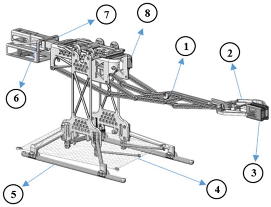
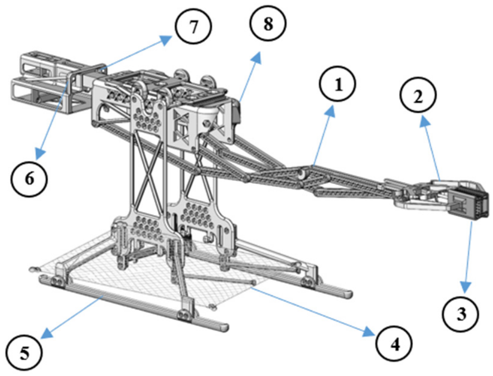
The integrated design emphasizes lightweight construction, minimal actuation requirements, and operational efficiency for aerial manipulation tasks. A final design model of the complete system with labeled components is shown in Figure 1 and Table 1.
Figure 1.
Overview of the UAV-integrated robotic manipulation system with labeled components.
Table 1.
Component label names for Figure 1.
3. Results
3.1. Design and Kinematic Analysis of the Foldable Robotic Arm
The development of a lightweight, foldable robotic arm suitable for integration with UAVs requires a mechanism that provides precise linear extension using minimal actuation. This section presents the analytical foundation and design methodology used to create the proposed arm. The process begins with the selection of a suitable linkage configuration based on design requirements and mechanical constraints. The chosen mechanism is then analyzed for mobility, followed by the formulation of forward and inverse kinematics to define its motion behavior. Finally, the singularity conditions are derived to ensure continuous and stable operation within the allowable range of motion.
3.1.1. Mechanism Selection and Concept Development
The design of a foldable robotic arm for integration with UAVs must satisfy multiple, often conflicting objectives. The system must be lightweight, compact, and employ minimal actuation to reduce both mass and control complexity, while still achieving sufficient reach without compromising the stability of the aerial platform. These constraints arise from the UAV’s limited payload capacity and its sensitivity to shifts in the center of mass during manipulation tasks. Accordingly, a systematic selection process was conducted to identify a mechanism that achieves a balanced trade-off among actuation simplicity, motion linearity, compactness, manufacturability, and ease of integration.
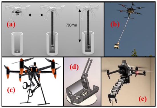
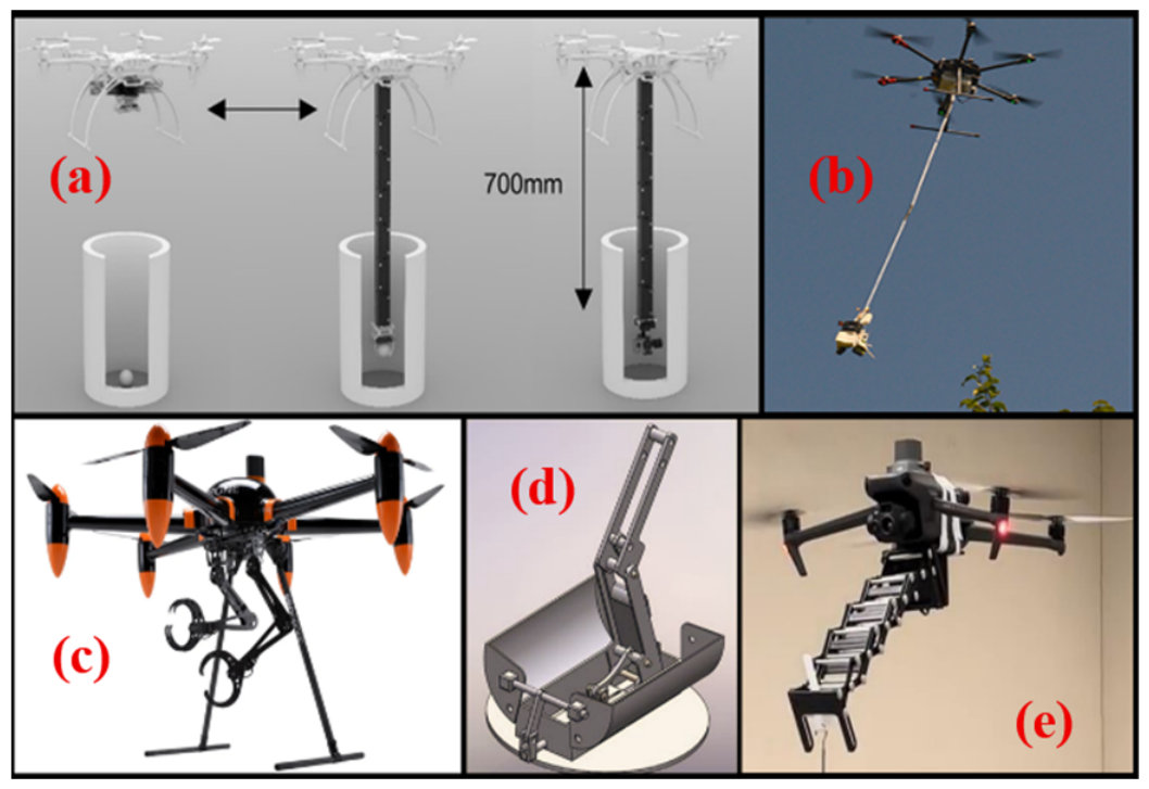
A review of candidate mechanisms for aerial manipulation, illustrated in Figure 2 [29], highlights several representative architectures explored in prior work:
Figure 2.
Alternative options for the arm mechanism for aerial drones, which include (a) Origami arm; (b) Cable-driven arm; (c) Multi-degree-of-freedom manipulator; (d) Retractable telescopic arm; (e) Scissor mechanism [29].
- (a)
- Origami-based arms, characterized by lightweight folding panels and high compactness, but limited by low structural rigidity.
- (b)
- Cable-driven systems, offering large reach with minimal mass, but constrained by low positional accuracy and tension management complexity.
- (c)
- Commercial multi-degree-of-freedom manipulators, enabling versatile motion, but incurring excessive mass and control burden.
- (d)
- Retractable linkages employing telescopic motion, extending reach at the expense of increased friction losses and structural complexity.
- (e)
- Scissor mechanisms, providing symmetric extension with a single actuator, but susceptible to lateral deflection.
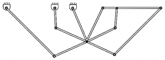
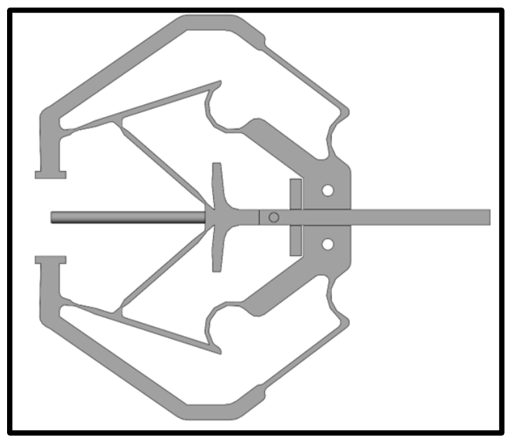
While these approaches address specific aspects of the design space, none simultaneously satisfy the combined requirements of minimal actuation, structural rigidity, compact folding, predictable straight-line motion, and effective UAV integration. To address these limitations, this work proposes a ten-bar straight-line mechanism based on the Kempe Kite Inversor II as the core of the foldable robotic arm (Figure 3).
Figure 3.
Ten-bar Kempe Kite Inversor II straight-line mechanism.
This configuration was selected because it offers a superior balance of key performance metrics critical for UAV applications. Compared to scissor mechanisms (which provide symmetric extension with a single actuator but suffer from lateral deflection and lower stiffness), telescopic arms (which achieve large reach but introduce high friction, structural complexity, and increased mass), cable-driven systems (which offer low mass and large workspace but suffer from low positional accuracy and challenging tension management), origami-based designs (highly compact but limited by low structural rigidity), and commercial multi-DOF manipulators (highly versatile but excessively heavy with high actuator count and control complexity), the proposed ten-bar Kempe Kite Inversor II linkage provides:
- Precise straight-line motion using only revolute joints and a single actuator,
- Excellent folding ratio (extension-to-fold ratio ≈ 2:1), allowing full retraction within the UAV frame,
- High structural stiffness relative to mass through its symmetric coupled architecture,
- Low actuator count (single DOF), minimizing mass, power consumption, and control complexity,
- Favorable UAV integration by maintaining balanced torque distribution and enabling the end-effector to extend beyond the propeller plane while retracting compactly to preserve aerodynamic stability and center-of-mass control.
To the best of the authors’ knowledge, this class of mechanism has not been previously applied to UAV-based manipulation systems. This work represents the first implementation of the Kempe Kite Inversor II linkage in a UAV-mounted system with integrated passive gripper and onboard storage. The present design further distinguishes itself through comprehensive singularity analysis and honeycomb-based structural optimization tailored for minimal mass under UAV payload constraints.
The selected configuration is based on the Kempe Kite Inversor II, a ten-bar planar linkage that can be interpreted as a higher-order coupled four-bar system capable of generating an exact straight-line trajectory through geometric coupling of its revolute joints. This mechanism belongs to the broader class of Kempe Inversors, which produce rectilinear motion without the use of prismatic joints. Its principal advantage lies in its ability to transform a single rotary input into coordinated motion of all links, yielding high kinematic repeatability and a compact folding configuration.
For UAV applications, the Kempe-based linkage is parameterized to achieve an extension-to-fold ratio of approximately 2:1, enabling the end-effector to extend beyond the propeller plane while retracting fully within the vehicle frame to maintain aerodynamic efficiency. The mechanism’s single degree of freedom simplifies control and enables direct actuation using a compact rotary servo or equivalent actuator.
Overall, this design selection ensures that the proposed foldable robotic arm exhibits predictable kinematic behavior, low actuation complexity, and manufacturable simplicity, thereby providing a robust foundation for subsequent mobility and kinematic modeling.
3.1.2. Mobility Analysis
The degree of freedom (DOF) of the proposed mechanism is determined using the Chebychev–Grübler–Kutzbach (KGC) criterion. Since all revolute joint axes are parallel, the mechanism operates in a planar configuration. Accordingly, the mobility of the planar system is given by:
where is the number of links, is the number of joints, and is the DOF of the joint.
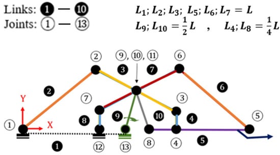
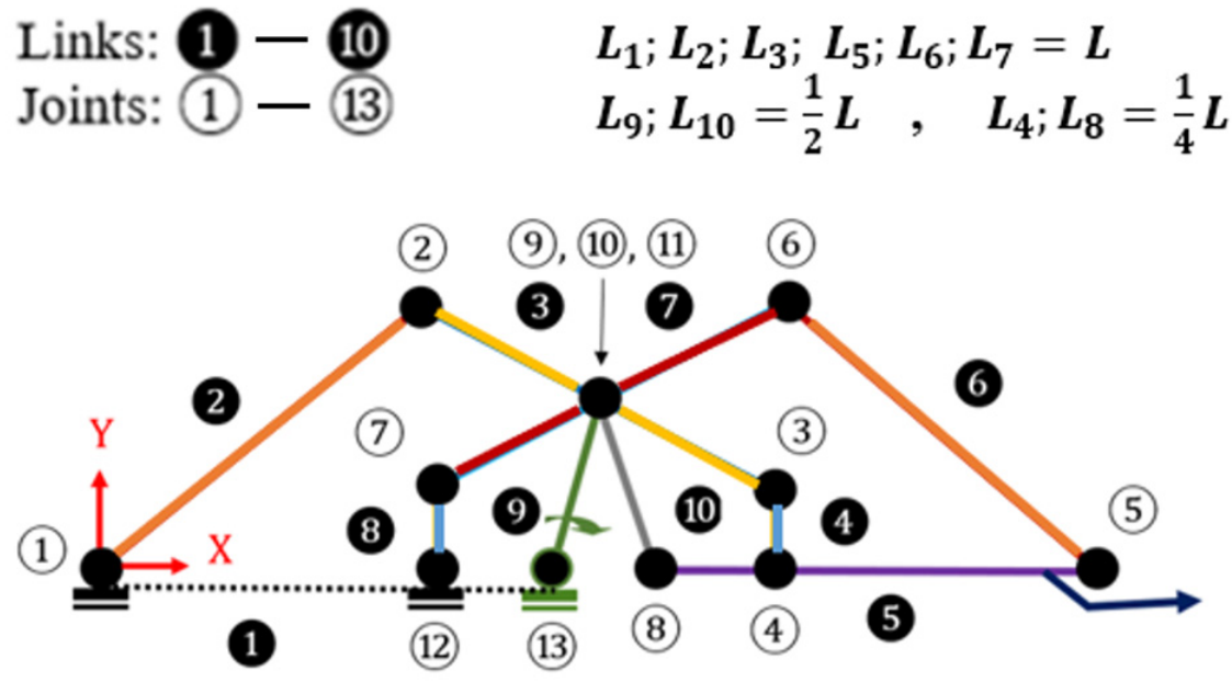
The kinematic sketch of the Kempe Kite Inversor II is shown in Figure 4. This mechanism consists of ten links () connected through thirteen revolute joints (), yielding:
Figure 4.
Kinematic diagram of the Kempe Kite Invertor II. The parameter “L” denotes the length of the longest link(s).
Hence, the mechanism has a single degree of freedom, confirming that one actuator can control the entire system. This simplifies control, reduces weight, and ensures deterministic motion transmission—each input position uniquely defines the configuration of all dependent links.
3.1.3. Forward Kinematic Formulation
To describe the kinematic relationship between the input link and the end-effector of the proposed ten-bar mechanism, a vector-loop formulation is employed. For the Kempe Kite Inversor II, the number of independent loops is determined from the number of links and joints as:
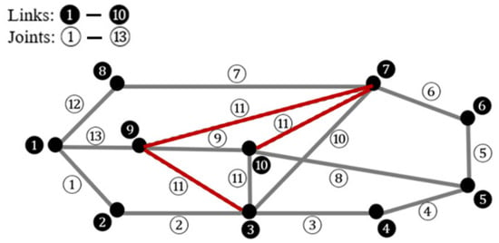
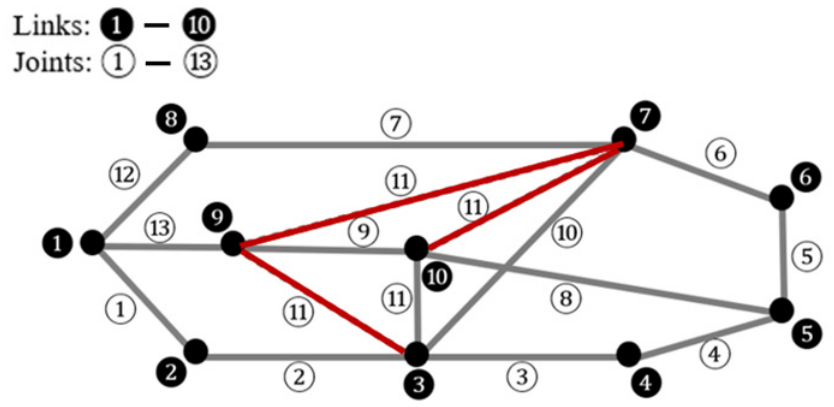
Accordingly, four independent loops exist in this mechanism. To systematically identify these loops in the multi-loop topology, an adjacency matrix and the corresponding graph representation are constructed, as shown in Equation (4) and Figure 5. The adjacency matrix is defined based on link connectivity, assigning a value of 1 if two links are connected by a joint and 0 otherwise. The associated graph is then formed by representing links as nodes and joints as edges. Independent cycles are identified by tracing the minimal closed paths in this graph.
Figure 5.
Adjacency Graph for the Kinematic Sketch, highlighting the coupled pairs.
Joints 9, 10, and 11 form a coupling cluster that interconnects multiple kinematic sub-chains. Specifically, links 9 and 10 are connected at joint 9, while links 7 and 3 are connected at joint 10. Joint 11 further couples these pairs, linking links 9–3, 9–7, 10–3, and 10–7, thereby closing the multi-loop structure. The highlighted connections in Figure 5 illustrate these coupling relationships.
1 2 3 4 5 6 7 8 9 10 11 12 13
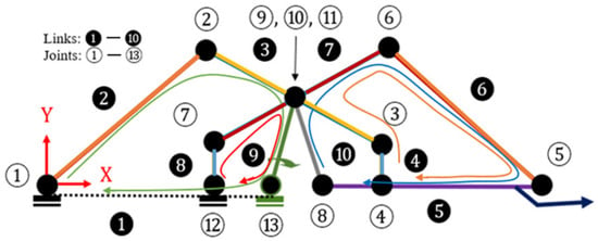
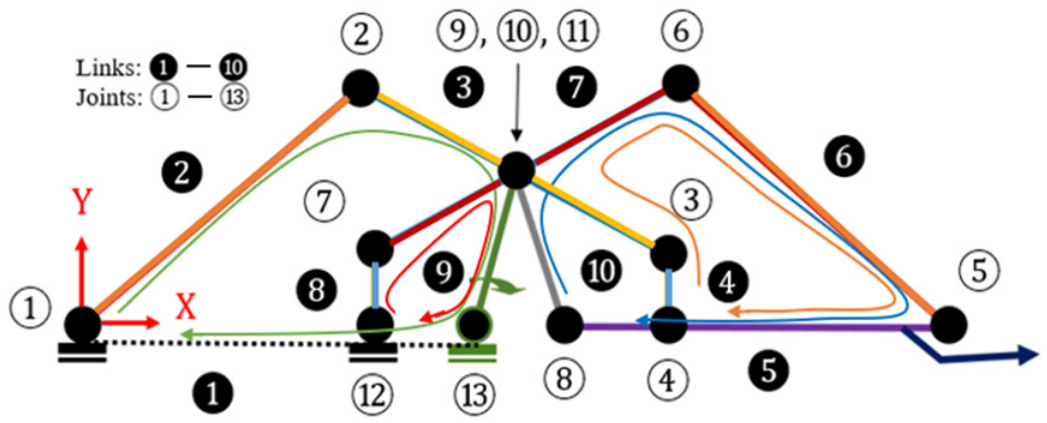
Using a cycle-basis approach, the independent loops of the mechanism were identified, ensuring complete kinematic coverage with the minimal number of loop-closure equations. A vertex-degree analysis was employed to assign incident links to each joint, and four independent loops were selected and ordered by increasing path length (Table 2). These loops were subsequently verified and illustrated on the kinematic sketch diagram (Figure 6).
Table 2.
Four Independent Loops.
Figure 6.
Independent loops defined on the kinematic diagram of the linkage system.
Each loop has been expressed in vector form as:
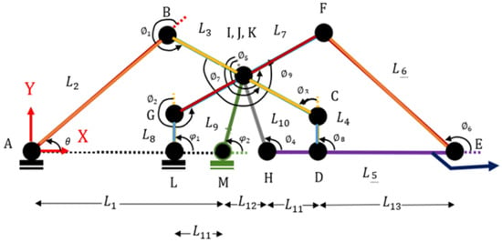
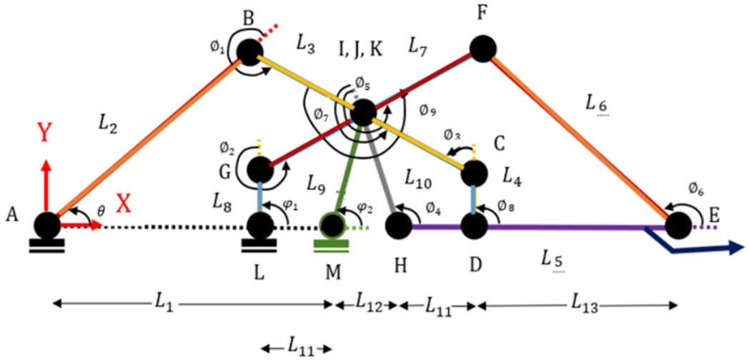
where represents the position vector of the link. Expanding the loop-closure equations in two-dimensional Cartesian coordinates yields eight scalar equations, as summarized in Table 3. The geometric definitions of link lengths and the corresponding joint angles are illustrated in Figure 7 (where θ is the input angle, φ and ∅ denote dependent joint angles). Positive angles are measured counterclockwise from the positive x-axis, consistent with the coordinate system shown (Figure 7). These equations were solved numerically in MATLAB® and validated against both CAD models and GIM simulation results.
Table 3.
Loop Equations.
Figure 7.
Defining the Link Lengths and Needed Angles.
Among the geometric parameters, all link lengths (except ) are known. The parameter does not appear in the loop-closure equations and is not independent; it is a function of and . In addition, is the known input angle. Therefore, the unknown set consists of ten angular variables: and . By introducing two symmetry-based angular constraints, the system is solvable with eight loop-closure equations and eight unknowns. The two symmetry-based angular constraints applied are from the product of the other angles, and . These constraints arise from the symmetric geometry of the isosceles linkages in the Kempe Kite Inversor II mechanism (as shown in Figure 7) and reduce the number of independent unknowns from ten to eight while preserving the accuracy of the model.
Although the proposed mechanism is a closed-chain linkage, the Denavit–Hartenberg (DH) convention is applied to an equivalent open-chain kinematic path from the base (Joint A) to the end-effector (Joint E). This specific path was carefully selected because it follows a continuous sequence of links that accurately represents the motion of the end-effector while respecting the kinematic constraints of the multi-loop topology. By transforming the closed-chain system into an equivalent open-chain representation along this path, the DH method enables straightforward computation of the end-effector pose using successive homogeneous transformation matrices.
This hybrid modeling approach is a well-established technique in the kinematic analysis of complex multi-loop mechanisms. It provides computational convenience and facilitates numerical validation of the end-effector position against the vector-loop results and simulation software (CAD and GIM). Importantly, the primary kinematic relationships, loop-closure equations, and singularity analysis remain derived from the geometrically exact vector-loop formulation. The DH representation therefore serves as a complementary tool for forward kinematics calculation and verification rather than the foundational model. This combination offers both analytical rigor from the vector-loop equations and practical computational efficiency from the DH formulation.
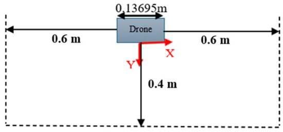
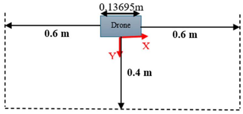
The configuration space (C-space) of the ten-bar mechanism is one-dimensional, governed by the single variable θ, which varies from 1° to 60° based on kinematic limits and angular constraints [29]. The task space is two-dimensional , while the resulting workspace corresponds to a straight-line trajectory along the -direction. The operational boundary of this workspace, constrained by UAV sensing and physical limits, is illustrated in Figure 8.
Figure 8.
Task Space Definition for the Mechanism.
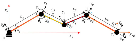
The coordinate frames were assigned sequentially along a selected kinematic chain of the linkage, as illustrated in Figure 9, following the standard DH convention. Each transformation consists of a sequence of rotations and translations that describe the pose of one frame relative to the preceding frame. A kinematic path was defined from Joint A to Joint E to obtain an equivalent open-chain representation consistent with the DH formulation. Because the mechanism operates in a planar configuration, all twist angles (α) and joint offsets (d) are zero. The resulting DH parameters are summarized in Table 4.
Figure 9.
Path Representation to the End-Effector.
Table 4.
DH Parameters.
Using these parameters, the rotational and translational transformations were combined to form the homogeneous transformation matrix. For planar motion, the formulation reduces to a 3 × 3 homogeneous transformation, obtained by eliminating the out-of-plane components of the full 4 × 4 representation. The complete transformation matrix was derived symbolically in MATLAB® 2023b, yielding a closed-form expression for the end-effector frame relative to the ground link. The position vector of the end-effector was extracted from the translational components of this matrix.
To validate the analytical model, a MATLAB® solver was developed to evaluate multiple input configurations and was compared with both CAD and GIM simulation results. Assuming the longest link length and an input angle , the MATLAB® model predicted an end-effector position of and , which is in excellent agreement with the CAD model. The kinematic simulation software GIM [30] was also used to independently verify the linkage motion, confirming the same straight-line trajectory and positional consistency across multiple configurations (Figure 10). These results validate the correctness of the symbolic formulation and confirm that the mechanism’s workspace follows a rectilinear path along the -axis, extending approximately from to , while preserving geometric scalability with respect to the chosen value of .
Figure 10.
Position Analysis of Kempe Kite Inversor II using GIM [30].
3.1.4. Inverse Kinematics
The inverse kinematics (IK) analysis determines the input angle required to achieve a specified end-effector position along the rectilinear workspace. Since the Kempe Kite Inversor II mechanism has a single degree of freedom, the inverse problem reduces to finding the input angle corresponding to a given Cartesian position . For the ideal straight-line motion of the mechanism, , and the mapping can be expressed as:
From the forward kinematic model, the end-effector position along the x-direction is given by:
where represents the variable horizontal span defined by the internal isosceles linkage, which varies with the input angle .
Geometrically, since , the total linear reach of the mechanism varies between (fully retracted) and (fully extended). Using the validated kinematic model, the maximum extension of the prototype with is:
This corresponds to a physical workspace limit of approximately . The characteristic link length was selected for the prototype to remain within the UAV body envelope and avoid interference with onboard sensors in the retracted configuration. Maintaining the link length at or below the drone body length allows the sensing system to operate without modification or deactivation.
The prototype was intentionally designed at this scale to reduce mass and to experimentally validate the kinematic model within a controlled environment. While larger link lengths could extend the reachable workspace, they would exceed the geometric constraints of the selected UAV platform and may interfere with sensing and operation.
To confirm these relationships, a MATLAB® inverse-kinematics solver was developed using the symbolic forward-kinematics equations. For a prescribed end-effector position , the solver iteratively computes the corresponding input angle . For the prototype configuration , the inverse model reproduces the forward-kinematic result at , yielding and .
The inverse-kinematic solution can also be expressed geometrically using the law of cosines for the internal isosceles linkage, which defines the variable segment . Substituting this relation into Equation (15) gives:
which provides an analytical check of the MATLAB® results. Both the analytical and numerical solutions confirm that the end-effector follows a rectilinear path along the x-axis, validating the inverse-kinematic formulation and demonstrating geometric scalability of the mechanism.
3.1.5. Singularity Analysis
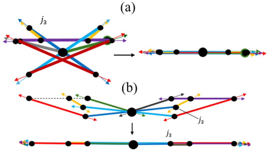
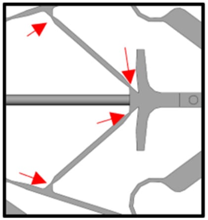
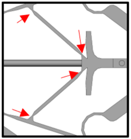
A singularity in a closed-loop mechanism occurs when the linkage loses mobility or becomes kinematically indeterminate due to link alignment or coincident joint axes. For the proposed ten-bar mechanism (Kempe Kite Inversor II), singular configurations were first identified using a geometric tangent-line method [31,32,33]. In this approach, the mechanism is virtually separated at a selected joint, and the relative motion between the resulting sub chains is examined. A singularity occurs when the relative motion becomes indeterminate due to link alignment, leading to a loss of instantaneous mobility.
Applying this method revealed two distinct singular configurations (Figure 11): a fully retracted configuration, where the links fold onto one another, and a fully extended configuration, where multiple links align along the -axis. These configurations occur at the extreme input-angle limits, and , and correspond to collinear arrangements of several revolute joints, indicating the presence of geometric singularities.
Figure 11.
Mechanism at (a) fully retracted and (b) fully extended singular configurations showing tangent alignment.
To verify these conditions analytically, the Jacobian matrix was derived from the differentiated loop-closure equations. The velocity relationships can be expressed as:
where is the Jacobian matrix containing the angular-velocity coefficients, is the vector of joint rates, and represents the known input terms. A singular configuration occurs when:
Substituting the aligned-link conditions into the Jacobian, the determinant evaluated numerically in MATLAB® approaches zero (), confirming that the mechanism becomes singular at both the fully retracted and fully extended configurations. These analytical results are consistent with the geometric interpretation.
At these singular configurations, the mechanism exhibits loss of mobility or poor motion transmission, where input motion produces negligible or ill-conditioned end-effector displacement. To ensure stable operation, the input angle is restricted to the range thereby avoiding singular configurations. Mechanical stops or software-based actuator limits are implemented to enforce this range. Although this constraint slightly reduces the available motion range, it ensures reliable kinematic behavior and consistent performance during operation.
3.2. Material Selection and Structural Pattern Optimization (Lightweight Structural Design)
For aerial robotic systems, mass is a primary design constraint due to its direct impact on payload capacity, flight stability, and energy consumption. The total weight of a structural component is governed not only by the choice of material but also by its geometric configuration across multiple scales, including both the macro-scale topology of the structure and the micro-scale internal architecture (e.g., infill patterns in additive manufacturing).
In this study, a foldable robotic arm is developed with an emphasis on minimizing structural mass while maintaining sufficient stiffness and load-bearing capability for UAV operation. The design is based on a ten-bar linkage mechanism, which, despite consisting of multiple links, enables straight-line actuation and full retraction within a compact volume.
3.2.1. Material Evaluation and Selection Criteria
In this research, additive manufacturing (AM) was selected over conventional manufacturing methods due to its ability to fabricate complex geometries with high design flexibility, enable rapid prototyping and iteration, and provide precise control over internal architectures such as lattice and infill structures, thereby facilitating the integration of mechanical metamaterials for structural enhancement.
A comprehensive material survey was conducted across commercially available AM-compatible polymers, including PLA, ABS, PETG, PC, TPU, ASA, Nylon, and advanced fiber-reinforced materials such as Onyx (a nylon matrix reinforced with chopped carbon fibers) and Nylon 12CF. The evaluation criteria, summarized in the decision matrix (Table 5), included specific strength, elastic modulus, density, interlayer adhesion, fatigue behavior, and thermal stability [34,35,36,37].
Table 5.
Decision Matrix for Material Selection 1.
Among the evaluated materials, Onyx exhibited the most favorable balance of mechanical performance and weight efficiency [34]. It provides a tensile strength of approximately 40 MPa, an elastic modulus of 1.4–1.6 GPa, and a density of approximately 1.2 g/cm3, resulting in a higher specific strength compared to unfilled thermoplastics. The incorporation of chopped carbon fibers improves bending stiffness and dimensional stability, while the nylon matrix contributes to impact resistance and fatigue tolerance—properties that are critical for UAV applications subjected to vibration and transient loading.
Additionally, Onyx is compatible with continuous fiber reinforcement, enabling further enhancement of mechanical performance when required [34]. Based on these considerations, Onyx was selected as the base material for all structural components, providing a suitable foundation for further lightweight structural optimization.
3.2.2. Structural Pattern Analysis and Optimization
To achieve lightweight yet structurally efficient designs, a systematic evaluation of architected cellular patterns was conducted. These patterns define the primary load-bearing structure of the component and are directly integrated into the geometry rather than applied as conventional infill [34].
Nine structural configurations were analyzed, including body-centered cubic (BCC), face-centered cubic (FCC), simple cubic, horizontal triangular, horizontal circular, horizontal honeycomb, vertical triangular, vertical circular, and vertical honeycomb patterns [35,36,37]. Each configuration was modeled under identical geometric constraints, material properties, and mass conditions to ensure a consistent basis for comparison.
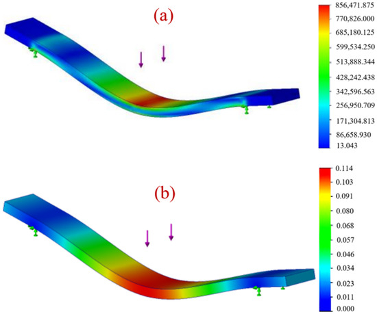
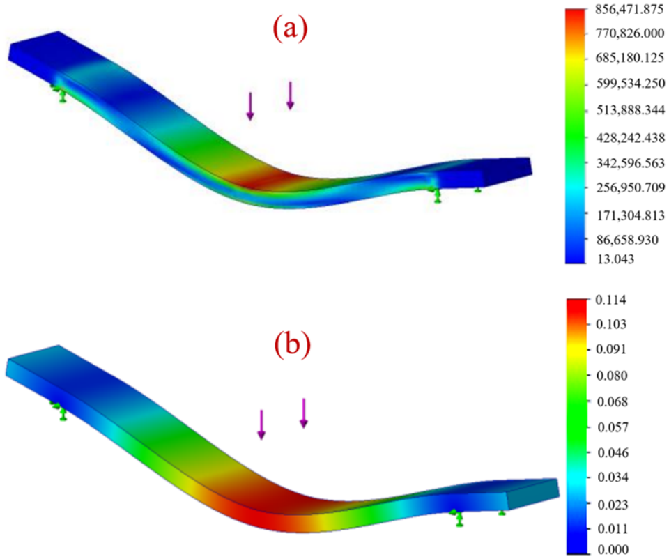
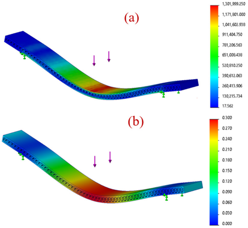
Finite element simulations were performed in accordance with ASTM D790 standards using a three-point bending setup representative of UAV operational loading conditions. A baseline solid specimen was first analyzed for reference, as shown in Figure 12, illustrating the corresponding stress distribution and deflection behavior under the applied load. Performance metrics included von Mises stress, deflection, and factor of safety (FOS). All simulations used the material properties of Onyx with appropriate mesh refinement and fixed boundary conditions at the support points.
Figure 12.
Solid specimen under applied load (purple arrows): (a) stress analysis; (b) deflection.
The results revealed a clear distinction between three-dimensional lattice structures and planar cellular patterns. While BCC and FCC configurations exhibited relatively high stiffness, they produced significant stress concentrations at nodal intersections, which may adversely affect fatigue performance under cyclic loading. In contrast, planar architecture demonstrated more uniform stress distribution and improved bending behavior.
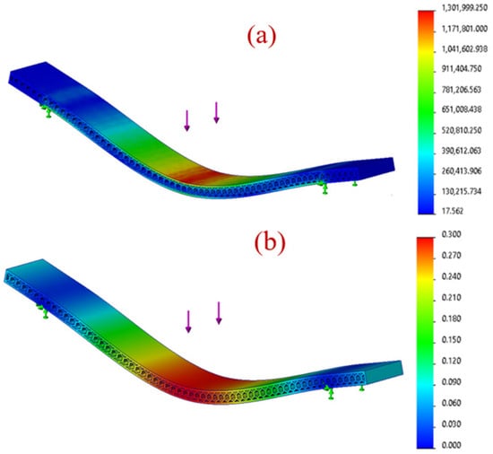
Among all configurations, honeycomb-based patterns provided the most effective balance between strength, stiffness, and weight efficiency. The horizontal honeycomb configuration exhibited the best overall performance under a 1 N applied load, achieving a factor of safety of 4.99, a deflection of 0.0048 m, and a mass reduction of approximately 30–35% compared to the solid baseline (0.00549 kg to 0.00384 kg). The corresponding stress and deformation distributions for this configuration are shown in Figure 13.
Figure 13.
Horizontal honeycomb cellular structure under applied load (purple arrows): (a) stress distribution and (b) deflection under bending load.
Although cellular architecture generally reduces absolute strength relative to solid geometries, they provide substantial weight savings while maintaining sufficient load-bearing capacity for UAV applications. The horizontal honeycomb structure exhibited the lowest peak stress and the most uniform load distribution, indicating superior structural efficiency.
Manufacturability considerations further support this selection. The horizontal honeycomb configuration enables continuous material deposition, minimizes unsupported features, and reduces print time, making it well-suited for reliable additive manufacturing of multi-link assemblies.
Based on the combined criteria of structural performance, weight efficiency, stress distribution, and manufacturability, the horizontal honeycomb pattern was selected as the optimal structural configuration for the robotic arm components.
3.2.3. CAD Model for the UAV Robotic Arm
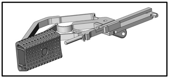
The foldable robotic arm was implemented in a CAD environment based on the Kempe Kite Inversor II linkage, with link-length ratios preserved from the kinematic formulation. The characteristic link length obtained from inverse kinematics () was used to scale the full assembly.
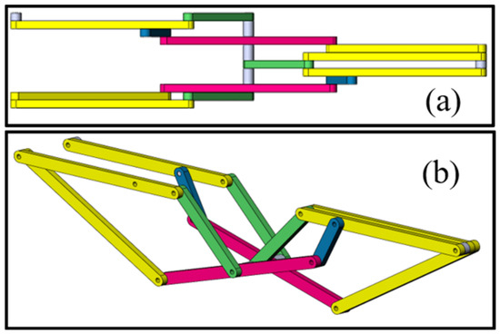
The mechanism was constructed by replicating and arranging individual links according to the kinematic topology. The assembly was mounted to the UAV frame at multiple ground points, and spacers were incorporated to prevent inter-link interference during motion. To ensure symmetric motion and improve structural stability, the linkage configuration was mirrored about its central axis, resulting in a balanced extension–retraction behavior, as shown in Figure 14. The assembly utilized lightweight M3 fasteners with appropriate clearances to accommodate motion and manufacturing tolerances.
Figure 14.
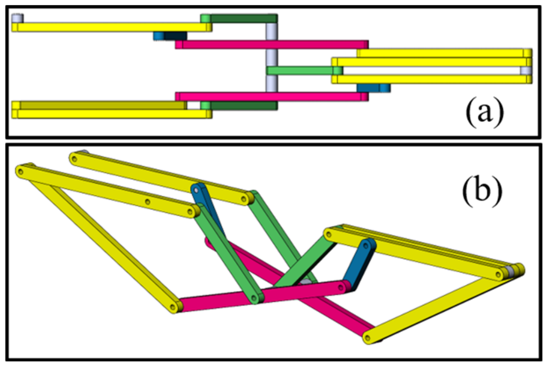
The CAD model of the foldable robotic arm mechanism (a) top view (b) isometric view.
A motion study was conducted to verify kinematic functionality and identify potential interference. A rotational input was applied at the grounded link, and the mechanism was simulated over its operating range. The results confirmed smooth motion, and localized interference near smaller links was mitigated through the introduction of mechanical constraints.
Following kinematic validation, the link geometry was updated to incorporate the selected cellular architecture. The design was constrained by the available UAV mounting space, resulting in an overall assembly width of 0.05537 m and an effective link thickness of approximately 0.0046 m. A clearance of 0.0001 m was introduced between components to account for manufacturing tolerances and reduce friction. Joint interfaces were further refined by incorporating bearing-supported connections, requiring a minimum local thickness of 0.008 m to maintain structural integrity.
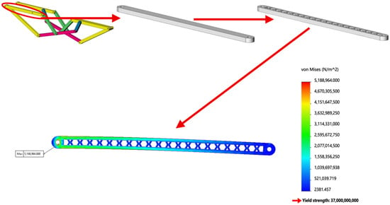
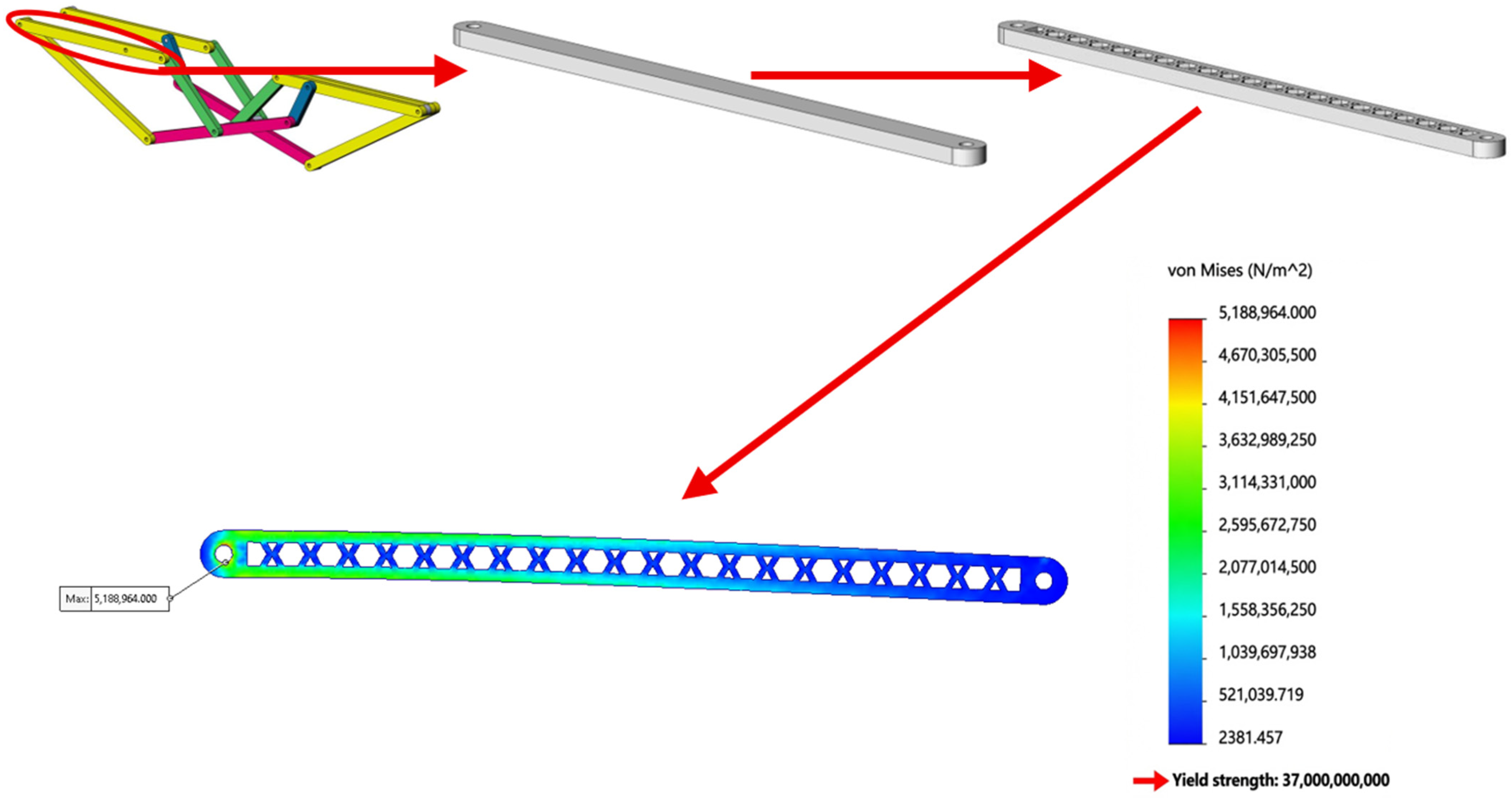
The primary link (denoted as link ) was selected for detailed structural evaluation, as shown in Figure 15.
Figure 15.
Structural redesign of link L, by selecting the solid link from the mechanism and then integrating the cellular architecture; showing the stress analysis of this redesigned link.
Comparative analysis between the solid and optimized cellular configurations under a 1 N load showed that the solid link (mass ) exhibited lower deflection (), while the cellular design reduced mass to with a slightly higher deflection (). The corresponding factors of safety were 4.72 and 4.99, respectively, indicating comparable load-carrying capacity with reduced structural mass.
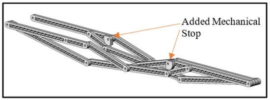
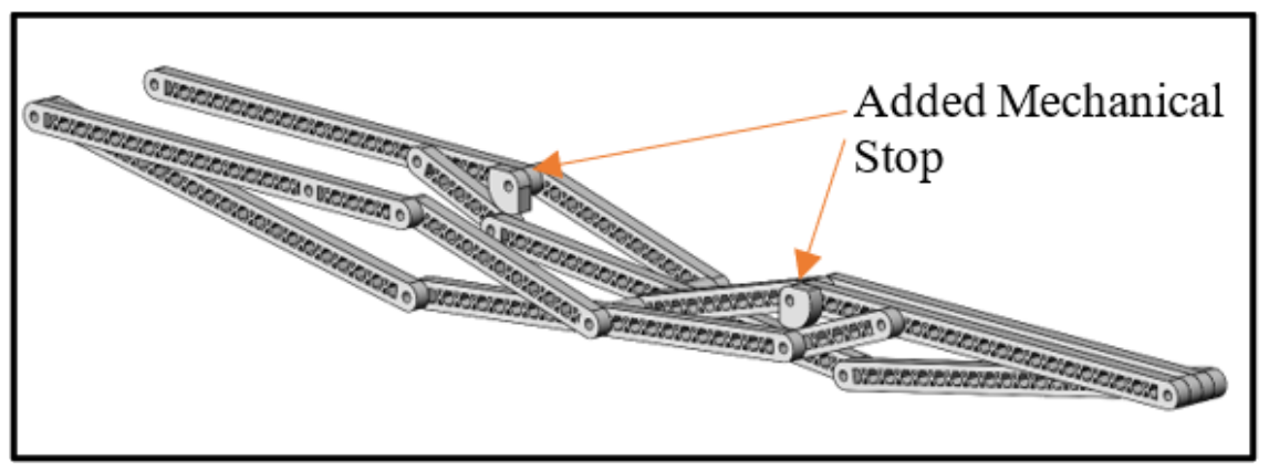
All remaining links were designed using consistent geometric scaling and the selected architecture, with each component verified individually prior to final assembly. Finally, a mechanical stop was incorporated, as shown in Figure 16, to constrain the input motion within the allowable oscillatory range of the mechanism. The system operates as a rocker, with the input angle defined over a finite positive range determined by the linkage geometry. This constraint avoids operation near singular configurations and ensures stable and repeatable motion.
Figure 16.
Assembled and extended configuration of the foldable robotic arm linkage in the CAD environment.
3.3. Compliant Gripper Design
In this system, minimizing actuation requirements is a primary design objective due to the strict payload and energy constraints of UAV platforms. This consideration extends to the grasping mechanism, where conventional motor-driven grippers introduce additional mass, complexity, and power consumption. To address this limitation, a passive or minimally actuated grasping mechanism is required to eliminate the need for dedicated actuators.
Among the available approaches, compliant mechanisms provide an effective solution by achieving motion through elastic deformation rather than rigid-body joints, storing and releasing strain energy within flexible elements [38]. Various design methodologies have been developed, including kinematic synthesis and topology optimization [38]. Recent advances in additive manufacturing have further enabled the realization of compliant mechanisms with complex geometries and tailored mechanical properties, supporting applications in soft robotics and precision devices [39,40]. In robotic manipulation, compliant grippers have demonstrated the ability to passively adapt to object geometry while maintaining reliable grasping performance [41,42,43,44].
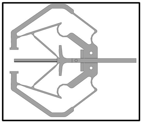
Based on these considerations, a compliant gripper was designed as the end-effector for the proposed robotic arm. The gripper was specifically developed for harvesting small, delicate objects such as cherries, and all geometric and mechanical parameters were selected accordingly to achieve sufficient opening width, high sensitivity to contact, and controlled gripping force to prevent damage. The mechanism operates using a preloaded elastic structure that enables rapid passive closure upon contact, like snap-through compliant systems. A flexible element was incorporated at the fingertips to enhance friction and distribute contact forces. The opening width of the gripper was designed to exceed the characteristic size of the target object, with a nominal opening of 0.050 m. The resulting design is shown in Figure 17.
Figure 17.
Designed compliant gripper.
To improve durability and reduce stress concentration, curved features were incorporated into the compliant structure, enhancing fatigue resistance under repeated loading. The sensitivity of the mechanism was tuned experimentally by adjusting four key geometric parameters that influence stiffness and actuation force, as illustrated in Figure 18. These parameters were varied based on the selected material and additive manufacturing conditions.
Figure 18.
Adjustable geometric parameters for tuning compliant gripper sensitivity.
The gripper operates through a repeatable passive cycle designed for multiple harvesting operations during a single flight. As the arm extends, the compliant gripper remains open until the soft end-effector contacts the target object. Upon contact, the trigger mechanism releases the stored elastic energy, causing the fingers to rapidly close around the object. During arm retraction, a mechanical trigger system automatically resets the gripper and releases the grasped object into the storage net positioned beneath the mechanism. This fully passive operation enables repeated grasping and release cycles during a single flight without requiring additional actuators or manual intervention. The triggering force required to initiate closure was measured to be approximately 0.034 N, indicating high sensitivity and suitability for handling delicate objects.
Experimental evaluation was conducted over 100 operating cycles without failure, demonstrating repeatable and reliable performance. The resulting gripping force was approximately 3.43 N, while the reset force required to reopen the mechanism was approximately 0.34 N. These values were obtained using a precision scale through repeated measurements and averaging. The relationship between trigger force, gripping force, and reset force exhibited consistent proportional behavior, supporting stable operation.
The total mass of the compliant gripper was approximately 0.009 kg. Flexible fingertip elements fabricated from TPU were integrated to improve compliance and frictional contact, each contributing approximately 0.004 kg. A lightweight mounting bracket fabricated from Onyx was designed for integration with the robotic arm, also with a mass of approximately 0.004 kg. The assembled configuration is shown in Figure 19.
Figure 19.
Compliant gripper with flexible fingertip elements and mounting bracket (section view).
Overall, the compliant gripper provides a lightweight, actuator-free solution for grasping delicate objects, enabling passive adaptation, low-force triggering, and reliable operation while satisfying the strict mass and energy constraints of UAV-based manipulation systems.
3.4. Storage System and Landing Gear
3.4.1. Storage System
The integration of an onboard storage system is essential for improving the operational efficiency of UAV-based harvesting. In the absence of local storage, the UAV must repeatedly travel between the harvesting site and a fixed collection point, leading to increased flight time, higher energy consumption, and reduced system productivity. By incorporating a lightweight storage mechanism, the UAV can collect multiple objects during a single flight cycle and deliver them collectively to a designated location. This approach minimizes redundant flight paths and enhances overall mission efficiency, particularly in agricultural applications where multiple items must be harvested sequentially. Despite advances in UAV-based manipulation, integrated storage solutions remain relatively uncommon.
Given the strict payload and aerodynamic constraints, the storage system must be lightweight and minimally resistant to airflow. A net-based storage container was selected due to its low mass and reduced aerodynamic drag compared to solid enclosures, which may behave similarly to a parachute during flight. The net structure allows passive capture of multiple objects while maintaining airflow through the system.
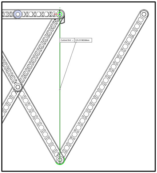
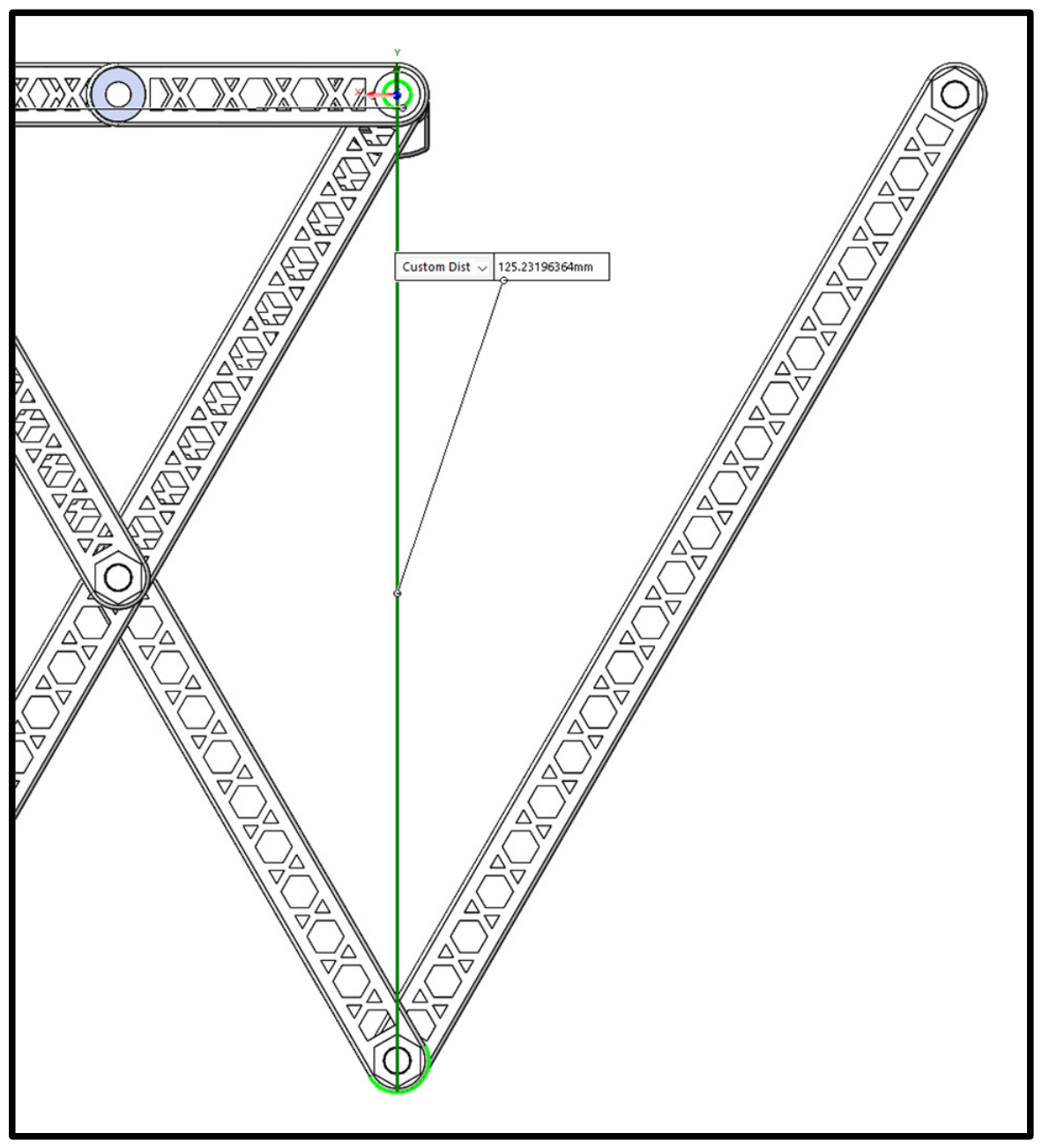
The storage container is positioned directly beneath the robotic arm and gripper to ensure efficient transfer of objects without interfering with the linkage motion. Upon retraction, the compliant gripper is mechanically reset, releasing the fruit into the net container. The fruit experiences a short vertical drop before landing in the soft net. Based on the kinematic configuration of the robotic arm, the maximum distance from the grounded joint to the end-effector is 0.1252 m (drop height of the object). Therefore, a minimum clearance of 0.126 m is required between the ground link and the storage system to ensure unobstructed operation, as illustrated in Figure 20.
Figure 20.
Maximum reach from grounded link to end-effector.
Future design improvements may include the addition of a passive closure mechanism to secure collected objects during flight. One potential approach is to incorporate a folding or rotational feature in the net structure to create an artificial seal after object capture, while maintaining the lightweight characteristics of the system.
3.4.2. Landing Gear Integration
The integration of the storage system necessitates modification of the UAV landing configuration to maintain adequate ground clearance. Specifically, the UAV must be elevated by at least 0.126 m to prevent contact between the storage container and the ground during landing. To satisfy this requirement, a dedicated landing gear system was designed and integrated into the platform.
The landing gear was developed as a modular structure to facilitate additive manufacturing and assembly. It supports both the UAV and the storage system while maintaining the overall center of mass of the platform. To minimize structural weight, a topology optimization study was performed to remove low-stress regions, and a cellular (honeycomb) architecture was incorporated to improve strength-to-weight performance.
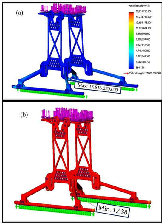
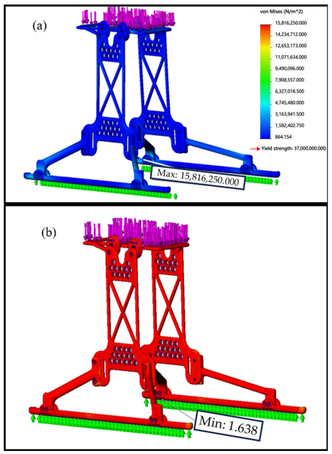
Structural analysis of the optimized landing gear was performed under a total load of 15 N, representing the combined weight of the UAV, storage system, and an additional payload. The resulting factor of safety was 1.6, as shown in Figure 21. Although this value is acceptable, it is relatively close to the lower bound for structural reliability, indicating the need for high-strength materials such as Onyx or equivalent composites.
Figure 21.
Landing gear under load (purple arrows) on ground (green arrows): (a) von Mises stress distribution and (b) factor of safety.
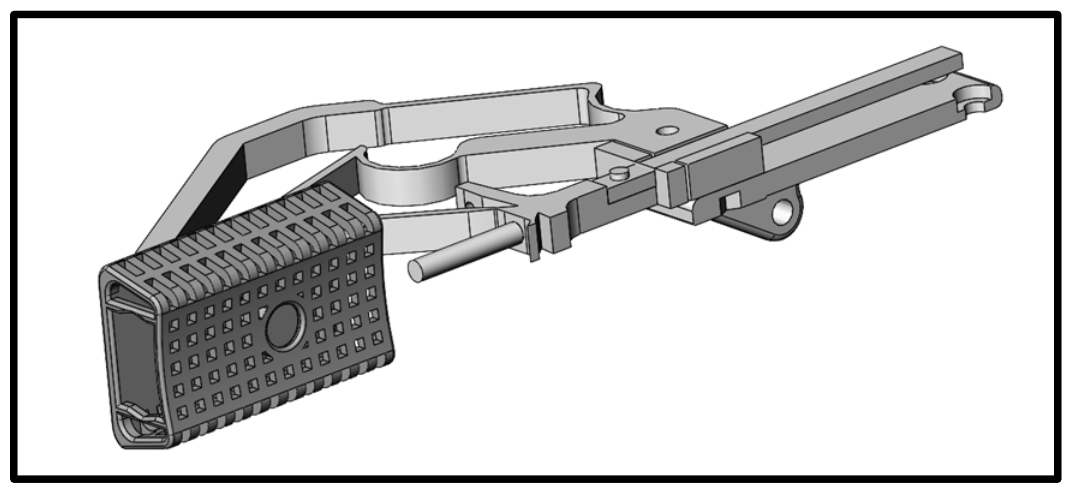
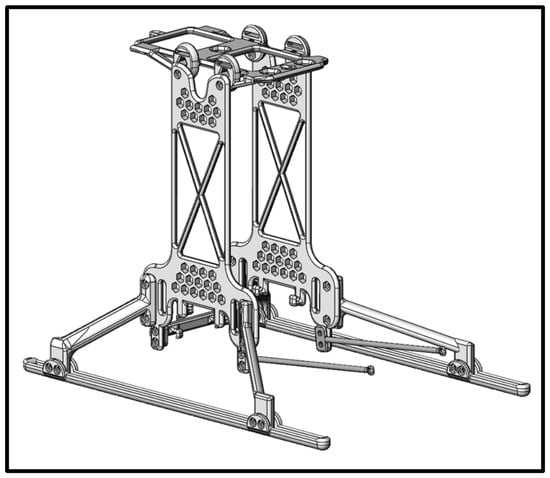
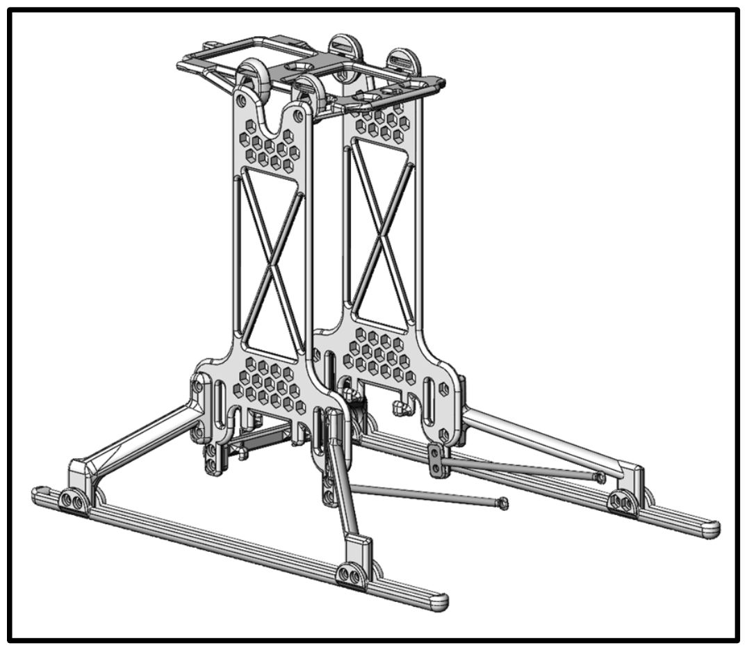
The final landing gear design incorporates angled support members and integrated hooks for attaching the net-based storage container. The complete system, including the storage container and fasteners, has a total mass of approximately 0.12 kg after topology optimization. The assembled configuration is shown in Figure 22.
Figure 22.
CAD model of the landing gear system with integrated storage attachment.
3.5. Actuator Selection and Control System Design
3.5.1. Torque Analysis and Actuator Selection
The actuator selection for the proposed system is governed by the torque required to deploy the foldable robotic arm and simultaneously actuate the counterbalance mechanism. A detailed torque analysis was conducted by considering the mass distribution of the robotic arm, gripper, and payload.
The foldable robotic arm, fabricated using Onyx material (density ≈ 1.2 g/cm3), has a total mass of 0.04906 kg. However, not all components contribute to the torque about the UAV frame. Links that do not extend beyond the drone body, including the ground links (0.004470 kg each) and selected intermediate links (0.001349 kg and 0.004535 kg), were excluded from the torque calculation. The effective mass contributing to the torque was determined to be 0.03424 kg. Including fasteners, joints, and bearings (approximately 0.012 kg total), the effective arm mass increases to 0.04624 kg.
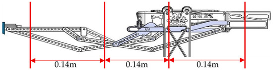
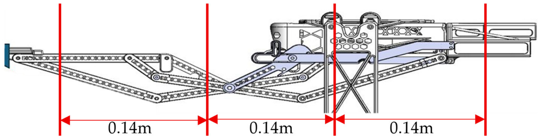
The total extension length of the robotic arm (from retracted to fully extended position) was determined from the CAD model as 0.28 m, where this is the length that is not fixed to the drone. This provides a maximum end-effector reach of 0.42 m from the mounted back joint to the end effector, matching the kinematic analysis and GIM model. A unified dimension diagram of this reach is shown in Figure 23 below.
Figure 23.
Unified dimension diagram.
The maximum available torque from the selected UAV platform is approximately 0.3262 N.m. The addition of a gripper and payload significantly affects the torque requirements. The gripper mass is 0.0315 kg, and the target object (cherry) has an average mass of 0.011 kg. The forces due to gravity are calculated as:
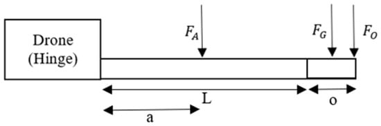
The geometric parameters used in the torque analysis, including the moment arms and force locations, are illustrated in Figure 24.
Figure 24.
Schematic representation of the robotic arm system used for torque analysis, showing force locations and corresponding moment arms.
In this figure:
- a = the distance to the location of the robotic arm’s force;
- L = the total length of the robotic arm;
- o = the distance to where the object is being held by the gripper;
- = Force exerted by the arms’ weight, which is a distributed mass load;
- = Force exerted by the grippers’ weight, which is a distributed mass load;
- = Force exerted by the object weight.
The net torque about the UAV mounting point is expressed as:
Substituting the geometric parameters shown in Figure 23:
The calculated torque is approximately 40% lower than the maximum torque capacity of the UAV (), indicating that the system operates within allowable limits. However, to enhance stability and reduce the moment load on the UAV, particularly under varying flight conditions, a counterbalance mechanism was incorporated.
Using the same torque-balancing approach, the required counterbalance mass was determined to be , positioned approximately behind the UAV center. This configuration offsets the forward torque generated by the robotic arm, effectively reducing the net moment acting on the UAV.
To actuate both the robotic arm and the counterbalance system, a linear actuator was selected.
In addition to the robotic arm torque, the actuator-link geometry introduces an additional torque contribution of approximately . Accordingly, the total motor torque requirement is . The required actuator force was estimated from the torque and stroke length:
Accordingly, a linear actuator with a stroke length of 0.030 m and a load capacity of 30 N was selected to provide an adequate safety margin.
3.5.2. Control System Implementation
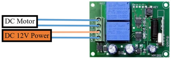
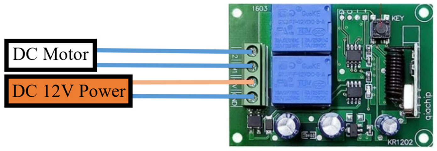
The control system consists of three primary components: a linear actuator (motor), a control module, and a power supply. A 12 V DC linear actuator was selected to drive the mechanism, requiring only bidirectional (forward and reverse) control without the need for speed regulation.
A relay-based control module was used to enable wireless operation. The selected unit operates at up to 28 V DC and 7 A, with a communication range of approximately 50 m. The system is controlled via a pre-configured transmitter, eliminating the need for embedded programming and simplifying implementation.
The control module has a mass of 0.03156 kg and dimensions of 0.074 m × 0.055 m × 0.017 m. Power is supplied using lithium-polymer (Li-Po) batteries. Two 7.4 V, 400 mAh batteries (each weighing 0.016 kg) are connected in series to provide the required 12 V supply.
The combined system is capable of delivering sufficient current (up to approximately 9 A peak) to drive the actuator without instability. Experimental testing confirmed that the actuator can deliver the required force without stalling under load. A simplified block diagram of the control system is shown in Figure 25.
Figure 25.
Control system for the counterbalance and foldable robotic arm.
4. Discussion
Following subsystem-level validation, the fully integrated UAV manipulation system was assembled and evaluated at the system level to assess mass constraints, center-of-mass behavior, actuation performance, and overall functional feasibility.
4.1. System Integration and Mass Evaluation
The complete system was assembled in CAD by integrating the landing gear, robotic arm, gripper, counterbalance, and actuation components within a compact housing. The total mass of the integrated system (excluding the UAV) is 0.318 kg. When accounting for three target objects (total mass ≈ 0.033 kg), the overall system mass increases to 0.351 kg, which remains approximately 16% below the experimentally determined payload capacity of the UAV (0.4185 kg). The UAV payload limit of 0.4185 kg was determined experimentally by incrementally adding known weights until stable hover could no longer be maintained. A detailed mass budget of the integrated system is provided in Table 6. This margin confirms that the system satisfies the primary design constraint of maintaining payload compatibility.
Table 6.
Mass budget of the integrated UAV manipulation system.
4.2. Center of Mass and Stability Behavior
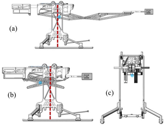
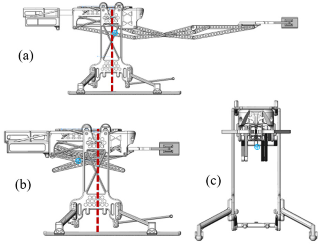
The stability of the system was evaluated through center-of-mass (CoM) analysis in both retracted and extended configurations, as illustrated in Figure 26.
Figure 26.
Center-of-mass distribution (blue dot and red dotted line) in (a) extended, (b) retracted, and (c) front-view configurations.
From the front view, the CoM remains centered, indicating negligible lateral imbalance. Along the longitudinal axis, the CoM shifts depending on the configuration. In the retracted state, the CoM is located approximately 0.039 m behind the UAV reference center due to the counterbalance. In the extended state, this offset reduces to approximately 0.005 m, demonstrating effective compensation of the forward arm extension.
When the UAV mass (0.544 kg) is included, the CoM offset decreases to approximately 0.011 m (retracted) and 0.0012 m (extended), indicating that the combined system remains nearly balanced during operation. This reduced CoM displacement minimizes stabilization effort and contributes to improved flight efficiency.
4.3. Actuation Mechanism Integration
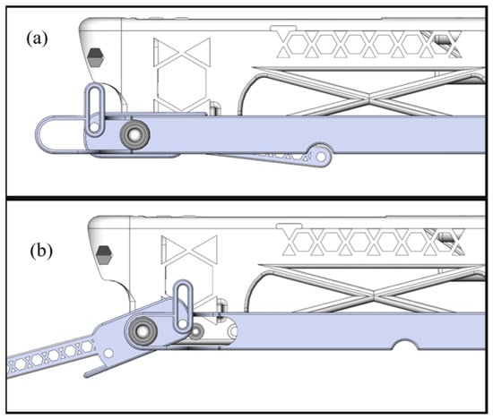
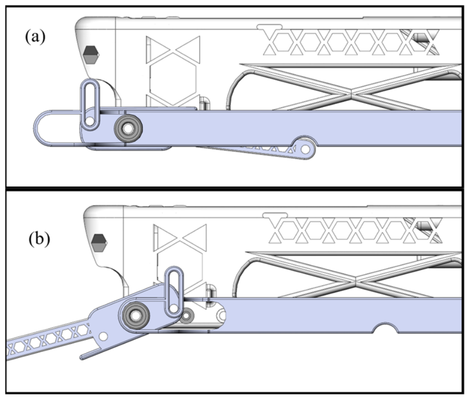
A compact actuation mechanism was implemented to simultaneously drive the robotic arm and counterbalance system. A Scotch Yoke configuration was selected to convert the linear motion of the actuator into rotational motion required by the linkage [45].
The actuator provides a linear stroke of 0.030 m, which is translated into rotational motion over an angular range defined by the actuator-link kinematics. The mechanism geometry was determined to satisfy the required motion while maintaining compactness. The final design incorporates a guide rail to constrain motion and a bearing interface to reduce friction. The integrated mechanism is shown in Figure 27.
Figure 27.
Scotch yoke actuation mechanism in (a) retracted and (b) extended positions.
This configuration enables a single actuator to drive both subsystems without interference, while maintaining mechanical simplicity and reliability.
4.4. Prototype Fabrication and Flight Demonstration
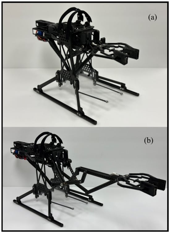
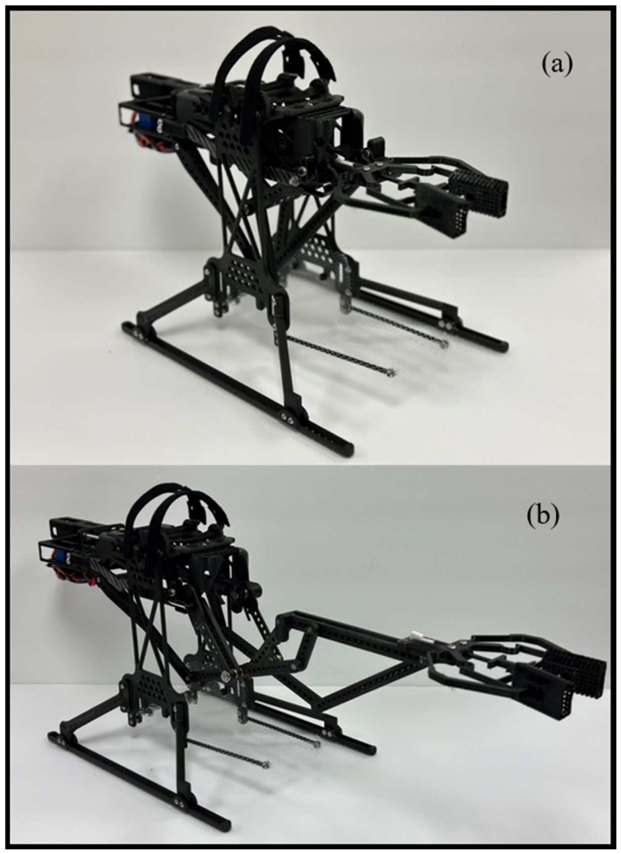
A physical prototype was fabricated and assembled to validate the system design. The assembly process closely followed the CAD model, and all components were integrated without modification. The final prototype is shown in Figure 28.
Figure 28.
Physical prototype of the system: (a) extended and (b) retracted configurations.
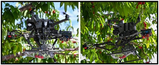
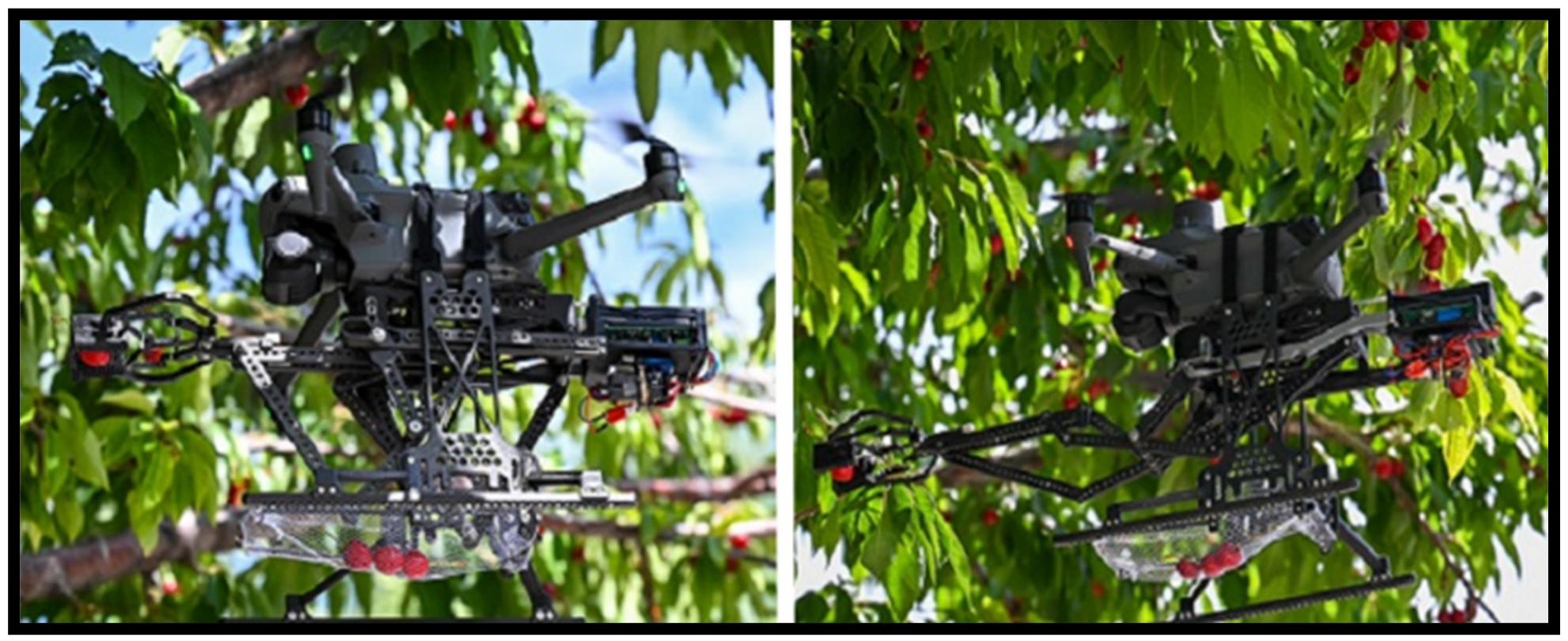
The assembled system demonstrated consistent kinematic behavior and stable actuation across its operating range. Experimental benchtop testing of the physical prototype confirmed that the end-effector follows a near-straight-line trajectory with low vertical deviation (maximum y-deviation < 2 mm). Measured x-displacement and repeatability showed good agreement with both the analytical vector-loop model, CAD model, and GIM simulation results across multiple extension-retraction cycles. These results validate the effectiveness of the Kempe Kite Inversor II mechanism for producing predictable linear motion suitable for UAV applications. Figure 29 illustrates the system in flight, demonstrating successful grasping and collection of cherries under real operating conditions. At this stage, the flight harvesting demonstrations were conducted as proof-of-concept tests to validate the practical integration and performance of the proposed robotic arm; therefore, the flight tests used manual remote-control operation rather than a fully autonomous harvesting strategy. A summary of the proof-of-concept flight demonstrations is presented in Table 7.
Figure 29.
Field demonstration of the UAV-integrated robotic manipulation system performing aerial harvesting of cherries.
Table 7.
Summary of the proof-of-concept flight harvesting tests *.
4.5. Limitations and Practical Considerations
Although the prototype demonstrated successful proof-of-concept harvesting, several practical aspects should be noted. The current compliant gripper primarily grasps the body of the cherry rather than the peduncle (stalk). The compliant gripper generates an average gripping force of approximately 3.43 N. While this force was sufficient to detach many cherries during benchtop and flight tests, it is not always reliable for cherries with firmer stems or larger fruit. However, the end-effector is modular, allowing future integration of a cutting mechanism in the upper portion of the flexible grasping area to sever the stem and reduce pulling force on the branch. Also, due to the rectilinear motion of the Kempe Kite Inversor II arm, effective harvesting from dense clusters would require the UAV to reposition itself for each fruit at maximum extension. Ideally, a supported version of this system is planned for future development to use vision-based distance sensing and autonomous control to handle large groups of cherries or objects, with the modular gripper being adjusted accordingly.
Additionally, detaching cherries from the stem often induces branch recoil and subsequent oscillations that must dampen before the next harvest attempt, increasing cycle time. Traditional manual picking applies a vertical pulling force, whereas the current prototype relies on horizontal rectilinear extension. This difference in detachment dynamics may affect harvesting efficiency in real orchard conditions. Future work will explore combining arm motion with controlled drone movement to better replicate vertical detachment forces.
The vertical drop distance from the gripper to the storage net upon retraction is approximately 0.125 m. Both the net and its supporting structure are highly flexible and effectively absorb impact energy. Although the flexible net structure is designed to absorb impact energy, there remains a risk of bruising if a cherry lands directly on top of previously collected fruit. In testing with an empty net, individual cherries showed no immediate visible damage, except one which did land directly on top of previously collected fruit. The collected cherries naturally roll toward the back of the net, closer to the system center of mass. A typical cherry weighs between 4 and 10 g. For proof-of-concept simplicity and to maintain a safe payload margin on the selected UAV, the current net-based storage system only held approximately 3–6 cherries per flight. This limited capacity was intentionally chosen to demonstrate the core functionality of the system while keeping the total operational mass at 0.351 kg (including payload) which helped mitigate the drop damage from cherry to cherry. The current mechanism and storage system are designed for a small UAV; however, the proposed approach is scalable to larger UAV platforms with higher payload capacities, enabling the transport and storage of a greater number of harvested fruits per flight cycle.
It is important to note that while cherries were used as a representative delicate test object, the compliant gripper design is modular and can be readily adapted for a wide variety of other fruits and objects by modifying the end-effector geometry, grasping force characteristics, and scaling the mechanism. Future work will focus on stem-cutting integration, improved storage mechanisms to further minimize fruit-on-fruit contact, vision-based positioning for harvesting clusters, and exploring combined horizontal-vertical detachment strategies.
5. Conclusions
This work presented the design, kinematic analysis, structural optimization, and development of a lightweight foldable robotic arm based on the ten-bar Kempe Kite Inversor II linkage for UAV-based aerial manipulation. The mechanism was selected for its ability to produce precise straight-line motion using a single actuator, combined with good compactness when retracted. Kinematic modeling, singularity analysis, and structural optimization using additive manufacturing and honeycomb cellular architectures resulted in a low-mass arm suitable for UAV integration. Supporting components such as a passive compliant gripper, counterbalance system, storage net, and landing gear were added to evaluate the arm in a practical harvesting scenario using cherries as the test object.
The complete prototype system has a total mass of 0.351 kg (including payload) and remained within the payload capacity of the selected UAV platform. Proof-of-concept flight tests demonstrated successful grasping and collection of cherries, where these results validate the practical integration and performance of the proposed arm. These results indicate the technical feasibility of using this type of single-actuator straight-line linkage for lightweight aerial manipulation tasks.
Future work will include autonomous vision-based fruit detection, closed-loop control, improved storage mechanisms to reduce fruit damage, stem-cutting integration for better detachment, and larger-scale field validation in actual agricultural environments. Overall, the developed foldable robotic arm provides a promising foundation for further development of UAV-based manipulation systems in precision agriculture.
6. Patents
A non-provisional patent application related to the UAV-integrated robotic manipulation system described in this study has been filed and is currently under review.
Author Contributions
Conceptualization, T.D.; methodology, T.D. and K.C.B.; software, K.C.B.; validation, T.D. and K.C.B.; formal analysis, K.C.B.; investigation, K.C.B.; resources, T.D.; data curation, K.C.B.; writing—original draft preparation, K.C.B.; writing—review and editing, T.D.; visualization, K.C.B.; supervision, T.D.; project administration, T.D. All authors have read and agreed to the published version of the manuscript.
Funding
This research was supported by the Center for Ecological Research and Education (CERE) at Idaho State University.
Institutional Review Board Statement
Not applicable.
Informed Consent Statement
Not applicable.
Data Availability Statement
The data supporting the findings of this study are not publicly available due to intellectual property considerations associated with a pending patent application. Experimental data, CAD files, simulation files, and supporting documentation are securely stored on external storage devices and university computing systems and may be made available from the corresponding author upon reasonable request, subject to intellectual property restrictions.
Acknowledgments
The authors would like to acknowledge the Center for Ecological Research and Education (CERE) at Idaho State University for supporting this research project. The authors also wish to acknowledge Alfonso Hernández, CompMech, Department of Mechanical Engineering, UPVEHU for the permission to use the GIM® software.
Conflicts of Interest
The authors declare no conflicts of interest.
Abbreviations
The following abbreviations are used in this manuscript:
| AGV | Autonomous Ground Vehicle |
| UAV | Unmanned Aerial Vehicle |
| DOF | Degrees of Freedom |
| KGC | Chebychev–Grübler–Kutzbach |
| DH | Denavit–Hartenberg |
| C-Space | Configuration Space |
| AM | Additive Manufacturing |
| BCC | Body-Centered Cubic |
| FCC | Face-Centered Cubic |
| FOS | Factor of Safety |
| CoM | Center of Mass |
References
- Rondelli, V.; Franceschetti, B.; Mengoli, D. A review of current and historical research contributions to the development of ground autonomous vehicles for agriculture. Sustainability 2022, 14, 9221. [Google Scholar] [CrossRef] [Scilit]
- Amanullah, D.; Khalid, S. Agronomy: Climate Change; BoD—Books on Demand: Norderstedt, Germany, 2020; Available online: https://books.google.com/books?id=Ppn8DwAAQBAJ&lpg=PP12&ots=u049n_qY0Y&dq=Khalid%2C%20S.%20Agronomy%3A%20Climate%20Change&lr&pg=PP12#v=onepage&q=Khalid,%20S.%20Agronomy:%20Climate%20Change&f=false (accessed on 25 February 2023).
- Kontogiannis, S.G.; Ekaterinaris, J.A. Design, performance evaluation and optimization of a UAV. Aerosp. Sci. Technol. 2013, 29, 339–350. [Google Scholar] [CrossRef] [Scilit]
- Bazargani, K.; Deemyad, T. Automation’s Impact on Agriculture: Opportunities, Challenges, and Economic Effects. Robotics 2024, 13, 33. [Google Scholar] [CrossRef] [Scilit]
- Ladipo, M.; Bazargani, K.; Bingham, K.C.; Sourani Yancheshmeh, S.; Deemyad, T. Height-Adjustable AGV with Adaptive Suspension for Challenging Terrains. In Proceedings of the ASME 2025 International Design Engineering Technical Conferences and Computers and Information in Engineering Conference, Anaheim, CA, USA, 17–20 August 2025; p. DETC2025-169260. [Google Scholar] [CrossRef] [Scilit]
- Korpela, C.M.; Danko, T.W.; Oh, P.Y. MM-UAV: Mobile manipulating unmanned aerial vehicle. J. Intell. Robot. Syst. 2011, 65, 93–101. [Google Scholar] [CrossRef] [Scilit]
- Caccavale, F.; Giglio, G.; Muscio, G.; Pierri, F. Cooperative impedance control for multiple UAVs with a robotic arm. In Proceedings of the IEEE Conference Publication; IEEE Xplore; IEEE: New York, NY, USA, 2015; Available online: https://ieeexplore.ieee.org/abstract/document/7353697 (accessed on 25 February 2024).
- Tsouros, D.C.; Bibi, S.; Sarigiannidis, P.G. A review on UAV-based applications for precision agriculture. Information 2019, 10, 349. [Google Scholar] [CrossRef] [Scilit]
- Quaglia, G.; Visconte, C.; Scimmi, L.S.; Melchiorre, M.; Cavallone, P.; Pastorelli, S. Robot arm and control architecture integra-tion on a UGV for precision agriculture. Adv. Mech. Mach. Sci. 2019, 73, 2339–2348. [Google Scholar] [CrossRef] [Scilit]
- Kim, J.; Kim, S.; Ju, C.; Son, H.I. Unmanned aerial vehicles in agriculture: A review of perspective of platform, control, and applications. IEEE Access 2019, 7, 105100–105115. [Google Scholar] [CrossRef] [Scilit]
- Parrish, B.E.; McCarthy, J.M.; Eppstein, D. Automated generation of linkage loop equations for planar one degree-of-freedom linkages, demonstrated up to 8-bar. J. Mech. Robot. 2015, 7, 011006. [Google Scholar] [CrossRef] [Scilit]
- Wegrowski, P.; Thomas, W.; Lemrick, J.; Deemyad, T. Advanced folding robotic arm for quadcopters. In Proceedings of the IEEE Conference Publication; IEEE Xplore; IEEE: New York, NY, USA, 2022; Available online: https://ieeexplore.ieee.org/document/9796687/ (accessed on 23 February 2023).
- Thomas, W.; Wegrowski, P.; Lemirick, J.; Deemyad, T. Lightweight foldable robotic arm for drones. In Proceedings of the 2022 Intermountain Engineering, Technology and Computing (IETC); IEEE Xplore; IEEE: New York, NY, USA, 2022; Available online: https://ieeexplore.ieee.org/document/9796899 (accessed on 22 February 2023).
- Lemirick, J.; Thomas, W.; Wegrowski, P.; Deemyad, T. Sarrus linkage aerial drone arm. In Proceedings of the 2022 Intermountain Engineering, Technology and Computing (IETC); IEEE Xplore; IEEE: New York, NY, USA, 2022; Available online: https://ieeexplore.ieee.org/document/9796789 (accessed on 23 February 2023).
- Kim, S.-J.; Lee, D.-Y.; Jung, G.-P.; Cho, K.-J. An origami-inspired, self-locking robotic arm that can be folded flat. Sci. Robot. 2018, 3, eaar2915. [Google Scholar] [CrossRef] [Scilit]
- Kim, D.; Oh, P.Y. Lab automation drones for mobile manipulation in high throughput systems. In Proceedings of the 2018 IEEE International Conference on Consumer Electronics (ICCE); IEEE Xplore; IEEE: New York, NY, USA, 2018; Available online: https://ieeexplore.ieee.org/document/8326268 (accessed on 23 February 2023).
- Fishman, J.; Ubellacker, S.; Hughes, N.; Carlone, L. Dynamic grasping with a “soft” drone: From theory to practice. In Proceedings of the 2021 IEEE/RSJ International Conference on Intelligent Robots and Systems (IROS); IEEE Xplore; IEEE: New York, NY, USA, 2021; Available online: https://ieeexplore.ieee.org/document/9635927 (accessed on 23 February 2023).
- Suthar, B.; Jung, S. Design and feasibility analysis of a foldable robot arm for drones using a twisted string actuator: FRAD-TSA. In IEEE Robotics and Automation Letters; IEEE Xplore; IEEE: New York, NY, USA, 2021; Available online: https://ieeexplore.ieee.org/document/9444212 (accessed on 23 February 2023).
- Ali, Z.A.; Zhangang, H. Maneuvering control of hexrotor UAV equipped with a cable-driven gripper. In IEEE Access; IEEE Xplore; IEEE: New York, NY, USA, 2021; Available online: https://ieeexplore.ieee.org/document/9417166 (accessed on 23 February 2023).
- Ham, A. Drone-based material transfer system in a robotic mobile fulfillment center. In IEEE Transactions on Automation Science and Engineering; IEEE Xplore; IEEE: New York, NY, USA, 2020; Available online: https://ieeexplore.ieee.org/document/8920130 (accessed on 23 February 2023).
- Tscholl, D.; Gravert, S.-D.; Appius, A.X.; Katzschmann, R.K. Flying hydraulically amplified electrostatic gripper system for aerial object manipulation. arXiv 2022, arXiv:2205.13011. Available online: https://arxiv.org/abs/2205.13011 (accessed on 19 June 2024).
- Ramon-Soria, P.; Gomez-Tamm, A.E.; Garcia-Rubiales, F.J.; Arrue, B.C.; Ollero, A. Autonomous landing on pipes using soft gripper for inspection and maintenance in outdoor environments. In Proceedings of the 2019 IEEE/RSJ International Conference on Intelligent Robots and Systems (IROS); IEEE Xplore; IEEE: New York, NY, USA, 2019. [Google Scholar] [CrossRef] [Scilit]
- Meng, J.; Buzzatto, J.; Liu, Y.; Liarokapis, M. On aerial robots with grasping and perching capabilities: A comprehensive review. Front. Robot. AI 2022, 8, 739173. [Google Scholar] [CrossRef] [Scilit]
- Käslin, F.; Baur, T.; Meier, P.; Koller, P.; Buchmann, N.; D’Odorico, P.; Eugster, W. Novel twig sampling method by unmanned aerial vehicle (UAV). Front. For. Glob. Change 2018, 1, 2. [Google Scholar] [CrossRef] [Scilit]
- Zirka, A.; Zirka, M.; Kadet, N. Ensuring speed stability of the unmanned aerial vehicle in different flight modes. Sci. Based Technol. 2023, 58, 2. Available online: http://nbuv.gov.ua/UJRN/Nt_2023_2_3 (accessed on 24 January 2025).
- Velusamy, P.; Rajendran, S.; Mahendran, R.K.; Naseer, S.; Shafiq, M.; Choi, J.-G. Unmanned Aerial Vehicles (UAV) in Precision Agriculture: Applications and Challenges. Energies 2022, 15, 217. [Google Scholar] [CrossRef] [Scilit]
- Win, S.K.H.; Win, L.S.T.; Sufiyan, D.; Foong, S. Design and control of the first foldable single-actuator rotary wing micro aerial vehicle. Bioinspir. Biomim. 2021, 16, 066019. [Google Scholar] [CrossRef] [Scilit]
- Yao, W.; Liu, C.; Liu, Y.; Zheng, Q.; Wang, J.; Yu, H.; Chen, C.; Guo, S. Unmanned aerial vehicle payload technology applications in agriculture and other low-altitude scenarios: A review. Front. Plant Sci. 2025, 16, 1721484. [Google Scholar] [CrossRef] [Scilit] [PubMed]
- Bingham, K.C.; Deemyad, T. Design and kinematic analysis of an aerial robotic arm for precision agriculture. In Proceedings of the 2024 Intermountain Engineering, Technology and Computing (IETC), Logan, UT, USA, 13–14 May 2024; pp. 312–317. [Google Scholar] [CrossRef] [Scilit]
- Petuya, V.; Macho, E.; Altuzarra, O.; Pinto, C.; Hernández, A. Educational software tools for the kinematic analysis of mecha-nisms. Comput. Appl. Eng. Educ. 2011, 22, 72–86. [Google Scholar] [CrossRef] [Scilit]
- Kempe, A.B. How to Draw a Straight Line; a Lecture on Linkages. Internet Archive. 1877. Available online: https://archive.org/details/howtodrawstraigh00kemprich (accessed on 22 February 2023).
- Deemyad, O.; Heidari, O.; Perez-Gracia, A. Singularity design for RRSS mechanisms. In Mechanisms and Machine Science; Springer: Berlin/Heidelberg, Germany, 2020; pp. 287–297. [Google Scholar] [CrossRef] [Scilit]
- Basu, D.; Ghosal, A. Singularity analysis of platform-type multi-loop spatial mechanisms. Mech. Mach. Theory 1997, 32, 375–389. [Google Scholar] [CrossRef] [Scilit]
- Bingham, K.C.; Yancheshmeh, S.S.; Vaidya, G.; Ebrahimpour, A.; Deemyad, T. Advanced material selection and design strate-gies for optimized robotic systems. In Proceedings of the ASME 2024 International Mechanical Engineering Congress and Exposition, Portland, OR, USA, 17–21 November 2024. [Google Scholar] [CrossRef] [Scilit]
- Žmindák, M.; Novak, P.; Soukup, J.; Milosavljevic, D.; Kaco, M. Finite element simulation of tensile test of composite materials manufactured by 3D printing. IOP Conf. Ser. Mater. Sci. Eng. 2020, 776, 012082. [Google Scholar] [CrossRef] [Scilit]
- Truszkiewicz, E.; Thalhamer, A.; Rossegger, M.; Vetter, M.; Meier, G.; Rossegger, E.; Fuchs, P.; Schlögl, S.; Berer, M. Mechanical behavior of 3D-printed polymeric metamaterials for light-weight applications. J. Appl. Polym. Sci. 2022, 139, 51618. [Google Scholar] [CrossRef] [Scilit]
- Chen, Q.; Cao, P.F.; Advincula, R.C. Mechanically robust ultraelastic hierarchical foam with tunable properties via 3D printing. Adv. Funct. Mater. 2018, 28, 1800631. [Google Scholar] [CrossRef] [Scilit]
- Letcher, T.; Waytashek, M. Material property testing of 3D-printed specimens in PLA on an entry-level 3D printer. In Proceedings of the ASME International Mechanical Engineering Congress and Exposition, Montreal, QC, Canada, 14–20 November 2014; p. V02AT02A014. [Google Scholar] [CrossRef] [Scilit]
- Zhu, B.; Zhang, X.; Zhang, H.; Liang, J.; Zang, H.; Li, H.; Wang, R. Design of compliant mechanisms using continuum topology optimization: A review. Comput. Methods Appl. Mech. Eng. 2020, 143, 103622. [Google Scholar] [CrossRef] [Scilit]
- Kumar, P.; Schmidleithner, C.; Larsen, N.B.; Sigmund, O. Topology optimization and 3D printing of large deformation compli-ant mechanisms for straining biological tissues. Struct. Multidiscip. Optim. 2020, 63, 1351–1366. [Google Scholar] [CrossRef] [Scilit]
- Thomas, T.L.; Venkiteswaran, V.K.; Ananthasuresh, G.K.; Misra, S. Surgical applications of compliant mechanisms: A review. J. Mech. Robot. 2021, 13, 021008. [Google Scholar] [CrossRef] [Scilit]
- Liu, C.-H.; Chen, Y.; Yang, S.-Y. Topology optimization and prototype of a multimaterial-like compliant finger by varying the infill density in 3D printing. Soft Robot. 2022, 9, 837–849. [Google Scholar] [CrossRef] [Scilit] [PubMed]
- Mansouri, M.R.; Montazerian, H.; Schmauder, S.; Kadkhodapour, J. 3D-printed multimaterial composites tailored for compli-ancy and strain recovery. Compos. Struct. 2015, 184, 11–17. [Google Scholar] [CrossRef] [Scilit]
- Flores, A.P. Design of A Soft Gripper with Compliant Mechanisms. Bachelor’s Thesis, Tecnológico de Monterrey, Monterrey, Mexico, 2021. Available online: https://repositorio.tec.mx/handle/11285/648441 (accessed on 28 March 2024).
- Adesola, O.K.; Oluwagbemileke, S.A.; Taofik, O.K.; Aderibigbe, A.D.; Olakunle, A.N. An automated Scotch yoke mechanism. Am. J. Biomed. Sci. Eng. 2017, 3, 8–14. Available online: http://www.aascit.org/journal/ajbse (accessed on 20 March 2024).


Disclaimer/Publisher’s Note: The statements, opinions and data contained in all publications are solely those of the individual author(s) and contributor(s) and not of MDPI and/or the editor(s). MDPI and/or the editor(s) disclaim responsibility for any injury to people or property resulting from any ideas, methods, instructions or products referred to in the content. |
© 2026 by the authors. Licensee MDPI, Basel, Switzerland. This article is an open access article distributed under the terms and conditions of the Creative Commons Attribution (CC BY) license.