Abstract
This study addresses the agricultural requirement for flexible adjustment of planting spacing in seed breeding corn, designing an active rotating in-film hole-forming mechanism driven by an independent motor. The mechanism allows flexible regulation of planting spacing by adjusting the motor speed. The study first optimized the structure of the hole-forming device, selecting a rhombic duckbill as its core component and analyzing its motion trajectory and hole-forming shape. Single-factor experiments were conducted to determine the structural parameter ranges affecting film hole length. Using discrete element and multibody dynamics co-simulation, experiments were carried out with duckbill number, duckbill bottom width, and duckbill bottom height as experimental factors, and film hole length as the response variable, employing a three-factor, three-level orthogonal experimental method. Simulation results indicated that the factors influencing film hole length, in descending order of impact, were duckbill number, duckbill bottom height, and duckbill bottom width. The optimized best structural parameters were: 9 duckbills, bottom height of 351 mm, and bottom width of 22 mm, ensuring film hole length control within the range of 25–40 mm, meeting planting requirements, preventing weed growth, and ensuring a seed growth environment. Furrow testing validated the adaptability and planting performance of the mechanism under different spacing conditions, providing a theoretical basis and practical reference for the promotion of small-scale breeding and the sowing technology on the film for field seed production.
1. Introduction
Breeding and seed production are critical components of the maize industry, directly influencing maize yield and supply. In recent years, with the expansion of the maize cultivation area, the maize breeding and seed production sector has experienced rapid development. In northwestern China, including regions such as Inner Mongolia, Gansu, and Xinjiang, although sufficient sunlight is available, water scarcity remains a significant challenge. To address this issue, plastic film mulching sowing technology is commonly employed in maize breeding trials and seed production. This technique involves covering the soil surface with plastic film, which not only reduces water evaporation and maintains soil moisture but also suppresses weed growth, thereby creating favorable conditions for crop development [1,2,3].
However, in these areas, planting densities vary considerably in maize breeding trials. Existing film planters lack the capability for real-time plant spacing adjustment, necessitating reliance on manual sowing operations. Simultaneously, the requirement for staggered sowing of parental lines demands planters with flexible and convenient spacing adjustment functionality to meet diverse sowing needs. Most current film planters utilize passively rotated duckbill-type hole-forming mechanisms with fixed spacing configurations. Adjustment can only be achieved by changing the number of duckbills, which fails to satisfy the requirements for maize breeding trials and dual-purpose sowing of parental lines [4].
Domestic research on film mulching planters originated in the 1980s, primarily categorized into vertical-insertion planters and hole-wheel planters. Chen Xiaoguang pioneered the vertical-insertion hole-forming mechanism in 1993 and developed various hole-forming devices. Wang Zunyuan’s research team designed the first hand-pushed wheel-type punching planter in 1998, achieving precision sowing on plastic film [5]. Subsequent research on film mulching sowing mechanisms has progressively advanced [6,7,8,9,10,11,12]. Existing studies have primarily focused on structural optimization of hole-forming devices, improvement of film penetration performance, and enhancement of sowing uniformity. For instance, Wang Zunji conducted a simulation analysis of hole-forming trajectories using DEM-MBD coupled simulation [13]; Li Yajun performed modeling and simulation of hole-forming wheels through SolidWorks software, investigating the effects of traction speed and slip distance on duckbill trajectories [14]; ZHAO Binqiang employed RecurDyn-EDEM coupled simulation to study the hole-forming mechanism of duckbill-type devices [12]. These investigations have predominantly concentrated on film penetration effectiveness and sowing accuracy, with limited attention to active rotation mechanisms and plant spacing adjustment.
To address these technological limitations, this study proposes an actively rotated film mulching sowing mechanism. By utilizing an electric motor to drive and control the rotational speed of the hole-forming disk, real-time and flexible adjustment of sowing spacing is achieved. This paper first analyzes the motion trajectory and cavity formation characteristics of the hole-forming device; subsequently, through simulation and parameter optimization, the optimal structural parameters are determined to achieve ideal film penetration and sowing quality; finally, soil bin experiments validate the adaptability and sowing performance of the optimized hole-forming device under different spacing conditions.
2. Overall Structure and Working Principle of the Machine
2.1. Overall Structure
The actively rotating hole-forming device adopts a rear-mounted suspension configuration. The unit primarily consists of a frame, seed metering device, seed guiding tube, hole-forming disk, hole-forming duckbill, duckbill opening and closing control mechanism, suspension traction system, pressing wheel, and its adjustment mechanism, among others. Among these, the hole-forming disk and the hole-forming duckbill are the core components. The structure of the unit is shown in Figure 1. Table 1 presents the main parameters of the hole-forming device.
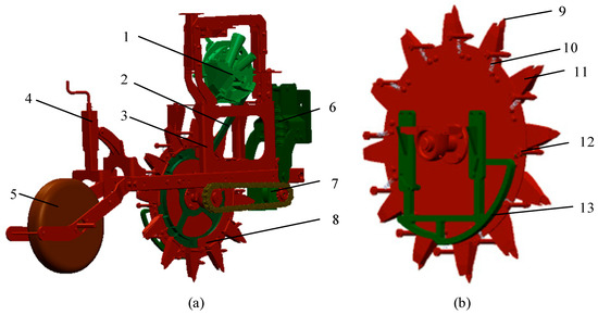
Figure 1.
Schematic of Seeding Unit Assembly. (a) Overall Structure of the Hole-Forming Device; (b) Structural Configuration of the Hole-Forming Disk. 1. Seed Metering Device; 2. Seed Guide Tube; 3. Main Frame; 4. Depth Adjustment Mechanism; 5. Press Wheel; 6. Hitch System; 7. Drive Motor; 8. Seed Drop Mechanism; 9. Retractable Duckbill; 10. Control Spring; 11. Fixed Duckbill; 12. Control Roller; 13. Closing Control Mechanism.

Table 1.
Hole-forming Device Parameters.
2.2. Working Principle
During the seeding operation, the hole-forming device is connected to the tractor via a suspension traction system, allowing the tractor to tow the unit forward and control its forward speed. The hole-forming disk is rotated by a drive motor, which provides rotational power through the hole-forming disk drive shaft, thereby controlling the rotation speed. The rotation of the disk and the forward movement of the machine are independent motions, with no power linkage between them. The hole-forming duckbill rotates with the hole-forming disk. When the duckbill reaches its lowest point, the trajectory of the roller moving on the cam surface that controls the opening and closing of the duckbill changes due to the variation in the shape of the control mechanism surface, causing the duckbill to open. Simultaneously, the seeds within the duckbill fall into the soil due to gravity. As the duckbill continues to rotate with the disk and reaches the designated height above the soil, the roller disengages from the cam surface, and the duckbill closes under the action of spring tension. During the seeding process, the rotational speed of the drive motor can be adjusted to accommodate different planting spacings, thereby enabling real-time and flexible control of the planting spacing.
3. Design and Kinematic Analysis of the Hole-Forming Device
3.1. Design of the Hole-Forming Device
The duckbill-type hole-forming device, as the most commonly used hole-forming mechanism in film mulching seeders, has structural dimensions that directly affect the film-breaking performance of the seeder as well as the shape and size of the formed holes. Common duckbill shapes include wedge-shaped duckbills and conical duckbills.
The soil penetration capability of the duckbill is primarily influenced by soil compaction and the pressure-bearing surface geometry. For calculating soil compaction parameters, given that the hole-forming mechanism typically operates at a depth of 30–50 mm—within the elastic deformation stage of the soil compaction curve—the average soil compaction value of the 0–100 mm soil layer is adopted for computational analysis. The mathematical formulation for soil compaction is expressed as follows:
where, h0 is the probe penetration depth, mm; f(h0)dh0 is the area enclosed by the soil compaction curve and depth threshold h0.
For a given soil type, the variability in soil compaction is limited, allowing it to be approximated as a deterministic value. Consequently, the penetration resistance of the hole-forming mechanism is directly governed by its projected pressure-bearing area. Assuming identical seed inlet diameters at the upper ends of both the wedge-shaped and conical duckbills, along with equivalent maximum hole depths, the projected pressure-bearing area at penetration depth h is calculated as follows:
- wedge-shaped duckbill:
- conical duckbill:
In addition to the aforementioned wedge-shaped and conical duckbills, a third category—prismatic duckbills—exists, with its structural configuration illustrated in Figure 2.
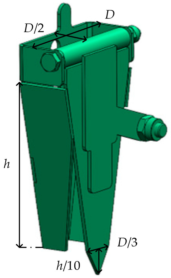
Figure 2.
Schematic of Prismatic Duckbills.
Assuming a prismatic duckbill with a longitudinal width of D and transverse width of D/2 at the seed inlet, and a tip width of D/3 with a tip height of h/10 at the bottom. Given the maximum penetration depth H is identical to that of the aforementioned wedge-shaped and conical duckbills, the projected pressure-bearing area during soil penetration is calculated as follows:
where φ is the included angle between moving and fixed duckbills at closure.
Figure 3 illustrates the variation in the projected pressure-bearing area with penetration depth for three duckbill types. As shown, given identical seed inlet diameters, the pressure-bearing area of all three duckbills increases with greater penetration depth. However, the prismatic duckbill exhibits a significantly smaller pressure-bearing area than the other two types. Consequently, under identical dimensional conditions, the prismatic duckbill generates lower penetration resistance and superior soil penetration capability compared to the wedge-shaped and conical duckbills. Therefore, the prismatic duckbill was selected for this seeding unit.
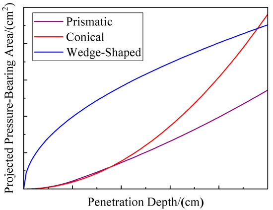
Figure 3.
Variation of Duckbill Positive Pressure Area with Soil Penetration Depth.
3.2. Analysis of Rotational Speed Control
During operation, the hole-forming duckbills rotate about the axis of the hole-forming disk at angular velocity ω along a circular path of radius R, while the entire planter translates at constant speed v. The traction unit provides forward propulsion and a dedicated motor drives the disk’s rotation. The rotational motion of the hole-forming disk and the translational motion of the planter are kinematically independent. Phase synchronization between these motions achieves precise control of intra-row spacing l. To meet sowing requirements at preset spacing l with minimized soil slippage (<5%), the following condition must be satisfied: when the planter’s displacement equals l, the disk’s rotation angle equals the angular interval between adjacent duckbills.
where Z is the number of hole-forming duckbills; v is the planter forward speed, mm/s; l is the preset intra-row spacing, mm; ω is the angular velocity of the hole-forming disk, rad/s; α is the angular interval between adjacent duckbills, rad.
Substituting the disk rotational speed formula (n = 60ω/(2π)) into this constraint yields:
For maize breeding planters, the typical operating speed is approximately 4 km/h (1.11 m/s). Each hole-forming device is equipped with 8–12 duckbills and the adjustable intra-row spacing requirement is 200–250 mm. Substituting these parameters into the kinematic relationship yields a required rotational speed range of 22–42 r/min for the hole-forming mechanism. To achieve this, the drive system is designed using a stepper motor in combination with a reduction gearbox, with the specific components and specifications provided in Table 2.

Table 2.
Motor Drive System.
3.3. Analysis of Cavity Formation Process and Film Hole Length
The motion of the hole-forming device resembles a rolling motion. However, as the hole-forming disk is actively rotated, the linear velocity of points along its rolling radius does not precisely match the planter’s forward speed. A Cartesian coordinate system is established with the disk’s rotation center as the origin (Figure 4).
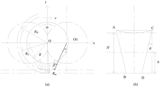
Figure 4.
Seeder Mechanism Action Schematic. (a) Overall Motion Schematic; (b) Duckbill Top Structure Schematic.
During the film-penetrating and soil-engaging process, the formation of seed holes relates to the kinematic characteristic parameter λ of points B and D at the duckbill base. This parameter is defined as the ratio of a point’s linear velocity to the planter’s forward speed, calculated as:
where Rm is the distance from point D to the rotation center O (OD), mm.
The morphology of the hole profile is governed by the motion characteristic parameter λ, and can be categorized into three cases. When λ ≤ 1 (Figure 5a), the profile consists of three segments (ab, bc, and cd). Among them, segment ab is generated by soil compression from the rear surface AB of the duckbill during soil entry, while segment cd is formed by compression of the soil by the front surface CD during soil exit. When 1 < λ < R/Rm (where R denotes the radius of the hole-forming disk, in mm) (Figure 5b), the profile comprises five segments (ae, eb, bd, cf, and fd). Segments ae and cf are produced by compression of the soil from the rear surface AB (entry) and the front surface CD (exit), respectively, whereas segments eb and fd result from shearing action exerted by the rear endpoint B (exit) and the front endpoint C (entry). Finally, when λ ≥ R/Rm (Figure 5c), the profile reduces to two segments (ab and cd). Segment ab is formed by soil shearing due to the rear endpoint B during soil exit, while segment cd is generated by shearing from the front endpoint D during soil entry.
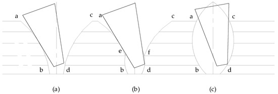
Figure 5.
Hole Contour. (a,b) λ < R/Rm; (c) λ ≥ R/Rm.
When the hole profile corresponds to Figure 5a,b (λ < R/Rm), the film hole length |ac| formed during soil engagement is determined by the motion trajectories of both the duckbill’s rear surface AB and front surface CD. By symmetry in duckbill geometry and motion paths, we analyze only the front surface CD below. The envelope equation of CD’s trajectory is:
where t is the hole formation mechanism motion time, s; θ is the angle between duckbill face CD and the centerline, rad; L is the base width of the duckbill (length BD), mm; RH is the base height of the duckbill (length OO′), mm.
The film hole length formula are:
when the hole profile matches Figure 5c (λ ≥ R/Rm), |ac| is governed by the trajectories of points B and D on the duckbill. Similarly, by symmetry, we consider only point D. Its trajectory is:
where β is the angle between the line connecting the duckbill front end point D and the center O of the rotating disk (OD) and the centerline of the duckbill.
The film hole length formula are:
3.4. Analysis of Soil Disturbance and Backfilling Dynamics Maize
During the soil penetration process, the disturbance induced by the duckbill opener can be divided into lateral and longitudinal components. Both the disturbance velocity and displacement are greater in the lateral direction than in the longitudinal direction, indicating that lateral disturbance constitutes the dominant form of soil disturbance.
Figure 6 shows a cross-section of lateral soil disturbance during the hole-forming process. When the hole-forming device initiates operation, the duckbill is initially closed. Its tip reaches the specified depth following the rotational path of the hole-forming disk. Simultaneously, seeds within the duckbill descend to the top of the bill during soil penetration, as depicted in Figure 6a. At this stage, soil originally occupying the duckbill’s position is laterally displaced by the compressive action of the moving and fixed duckbills. The displaced soil accumulates at its natural angle of repose. Segments ac represent repose boundaries consisting of dry topsoil, while zones be denote moist subsurface soil in direct contact with the duckbill surfaces. Subsequently, the roller controlling the duckbill’s opening/closing moves along the opening segment of the cam profile. The moving duckbill is positively driven open by the force-transmitting linkage connected to the roller, while seeds within the duckbill descend onto the seedbed under gravitational force.
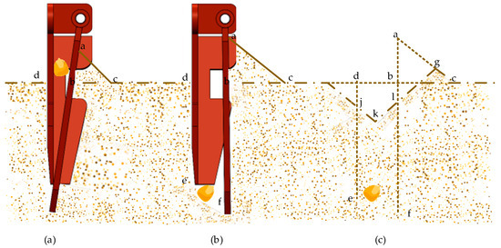
Figure 6.
Soil Disturbance Reflux Process. (a) Duckbill Entry Stage; (b) Duckbill Opening Stage; (c) Duckbill Exit Stage.
Following the duckbill’s retraction from the soil, the laterally displaced soil adjacent to the duckbill walls initiates backflow. This process culminates in the configuration depicted in Figure 6c, where seeds are fully enveloped by moist soil, ensuring optimal germination conditions [15].
The disturbance of soil caused by the duckbill opener is closely related to its entry trajectory, which can be classified into three types according to the kinematic parameter λ, as illustrated in Figure 7. When λ ≤ 1, as shown in Figure 5a, the disturbance is mainly governed by longitudinal compression and local sliding during the entry and exit of the duckbill. In this case, soil particles are primarily compacted in the longitudinal direction, leading to a reduction in porosity. The disturbed zone is confined to the vicinity of the duckbill, with limited soil backflow and the cavity boundaries remaining relatively intact. When 1 < λ < R/Rm, as shown in Figure 5b, soil disturbance is primarily characterized by compression of the upper side of the cavity and shear-induced overturning of the lower side during the entry and exit process. The upper rim of the cavity is uplifted with partial soil backflow, while the lower side is cut and overturned into the cavity, resulting in moist soil at the bottom gradually covering the seeds. When λ > R/Rm, as shown in Figure 5c, the disturbance is dominated by overall shearing and stirring of the soil at the cavity location. In this case, a large volume of soil is displaced and scattered, forming cavities of greater size and extending the disturbance zone to the surrounding soil. The soil skeleton structure is significantly disrupted and the post-disturbance cavity fails to provide a uniform and stable seedbed.
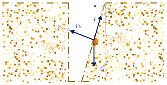
Figure 7.
Analysis diagram of Stressed Soil.
During soil backflow, soil particles are subjected to gravitational force G, normal force FN from the cavity wall, and internal frictional force f. The gravitational force acts vertically downward, the normal force perpendicular to the cavity wall upward, and the frictional force downward along the cavity wall. A local coordinate system is established along the hole wall, as illustrated in Figure 7.
A force analysis of the soil yields the following equations:
where f is the frictional force acting on soil particles, N; G is the gravitational force acting on soil particles, N; θ′ is the inclination angle of moving duckbill relative to vertical plane at full opening, rad; Fy is the net force acting on soil particles along the y-axis, N; μ is the inter-soil frictional coefficient; FN is the normal contact force acting on soil particles, N; m is the soil quality, kg; G is the gravitational acceleration, m/s2.
Since the resultant force acting on the soil clod along the y-axis is zero, it experiences acceleration solely along the x-axis. Consequently, the soil flows back by sliding down along the wall of the planting cavity. The formula for calculating this sliding acceleration is as follows:
The formula for calculating the backflow displacement of soil is as follows:
where ax is the acceleration of soil in the x-direction, m/s2; Sr is the backflow displacement of soil, mm.
3.5. Analysis of Slippage Ratio and Number of Duckbills
When maintaining constant planter speed while adjusting intra-row spacing l via the rotational speed ω of the hole-forming disk, differential slippage occurs between the disk base and the ground. The morphology of soil cavities formed by duckbills is influenced by slippage ratio δ and slippage distance ∆S, calculated as:
where Is is the actual distance traveled per N revolutions of the hole-forming device, mm.
During operation, ω is adjusted to achieve target spacing l, while structural parameter RH (disk radius) and operational speed v remain fixed. Variations in ω alter δ, directly affecting cavity quality. Thus, an optimal δ range must be defined to ensure acceptable hole formation across the required speed range.
Figure 8 depicts the trajectories of duckbill tips under varying δ, with the outermost contour width in each trajectory representing cavity size. When δ > 0.1, the contour width decreases as δ is reduced; however, with further decreases in δ, the width gradually increases. At δ = −0.9, the widened trajectory contour indicates an excessively large cavity, resulting in oversized film holes that do not meet agronomic specifications for precision seeding.
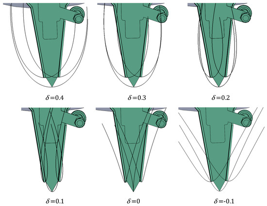
Figure 8.
Duckbill Motion Trajectory of Different Slip Rates.
Field validation confirms that δ ∈ [0, 0.3] ensures optimal film hole dimensions.
When the planter operating speed is held constant, substituting the functional relationship between the rotational speed of the hole-forming disk and the planter forward speed into the slippage ratio formula and rearranging yields:
As derived from the equation, when the structural dimensions of the hole-forming duckbills are fixed, the slippage ratio δ depends on the number of duckbills (Z) and the intra-row spacing (l). Figure 9 plots the variation of δ versus l (200–250 mm) for duckbill quantities Z at a constant operating speed v = 4 km/h (1.11 m/s). The graph demonstrates that: Only the curve for Z = 9 satisfies δ ∈ (0, 0.3) across the entire spacing adjustment range. Thus, configuring nine duckbills on the hole-forming disk ensures optimal film penetration quality when adjusting spacing within specifications.
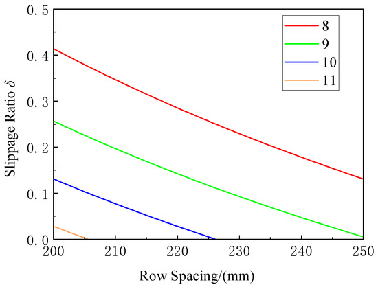
Figure 9.
Relationship between Slip Ratio and Plant Spacing for Different Numbers of Duckbills.
4. Simulation Experiment and Parameter Optimization of the Hole-Forming Device
4.1. Determination of the Experimental Factors
Based on kinematic analysis of the hole-forming device, cavity dimensions are primarily influenced by the planter forward speed (v), disk rotational speed (n), number of duckbills (Z), intra-row spacing (l), rotation radius (Rm) at points B/D, angles between the duckbill faces and the centerline, and the base width (L). Since adjustable spacing (l) is a design objective, it was excluded as an experimental variable, and subsequent tests focused on the remaining factors within the agronomic range of 200–250 mm. Analysis of the slippage ratio indicates a kinematic coupling between v and n in the presence of Z and l; at a fixed v, n becomes deterministic, rendering the slippage ratio (δ) independent of v and the cavity size largely insensitive to changes in forward speed when other parameters are held constant. Under a fixed seed-entry width at the duckbill top, the base height (RH) and base width (L) are interdependent, while the face angles are geometrically constrained. Consequently, the dominant factors controlling film hole length are the number of duckbills (Z), base width (L), and base height (RH).
4.2. Single-Factor Experiment
To determine the factor ranges for optimizing structural parameters of the hole-forming device, single-factor simulation experiments were conducted using the SOLIDWORKS Motion module [16]. The theoretical cavity profile was modeled by simulating the swept area of the soil-engaging duckbill portion, with the maximum longitudinal dimension of the ground-crossing section measured as the theoretical cavity length.
Experimental Setup:
Operating speed: 4 km/h (fixed);
Intra-row spacing: 200 mm, 225 mm, and 250 mm (agronomically validated values);
Tested factors and levels: See Table 3.

Table 3.
Single Factor Test Level.
- (1)
- Effect of duckbill quantity (Z) on film hole length.
Figure 10a–c first line illustrate the film hole profiles generated under varying duckbill quantities at planting spacings of 200 mm, 225 mm, and 250 mm, respectively. When the duckbill quantity (Z) increases while other parameters remain constant, the film hole length exhibits a convex trend, initially decreasing and then increasing across all three spacing conditions. The value of Z corresponding to the minimum film hole length differs with planting spacing: at l = 200 mm, the minimum occurs at Z = 10; at l = 225 mm, at Z = 9; and at l = 250 mm, between Z = 8. These results establish two key relationships: (i) for a fixed planting spacing, the film hole length decreases and then increases with Z; and (ii) the optimal Z value minimizing film hole length shifts upward with increasing planting spacing.
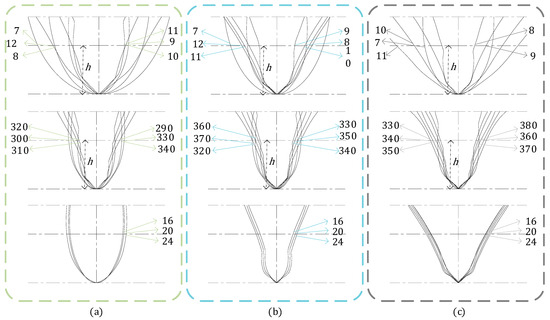
Figure 10.
Cavity Morphology under Different Planting Spacings as Influenced by Various Factors. (a) Hole Shapes Formed Under 200 mm Plant Spacing With Variation of a Single Factor; (b) Hole Shapes Formed Under 225 mm Plant Spacing With Variation of a Single Factor; (c) Hole Shapes Formed Under 250 mm Plant Spacing With Variation of a Single Factor.
- (2)
- Effect of duckbill base height (RH) on film hole length.
Figure 10a–c second line present the film hole profiles formed at different duckbill base heights under planting spacings of 200 mm, 225 mm, and 250 mm, respectively. The analysis shows that at l = 200 mm, the minimum film hole length is obtained when the base height (RH) is 310 mm; at l = 225 mm, the minimum occurs at RH = 340 mm; and at l = 250 mm, the minimum is reached at RH = 360 mm. Accordingly, two general trends are identified: (i) for a fixed planting spacing, film hole length decreases and then increases as RH increases; and (ii) the optimal RH value shifts upward as planting spacing increases.
- (3)
- Effect of duckbill base width (L) on film hole length.
Figure 10a–c third line show the film hole profiles corresponding to different duckbill base widths at planting spacings of 200 mm, 225 mm, and 250 mm. As demonstrated in Figure 10, film hole length increases monotonically with base width (L). Furthermore, for planting spacings of 200 mm and 225 mm, film hole lengths consistently exceed those observed at 250 mm.
4.3. Orthogonal Regression Experiment
- (1)
- Simulation Model Development
The simulation model mainly includes the seeding hole-forming device and the soil simulation model. The experiment requires coupling completed through 3D modeling software, discrete element simulation software, and multi-body dynamics simulation software. First, use SOLIDWORKS2022 to complete the 3D modeling of the hole-forming device, then import it into discrete element software and multi-body dynamics software. The simulation model is shown in Figure 11 [17,18,19,20,21].
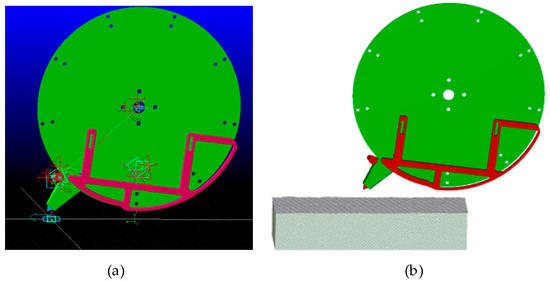
Figure 11.
Seeder Mechanism Simulation Model. (a) ADAMS2019 Simulation Model; (b) EDEM2023 Simulation Model.
In the dynamics software, establish corresponding constraints and kinematic pairs while adding drives to control the mechanism’s motion. In the discrete element software, establish a discrete element model of soil, import the hole-forming device model, and set corresponding contact parameters. Export co-simulation files according to coupling requirements of the discrete element and dynamics software, configure parameters, and finally control the experiment through the simulation interface to obtain test data in the discrete element software. Main simulation parameters are listed in Table 4 [21,22].

Table 4.
Key Simulation Parameters.
When establishing the plastic film simulation model, first build a model using 1 mm diameter particles and simulate. Compare simulation results with actual test effects under identical parameters (Figure 12). Measured film hole length and width are essentially identical. Therefore, considering computer performance, the film simulation model thickness is determined as 1 mm.
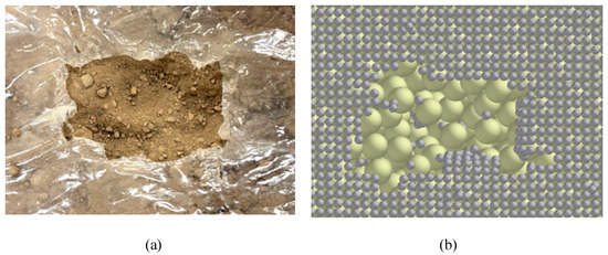
Figure 12.
Comparison of Membrane Breaking Effects. (a) Actual Film Penetration Performance; (b) Simulated Film Penetration Performance.
- (2)
- Experiment design and results.
Based on single-factor experiment analysis, using duckbill quantity Z, duckbill base width L, and duckbill base height RH as experimental factors, with film hole length formed by duckbill soil engagement as the response value. Factor coding is shown in Table 5. Following Box–Behnken experimental design principles, conduct a three-factor three-level orthogonal regression simulation experiment. The experimental plan and results are shown in Table 6, where X1, X2, X3 are coded factor values [23,24].

Table 5.
Orthogonal Experiment Factor Coding.

Table 6.
Experimental Design and Results.
Simulation results (Figure 13) show that when using laterally-opening duckbills, film tearing and lifting are effectively avoided, and film hole dimensions vary under different parameters.
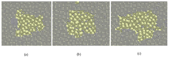
Figure 13.
Membrane Breaking Effects under Different Duckbill Quantities and Base Widths. (a) 9-340-20; (b) 8-340-15; (c) 10-340-25.
Based on the simulation data, the regression model for film hole length Y versus duckbill quantity X1, base height X2, and base width X3 is established as follows.
The variance analysis results are presented in Table 7. The regression model exhibited a highly significant overall effect, with an F-value of 167.08 and p < 0.0001. The lack-of-fit test yielded a p-value of 0.8349 (>0.05), indicating that the model fit was adequate and reliable. The relative influence of the factors and their interactions on film hole length (Y), ranked from strongest to weakest, was as follows: ,
,
X1X2, X1,
, X2, X3,
X1X3,
X2X3. Among these regression terms, six were found to be highly significant (p < 0.01), namely
,
, X1X2, X1,
, and X2; two terms, X3 and X1X3, were significant (p < 0.05); while one term, X2X3, was not significant (p > 0.05).

Table 7.
Analysis of Variance.
- (3)
- Response surface analysis.
The response surface plots of the significant interaction effects on film hole length are presented in Figure 14. The morphology of the response surfaces reflects the intensity of the factor interactions. Figure 14a illustrates the interaction between duckbill quantity (X1) and base height (X2) at a fixed base width of 20 mm. As shown in the figure, when the duckbill quantity is 9 and the base height ranges from 335 to 355 mm, the film hole length reaches its minimum. At a fixed duckbill quantity, an increase in base height initially reduces the film hole length, followed by an increase once the height becomes excessively large. At a fixed base height, the film hole length decreases as the duckbill quantity increases. When both factors simultaneously increase or decrease, the film hole length varies smoothly with limited fluctuation. In contrast, when one factor increases while the other decreases, the film hole length fluctuates drastically. This phenomenon is attributed to the slippage ratio of the hole-forming device. As analyzed in Section 3.5, both excessively high and excessively low slippage ratios result in longer film holes. According to the slippage ratio formula, opposite variations in duckbill quantity and base height induce significant changes in the slippage ratio, while simultaneous increases or decreases in both factors lead to smaller variations.
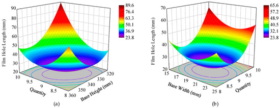
Figure 14.
Effects of duckbill quantity combined with base height and base width on film hole length. (a) Quantity and Base Height; (b) Quantity and Base Width.
Figure 14b shows the interaction between duckbill quantity (X1) and base width (X3) at a fixed base height of 340 mm. The results indicate that the film hole length is minimized when the duckbill quantity is approximately 9 and the base width ranges between 17 and 22 mm. At a fixed duckbill quantity, increasing base width first decreases the film hole length and then increases it once the width becomes excessive. At a fixed base width, the film hole length decreases with increasing duckbill quantity, but when the duckbill quantity becomes too large, the film hole length increases again. These findings demonstrate that both base height and base width interact strongly with duckbill quantity in determining the film hole length, with the effects largely mediated through their influence on the slippage ratio of the hole-forming device.
- (4)
- Parameter optimization process.
To achieve optimal film penetration, Design-Expert was used to optimize parameters based on interaction effect analysis. Excessively large film holes promote weed growth, while overly small holes hinder maize seedling emergence. Thus, the target film hole length was constrained to: 25 mm < Y < 40 mm. The optimization model is:
The optimal parameter values were determined as follows: duckbill quantity of 9.39, base height of 351.07 mm, and base width of 21.73 mm. For practical considerations, the duckbill quantity was rounded to 9, while the base height and base width were adjusted to 351 mm and 22 mm, respectively, to facilitate manufacturing and assembly.
- (5)
- Simulation validation under variable spacing conditions.
These parameters optimize the hole-forming device at 225 mm spacing. To validate feasibility across other spacings, simulations were conducted (Table 8). Results show:

Table 8.
Plant Spacing Verification.
At 200–250 mm spacings, all film hole lengths meet requirements (Y < 40 mm)
Minimum Y = 29.74 mm (at 220 mm spacing);
Maximum Y = 39.18 mm (at 200 mm spacing).
4.4. Verification Translation
To validate the film hole length and seeding performance of the optimized hole-forming device under actual working conditions, soil bin tests were conducted at the National Key Laboratory for Agricultural Equipment. On the test day, the weather was cloudy, with an indoor temperature of 26 °C. Soil conditions in the bin were measured as a moisture content of 14% and a cultivated layer firmness of 260 kPa.
Tests were carried out at planting spacings of 200 mm, 225 mm, and 250 mm. For each spacing group, five repeated tests were performed. The average film hole lengths obtained were 38.79 mm, 26.43 mm, and 39.35 mm, respectively, which were consistent with the simulation results.
The experimental process further demonstrated that the hole-forming mechanism operated stably and reliably; the formed cavities exhibited uniform spacing; and no misalignment occurred between soil cavities and film holes. The test results satisfied all requirements for plastic-film planters. Field test effects are shown in Figure 15.
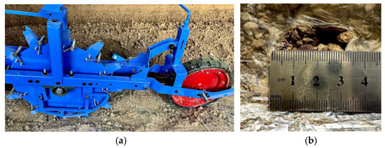
Figure 15.
Field Testing on Soil Trench. (a) Film Penetration Test; (b) Film Hole Length.
5. Discussion
- This study proposes the design of an active rotating hole-forming device tailored for China’s corn breeding and seed production industry. The device employs an in-film hole-forming mechanism using a duckbill-type structure, facilitating the in-film planting of breeding and seed corn. The hole-forming device is independently driven by a motor, with no direct mechanical link to the seeder’s forward speed. Through real-time adjustments to the motor speed, the rotation speed of the hole-forming disc can be controlled, thereby enabling real-time regulation of planting spacing. This design effectively meets the requirements for corn breeding plot sowing and the staged sowing of parent plants in seed corn production. Furthermore, the study delves into the relationship between the number of duckbills and the slip ratio, along with the impact of the geometric parameters of the duckbill. The hole-forming disc is motor-driven, rather than relying solely on rolling over the plastic film surface. A speed differential during soil penetration leads to relative slip, which can affect the film cutting performance. Simulation results indicate that when the slip ratio (δ) is within the range of [0, 0.3], the resulting film hole shape complies with the required specifications. Further analysis reveals that with 9 duckbills, the slip ratio remains within the range [0, 0.3] under the predefined planting spacing and operational speed, thus achieving the desired planting quality. This outcome aligns with the orthogonal experimental results for film hole length. Compared to existing technologies and research, most studies on corn seeders have focused on large-scale field planting, concentrating on issues such as sowing precision and speed. Research concerning planting spacing adjustment and in-film planting is relatively scarce. In transplanting machines, spacing adjustments are generally achieved through mechanical structures, allowing only a limited set of fixed distances, without the capacity for real-time continuous adjustments. In contrast, this study uses a combined dynamic and discrete element method (DEM) simulation to examine the motion trajectory and film-cutting effect of the hole-forming device, providing valuable insights for future research on similar in-film sowing and planting technologies [25,26].
- As the demand for precision management and automation increases in the corn breeding and seed production industries, the potential application of in-film sowing technology becomes increasingly significant. Specifically, in corn breeding, varying plot sizes and planting densities require seeders to adjust planting spacing flexibly to ensure uniform seed development and consistency across breeding plots. In corn seed production, the need for staged sowing of parent plants requires precise control of planting spacing to ensure successful pollination. The proposed active rotating planting mechanism, with its ability to adjust planting accuracy in real-time across varying spacing, ensures uniform seed distribution and effective film cutting during the breeding and seed production processes. This, in turn, improves breeding success rates and seed quality. Mechanized sowing technology not only enhances production efficiency but also reduces labor costs. In particular, in labor-scarce rural areas, automated seeding systems can substitute for significant manual labor, reducing labor costs and improving overall productivity.
- Nevertheless, practical challenges such as production costs, component durability, and potential barriers to implementation remain crucial considerations. First, while the proposed active rotating hole-forming device allows for precise control of planting spacing, the cost of the motor-driven system is relatively high, potentially raising the overall production costs of the seeding machine. Future research should focus on optimizing the motor drive system to minimize unnecessary costs and facilitate large-scale production. Second, the durability of the components in the hole-forming device requires careful consideration. Future work should explore the use of more wear-resistant and corrosion-resistant materials or design more maintenance-friendly and durable components to ensure long-term reliability in harsh operational environments. In addition, the validation experiments were conducted only under a single soil condition, whereas varying soil environments may influence the results. Therefore, subsequent field experiments will be carried out in soils under different environmental conditions. Finally, potential implementation barriers, such as grower acceptance and the challenges of technological promotion in practical agricultural settings, should not be overlooked. These issues will need to be addressed in future research and development efforts.
6. Conclusions
- To address issues like cumbersome spacing adjustment and low precision in existing plastic-film planters, an actively rotated hole-forming device on film was designed. Its structural composition and working principle are elaborated. Precise spacing control is achieved by adjusting the hole-forming device’s rotational speed via an electric motor. Kinematic analysis established motion trajectory equations, identifying duckbill quantity (Z), base width (L), and base height (RH) as primary factors influencing film hole length.
- Using ADAMS-EDEM co-simulation, simulation experiments were conducted. A three-factor three-level orthogonal experiment studied factors affecting film hole size. Results showed the influence hierarchy: Z > RH > L. A quadratic regression model relating film hole length to these factors was developed. Targeting 25–40 mm film holes, optimal parameters were derived:Duckbill quantity: 9;Base height: 351 mm;Base width: 22 mm.
- Soil bin tests at 200 mm, 225 mm, and 250 mm spacings yielded film hole lengths of 38.79 mm, 26.43 mm, and 39.35 mm, respectively, meeting design requirements.
Author Contributions
Conceptualization, C.T. and Z.L.; methodology, C.T. and G.B.; validation, C.T., Z.Z. and J.L.; formal analysis, C.T.; investigation, C.T. and G.B.; resources, C.T. and W.Y.; data curation, C.T.; writing—original draft preparation, C.T., Z.L. and W.Y.; writing—review and editing, C.T., X.C. and W.Y.; visualization, C.T.; supervision, J.L. and X.C.; project administration, W.Y.; funding acquisition, W.Y. All authors have read and agreed to the published version of the manuscript.
Funding
This research was mainly supported by a grant from the project (2023YFD2000402-1) of the National Key R&D Program of China.
Institutional Review Board Statement
Not applicable.
Informed Consent Statement
Not applicable.
Data Availability Statement
Data are reported within the article.
Acknowledgments
The authors would first like to thank the mentor research team for their support. We would also like to thank everyone for their suggestions in the design of the experiment and the theoretical analysis. It is worth mentioning that special thanks to the editorial team and review experts for their help in the content and logic of the article, so that this article can be enriched and perfected and published smoothly.
Conflicts of Interest
Authors Chunshun Tao, Wei Yang, Zhouyi Lv, Guocheng Bao, Zhendong Zhang, Jiandong Li, Xinxin Chen were employed by the company Chinese Academy of Agricultural Mechanization Sciences Group Co., Ltd. The remaining authors declare that the research was conducted in the absence of any commercial or financial relationships that could be construed as a potential conflict of interest.
References
- Zhang, B.C.; Han, H.U.; Guo, Z.Y.; Gong, S.; Shen, S.; Liao, S.H.; Wang, X.; Zhou, S.L.; Zhang, Z.D. Plastic-film-side seeding, as an alternative to traditional film mulching, improves yield stability and income in maize production in semi-arid regions. J. Integr. Agric. 2023, 22, 1021–1034. [Google Scholar] [CrossRef]
- Keane, G.P.; Kelly, J.; Lordan, S.; Kelly, K. Agronomic factors affecting the yield and quality of forage maize in Ireland: Effect of plastic film system and seeding rate. Grass Forage Sci. 2003, 58, 362–371. [Google Scholar] [CrossRef]
- Niu, L.; Yan, Y.Y.; Hou, P.; Bai, W.B.; Zhao, R.L.; Wang, Y.H.; Li, S.K.; Du, T.S.; Zhao, M.; Song, J.Q.; et al. Influence of plastic film mulching and planting density on yield, leaf anatomy, and root characteristics of maize on the Loess Plateau. Crop J. 2020, 8, 548–564. [Google Scholar] [CrossRef]
- Kumar, S.; Singh, S.B. Hybrid seed production technique in maize. In Manual on Training Programme-Cum-Exposure Visit on Advancement in Seed Technology and Marketing; Institute of Agricultural Sciences, BHU: Varanasi, India, 2019; pp. 53–60. [Google Scholar]
- Tao, C.S.; Yang, W.; Li, J.D.; Zhang, Z.D.; Bao, G.C.; Li, H.; Lv, Z.Y. Research status and prospect of seed corn planter. Agric. Eng. 2025, 15, 1–8. [Google Scholar]
- Li, B.; Sun, W.; Zhao, Z.W.; Petru, A.S. Development and Validation of a Potato Seeding Machine with Integrated Plastic Film Mulch Punching Mechanism. Agronomy 2024, 14, 1570. [Google Scholar] [CrossRef]
- Zhou, H.S.; Dai, F.; Shi, R.J.; Zhao, C.; Deng, H.; Pan, H.F.; Zhao, Q.X. Simulation and optimization of a pendulum-lever-type hole-seeding device. Agriculture 2024, 14, 750. [Google Scholar] [CrossRef]
- Xiang, Y.; Kang, J.M.; Zhang, C.Y.; Peng, Q.J.; Zhang, N.N.; Wang, X.Y. Analysis and optimization test of the peanut seeding process with an air-suction roller dibbler. Agriculture 2022, 12, 1942. [Google Scholar] [CrossRef]
- Dai, F.; Guo, W.J.; Song, X.F.; Shi, R.J.; Zhao, W.Y.; Zhang, F.W. Design and field test of crosswise belt type whole plastic-film ridging-mulching corn seeder on double ridges. Int. J. Agric. Biol. Eng. 2019, 12, 101–108. [Google Scholar] [CrossRef]
- Li, H.; Zeng, S.; Luo, X.; Fang, L.Y.; Liang, Z.H.; Yang, W.W. Design, DEM simulation, and field experiments of a novel precision seeder for dry direct-seeded rice with film mulching. Agriculture 2021, 11, 378. [Google Scholar] [CrossRef]
- Pei, L.; Sun, W.; Wang, J.; Pa, S. Design and Experiment of a Film-Drilling Potato Seeder with Eccentric Coupling. Agriculture 2024, 14, 933. [Google Scholar] [CrossRef]
- Zhao, B.Q.; Ni, X.D.; Cai, W.Q.; Li, K.Z. The simulation and parameter optimization of the hole-forming process of a duckbilled hole-forming device. Agriculture 2024, 14, 843. [Google Scholar] [CrossRef]
- Wang, Z.; Zhao, W.Y.; Shi, L.R.; Sun, B.G.; Sun, W.; Dai, F.; Zhou, G.; Guo, J.H.; Rao, G.; Li, H. Optimization of the motion parameters of a rolling spoon type precision hole planter based on DEM-MBD coupling. J. China Agric. Univ. 2024, 29, 66–77. [Google Scholar]
- Li, Y.J.; Shi, L.R. Simulation analysis of picker finger maize dibbler soil penetration trajectory. For. Mach. Woodwork. Equip. 2021, 49, 20–23. [Google Scholar]
- Zhao, S.H.; Tan, H.W.; Wang, J.Y.; Yang, C.; Yang, Y.Q. Design and experiment of multifunctional integrated seeding opener. Trans. Chin. Soc. Agric. Eng. 2018, 34, 58–67. [Google Scholar]
- Gouasmi, M.; Ouali, M.; Fernini, B.; Meghatria, M. Kinematic modelling and simulation of a 2-R robot using solidworks and verification by MATLAB/Simulink. Int. J. Adv. Robot. Syst. 2012, 9, 245. [Google Scholar] [CrossRef]
- Wang, X.; Yang, S.; Li, W.; Wang, Y. Vibratory finishing co-simulation based on ADAMS-EDEM with experimental validation. Int. J. Adv. Manuf. Technol. 2018, 96, 1175–1185. [Google Scholar] [CrossRef]
- Sun, S.; Hu, B.; Wu, X.M.; Luo, X.; Wang, J. Research on a vibrationally tuned directional seed supply method based on ADAMS-EDEM coupling and the optimization of system parameters. Agriculture 2024, 14, 433. [Google Scholar] [CrossRef]
- Guo, J.; Qi, J.; Hu, J.; Hong, C.G.; Shen, Y.L.; Huang, H.Q.; Liu, W.J. Robust optimization method for co-simulation of equipment based on EDEM-ADAMS. Simul. Model. Pract. Theory 2025, 142, 103124. [Google Scholar] [CrossRef]
- Yuan, P.; Li, H.W.; Lu, C.Y.; Wang, Q.J.; He, J.; Huang, S.H.; Cui, D.D. Design and experiment of seed furrow cleaning device based on throwing and sliding for no-till maize seeding. Int. J. Agric. Biol. Eng. 2022, 15, 95–102.21. [Google Scholar] [CrossRef]
- Song, J.L.; Zhang, Y.Z.; Wang, Z.; Li, K.Q.; Cui, Z.C.; Fang, F.H.; Yang, Q.H. Design and Experiment of Asymmetrical Planting Implement for Garlic Upright Planter. Trans. Chin. Soc. Agric. Mach. 2024, 55, 116–128. [Google Scholar]
- Yu, T.; Zhang, Q.; Ju, C.W.; Fan, Y.; Song, J. Calibration of Contact Parameters of Red Peony Root for Transplantation Based on Discrete Element Method. China Agric. Mach. Equip. 2023, 5, 15–20. [Google Scholar]
- Njoku, C.N.; Otisi, S.K. Application of central composite design with design expert v13 in process optimization. In Response Surface Methodology-Research Advances and Applications; IntechOpen: London, UK, 2023; pp. 101–120. [Google Scholar]
- Zhao, X.; Liu, Z.W.; Jia, Y.W.; Ma, X.X.; Zhang, P.F.; Chen, J.N. Optimization design and experiment of the variable differential gear train planting mechanism. Int. J. Agric. Biol. Eng. 2024, 17, 85–93. [Google Scholar] [CrossRef]
- Zhao, X.; Liao, H.W.; Ma, X.X.; Dai, L.; Yu, G.H.; Chen, J.N. Design and experiment of double planet carrier planetary gear flower transplanting mechanism. Int. J. Agric. Biol. Eng. 2021, 14, 55–61. [Google Scholar] [CrossRef]
- Timene, A.; Djalo, H. Design of a five-bar duckbill-type mechanism for sorghum transplanting. J. Agric. Eng. 2023, 54, 29. [Google Scholar] [CrossRef]
Disclaimer/Publisher’s Note: The statements, opinions and data contained in all publications are solely those of the individual author(s) and contributor(s) and not of MDPI and/or the editor(s). MDPI and/or the editor(s) disclaim responsibility for any injury to people or property resulting from any ideas, methods, instructions or products referred to in the content. |
© 2025 by the authors. Licensee MDPI, Basel, Switzerland. This article is an open access article distributed under the terms and conditions of the Creative Commons Attribution (CC BY) license (https://creativecommons.org/licenses/by/4.0/).