Abstract
Soil treatment is one of the most energy-intensive agricultural processes. While power take-off (PTO)-powered rotary tillage tools are widely used due to their operational advantages, their energy efficiency requires enhancement. A new PTO-powered rotary tillage tool was designed, with cutting blades inclined at angle β to prevent soil mass accumulation due to soil sliding along the blades, thereby enhancing energy efficiency and tillage quality. A kinematic model was developed to analyze the tool’s motion trajectories. Theoretical analysis substantiated the optimal inclination angle β = 38–42° and elliptical-profile edge configuration of the cutting blades. During field experiments for performance evaluation, the angle of attack was in the range 20° < α < 40°, and the kinematic coefficient varied in the range 1.0 < η < 1.21 in 0.07 increments. Results demonstrated that draught force and torque reduced by 1.3–1.5 and 1.1–1.4 times, respectively, with an increasing kinematic coefficient. Minimal specific total power requirements of 4.5–4.7 kW/m were obtained at the optimal kinematic coefficient, η = 1.14–1.21, and angle of attack, α = 40°. Compared to base ring tillage discs, the new design reduces total power requirements by 14–16%. Furthermore, it provides required tillage quality: soil pulverization ≥ 80%, weed cutting ≥ 97%, crop residue retention ≥ 60%, and roughness of the field soil surface ≤ 3 cm.
1. Introduction
Soil treatment is one of the most energy-intensive agricultural processes. For performing it, along with sweep tillage tools, free-rolling tillage concave discs set an angle of attack are widely used. These discs basically feature a circular cutting blade edge configuration with different diameters [1,2,3,4]. However, tractors with these implements operate in drawbar mode, and engine power is transmitted to the tillage tools through the soil–tyre interface. It has been reported that only 50–60% of the available engine power is utilized to perform effective field work, while the remaining 40–50% is lost through high wheel slippage at the soil–tyre interface. This inefficient power transmission has low energy efficiency [5,6].
Agricultural implements with PTO-powered tillage tools have drawn considerable research attention in recent years. The main advantage of these tools is their reduction in tractor wheel slippage, as they receive 80–85% of tractor engine power for soil treatment [7,8,9]. This approach not only minimizes negative impacts on soil and improves soil cutting and pulverization but also extends the range of soil moisture conditions under which required work quality can be achieved. Additionally, they exhibit reduced draught requirements. Consequently, these tools enhance both energy efficiency and tillage quality.
PTO-powered tillage discs have become a subject of scientific investigation and field application in modern agricultural system worldwide. Numerous experimental studies have examined PTO-powered tillage disc performance versus free-rolling discs.
Nalavade et al. conducted comparative laboratory experimental studies of free-rolling and power-driven tillage discs, focusing on power requirements and tillage quality [1,7]. It was revealed that the main advantage of power-driven tillage discs over freely rotating ones is the significant reduction in draught force. At angles of attack of 23°, 28°, and 33°, the draught force decreased from 620–947 N to 188–360 N. While power-driven mode showed increased torque requirements, the total energy requirements rose by only 30% compared to those of passive tillage discs. This research also revealed that during the motion of free-rolling discs, soil accumulated in front of disc and creates compressive force on next soil. Consequently, free-rolling discs were found unable to displace the soil smoothly, while forced rotation restricted accumulation in front of the discs. The findings of Nalavade et al. regarding soil accumulation were confirmed by experimental results of Amantayev et al. [10]. They also conducted experiments in soil bin conditions to study soil–free-rolling tillage disc interactions. Their observations revealed that fixed soil bodies accumulated on the tillage disc interface during operation. Based on these findings, they proposed that the energy efficiency and tillage quality performance of tillage discs depend more on the generated soil body parameters than on the tools’ design parameters.
Hann and Giessibl studied the effect of kinematic modes on the energy performance of a single tillage disc [11]. Their research demonstrated a significant reduction in specific draught force when transitioning from free-rolling to powered rotation at a kinematic coefficient of 3.0. Their study identified the optimal efficiency range at kinematic coefficients of 1.0–1.2, with total power requirements approximately doubling when increasing the coefficient to 2.0.
Upadhyay and Raheman developed an active–passive combined offset disc harrow [12,13,14]. Its tillage performance was analyzed through field experiments at different operational settings and compared with that of free-rolling discs. Their results showed optimum tillage performance at kinematic coefficients between 3.0 and 4.0, achieving a 47.8% reduction in draught requirements compared to free-rolling discs. However, the PTO required for operating the tillage discs increased with increasing kinematic coefficients. The results concerning tillage quality indicated better soil pulverization, stubble cutting, and soil inversion efficiency compared to those of free-rolling discs.
Kumar and Singh carried out experiments to study the effect of varying forward speed and angle of attack on the power, energy, and torque of a powered disc [15,16,17,18]. It was observed that angle of attack and forward speed had significant effect on power, energy, and torque requirements. A minimum of 2.29 kW of power was required by a powered disc at an angle of attack of 30° operating at 2 km·h−1 forward speed. Total power requirements increased with increasing forward speed. At a forward speed of 4 km·h−1, the minimum energy requirement was 10.69 Wh. The average increases in torque requirements were 21.62% and 68.46% at forward speeds of 3 and 4 km·h−1, respectively, compared to those at 2 km·h−1.
Beyond the power transmission mode, the design of the cutting blade itself is a critical factor determining energy efficiency and soil tillage quality. Conventional tillage tools, including both free-rolling and PTO-powered discs, predominantly feature cutting blades with a circular edge profile. While simple to manufacture, this design promotes soil mass accumulation and soil body formation in front of the tool, leading to increased draught force and power consumption, as mentioned above.
Recent research has explored blade geometry modifications to mitigate these issues. Nalavade et al. have investigated tillage discs with standard, spiral, and spiral–notched cutting blades [19]. They revealed that the disc with the spiral–notched cutting blade exhibited lower values of soil reactions than those with notched and standard cutting blades. Moreover, it provided smoother operation.
Wells et al. presented fundamental design considerations for powered rotary tillage blades [20]. Their experiments revealed that, in order to minimize power requirements, the ratio of the tangential velocity of cutting edges on a blade divided by the ground speed should be as low as possible as long as a proper tillage action is obtained.
Furthermore, the critical role of blade designs is evident in tillers equipped with rotary tillage tools, which have a horizontal axis and are also widely used in agriculture. These tools are typically installed without an angle of attack, and the blades are the main part interacting with the soil. However, their high operational rotational speed leads to a significant increase in energy requirements. Zhang et al. investigated soil–tool interaction mechanisms and optimized rotary blade design for energy saving in soil cutting [21]. The optimized power consumption was reduced by 9.52% compared to the initial power consumption, validating the effectiveness of energy saving. Yang et al. conducted field experimental studies on optimal designs of cutting blades of bent C, straight, and hoe types of rotary strip-till tools to reduce torque and improve tillage quality [22]. Matin et al. also investigated C-type rotary blade designs and settings to understand the processes of soil cutting, throwing, backfilling, and creation of furrow seedbeds to optimize rotary strip–till systems [23]. Zhang et al. simulated the soil cutting process using a rotary tillage blade and optimized power consumption [24]. Chertkiattipol and Niyamapa studied the torque characteristics and the specific tilling energies of a Japanese C-shaped blade, a European C-shape blade, and a European L-shape blade in rotary tillage tools for seedbed preparation [25]. Results of their experiments show that the shape of the rotary blades influenced their torque characteristic. Due to this, the soil wedge adherence occurred on the surface of the blades. The specific tilling energies of all blades increased with the rotational speed.
Analysis of the literature review reveals the following:
- -
- Numerous experimental studies demonstrate substantial draught force reduction in PTO-powered discs compared to free-rolling discs, though with significantly increased total power requirements;
- -
- Most research has predominantly focused on high-rotational-speed operations, where specific torque and total power requirements rise with increasing kinematic mode;
- -
- While available data confirms the operational advantages of PTO-powered tillage tools, most studies rely on experimental methods, resulting in significant outcome variability due to differing test conditions;
- -
- Although slow rotational speeds with low kinematic coefficients may reduce total power requirements, soil mass accumulation occurs on the tillage disc interface;
- -
- Despite the critical role of cutting blade geometry in rotary tillage tools and the existence of various designs, the elliptical-profile cutting blade has drawn little research attention for PTO-powered applications;
- -
- Existing theoretical analyses offer limited insight into soil–powered tillage disc interaction under low kinematic coefficients and conditions requiring controlled soil sliding, where cutting blade configuration and inclination critically influence energy efficiency.
The purpose of this research is to design a kinematically optimized PTO-powered rotary tillage tool with elliptical cutting blades and to evaluate its performance in terms of energy efficiency and tillage quality.
The novelty of this research lies in the design of an innovative PTO-powered rotary tillage tool that (1) features elliptical-profile cutting blades inclined at an angle β relative to the vector of absolute velocity and (2) operates at low kinematic coefficients of 1.0–1.2.
The originality of this design is its capacity to prevent soil mass accumulation at the soil–tool interface at low kinematic coefficients of 1.0–1.2, thereby enhancing both energy efficiency and tillage quality performance.
Consequently, the main objectives of this research were (1) to develop kinematic modelling and analyze motion trajectories of the rotary tillage tool, (2) to optimize the inclination angle and edge configuration of the cutting blade of the designed rotary tillage tool, and (3) to conduct field experiments to evaluate the energy efficiency and tillage quality performance of the designed rotary tillage tools.
2. Materials and Methods
2.1. Design and Parameters of the Base and Designed Rotary Tillage Tools
A new PTO-powered rotary tillage tool with individual elliptical cutting blades for surface soil treatment was designed based on the base ring disc tillage tool with a circular cutting blade (Figure 1).
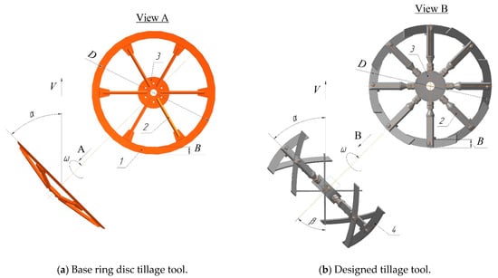
Figure 1.
Rotary tillage tools. 1—circular cutting blade; 2—spoke; 3—hub; 4—elliptical cutting blade.
The base tillage tool consists of a ring rim (1) with a circular cutting blade fixed on spokes (2) connecting the rim to a central hub (3), where a bearing allows it to rotate at an angular velocity, ω, around its axis (Figure 1a). The tillage tool is mounted at an angle of attack, α, relative to the travel direction and moves with translational velocity, V.
The new PTO-powered rotary tillage tool comprises a base hub (3) with multiple cutting blades (4) mounted via spokes (3) (Figure 1b). These blades serve as the operating elements and feature an elliptical cutting-edge profile for improved soil interaction. The tillage tool is oriented at an angle of attack, α, relative to the forward travel direction and moves with translational velocity, V, while simultaneously rotating around its axis at a low angular velocity, ω. Each blade (4) of the designed tillage tool is inclined at an angle, β, relative to the vector of absolute velocity, Va, during penetration into the soil. This design configuration ensures smooth soil sliding along the cutting blades, preventing soil mass accumulation and fixed body formation.
The tillage tools have the following design parameters and operational modes: the outer diameter D is 450 mm, the blade height B is 30 mm, the angle of attack is in the range 20° < α < 40°, and the kinematic coefficient is in the range 1.0 < η < 1.2.
The soil treatment process occurs as follows. The PTO-powered rotary tillage tools, assembled in a gang set at an angle of attack, α, move in the soil at a given forward travel speed and a required tilling depth of up to 8 cm. During operation, each cutting blade sequentially engages the soil, thereby performing the surface soil treatment process.
Figure 2 shows a flow chart of this study of the designed tillage tool.
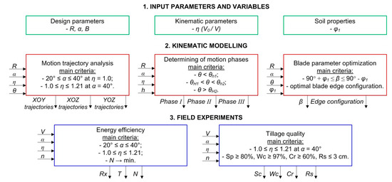
Figure 2.
Research flow chart.
The initial stage of this research is represented by kinematic modelling with motion trajectory analysis. Then the phases of operation of the tillage tool are considered. After that, the parameters of the cutting blade are substantiated. The final results of the research are an evaluation of the energy efficiency and tillage quality of tillage tools in the field.
2.2. Kinematic Model
A rectangular coordinate system, OXYZ, is used for kinematic analysis of the rotary tillage tool–soil interaction (Figure 3).
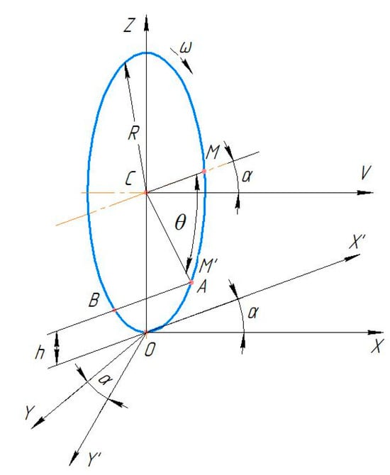
Figure 3.
Schematic view of the movement of the rotary tillage tool.
The origin coincides with the bottom point O of the tillage tool at the furrow bottom. OX represents the forward travel direction V of the tillage tool. OZ is the vertical direction and passes through the bottom contact point O of the tillage tool with the furrow bottom. OY is the transverse direction. The rotation plane of the tillage tool is inclined from the forward travel direction at an angle of attack, α. The auxiliary coordinate system OX’Y’Z’ is created by rotating the main system OXYZ through an angle, α, with respect to the axis OZ.
The curvilinear trajectory formed during the movement of point M on the cutting blade edge of the tillage tool can be described by the following system of equations:
where X, Y, and Z—the coordinates of point M on the cutting blade edge of the rotary tillage tool in the coordinate system OXYZ; R—the radius of the rotary tillage tool, m; θ—the rotation angle of the tillage tool, rad; η—the kinematic coefficient; α—the angle of attack, °.
The kinematic coefficient η characterizes the ratio of the rotational speed V0 to the forward travel speed V of the rotary tillage tool:
where V0—rotational speed, m/s; V—forward travel speed, m/s.
The following operating modes can be defined depending on the value of η: η < 1, motion with slipping (free-rolling, unpowered mode); η = 1, motion without slipping and skidding (powered mode); η > 1, motion with skidding (powered mode).
2.3. Field Experiments
2.3.1. Design Description
Field experimental studies were conducted to evaluate the effects of the kinematic coefficient η and angle of attack α on the energy efficiency and tillage quality performance of the designed PTO-powered rotary tillage tools with elliptical cutting blades. For doing so, a mobile dynamometer rig was developed at the Kostanay branch of the “Scientific and Production Center of Agricultural Engineering” Limited Liability Partnership (LLP) (Kazakhstan), as shown in Figure 4.
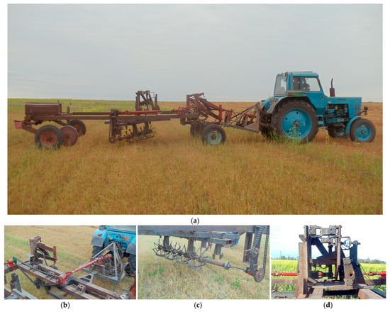
Figure 4.
Mobile dynamometer rig with Belarus-80 tractor: (a)—general view; (b)—torque measuring unit; (c)—rotary tillage tool unit; (d)—tensometric unit.
The mobile dynamometer rig consists of a trailer with four support and transport wheels and a drawbar, which is pulled by a Belarus-80 tractor. Figure 5 presents the kinematic scheme of the mobile dynamometer rig. During operation, the torque from tractor’s PTO to the rotary tillage tools with different rotational speeds is transmitted by means of a drive mechanism with a torque measuring unit. It is located directly behind the tractor’s PTO shank and consists of a gang of rotary tillage tools (1), cardan drive (2), overrun clutch drive (3), overload clutch drive (4), sprocket (5), chain drive (6); support (7), angle gearbox (8), and torque measuring unit (9).
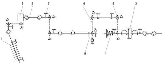
Figure 5.
Kinematic scheme of mobile dynamometer rig: 1—gang of rotary tillage tools; 2—cardan drive; 3—overrun clutch drive; 4—overload clutch drive; 5—sprocket; 6—chain drive; 7—support; 8—angle gearbox; 9—torque measuring unit.
2.3.2. Force Measurement Units
The energy efficiency of the designed PTO-powered rotary tillage tools with elliptical cutting blades was evaluated in terms of specific draught force, torque, and total power requirements. For doing so, a tensometric unit was mounted on the trailer’s frame to measure the draught force acting on the gang of rotary tillage tools during the soil treatment process (Figure 4c). The tensometric unit is a parallelogram mechanism oriented in the forward travel direction, with a strain gauge sensor (1) as its measuring element (Figure 6). The gang of rotary tillage tools (2) is connected to the tensometric unit.
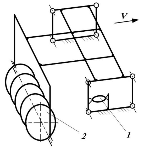
Figure 6.
Scheme of the tensometric unit for draught force measurement of rotary tillage tools: 1—strain gauge sensor; 2—gang of rotary tillage tools.
The torque required for driving the rotary tillage tools was determined using a torque measuring unit located directly behind the tractor’s PTO shaft (Figure 4a). The draught force RX and torque M were measured during the forward travel of the mobile dynamometer rig with the tensometric unit in the operating position in the field. Output signals from the Tenso-M strain gauge sensors were transferred to the electronic Dynamometer Universal (DYN-1U) (Figure 7).
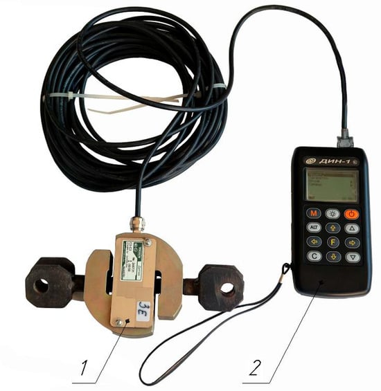
Figure 7.
Strain gage instrumentation for force measurements: 1—Tenso-M strain gauge sensor; 2—electronic Dynamometer Universal (DYN-1U) (complied by Amantayev M.).
All instrumentation was installed in the cab of the Belarus-80 tractor. Each test run was replicated four times—twice in one travel direction and twice in the opposite direction. The obtained data were processed using mathematical statistics.
2.3.3. Test Conditions
Field experiments were conducted in the Kostanay region of Kazakhstan under the following soil conditions: The soil type was southern chernozem with medium loam texture. The soil moisture content was 10.1% in the 0–5 cm layer, 19.4% in the 5–10 cm layer, and 20.7% in the 10–15 layer, and the soil con index was 0.4, 1.5, and 2.9 MPa, respectively. During the tests, the tilling depth was 7.5 cm with a standard deviation of σ = 0.9 cm. The forward speed V was 9.2 km/h. The angle of attack α ranged from 20° to 40° in 10° increments. The kinematic coefficient η of the rotary tillage tools varied from 1.0 to 1.21 in 0.07 increments, achieved by changing the rotational speed of the tillage tools. The rotational speed was adjusted using the transfer ratio of the drive mechanism with a set of changeable sprockets, as shown in Figure 5.
The kinematic coefficient η and rotational speed n were calculated using the following expressions:
where D—the diameter of the tillage tool, m; n—revolutions per minute of the tillage tools, min−1; V—forward travel speed, m/s; α—angle of attack, deg; Zi—the number of teeth on the corresponding sprocket; nPTO—revolutions per minute of the tractor’s PTO, min−1;
The revolutions per minute of the tractor’s PTO and the tillage tools were measured using an electronic tachometer.
2.4. Evaluation of Energy Efficiency
The specific power values required to overcome the draught force NRx and for the PTO drive (rotation) of the tillage tools NT, as well as the total power requirements, N, for the soil treatment process, were calculated using the following expressions [26]:
where RX—the draught force of the gang of rotary tillage tools, kN; B—the working width of the gang of tillage tools, m; T—PTO torque required to drive (rotate) the tillage tools, kN·m.
The draught force RX and torque T were measured simultaneously using the mobile dynamometer rig. For comparison, the specific total power requirements for the same soil treatment process were determined using PTO-powered base ring disc tillage tools with a circular cutting blade set at an angle of attack of α = 40°.
Evaluation of Tillage Quality
The effect of the kinematic coefficient η on tillage quality produced by the designed PTO-powered rotary tillage tools with elliptical cutting blades was assessed simultaneously with force measurement tests under identical soil conditions. The optimum angle of attack α of the rotary tillage tool was selected based on the minimum total power requirements for the soil treatment process. Tillage quality was evaluated in terms of soil pulverization, weed cutting, crop residue retention, and field soil surface roughness. These assessments were conducted in compliance with Interstate Standard GOST 33687-2015 [27].
Soil pulverization was determined from samples collected at four locations within the monitoring test areas (two along the forward and two along the backward travel directions). Sampling was performed using a 0.5 × 0.5 m quadrat (0.25 m2 area) to the full working depth. The collected samples were weighed and fractioned by sieving through a set of calibrated mesh aperture sizes corresponding to specific soil aggregate fractions. Each sieve fraction was weighed with an accuracy of ±10 g. The mass fraction of each aggregate size SP calculated using the following formula:
where mi—the mass of the i-th fraction in the sample, g; m—total sample mass, g.
Weed cutting was evaluated during forward and backward passes by counting uncut weeds within designated monitoring test areas. Four monitoring test areas were established for each pass. Initial weed infestation was determined quantitatively in monitored test areas corresponding to the working width of the gang of tillage tools, with a length of 0.5 m. The experiment was conducted with six replications. The average number of weeds per 1 m2 before treatment was calculated from the results. Post-treatment weed counts were recorded in the same monitoring test areas. The weed cutting Wc was calculated using the following formula:
where K1—the number of weeds in the monitoring test area before tillage tool passage, units; K2—the number of weeds in the monitoring test area after tillage tool passage, units.
Crop residue retaining was determined before and after tillage tool passage in each replication (for both forward and backward travel directions). Pre-pass crop residue retaining was assessed by placing two frames (0.5 m length × working width of the gang of tillage tools) on the monitoring test areas and collecting all crop residue within each frame for mass measurement with ±5 g accuracy. The experiment included four replications. Post-pass evaluation used the same frames placed adjacent to initial locations in areas with similar crop stubble density. The collected crop residue from each frame was weighed, and crop residue retention Cr was calculated as
where Cn—average crop residue mass per test plot after tillage tool passage, g; Cd—average crop residue mass per test plot before tillage tool passage, g.
The ridging of the field surface was measured using a straightedge and ruler. The straightedge was placed across adjacent ridge crests at randomly selected locations after tillage tool passes (in both forward and backward directions) along the working width. The ridge height between furrows was measured from the furrow bottom to the lower edge of the straightedge, with a measurement accuracy of ±1.0 cm. For each pass, measurements were taken at four replicate locations, with a minimum total of 40 measurements conducted.
3. Results and Discussion
3.1. Results of Theoretical Studies
Based on the system of Equation (1), the trajectories of point M on the blade edge of the rotary tillage tool were plotted on coordinate planes for 1 complete revolution, depending on the angle of attack α and kinematic coefficient η (Figure 8 and Figure 9).
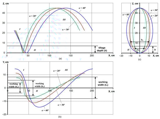
Figure 8.
Trajectories of points on the blade edge of the rotary tillage tool during 1 revolution in the XOY (a), XOY (b), and YOZ (c) planes depending on the angle of attack α at a kinematic coefficient of η = 1.0.
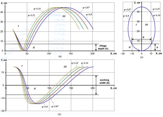
Figure 9.
Trajectories of points on the blade edge of the rotary tillage tool during 1 revolution in the XOY (a), XOY (b), and YOZ (c) planes depending on the kinematic coefficient η at an angle of attack of α = 40°.
The maximum tilling depth h is illustrated in Figure 8a and Figure 9a, while the furrow width b is shown in Figure 8b and Figure 9b. The transverse projections (YOZ plane) of the trajectory are presented in Figure 8c and Figure 9c.
The period during which point M on the blade edge is in the soil is determined by the angles θh1 and θh2 (Figure 10). The first angle θh1 corresponds to the position of the radius-vector CM at the moment when point M enters the soil, and the second angle θh2 corresponds to the moment when it exits the soil. The angles θh1 and θh2 are determined from Equation (1) under the condition Z = h:
or
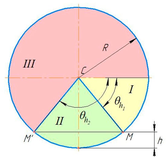
Figure 10.
Scheme for determining phases of motion of the tillage tool.
The motion cycle can be divided into three phases (Figure 9 and Figure 10): phase I is initial movement when θ < θh1 (yellow zone), phase II is soil treatment (penetration and lifting out) when θh1 < θ < θh2 (green zone), and phase III is completion of the cycle when θ > θh2 (red zone).
The presented graphs show that increasing the angle of attack α leads to longer motion trajectories and a slight increase in working width, while higher values of the kinematic coefficient η result in shortened path lengths with no change in the tool’s working width.
Next, the motion characteristics of point M on the blade edge of the rotary tillage tool were analyzed in the horizontal plane (Phase II). Figure 11 illustrates a top view of the edge point trajectory during the soil treatment phase (XOY plane): point A marks the moment of penetration into the soil, followed by maximum penetration into the tilling depth h, and point B indicates the moment of lifting out from the soil. This motion pattern applies to any point on the edge of the tillage tool during soil treatment.
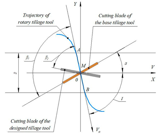
Figure 11.
Scheme for determining angle β.
The line AOB represents the trajectory projection of the edge point M in the furrow (horizontal plane XOY). Through the lowest point O, corresponding to θ = 90°, we construct a tangent line inclined from the forward travel direction (OX axis) by angle γ. This tangent line intersects the furrow profile along points AOB of the trajectory and represents the horizontal projection of the vector of absolute velocity Va. Therefore, angle γ characterizes the inclination of the vector of absolute velocity Va of the rotary tillage tool in the forward travel direction.
Angle β between the cutting blade edge and vector of absolute velocity Va of the edge point of the base tillage tool is determined as follows:
The necessary condition for soil sliding along the cutting blade in the horizontal plane is [28,29]
where φ1 is the friction angle between the soil and tillage tool interface.
We determined the angle γ between the forward travel direction V (axis OX) and the trajectory tangent line in the horizontal XOY plane (vector of absolute velocity Va) during penetration of the edge point M into the soil. This angle is calculated as
where dY and dX are differentials of the functions Y and X.
From Equation (1), we obtain the differentials dY and dX:
Substantiating the expression in (12) into (11) yields
The most characteristic phase of soil treatment occurs when the tillage tool reaches the maximum penetration depth at θ = 90° (furrow bottom position), for which Equation (14) becomes [30]
Substantiating (15) into (10) gives angle β for the base tillage tool:
Figure 12 demonstrates the functional dependence of the inclination angle β of the cutting blade on the kinematic coefficient η for various angles of attack, α, in the base tillage tool.
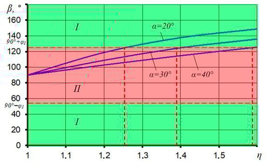
Figure 12.
Effect of kinematic coefficient η and angle of attack α on angle β of the base tillage tool. I—soil sliding zone; II—non-sliding zone.
The graph shows that when η = 1.0, angle β equaled 90° for all angles of attack. It should be noted that for this value of the kinematic coefficient, the vector of absolute velocity Va aligned precisely with the rotation axis of the rotary tillage tool for the angles of attack 20° < α < 40°. With further increase in the kinematic coefficient η, angle β continuously grew. The growth intensity depended on the angle of attack α. For an angle of attack of 40° and at the kinematic coefficient η = 1.1, angle β = 97°. When the kinematic coefficient η increased to 1.6, angle β grew to 126°, representing a 30% increase. For the angle of attack 20°, at the kinematic coefficient η = 1.1 angle β was 105°. Increasing the kinematic coefficient η to 1.6 led to angle β growth to 149°, meaning a 42% increase.
The value of angle β also depended on the angle of attack α. Larger angles of attack, α, corresponded to smaller values of angle β. This difference increased with growth in the kinematic coefficient η. For example, at the angle α = 40° and kinematic coefficient η = 1.1, angle β equaled 97°. For the angle of attack 20° and kinematic coefficient η =1.1, this angle was 105°, i.e., 8° larger. When kinematic coefficient η increased to 1.6 for these angles of attack, β equaled 126° and 149°, respectively. In this case, the difference between angles β reached 23°.
The green-shaded zone I in the graph corresponds to Condition (9), showing that soil sliding along the cutting blade of the base tillage tool only occurred at non-optimal kinematic coefficients, η, exceeding 1.25, 1.37, and 1.57 for angles of attack, α, of 20°, 30°, and 40°, respectively. This demonstrates that effective soil sliding requires substantially high rotational speeds, leading to increased energy requirements. According to Nalavade P.P. et al., Amantayev et al., the absence of soil sliding under free-rotation or low-speed conditions results in soil accumulation in front of the cutting blade of the tillage tool, subsequently increasing energy requirements and reducing tillage performance quality [7,8].
To achieve effective soil sliding at optimal kinematic coefficient η = 1.0–1.2, the cutting blade of the designed tillage tool should be positioned at an inclination angle β < 90 − φ1 relative to the vector of absolute velocity Va. This inclination angle β for the designed tillage tool can be determined as
Considering the angle of attack α of the designed tillage tool, the optimal inclination angle β according to Criterion (11) should be selected within the range of 38–42°.
Hence, this specific angular orientation ensures continuous soil sliding along the cutting blades while preventing soil accumulation and fixed soil body formation. As a result, this approach reduces power requirements while enhancing tillage quality performance.
The base ring disc tillage tool features a circular edge of the cutting blade lying in the plane F1 (Figure 13), oriented perpendicular to the vector of absolute velocity Va. This configuration prevents soil sliding along the cutting blade. During motion, the edge point’s trajectory describes a cylindrical surface.
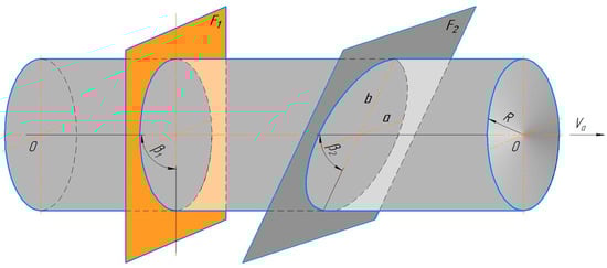
Figure 13.
Scheme of positioning of cutting blade: circular configuration at β1 = 90° (base tillage tool) and elliptical configuration at β2 < 90 − φ1 (designed tillage tool).
By introducing the inclined plane F2 at angle β < 90 − φ1 to the vector Va, the cylindrical section transforms into an elliptical profile with semi-axes defined by
This design configuration satisfies the soil sliding conditions along the cutting blade.
Thus, the cutting blades of the designed tillage tool, oriented at an acute angle β to the vector of absolute velocity Va, should feature elliptical profiles with curved cutting edge.
3.2. Results of Field Experiments
The analysis of results included two aspects: one was the energy efficiency performance, and the other was the tillage quality.
3.2.1. Energy Efficiency
Field experimental studies revealed a significant effect of the kinematic coefficient η and angle of attack α on the specific energy efficiency parameters of the designed PTO-powered rotary tillage tools.
Figure 14 illustrates the effects of the kinematic coefficient η and angle of attack α on the specific draught force RX and specific torque T.
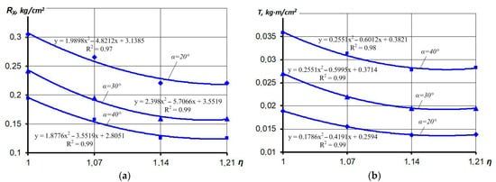
Figure 14.
Effect of the kinematic coefficient η and angle of attack α of the designed rotary tillage tools on (a) specific draught force RX and (b) specific torque T.
Analysis shows that with an increase in the kinematic coefficient η from 1.0 to 1.21, the specific draught force of the tillage tools reduced by 1.3–1.5 times. With the increase in the angle of attack from 20° to 40°, the specific draught force of the tillage tools decreased by 1.5–1.7 times (with a coefficient of variation of 12.6% < Vx < 48.9%) (Figure 14a). This behaviour of reduced draught force at higher kinematic coefficients and angles of attack agreed well with experimental studies of PTO-powered tillage discs of Nalavade et al., Hann and Giessibl, and Upadhyay and Raheman [7,11,13,14].
The specific torque T required for driving the tillage tools decreased by 1.1–1.4 times with an increase in the kinematic coefficient from 1.0 to 1.21, and it increased by 1.8–2.0 times with an increase in the angle of attack from 20° to 40° (with a coefficient of variation of 10.8% < Vx < 48.5%) (Figure 14b). This behaviour of torque requirement at higher kinematic coefficients also agreed well with findings of Hann and Giessibl, and Nalavade et al. [7,11].
In Figure 15, the effect of the kinematic coefficient η and angle of attack α of the designed rotary tillage tools on specific total power requirements, No, for the soil tillage process is presented. The graph shows that with an increase in the kinematic coefficient η from 1.0 to 1.21, the specific total power requirements No first decreased and then increased for all angle-of-attack values. With an increase in the angle of attack from 20 to 40°, the specific total power requirements reduced by 1.2–1.3 times.
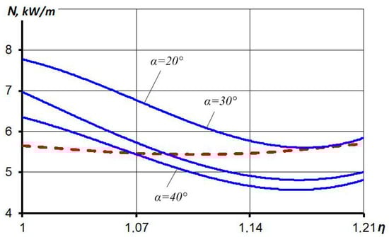
Figure 15.
Effect of the kinematic coefficient η and angle of attack α of the designed rotary tillage tools on specific total power requirements, N, for the soil tillage process:  —rotary tillage tools;
  —base ring disc tillage tools at α = 40°.
—rotary tillage tools; —base ring disc tillage tools at α = 40°.
The research results reveal that the specific total power requirements N for the soil treatment process were minimum when the kinematic coefficient η equaled 1.14–1.21 and the angle of attack was 40°, with this value being 4.5–4.7 kW/m. This behaviour agreed well with prior experimental studies of PTO-powered rotary tillage discs by Hann and Giessibl, Nalavade et al., and Upadhyay and Raheman [1,7,11,13,14].
A comparative assessment of the tillage tools shows that the PTO-powered rotary tillage tool with elliptical cutting blades had 14–16% lower specific total power requirements, N, than the PTO-powered ring disc tillage tool.
Thus, these experimental findings confirm the theoretical analysis that providing soil sliding along the cutting blades inclined at an angle of β < 90 − φ1 reduces draught force and total power requirements in the designed PTO-powered rotary tillage tools, operating at low values of kinematic coefficient. These findings agree well with and are confirmed by the experiment results of Hann et al. and Wells et al. [11,20]. Using the designed tools, this improvement occurs by preventing soil accumulation and fixed soil body formation, demonstrating superior performance compared to base ring disc tillage tools during surface soil treatment. This finding also supported by the experimental data of Aluko and Seig and Amantayev et al. [28,29].
3.2.2. Tillage Quality
The effect of the kinematic coefficient η on tillage quality produced by the designed PTO-powered rotary tillage tool with elliptical cutting blades was assessed simultaneously with force measurement tests under identical soil conditions at the optimal angle of attack α = 40° of the tillage tool, selected based on minimum total power requirements for surface soil treatment (Figure 16). The green-shaded zones in the graphs indicate the operational range that satisfy tillage quality requirements [18].
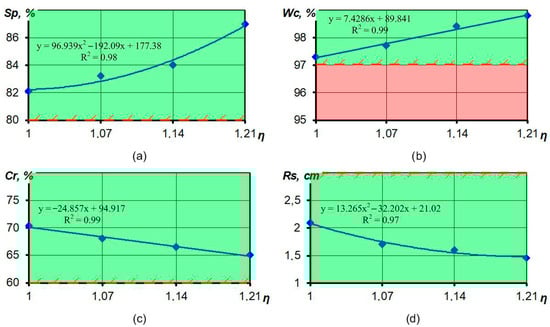
Figure 16.
Effect of the kinematic coefficient η on tillage quality of the designed rotary tillage tool: (a)—soil pulverization; (b)—weed cutting; (c)—crop residue retention; (d)—roughness of the field soil surface.
Analysis of the research results shows that with the increase in the kinematic coefficient η from 1.0 to 1.21, soil pulverization increased (by 5–7%), weed cutting increased (by 1–2%), retaining the crop residue decreased (by 7–8%), and roughness of the field soil surface reduced (by 30–31%). Thus, for all of the kinematic coefficients η, the tillage quality produced by the designed rotary tillage tool meets tillage quality requirements [18], namely soil pulverization no less than 80%, weed cutting no less than 97%, crop residue retention no less than 60%, and roughness of the field soil surface no more than 3 cm. The obtained data agreed well with the experiment results of Wells et al., Hoki et al., and Salokhe et al. [9,20,31].
Thus, the research results show that the use of the designed PTO-powered rotary tillage tools on surface soil treatment provides the required tillage quality.
3.2.3. Discussion
Development of a new PTO-powered rotary tillage tool with elliptical cutting blades is aimed at solving the fundamental problem of enhancing the energy efficiency of surface soil treatment by improving the process of tillage tool–soil interaction. Conventional free-rolling and PTO-powered rotary tillage discs with circular blade profiles are prone to soil mass accumulation and compacted soil body formation at their interface. This leads to increased draught force, thereby decreasing the operational and energy efficiency [7,10]. This problem particularly occurs at lower kinematic coefficients due to the lack of soil sliding. These issues of conventional designs are well studied in the literature. Nalavade et al. and Amantayev et al. experimentally confirmed that soil mass accumulation occurs in front of tillage discs during operation, creating compressive forces that increase draught requirements [7,8]. This phenomenon was also observed by Chertkiattipol and Niyamapa in studies on tillage tools of rotary tillers [25]. However, the high operational rotational speed of these tillage tools (which have various types of cutting blades and are installed without an angle of attack) leads to a significant increase in energy requirements. Most research has focused on optimizing the design of cutting blades to reduce torque and total power requirements [21,22,23,24,25]. A comprehensive analysis of key studies on rotary tillage tools, including their findings, is summarized in Table 1.

Table 1.
Analysis of key studies on rotary tillage tools.
Hann and Giessibl also demonstrated that although powered tillage disc operation reduces specific draught force, it typically increases torque, leading to higher total power requirements, especially at higher kinematic coefficients [11]. They identified the optimal efficiency range at kinematic coefficients of 1.0–1.2. Wells et al. [20] also confirm that to minimize power requirements, the kinematic coefficient should be as low as possible while still achieving proper tillage action.
The new PTO-powered rotary tillage tool addresses these problems through the use of elliptical-profile cutting blades inclined at an optimal angle β. This design prevents soil mass accumulation by ensuring smooth soil sliding during operation at low kinematic coefficients (η = 1.0–1.21). The methodological approach for investigating this new tillage tool is comprehensive and combines theoretical analysis with kinematic modelling and field studies.
Theoretical studies enabled the analysis of motion trajectories and the identification of three distinct operational phases based on the rotation angles θh1 and θh2. The developed kinematic model provided crucial insight into the mechanism of soil–tool interaction during the soil treatment phase. This staged approach confirmed that effective soil sliding along the cutting blade of disc tillage tools did not occur within the optimal kinematic range of η = 1.0–1.2 for all angles of attack, underscoring the need for improving the design of traditional tillage discs. A ring tillage disc with circular cutting blade for surface soil treatment was selected as the base tillage tool. The determination of the optimal blade inclination angle β = 38–42° and its elliptical-profile configuration represents a significant advancement, as these parameters ensure the conditions for smooth soil sliding (β < 90 − φ1) throughout the entire working period. These results agree well with the fundamental principles of soil–tine interaction established by Aluko and Seig and Amantayev et al. [28,29].
The experimental results demonstrate the practical validation of the theoretical foundation. The reduction in specific draught force (1.3–1.5 times) and torque (1.1–1.4 times) with increasing kinematic coefficient confirms the effectiveness of the elliptical blade design in reducing soil resistance, which aligns with the findings of Nalavade et al., Hann and Giessibl, and Upadhyay and Raheman [7,11,13,14]. The minimal specific total power requirements of 4.5–4.7 kW/m at the kinematic coefficient η = 1.14–1.21 and the angle of attack α = 40° demonstrated a 14–16% reduction in energy requirements compared to the base tillage tool. These findings confirm the conclusions of Hann and Giessibl and Wells et al. that the kinematic coefficient should be selected in the range of 1.0–1.2 to minimize power requirements [11,20]. Thus, these results demonstrate a solution to the problem of reducing energy requirements, which is highly relevant for the development of tillage implements of a new generation.
The newly designed PTO-powered rotary tillage tool also provided high tillage quality, meeting all requirements of the Interstate Standard GOST 33687-2015 across all measured parameters throughout the tested range of kinematic coefficients: soil pulverization ≥ 80%, weed cutting ≥ 97%, crop residue retention ≥ 60%, and field surface roughness ≤ 3 cm [27].
Thus, this research provides scientifically grounded solutions for the development of energy-efficient rotary tillage tools and represents fundamental work in soil dynamics, making a significant contribution to agricultural engineering science.
4. Conclusions
The purpose of this research was to design a kinematically optimized PTO-powered rotary tillage tool with elliptical cutting blades and to evaluate its performance in terms of energy efficiency and tillage quality. The research focused on optimizing geometric and kinematic parameters—the blade inclination angle β, elliptical-profile configuration, kinematic coefficient η, and angle of attack α—to prevent soil mass accumulation by providing the soil sliding along the blade interface. Field experiments confirmed the tool’s effectiveness, demonstrating significant energy saving and superior tillage quality compared to base rotary tillage discs. The main findings are summarized as follows:
- This study introduces a new PTO-powered rotary tillage tool with individual cutting blades for surface soil treatment. The novelty of this design lies in the inclination of each blade at an acute angle β relative to the vector of absolute velocity Va during soil penetration and operation at low kinematic coefficients of 1.0–1.2. Analysis of conventional rotary tillage tools revealed that soil accumulation on their interface decreases operational efficiency, while PTO operation at high rotational speeds increases energy requirements. This study demonstrated that the proposed design prevents soil mass accumulation and fixed soil body formation by ensuring smooth soil sliding along the cutting blades at low kinematic coefficients, thereby enhancing both energy efficiency and tillage quality.
- A kinematic model of the rotary tillage tool was developed, which enabled the plotting of motion trajectories as functions of the angle of attack α and kinematic coefficient η. The motion cycle was divided into three phases: initial movement, soil treatment (penetration and lifting out), and completion of the cycle. The analysis of soil–tool interaction during soi treatment phase established a significant dependence of the blade inclination angle β on the kinematic coefficient η and angle of attack α. It was found that effective soil sliding along the cutting blade of the base tillage tool does not occur within the kinematic coefficient of η = 1.0–1.2 for angles of attack. Theoretical analysis derived the equation for determining the optimal angle of inclination of the cutting blade of the designed tillage tool and substantiated the optimal inclination angle β = 38–42° and its elliptical-profile edge configuration.
- Field experiments confirmed the theoretical analysis, showing that maintaining soil sliding along the cutting blades through an inclination angle of β < 90 − φ1 reduces the total power requirements of the designed rotary tillage tools. The results demonstrated that specific total power requirements for surface soil treatment reach minimum values at kinematic coefficient η = 1.14–1.21 and an angle of attack of 40°. Compared to base ring disc tillage tools, the new designed PTO-powered rotary tillage tools reduce specific total power requirements by up to 14–16%, indicating higher energy efficiency.
- The tillage quality produced by the designed tillage tools satisfies all requirements, achieving soil pulverization ≥ 80%, weed cutting ≥ 97%, crop residue retention ≥ 60%, and roughness of the field soil surface ≤ 3 cm.
Author Contributions
Conceptualization, M.A. and Y.D.; methodology, M.A. and Y.D.; software, Y.W.; validation, M.A., Y.D. and Y.W.; formal analysis, Y.W.; investigation, M.A. and Y.D.; resources, Y.W.; data curation, B.Q.; writing—original draft preparation, M.A. and Y.D.; writing—review and editing, Y.W. and B.Q.; visualization, Y.W. and H.Z.; supervision, M.A. and Y.D.; project administration, W.Z.; funding acquisition, W.Z. All authors have read and agreed to the published version of the manuscript.
Funding
This research was supported by the National Natural Science Foundation of China (52205274), the Innovation Program of Chinese Academy of Agricultural Sciences (CAAS-SAE-202301), and Bolashak International scholarship (“500 scientists” project) of the Republic of Kazakhstan.
Institutional Review Board Statement
Not applicable.
Informed Consent Statement
Not applicable.
Data Availability Statement
The datasets used and/or analyzed during the current study are available from the corresponding author on reasonable request.
Conflicts of Interest
The authors declare no conflicts of interest.
References
- Nalavade, P.P.; Soni, P.; Salokhe, V.M.; Niyamapa, T. Application of powered disc implements for efficient on-farm residue management: A review. Int. Agric. Eng. J. 2011, 20, 1–7. [Google Scholar]
- Sugirbay, A.; Zhao, K.; Liu, G.; Hu, G.; Chen, J.; Mustafin, Z.; Iskakov, R.; Kakabayev, N.; Muratkhan, M.; Khan, V.; et al. Double Disc Colter for a Zero-Till Seeder Simultaneously Applying Granular Fertilizers and Wheat Seeds. Agric. 2023, 13, 1102. [Google Scholar] [CrossRef]
- Qin, K.; Ding, W.M.; Ahmad, F.; Fang, Z.C. Design and experimental validation of sliding knife notch-type disc opener for a no-till combine harvester cum seed drill. Int. J. Agric. Biol. Eng. 2018, 11, 96–103. [Google Scholar] [CrossRef]
- Ahmad, F.; Qiu, B.; Ding, Q.; Ding, W.; Khan, Z.M.; Shoaib, M.; Chandio, F.A.; Rehim, A.; Khaliq, A. Discrete element method simulation of disc type furrow openers in paddy soil. Int. J. Agric. Biol. Eng. 2020, 13, 103–110. [Google Scholar] [CrossRef]
- Perdok, U.; Kouwenhoven, J. Soil-tool interactions and field performance of implements. Soil Tillage Res. 1994, 30, 283–326. [Google Scholar] [CrossRef]
- Zoz, F.M.; Grisso, R.D. Traction and Tractor Performance. In Proceedings of the 2003 Agricultural Equipment Technology Conference, Louisville, KY, USA, 9–11 February 2003; ASAE: St. Joseph, MI, USA, 2003; pp. 1–47. [Google Scholar]
- Nalavade, P.P.; Salokhe, V.M.; Niyamapa, T.; Soni, P. Performance of free rolling and powered tillage discs. Soil Tillage Res. 2010, 109, 87–93. [Google Scholar] [CrossRef]
- Nalavade, P.P.; Soni, P.; Salokhe, V.M.; Niyamapa, T. Development of a powered disc harrow for on-farm crop residue management. Int. Agric. Eng. J. 2013, 22, 49–60. [Google Scholar]
- Salokhe, V.M.; Islam, M.S.; Gupta, C.P.; Hoki, M. Field testing of a PTO powered disk tiller. J. Terramechanics 1994, 31, 139–152. [Google Scholar] [CrossRef]
- Amantayev, M.A.; Gaifullin, G.Z.; Kushnir, V.G.; Nurushev, S.Z.; Kravchenko, R.I. Soil Body Formation in Front of The Rotary Tillage Tools. Biosci. Biotechnol. Res. Asia 2016, 13, 1983–1988. [Google Scholar] [CrossRef]
- Hann, M.J.; Giessibl, J. Force Measurements on Driven Discs. J. Agric. Eng. Res. 1998, 69, 149–157. [Google Scholar] [CrossRef]
- Upadhyay, G.; Raheman, H. Effect of velocity ratio on performance characteristics of an active-passive combination tillage implement. Biosyst. Eng. 2020, 191, 1–12. [Google Scholar] [CrossRef]
- Upadhyay, G.; Raheman, H. Specific draft estimation model for offset disc harrows. Soil Tillage Res. 2019, 191, 75–84. [Google Scholar] [CrossRef]
- Upadhyay, G.; Raheman, H. Comparative assessment of energy requirement and tillage effectiveness of combined (active-passive) and conventional offset disc harrows. Biosyst. Eng. 2020, 198, 266–279. [Google Scholar] [CrossRef]
- Kumar, S.; Singh, T.P. Assessment of Power Requirement of a Powered Disc through Soil Bin Study. Int. J. Basic Appl. Agric. Res. 2015, 13, 44–51. [Google Scholar]
- Kumar, S.; Singh, T.P. Assessment of Power, Energy and Torque of Powered Disc through Soil Bin Study. J. Agric. Eng. 2016, 53, 1–9. [Google Scholar] [CrossRef]
- Singh, T.; Singh, B. Effect of gang speed, λ -ratio and depth of operation on the performance of powered vertical disc plough. J. Agric. Eng. 2000, 37, 1–12. [Google Scholar] [CrossRef]
- Kumar, S.; Singh, T.P. Development and Performance Evaluation of a PTO Powered Vertical Disc Plough with Seeding Attachment for Sowing of Wheat after Rice. J. Agric. Eng. 2019, 56, 147–157. [Google Scholar] [CrossRef]
- Nalavade, P.P.; Soni, P.; Salokhe, V.M.; Niyamapa, T. Comparative performance of standard, notched and spiral-notched tillage discs. Int. Agric. Eng. J. 2011, 20, 18–26. [Google Scholar]
- Wells, L.G.; Smith, E.M.; Hammett, D.E. Analysis and testing of powered tillage blades. Trans. ASAE 1980, 26, 1379–1382. [Google Scholar] [CrossRef]
- Zhang, X.; Hu, X.; Zhang, L.; Kheiry, A.N.O. Simulation and structural parameter optimization of rotary blade cutting soil based on SPH method. Int. J. Agric. Biol. Eng. 2024, 17, 82–90. [Google Scholar] [CrossRef]
- Yang, Y.; Fielke, J.; Ding, Q.; He, R. Field experimental study on optimal design of the rotary strip-till tools applied in rice-wheat rotation cropping system. Int. J. Agric. Biol. Eng. 2018, 11, 88–94. [Google Scholar] [CrossRef]
- Matin, A.; Hossain, I.; Gathala, M.K.; Timsina, J.; Krupnik, T.J. Optimal design and setting of rotary strip-tiller blades to intensify dry season cropping in Asian wet clay soil conditions. Soil Tillage Res. 2021, 207, 104854. [Google Scholar] [CrossRef]
- Zhang, X.; Zhang, L.; Hu, X.; Wang, H.; Shi, X.; Ma, X. Simulation of Soil Cutting and Power Consumption Optimization of a Typical Rotary Tillage Soil Blade. Appl. Sci. 2022, 12, 8177. [Google Scholar] [CrossRef]
- Chertkiattipol, S.; Niyamapa, T. Variations of torque specific energy for different rotary blades. J. Int. Agric. Eng. 2010, 19, 1–14. [Google Scholar]
- Interstate Standard GOST 34631-2019; Agricultural Machinery. Methods of Power Estimation; Standartinform: Moscow, Russia, 2020. (In Russian)
- Interstate Standard GOST 33687-2015; Machinery and Tools for Surface Treatment of Soil. Test Methods; Standartinform: Moscow, Russia, 2016. (In Russian)
- Aluko, O.B.; Seig, D.A. An experimental investigation of the characteristics of and conditions for brittle fracture in two-dimensional soil cutting. Soil Tillage Res. 2000, 57, 143–157. [Google Scholar] [CrossRef]
- Amantayev, M.; Gaifullin, G.; Nukeshev, S. Modelling of the soil–two-dimensional shearing tine interaction. Bulg. J. Agric. Sci. 2017, 23, 882–885. Available online: https://agrojournal.org/23/05-28.html (accessed on 1 August 2025).
- Amantayev, M.; Gaifullin, G.; Kravchenko, R.; Kushnir, V.; Nurushev, S. Investigation of the furrow formation by the disc tillage tools. Bulg. J. Agric. Sci. 2018, 24, 704–709. Available online: https://agrojournal.org/24/04-24.html (accessed on 1 August 2025).
- Hoki, M.; Burkhardt, T.H.; Wilkinson, R.H.; Tanoue, T. Study of PTO driven powered disk tiller. Trans. ASAE 1988, 31, 1355–1360. [Google Scholar] [CrossRef]
Disclaimer/Publisher’s Note: The statements, opinions and data contained in all publications are solely those of the individual author(s) and contributor(s) and not of MDPI and/or the editor(s). MDPI and/or the editor(s) disclaim responsibility for any injury to people or property resulting from any ideas, methods, instructions or products referred to in the content. |
© 2025 by the authors. Licensee MDPI, Basel, Switzerland. This article is an open access article distributed under the terms and conditions of the Creative Commons Attribution (CC BY) license (https://creativecommons.org/licenses/by/4.0/).