Abstract
The discrete element method (DEM), based on particle dynamics, is used to simulate the technological process of soil tillage using agricultural machinery. A key aspect of the DEM for obtaining accurate agrotechnical and energy indicators of soil cultivation is the formulation of particle contact rules, determined by normal and tangential interactions as well as cohesion forces. This study presents a comprehensive analysis of discrete element method (DEM) contact models used to simulate soil cultivation processes. This study addresses a key issue—the absence of a systematic approach to selecting adequate contact models, which limits the accuracy of predicting soil behavior during interaction with agricultural machinery. A detailed classification of 17 combinations of contact models implemented in the commercial software Rocky DEM was performed, grouped into three categories: normal force models (Linear Spring [LSP], Hysteresis [HLS], Hertzian [HSD]), tangential force models (Coulomb, linear spring limit [linear], Mindlin–Deresiewicz), and cohesive force models (linear cohesion [linear], constant force [constant], Johnson–Kendall–Roberts [JKR]). Experimental validation was conducted by analyzing the angle of repose for various soil types (sandy loam, light loam, medium loam, and heavy clay) with moisture contents ranging from 11 to 31%. This analysis identified the nine most effective combinations of contact models to describe normal, tangential, and cohesive forces (LSP–Coulomb–linear, HLS–linear–linear, HLS–Coulomb–linear, HSD–linear–linear, HSD–linear–JKR, HSD–Coulomb–linear, HSD–Coulomb–JKR, HSD–Mindlin–Deresiewicz–linear, HSD–Mindlin–Deresiewicz–JKR), which showed reliable agreement with experimental angle of repose measurements at approximately 85% accuracy. This study significantly contributes to advancing computer modeling methods in agriculture by providing a scientifically grounded approach for selecting DEM contact models.
1. Introduction
To simulate the technological process of soil tillage with tillage machines, various numerical methods are applied depending on the physical and mechanical properties of the environment being simulated. These methods include the finite element method (FEM), the discrete element method (DEM), the computational fluid dynamics (CFD) method, and the smoothed particle hydrodynamics (SPH) method. Recently, the discrete element method has gained prominence in research.
The analysis in [1] demonstrates that the finite element method (FEM) facilitates assessment of the soil’s stress–strain state; however, modeling soil particle displacement, cracking, and deformation during tillage remains challenging using this method.
Ref. [1] further highlights the primary advantage of computational fluid dynamics (CFD) and smoothed particle hydrodynamics (SPH) over the FEM and DEM: they have the ability to assess pressure distribution within the soil under working tools and the pressure exerted by the soil on tool surfaces, enabling evaluation of tool wear. However, unlike the DEM, CFD does not allow for the evaluation and visualization of soil aggregate fragmentation and particle movement. Consequently, the DEM is currently regarded as the most promising method for modeling technological processes in soil tillage.
The discrete element method (DEM) is a particle-based modeling approach. As described by its founder Cundall [2], the DEM simulates the mechanical behavior of systems composed of particles interacting with rigid or deformable bodies. This method effectively accounts for the heterogeneous nature of soil and substantial displacement of soil particles caused by interaction with tillage implements. The DEM facilitates the prediction of both soil microdynamics (e.g., forces and displacements of individual particles) and macro-scale phenomena, including cutting forces and soil disturbances.
A fundamental aspect of the DEM is defining contact laws governing interactions between particles (Figure 1). Based on these laws, equations of motion for the particles are formulated, considering both body forces and external forces acting on the system. The overall system behavior is determined by solving these equations of motion.
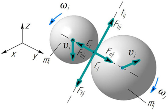
Figure 1.
A diagram of discrete particle interactions. i, j—indices of spherical particles; ωi, ωj—angular velocities of particles i and j, s−1; mi, mj—masses of particles i and j; Ci, Cj—centers of gravity of particles i and j; Fnij—normal contact force from particle i to particle j, N; Fnji—normal contact force from particle j to particle i, N; Ftij—tangential force from particle i to particle j, N; Ftji—tangential force from particle j to particle i, N; υi, υj—linear velocities of particles i and j, m/s.
Contact forces arising during particle interactions are commonly divided into normal (Fn) and tangential (Ft) components relative to the contact surface. These forces govern the dynamics of particle interactions. Additionally, cohesion resulting from adhesive and/or cohesive forces must be included in the contact interaction model, especially for moist soils.
The process of particle interaction and movement (Figure 1) represents the mechanical equilibrium of a bulk material particle.
where is the mass of the i-th particle; is the velocity vector of the center of mass; ωi is the angular velocity vector; b is the body force vector; is the moment of inertia; is the force acting on the particle through contact with another particle; Tc is the external torque arising from particle contact; and Mr is the rolling resistance torque.
Contact interaction characteristics are represented by linear or nonlinear functions that accurately capture the material’s physical behavior. Rheological models of different materials, or their combinations, serve as contact models. Rheological models can be used to describe both normal and tangential interactions of discrete particles, as well as to account for particle cohesion due to adhesion cohesion forces. Zhao H. et al. [3], who analyzed DEM contact models, indicate that soil models can be classified as cohesive or non-cohesive depending on the soil’s cohesive properties Given the complexity of soil particle interactions, DEM contact models can be classified according to the following criteria:
- Contact models for describing normal forces;
- Contact models for describing tangential forces;
- Contact models that allow us to take into account the adhesion and cohesion of particles.
Table 1 presents the contact models of the discrete element method according to this classification.

Table 1.
Discrete element method contact models used in modeling tillage processes.
The simplest contact model is the linear spring contact model (Section 1.1, Table 1). This model is linearly elastic and frequently used to simulate soil–tillage tool interactions [4,5,6,7]. This model does not account for the nonlinearity of loading–unloading cycles, plastic soil deformation, or the adhesive and cohesive properties of soil particles. Although widely used in DEM research, the linear spring contact model generally exhibits lower accuracy than the hysteresis linear spring model, since energy dissipation in soils is predominantly plastic rather than viscous. Its accuracy decreases particularly when particles have multiple simultaneous contacts, as viscous dissipation is accurately modeled only for single contacts [38].
The hysteresis spring contact model (Section 1.2, Table 1) incorporates plastic deformation into the contact mechanics equations, with particles behaving elastically up to a defined stress threshold. When this threshold is exceeded, particles plastically deform, allowing for large overlaps without excessive force, reflecting the material’s compressibility. The normal force in the hysteresis spring model is calculated according to the Walton–Brown theory (Walton O.R., Braun R.L.) [39].
The Hertz–Mindlin contact model (Section 1.2, Table 1) [16,17,18,19,20,21] is the most widely adopted for simulating soil–implement interactions, particularly when coupled with the Parallel Bond Model [20,21,22,23,24,25,26,27,28]. However, it has been noted that this model, similar to the nonlinear elastic contact model, lacks accuracy in predicting the vertical component of traction forces.
To account for tangential forces in particle interactions, the following contact models are employed:
In the Coulomb Linear Spring Limit Model, tangential force is modeled as an elastic–frictional interaction. This model can be combined with both the hysteresis linear spring model (Section 1.2) and the linear spring model (Section 1.1) for normal forces.
The tangential force for the Coulomb limit is determined by the frictional force through the normal contact force and the coefficient of friction. The slipping condition considered in this model is based on the tangential component of the relative velocity [38]. The Coulomb Limit Model works with all three types of normal force models, i.e., with the hysteresis linear spring model (Section 1.2, Table 1), the linear spring model (Section 1.1, Table 1), and the Hertz damping model (Section 1.3, Table 1).
The linear Coulomb Spring Limit and Coulomb Limit Model have been rarely used in DEM soil modeling.
Within the Mindlin–Deresiewicz elastic–viscous interaction framework, the frictional tangential force is governed by the tangential dashpot coefficient, derived from the coefficient of restitution—the ratio of particle velocities before and after collision [38]. The Mindlin–Deresiewicz Model works only with the Hertz model for normal forces (Section 1.3, Table 1). This model is mainly used in research on soil modeling using the discrete element method.
Real soils exhibit varying degrees of adhesion and cohesion between particles and the working surface, as well as tangential interactions. The attractive pressures (i.e., adhesion and adhesion/cohesion forces) arise from capillary action and water bridges existing between particles in unsaturated soils. Therefore, contact models that account for adhesion and cohesion provide a more accurate description of soils in the discrete element method.
Contact models incorporating soil particle cohesion are presented in Sections 3.1–3.5 of Table 1.
When the linear cohesion model (Section 3.1) is used, the cohesive force or adhesion force is added to the normal force component of the contact model originally developed for non-cohesive soils. Although the linear cohesion model itself does not include a tangential component, its addition increases the normal force, which consequently increases the friction force for greater resistance to slippage. The linear cohesion model can be added to any of the three contact models presented in paragraphs 1.1–1.3 of Table 1, i.e., the hysteresis linear spring (Section 1.2), linear spring (Section 1.1) and Hertz damping models (1.3) [38,40]. This model has been used in the works of researchers such as Tamas, K. and Bernon, L. [41], Tamás, K. et al. [17], and Obermayr, M. et al. [42].
The Parallel Bond Model (Section 3.2, Table 1) is an adaptation of the Hertz–Mindlin contact model, developed by Potyondy D.O. and Cundall P.A. [43]. Cohesion in this model is represented by rectangular or cylindrical cement elements, modeled as parallel beam-like connections at the contact points between particles [43]. These connections are modeled as elastic beams, the lengths of which approach zero and can be represented by sets of springs evenly distributed along the contact plane and centered at the point of contact [44]. After the connection is formed, in addition to contact forces, normal and tangential forces and connection moment are also calculated [25]. As a result, the connection can withstand and transfer forces and moments between particles. Bond failure occurs when the maximum allowable normal or shear strength is exceeded [28]. As pointed out by Tamás, K. et al. [17] and Van der Linde J. [45], the Parallel Bond Model is able to more realistically simulate the formation of lumps and the crumbling of agricultural soils. This model is the most widely used in soil tillage research [16,17,23,24,25,26,27,28,45,46]. Given that the Parallel Bond Model operates exclusively with the Hertz–Mindlin normal force model (Section 1.3, Table 1), its inability to accurately predict the vertical component of traction forces is recognized as a limitation [40].
Another model to account for soil particle cohesion is the Johnson–Kendall–Roberts (JKR) cohesion model [47], which retains the tangential contact force and the normal and tangential Hertz–Mindlin damping forces, but modifies the normal contact force to include cohesion (Section 3.3, Table 1). This modification allows for the modeling of strong adhesive bonds that exist in wet materials (e.g., wet soil) and captures the effects of van der Waals forces due to contact between two surfaces. Rather than explicitly considering surface and interfacial energies, this model calculates adhesion force as the product of specific adhesion energy density per unit volume (J/m3) or per unit area (J/m2) over the circular contact area between particles. The Johnson–Kendall–Roberts model works with the hysteresis spring contact model (Section 1.2) and Hertz–Mindlin model (Section 1.3) for normal forces. This model was used in modeling the soil tillage process in [18,29,30].
In [48], the Hertz–Mindlin model coupled with both the JKR contact adhesion model and the linear adhesion contact model was employed to predict soil deformation zones and traction forces; the authors reported comparable accuracy for both approaches.
In the Edinburgh Elastic–Plastic Adhesion Model (Section 3.4, Table 1), a nonlinear hysteresis spring model is used to account for elastic–plastic contact deformation and components of the adhesion or cohesion forces (tear-off forces) acting between dissimilar or similar materials, based on the assumption that this force increases with increasing plastic contact area [49]. The Edinburgh Elastic–Plastic Adhesion Model includes a nonlinear hysteresis spring model and accounts for compressibility, stickiness, and the nonlinear behavior of cohesive solids between particles themselves and between particles and working bodies [33]. This model is versatile because, depending on the input parameters, it can be used either as a linear spring model or as a nonlinear Hertz spring model. The Edinburgh Elastic–Plastic Adhesion Model was used to simulate the interaction between tillage implements and soil in [33,34,35]. The application of this model in Kim Y.S. et al.’s study [33] improved the prediction accuracy of horizontal traction forces to 92.5%. Zhao et al. [35] employed this model to simulate seedbed compaction by a milling cultivator equipped with a roller.
An analysis of scientific studies demonstrates the effectiveness of the discrete element method (DEM) in modeling soil tillage processes. This approach enables a detailed examination of the interaction between soil particles and the working tools of agricultural machinery, as well as the determination of the forces acting upon them. However, the accuracy and reliability of such simulations largely depend on the selection of appropriate contact models that account for normal and tangential forces, as well as cohesion and adhesion effects characteristic of soil media. Currently, software packages such as Rocky DEM version 4.4.2 offer a wide range of contact models, including linear, hysteresis-based, Hertz–Mindlin, and various cohesion models (e.g., JKR, Parallel Bonds, and linear bonds). Nevertheless, the issue of identifying the optimal combination of these models for different soil types and tillage conditions remains unresolved.
The aim of this study is to experimentally evaluate and validate various DEM contact model combinations implemented in Rocky DEM for the simulation of soil tillage processes.
2. Research Methodology
Theoretical analysis of the discrete element method identifies various approaches for describing normal, tangential, and adhesive forces between particles themselves and between particles and working surfaces. Currently, no established methodology exists for selecting contact models for modeling tillage processes according to soil type and condition. Furthermore, certain contact models are theoretically incompatible with each other (see Table 1). Therefore, it is necessary to select appropriate contact models for normal, tangential, and adhesive forces to ensure accurate modeling of the soil tillage process. Table 2 presents the combinations of contact models for normal forces, tangential forces, and cohesive forces that can be implemented in the Rocky DEM application software using the discrete element method.
Table 2.
Combinations of contact models for normal, tangential, and cohesive forces in DEM implemented in Rocky DEM software.
According to the data in Table 2, a total of 17 combinations of contact models for normal, tangential, and cohesive forces are available in Rocky DEM software for simulating soil tillage processes using the discrete element method.
Analysis of previous studies indicates that the discrete element method has been increasingly applied worldwide to soil tillage modeling in recent years. Since this method effectively describes particle movement during interaction with the working components of soil-cultivating machines, it can be employed to optimize their design and technological parameters.
Despite frequent application of the method in grain processing and transportation, as well as modeling soil interaction with tillage tools, it has yet to see widespread use in engineering practice due to several limitations. Although numerous studies report good qualitative agreement between DEM simulations and experimental results, the method remains limited in practical use, mainly because of the lack of reliable approaches to determining the parameters of rheological contact models representing soil mechanical properties. Moreover, the micro-scale DEM properties governing particle interactions do not necessarily correspond with the macrophysical properties of the bulk material. Therefore, interpreting DEM parameters in terms of fundamental physical properties is essential.
Another important limitation of the DEM is the representation of actual particle sizes and shapes, which significantly affects soil model parameters. Due to computational constraints, particle sizes used in simulations are often much larger than those of real soil particles. In fact, most soil models reported in the literature employ enlarged particles; therefore, calibration of soil parameters is necessary to account for discrepancies in particle size and shape.
To assess the suitability of these contact model combinations for simulating soil cultivation, the simulation results were compared with actual soil behavior by measuring the angle of repose. The angle of repose is defined as the angle between the free surface of a granular material and the horizontal plane.
Field experiments to determine the angle of repose for various soil types were carried out using a device (Figure 2) consisting of a cylindrical funnel (1) and a base (2) with a rod (3) marked with a measurement scale. The diameter of the cylindrical funnel was set to 50 mm and the height to 60 mm, based on the volume of soil required to completely fill the base with a diameter of D = 130 mm. A similar scale was marked along one of the radii of the base. Before the test, the funnel was placed on the base and filled with soil. It was then slowly lifted, allowing the material to flow out and form a conical pile, the height H of which was measured using the device’s scales. The internal friction angle φ\varphiφ is calculated using the following formula:
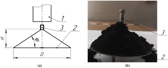
Figure 2.
Device for determining angle of natural slope: (a) diagram: 1—cylindrical funnel; 2—base, 3—rod; (b) photo: D—base diameter, mm; φ—angle of repose, degrees.
For the experiments, soil types typical of the region (Russian Federation, Republic of Bashkortostan) were selected: ordinary chernozem with sandy loam, light loam, medium loam, and heavy loam textures.
To determine the angle of repose, samples were collected from 3 to 5 randomly selected points along the diagonal of a field plot measuring 25 m2, at depths of 0.1, 0.2, and 0.3 m. The samples were taken using a cylindrical core sampler, with a cartridge diameter slightly greater than its height, which helps minimize deformation of the soil during sampling. At each depth, five replicate samples were collected. Sampling was performed without disturbing the natural soil structure, which allows for the determination of soil bulk density using the mass of the sample mmm, in kilograms, and the volume of the sampler V, in cubic meters, according to the following formula:
To determine soil moisture, the collected samples were thoroughly mixed into a composite sample weighing approximately 1 kg. Soil moisture content was measured using the accelerated drying method: samples were placed in aluminum cups and dried in a SNOL 67/350 drying oven at 105 °C for 4 h, followed by an additional drying period of 1 h. The soil moisture W, expressed as a percentage, was calculated using the following formula:
where a is the mass of the empty cup, g; b is the mass of the cup with wet soil, g; c is the mass of the cup with completely dry soil, g.
The simulation of the discrete media pouring process, using a device with geometric parameters matching the experimental setup, was performed with the Rocky DEM software package. Rocky DEM is a contemporary software tool that enables the modeling of particles with various geometric shapes, allowing for more realistic results. A solid 3D model of the angle of repose measurement device was created for the simulation based on its actual dimensions (Figure 3a). To accurately replicate the experiment, the volumetric feed rate of soil particles, the time required to fill the cylindrical funnel, and the time to initiate funnel lifting were pre-calculated. The funnel was filled with soil particles 5 mm in diameter. The simulation was conducted at full scale. The funnel’s geometric dimensions matched those of the actual device. The speed of funnel lifting is critical; following recommendations by Barr J. et al. [9] and Ucgul M. et al. [12], the funnel should be lifted slowly and without acceleration. In the simulation, the funnel lifting speed was set at 0.1 m/s. Figure 3 illustrates the formation of the soil particle cone from funnel discharge and the measurement of the angle of repose in Rocky DEM software.
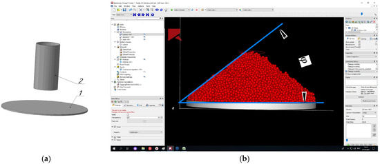
Figure 3.
Measuring the angle of natural repose. (a) A 3D model of the cylindrical funnel and the plane; (b) measurement of the angle of repose.
The main parameters of the studied contact models were selected based on a previous study [50] and are presented in Table 3.
Table 3.
Parameters of contact models.
3. Research Results
Table 4 presents the results of tests carried out to determine the angle of repose for different types of soils at different moisture contents.
Table 4.
Angle of repose depending on soil type and moisture content (n—range of angle of repose values, Mm—mean value, σ—standard deviation).
The angle of repose varied from 15.1° to 58.8°, with lower values observed for sandy loam soils and higher values for heavy loams, attributed to their clay content. The average angle of repose values obtained from simulations using 17 contact models (Table 2) are presented in Table 5.
Table 5.
Angle of natural slope of various combinations of contact models.
Comparison of the simulation results of discrete particle scattering and heap formation on a round base for different soil types produced the following contact models (Table 5):
- 1.1.1. Linear Spring Model (Normal Forces)—Linear Spring Limit Model (Tangential Forces)—Constant Adhesion Force Model;
- 1.1.2. Linear Spring Model (Normal Forces)—Linear Spring Limit Model (Tangential Forces)—Linear Adhesion Force Model;
- 1.2.1. Linear Spring Model (Normal Forces)—Coulomb Limit Model—Constant Adhesion Force Model;
- 2.1.1. Hysteresis Linear Spring Model (Normal Forces)—Linear Spring Limit Model (Tangential Forces)—Constant Adhesion Force Model;
- 2.2.1. Hysteresis Linear Spring Model (Normal Forces)—Coulomb Limit Model (Tangential Forces)—Constant Adhesion Force Model;
- 3.1.1. Hertz Model (Normal Forces)—Linear Spring Limit Model (Tangential Forces)—Constant Adhesion Force Model;
- 3.2.1. Hertz Model (Normal Forces)—Coulomb Limit Model (Tangential Forces)—Constant Adhesion Force Model;
- 3.3.1. Hertz Model (Normal Forces)—Mindlin–Deresiewicz Model (Tangential Forces)—Constant Adhesion Force Model.
These models failed to form cones with inclination angles corresponding to the natural repose angles (φvn) of the studied soils (Table 4). The angles of repose of the model particles did not exceed 12.8° in these cases. Thus, these models are unsuitable for simulating ordinary chernozem soils (heavy loam, light loam, sandy loam) using the DEM.
The Constant Adhesion Force Model was found to be incompatible with all normal/tangential force models, as no combination produced adequate repose angles.
An assessment of the suitability of contact models based on the angle of repose showed that the combination of models 1.2.2 is suitable for modeling sandy loam soils, the combination of models 3.1.2 is suitable for light loam, the combination of models 2.1.2, 2.2.2, 3.1.3, 3.2.2, 3.2.3, and 3.3.2 is suitable for medium loamy soils, and the combination of models 3.2.3 and 3.3.3 is suitable for heavy loam soils. Generalized data with suitable combinations of contact models for the studied soil types and moisture levels are presented in Table 6.
Table 6.
Suitable combinations of contact models depending on soil type and moisture content.
For the studied soils, nine combinations of contact models implemented in Rocky DEM are suitable for discrete element method simulations (the HSD–Coulomb–JKR combination applies to both medium and heavy loam). For medium and heavy soils with increased moisture up to 31%, the most suitable combinations are normal and tangential force models combined with the JKR cohesion model.
Based on this analysis, nine combinations of discrete element method contact models implemented in Rocky DEM are appropriate for modeling technological processes of soil tillage for sandy loam, light loam, medium loam, and sandy mechanical compositions.
4. Conclusions
The discrete element method (DEM) has proven effective in modeling soil–tool interactions. However, its adoption in engineering practice remains limited due to challenges related to contact model selection, prediction accuracy, and computational demands for realistic particle sizes and shapes.
This study systematized DEM contact models into three categories:
- Normal interaction: linear spring model, hysteresis model, and Hertz–Mindlin model;
- Tangential interaction: Coulomb model, linear spring limit model, and Mindlin–Deresiewicz model;
- Cohesion/adhesion: Linear cohesion model, Parallel Bonds Model, JKR model, and Edinburgh Elastic–Plastic Adhesion (EEPA) Model.
Considering the incompatibility of some models with each other, 17 combinations of contact models implemented in the commercial software Rocky DEM are available for modeling soil tillage processes using the discrete element method. These include three categories: normal force models (linear spring (LSP), hysteresis (HLS), Hertz (HSD)), tangential force models (Coulomb, linear spring limit (linear), Mindlin–Deresiewicz), and cohesion force models (linear cohesion (linear), constant force (constant), Johnson–Kendall–Roberts (JKR)).
Experimental validation of the models based on the analysis of the angle of repose for different soil types (sandy loam, light loam, medium loam, and heavy clay soils) at various moisture contents (11–31%) identified the nine most effective combinations of contact models for normal forces, tangential forces, and cohesion forces (LSP–Coulomb–linear, HLS–linear–linear, HLS–Coulomb–linear, HSD–linear–linear, HSD–linear–JKR, HSD–Coulomb–linear, HSD–Coulomb–JKR, HSD–Mindlin–Deresiewicz–linear, HSD–Mindlin–Deresiewicz–JKR), which provide a reliable fit for the angle of repose with an accuracy of 85%.
For medium and heavy soils with moisture up to 31%, combinations of normal and tangential force models with the JKR cohesion model are suitable. Models that include a constant cohesion force are unsuitable for modeling as they do not reproduce the expected angles of repose.
The developed classification and recommendations for selecting contact models will improve the accuracy of discrete element method modeling in the design of soil tillage machinery. The obtained data can be used to calibrate DEM parameters considering soil type and moisture content. The results open prospects for further research, including the modeling of traction resistance and optimization of agricultural machinery working tools.
Author Contributions
Conceptualization, S.M.; methodology, S.M. and L.K.; investigation, I.F.; resources, I.G.; writing—original draft preparation, S.M.; writing—review and editing, Y.L. and L.K.; visualization, I.F.; project administration, I.G. All authors have read and agreed to the published version of the manuscript.
Funding
This research was funded by the Russian Science Foundation, grant No. 23-76-10070 (https://rscf.ru/project/23-76-10070/, accessed on 10 February 2023).
Data Availability Statement
The original contributions presented in this study are included in the article. Further inquiries can be directed to the corresponding author.
Acknowledgments
The research was carried out with funding via the grant of the Russian Science Foundation No. 23-76-10070 (https://rscf.ru/project/23-76-10070/, accessed on 10 February 2023).
Conflicts of Interest
The authors declare no conflicts of interest.
References
- Mudarisov, S.; Farkhutdinov, I.; Mukhametdinov, A.; Aminov, R.; Bagautdinov, R.; Gallyamov, F. Evaluation of loosening and soil compaction with a working tool of tillage machines using a hydrodynamic model. Int. Rev. Model. Simul. 2020, 13, 394–399. [Google Scholar] [CrossRef]
- Cundall, P.A.; Strack, O.D.L. A discrete numerical model for granular assembles. Géotechnique 1979, 29, 47–65. [Google Scholar] [CrossRef]
- Zhao, H.; Huang, Y.; Liu, Z.; Liu, W.; Zheng, Z. Applications of discrete element method in the research of agricultural machinery: A review. Agriculture 2021, 11, 425. [Google Scholar] [CrossRef]
- Tanaka, H.; Oida, A.; Daikoku, M.; Inooku, K.; Sumikawa, O.; Nagasaki, Y.; Miyazaki, M. DEM Simulation of Soil Loosening Process Caused by a Vibrating Subsoiler. Agric. Eng. Int. CIGR Ejournal 2007, 9, 1–18. Available online: https://ecommons.cornell.edu/server/api/core/bitstreams/b91ccb60-3616-41f8-83f9-2e2a2919fdbe/content (accessed on 10 February 2023).
- Tanaka, H.; Momozu, M.; Oida, A.; Yamazaki, M. Simulation of soil deformation and resistance at bar penetration by the distinct element method. J. Terramech. 2000, 37, 41–56. [Google Scholar] [CrossRef]
- Asaf, Z.; Rubinstein, D.; Shmulevich, I. Determination of discrete element model parameters required for soil tillage. Soil Tillage Res. 2007, 92, 227–242. [Google Scholar] [CrossRef]
- Ono, I.; Nakashima, H.; Shimizu, H.; Miyasaka, J.; Ohdoi, K. Investigation of elemental shape for 3D DEM modeling of interaction between soil and a narrow cutting tool. J. Terramech. 2013, 50, 265–276. [Google Scholar] [CrossRef]
- Makange, N.R.; Ji, C.; Torotwa, I. Prediction of cutting forces and soil behavior with discrete element simulation. Comput. Electron. Agric. 2020, 179, 105848. [Google Scholar] [CrossRef]
- Barr, J.; Desbiolles, J.; Fielke, J.; Ucgul, M. Optimising bentleg opener geometry for high speed no-till seeding using DEM simulations. In Proceedings of the 21st ISTRO International Conference 2018, Paris, France, 21–24 September 2018; pp. 410–412. [Google Scholar]
- Barr, J.; Desbiolles, J.; Ucgul, M.; Fielke, J.M. Bentleg furrow opener performance analysis using the discrete element method. Biosyst. Eng. 2020, 189, 99–115. [Google Scholar] [CrossRef]
- Aikins, K.A.; Ucgul, M.; Barr, J.B.; Jensen, T.A.; Antille, D.L.; Desbiolles, J.M. Determination of discrete element model parameters for a cohesive soil and validation through narrow point opener performance analysis. Soil Tillage Res. 2021, 213, 105123. [Google Scholar] [CrossRef]
- Ucgul, M.; Saunders, C.; Fielke, J.M. Discrete element modelling of tillage forces and soil movement of a one-third scale mouldboard plough. Biosyst. Eng. 2017, 155, 44–54. [Google Scholar] [CrossRef]
- Shmulevich, I.; Asaf, Z.; Rubinstein, D. Interaction between soil and a wide cutting blade using the discrete element method. Soil Tillage Res. 2007, 97, 37–50. [Google Scholar] [CrossRef]
- Sun, J.; Wang, Y.; Ma, Y.; Tong, J.; Zhang, Z. DEM simulation of bionic subsoilers (tillage depth > 40 cm) with drag reduction and lower soil disturbance characteristics. Adv. Eng. Softw. 2018, 119, 30–37. [Google Scholar] [CrossRef]
- Ding, S.; Bai, L.; Yao, Y.; Yue, B.; Fu, Z.; Zheng, Z.; Huang, Y. Discrete element modelling (DEM) of fertilizer dual-banding with adjustable rates. Comput. Electron. Agric. 2018, 152, 32–39. [Google Scholar] [CrossRef]
- Chen, Y.; Munkholm, L.J.; Nyord, T. A discrete element model for soil–sweep interaction in three different soils. Soil Tillage Res. 2013, 126, 34–41. [Google Scholar] [CrossRef]
- Tamás, K.; Jóri, I.J.; Mouazen, A.M. Modelling soil–sweep interaction with discrete element method. Soil Tillage Res. 2013, 134, 223–231. [Google Scholar] [CrossRef]
- Cheng, J.; Zheng, K.; Xia, J.; Liu, G.; Jiang, L.; Li, D. Analysis of adhesion between wet clay soil and rotary tillage part in paddy field based on discrete element method. Processes 2021, 9, 845. [Google Scholar] [CrossRef]
- Yang, Y.; Wen, B.; Ding, L.; Li, L.; Chen, X.; Li, J. Soil particle modeling and parameter calibration for use with discrete element method. Trans. ASABE 2021, 64, 2011–2023. [Google Scholar] [CrossRef]
- Hoseinian, S.H.; Hemmat, A.; Esehaghbeygi, A.; Shahgoli, G.; Baghbanan, A. Development of a dual sideway-share subsurface tillage implement: Part 1. Modeling tool interaction with soil using DEM. Soil Tillage Res. 2022, 215, 105201. [Google Scholar] [CrossRef]
- Dai, F.; Song, X.F.; Zhao, W.; Shi, R.J.; Zhang, F.; Zhang, X.K. Mechanism analysis and performance improvement of mechanized ridge forming of whole plastic film mulched double ridges. Int. J. Agric. Biol. Eng. 2020, 13, 107–116. [Google Scholar] [CrossRef]
- Hoseinian, S.H.; Hemmat, A.; Esehaghbeygi, A.; Shahgoli, G.; Baghbanan, A. Development of a dual sideway-share subsurface tillage implement: Part 2. Effect of tool geometry on tillage forces and soil disturbance characteristics. Soil Tillage Res. 2022, 215, 105200. [Google Scholar] [CrossRef]
- Bo, L.; Rui, X.; Fanyi, L.; Jun, C.; Wenting, H.; Bing, H. Determination of the draft force for different subsoiler points using discrete element method. Int. J. Agric. Biol. Eng. 2016, 9, 81–87. [Google Scholar]
- Tamás, K.; Kovács, Á.; Jóri, I.J. The evaluation of the parallel bond’s properties in DEM modeling of soils. Period. Polytech. Mech. Eng. 2016, 60, 21–31. [Google Scholar] [CrossRef][Green Version]
- Tekeste, M.Z.; Balvanz, L.R.; Hatfield, J.L.; Ghorbani, S. Discrete element modeling of cultivator sweep-to-soil interaction: Worn and hardened edges effects on soil-tool forces and soil flow. J. Terramech. 2019, 82, 1–11. [Google Scholar] [CrossRef]
- Bo, L.; Fanyi, L.; Junying, M.; Jun, C.; Wenting, H. Distinct element method analysis and field experiment of soil resistance applied on the subsoiler. Int. J. Agric. Biol. Eng. 2014, 7, 54–59. [Google Scholar]
- Mak, J.; Chen, Y.; Sadek, M.A. Determining parameters of a discrete element model for soil–tool interaction. Soil Tillage Res. 2012, 118, 117–122. [Google Scholar] [CrossRef]
- Sadek, M.A.; Chen, Y.; Liu, J. Simulating shear behavior of a sandy soil under different soil conditions. J. Terramech. 2011, 48, 451–458. [Google Scholar] [CrossRef]
- Du, J.; Heng, Y.; Zheng, K.; Luo, C.; Zhu, Y.; Zhang, J.; Xia, J. Investigation of the burial and mixing performance of a rotary tiller using discrete element method. Soil Tillage Res. 2022, 220, 105349. [Google Scholar] [CrossRef]
- Zhai, S.; Shi, Y.; Zhou, J.; Liu, J.; Huang, D.; Zou, A.; Jiang, P. Simulation optimization and experimental study of the working performance of a vertical rotary tiller based on the discrete element method. Actuators 2022, 11, 342. [Google Scholar] [CrossRef]
- Yang, L.; Li, J.; Lai, Q.; Zhao, L.; Li, J.; Zeng, R.; Zhang, Z. Discrete element contact model and parameter calibration for clayey soil particles in the Southwest hill and mountain region. J. Terramech. 2024, 111, 73–87. [Google Scholar] [CrossRef]
- Chen, Z.; Duan, A.; Liu, Y.; Zhao, H.; Dai, C.; Hu, S.; Lei, X.; Hu, J.; Chen, L. Discrete element contact model and parameter calibration of sticky particles and agglomerates. J. Terramech. 2024, 116, 100998. [Google Scholar] [CrossRef]
- Kim, Y.S.; Siddique, M.A.A.; Kim, W.-S.; Kim, Y.-J.; Lee, S.-D.; Lee, D.-K.; Hwang, S.-J.; Nam, J.-S.; Park, S.-U.; Lim, R.-G. DEM simulation for draft force prediction of moldboard plow according to the tillage depth in cohesive soil. Comput. Electron. Agric. 2021, 189, 106368. [Google Scholar] [CrossRef]
- Wu, Z.; Wang, X.; Liu, D.; Xie, F.; Ashwehmbom, L.G.; Zhang, Z.; Tang, Q. Calibration of discrete element parameters and experimental verification for modelling subsurface soils. Biosyst. Eng. 2021, 212, 215–227. [Google Scholar] [CrossRef]
- Zhao, Z.; Li, H.; Liu, J.; Yang, S.X. Control method of seedbed compactness based on fragment soil compaction dynamic characteristics. Soil Tillage Res. 2020, 198, 104551. [Google Scholar] [CrossRef]
- Ucgul, M.; Fielke, J.M.; Saunders, C. Defining the effect of sweep tillage tool cutting edge geometry on tillage forces using 3D discrete element modelling. Inf. Process. Agric. 2015, 2, 130–141. [Google Scholar] [CrossRef]
- Ucgul, M.; Fielke, J.M.; Saunders, C. Three-dimensional discrete element modelling (DEM) of tillage: Accounting for soil cohesion and adhesion. Biosyst. Eng. 2015, 129, 298–306. [Google Scholar] [CrossRef]
- DEM Technical Manual. Version 2023 R2. Available online: https://ansyshelp.ansys.com/public/account/secured?returnurl=/Views/Secured/corp/v242/en/dem_tec/dem_tec.html (accessed on 30 January 2025).
- Walton, O.R.; Braun, R.L. Stress calculations for assemblies of inelastic spheres in uniform shear. Acta Mech. 1986, 63, 73–86. [Google Scholar] [CrossRef]
- Aikins, K.A.; Ucgul, M.; Barr, J.B.; Awuah, E.; Antille, D.L.; Jensen, T.A.; Desbiolles, J.M. Review of discrete element method simulations of soil tillage and furrow opening. Agriculture 2023, 13, 541. [Google Scholar] [CrossRef]
- Tamas, K.; Bernon, L. Role of particle shape and plant roots in the discrete element model of soil–sweep interaction. Biosyst. Eng. 2021, 211, 77–96. [Google Scholar] [CrossRef]
- Obermayr, M.; Vrettos, C.; Eberhard, P. A discrete element model for cohesive soil. In Proceedings of the III International Conference on Particle-based Methods—Fundamentals and Applications, PARTICLES 2013, Stuttgart, Germany, 18–20 September 2013; pp. 783–794. [Google Scholar]
- Potyondy, D.O.; Cundall, P.A. A bonded-particle model for rock. Int. J. Rock Mech. Min. Sci. 2004, 41, 1329–1364. [Google Scholar] [CrossRef]
- Wang, X.; Zhang, Q.; Huang, Y.; Ji, J. An efficient method for determining DEM parameters of a loose cohesive soil modelled using hysteretic spring and linear cohesion contact models. Biosyst. Eng. 2022, 215, 283–294. [Google Scholar] [CrossRef]
- Van der Linde, J. Discrete Element Modeling of a Vibratory Subsoiler. Ph.D. Thesis, University of Stellenbosch, Stellenbosch, South Africa, 2007. [Google Scholar]
- Milkevych, V.; Munkholm, L.J.; Chen, Y.; Nyord, T. Modelling approach for soil displacement in tillage using discrete element method. Soil Tillage Res. 2018, 183, 60–71. [Google Scholar] [CrossRef]
- Johnson, K.L.; Kendall, K.; Roberts, A.A.D. Surface energy and the contact of elastic solids. Proc. R. Soc. A Math. Phys. Eng. Sci. 1971, 324, 301–313. [Google Scholar] [CrossRef]
- Zhang, C.; Xu, J.; Zheng, Z.; Wang, W.; Liu, L.; Chen, L. Three-dimensional DEM tillage simulation: Validation of a suitable contact model for a sweep tool operating in cohesion and adhesion soil. J. Terramech. 2023, 108, 59–67. [Google Scholar] [CrossRef]
- Thakur, S.C.; Morrissey, J.P.; Sun, J.; Chen, J.F.; Ooi, J.Y. Micromechanical analysis of cohesive granular materials using the discrete element method with an adhesive elasto-plastic contact model. Granul. Matter 2014, 16, 383–400. [Google Scholar] [CrossRef]
- Mudarisov, S.; Farkhutdinov, I.; Khamaletdinov, R.; Khasanov, E.; Mukhametdinov, A. Evaluation of the significance of the contact model particle parameters in the modelling of wet soils by the discrete element method. Soil Tillage Res. 2022, 215, 105228. [Google Scholar] [CrossRef]
Disclaimer/Publisher’s Note: The statements, opinions and data contained in all publications are solely those of the individual author(s) and contributor(s) and not of MDPI and/or the editor(s). MDPI and/or the editor(s) disclaim responsibility for any injury to people or property resulting from any ideas, methods, instructions or products referred to in the content. |
© 2025 by the authors. Licensee MDPI, Basel, Switzerland. This article is an open access article distributed under the terms and conditions of the Creative Commons Attribution (CC BY) license (https://creativecommons.org/licenses/by/4.0/).