Article

Design and Experiment of Automatic Fish Bleeding Machine

1
Guangdong Institute of Modern Agricultural Equipment, Guangzhou 510630, China
2
Key Laboratory of Modern Agricultural Intelligent Equipment in South China, Ministry of Agriculture and Rural Affairs of the People’s Republic of China, Guangzhou 510630, China
*
Author to whom correspondence should be addressed.
AgriEngineering 2025, 7(4), 91; https://doi.org/10.3390/agriengineering7040091
Submission received: 6 February 2025 / Revised: 5 March 2025 / Accepted: 19 March 2025 / Published: 21 March 2025

Abstract

:
Bleeding constitutes an essential stage in pre-processing operations for fish products. In China, this process remains entirely manual, characterized by low efficiency, high labor intensity, and operational hazards, creating a pressing demand for versatile automated equipment in the market. To address the mechanization requirements for efficient freshwater fish bloodletting, we developed an automated fish bleeding machine based on gill-based blood extraction principles, incorporating an impact-triggered positional bleeding methodology. The positional triggering mechanism was engineered through kinematic and dynamic analyses of fish sliding trajectories onto the trigger plate, informed by morphological parameters of fish specimens. This design achieved automated positional awareness and bleeding activation. A reciprocating bleeding mechanism was developed by mimicking manual bleeding motions, leveraging the quick-return motion characteristics of an offset crank-slider mechanism. The transmission system combined chain-drive and clutch mechanisms to enable sequential and intermittent power delivery. Experimental validation employed live specimens of snakehead (Channa argus), grass carp (Ctenopharyngodon idellus), and tilapia (Oreochromis mossambicus), with systematic evaluations including sensory assessments, comparative testing, and performance metrics. Results demonstrated a comprehensive sensory evaluation score of 3.8 for bleeding efficacy; significant influence of baffle geometry on performance, identifying V-shaped baffles as optimal; a bleeding success rate averaging 94% with throughput reaching 1417 fish/hour. The integrated workflow—directional feeding, postural constraint, positional triggering, reciprocating bleeding, and automated ejection—established a cyclic mechanized bleeding process with industrial applicability.

1. Introduction

China is a major aquaculture country. In 2023, the total output of aquatic products in China reached 71.1617 million tons, of which the total amount of aquatic products for processing was 26.2371 million tons [1]. The manual processing mode can no longer meet the requirements of large-scale production. High-quality, efficient, and mechanized aquatic product processing has become an inevitable requirement. At present, the degree of manual participation in the pre-processing procedures of aquatic product processing in China is relatively high. The overall technology is weak, and the degree of mechanization is not high. It still relies on manual labor in key links and belongs to a labor-intensive industry [2,3,4]. Therefore, the development of key technical equipment for the pre-processing of aquatic products has important practical significance.
The pre-processing procedures of fish include grading, bleeding, descaling, decapitation, cutting, evisceration, skinning, slicing, and other links [5,6,7]. Bleeding fish is a key step in the pre-processing of fish. A major cause of downgrading and rejection of fish in the white fish industry is due to discoloration of the fillets because of poor exsanguination. By studying the effects of different bleeding methods on the blood residuals and color of fish meat, it can be seen that bleeding can reduce the blood residuals and improve the fillet whiteness. The various bleeding methods do not demonstrate a clear impact trend on fillet quality [8]. Muscle activity during the bleeding process is considered less crucial for achieving effective exsanguination [9]. Myoglobin and hemoglobin, the primary pigment components in fish flesh, constitute key factors influencing meat coloration. Under thorough bleeding conditions, myoglobin accounts for 80–90% of total pigments. During fillet processing, untreated blood can lead to hemoglobin residues remaining in muscle tissues, thereby reducing meat brightness (L* value) and darkening flesh coloration. Consequently, hemoglobin retention induces discoloration, whereas proper bleeding enables fillets to exhibit a whiter appearance [10]. Fish blood contains odorous compounds, and blood residues contribute to undesirable fishy odors during cooking. Fish flesh after bleeding has a less fishy smell, which is conducive to improving the taste and quality of fish flesh. Simultaneously, exsanguination decreases the accumulation of blood metabolites (e.g., lactic acid), retards spoilage processes, and proves particularly critical for raw consumption products like sashimi. Effective bleeding alleviates blood coagulation-induced compression on muscle fibers, resulting in firmer texture and improved processing resistance. When combined with low-temperature treatment, bled fish flesh exhibits significantly extended shelf life. Therefore, bleeding treatment maintains flesh coloration, reduces fishy odors, enhances product quality, and facilitates subsequent storage and processing operations.
The gill bleeding process of fish is as follows: generally, a cut is made under the edge of both gill covers, and then the fish is placed in clean water to swim freely. During the free swimming of the fish, the blood inside the body will accelerate its flow out of the body, minimizing the residual blood volume within the fish. The arterial system of fish originates from the ventral aorta in front of the heart, extending forward to below the gill arches, giving off several pairs of arteries that enter the gill arches. After entering the gills, these arteries branch into capillaries, which enter the gill filaments and gill lamellae for gas exchange. The arterial blood from the gills converges into the efferent gill arteries, which then ascend through the dorsal aorta and branch into the dorsal aorta in the back [11]. Therefore, the gill area is a location with a concentrated distribution of blood vessels, having a rich supply of arteries, and bleeding at the gills can achieve a better bleeding effect. Taking the snakehead slices commonly used as raw materials for dishes such as pickled fish and boiled fish as an example, bleeding is the first process link in the production of snakehead slices. Currently, the processing volume of finished snakehead slices in China is about 500,000 tons, which basically relies on manual bleeding, and the market demand for mechanized bleeding is huge. The development of fish bleeding equipment abroad is relatively mature. The FS-320 type fish killing and bleeding machine developed by Japan’s Morimatsu Fisheries Company [12] realizes rapid fish killing and bleeding by piercing the gill part of the fish body with a needle-like mechanism. The structure is simple and reliable, and its processing capacity can reach 1200 pieces per hour. This machine has requirements for the feeding posture of the material, and it needs manual head–tail directional feeding of the fish body. Germany’s BAADER Company has developed swimming-in automatic fish killing and bleeding equipment [13], with a processing capacity of up to 2880 pieces per hour. It adopts four-channel parallel operation and guides live fish to swim into the bleeding channel automatically, realizing fully automated directional feeding and bleeding operations. The bleeding equipment developed abroad is mainly targeted at larger-sized marine fish, such as yellowtail, cod, salmon, etc., with a specification of at least 3.5 kg and above, which is difficult to adapt to the use scenario of small-sized freshwater fish in China. The research on fish processing in China mainly focuses on directional, descaling, decapitation, evisceration, skinning, and other links [14,15,16,17,18,19,20]. So far, there have been no reports on fish bleeding technical equipment. The bleeding link in China completely relies on manual knife bleeding treatment, and the fish killing and bleeding method also depends on the experience of workers, without forming a standardized operation process. This processing method is inefficient, labor-intensive, and somewhat dangerous. Therefore, the fish killing and bleeding link in China is in a state of “no machine available,” and the market needs practical equipment with strong adaptability.
Aiming at the above problems, the key technology of automatic fish bleeding was studied, and the automatic fish bleeding machine was developed to realize the mechanization and automation of fish bleeding. It is expected to reduce the cost of aquatic product processing and meat loss, improve the mechanization level of pre-processing of aquatic products, and promote the high-quality and efficient development of the aquatic product processing industry.

2. Materials and Methods

2.1. Overall Structure

Aiming at the pre-processing requirements of spindle-shaped freshwater fish, with common freshwater fish such as snakehead and grass carp as research objects, an automatic fish bleeding machine is designed. It mainly consists of a fish entrance passage, a pre-channel adjustment mechanism, a bleeding mechanism, a post-channel adjustment mechanism, a transmission mechanism, a trigger mechanism, a motor, and a frame, as shown in Figure 1. Considering that this bleeding machine is designed for fish processing, all mechanical components are constructed from food-grade stainless steel (material specification: S30408) to ensure compliance with food safety requirements.

2.2. Working Principle

Based on the gill bleeding process in manual fish killing and combined with the external characteristics of fish, an impact-triggered limited bleeding method is proposed, as shown in Figure 2. The line segment ab is an inclined plane, and bod forms a rigid limiting trigger mechanism, with o as the pivot. The bleeding knife, connecting rod, and cam constitute a crank-slider mechanism. The implementation process of this method is as follows: The fish slides down from point a to point b with its head facing forward. Utilizing the characteristic that the gravitational potential energy of the fish is converted into kinetic energy during the sliding process, the fish impacts point b, triggering the rotation of bod to b’od’. Under the resistance of the bod mechanism, the fish is ultimately limited to point b’. At this time, the cam releases the limit and begins to rotate in a clockwise direction. Under the action of the crank connecting rod mechanism, the bleeding knife makes a reciprocating kinematics in the direction of the dashed line, achieving the action of piercing the gills and then resetting. Subsequently, the inclined plane ab rotates counterclockwise around point a by a certain angle, releasing the fish from the limit at point b and allowing it to continue sliding down, thus discharging the bled fish. After the fish is discharged, b’od’ returns to bod, and the cam, after completing one full rotation, is limited by od and stops rotating, completing one bleeding cycle.
The fish bleeding device is designed based on the impact-triggered limited bleeding method. The specific working process is as follows: Before the device is started, the working parameters of the bleeding device are adjusted according to the fish size. The position of the adjustment handle is manually adjusted to make the cutting position and the size of the feeding port suitable for the current fish size. Then, the motor is started and the transmission mechanism is in a locked state. The fish is fed into the fish entrance passage with its head facing forward. The fish slides along the channel-supporting plate to the front end. The channel-supporting plate and the pre-channel adjustment plate constrain the fish head and body, and the positioning blade applies adaptive pressure to the fish body to keep the front and rear positions of the fish fixed. Under the action of the sliding kinetic energy of the fish, the fish head pushes the bleeding trigger mechanism to move, releasing the locked state of the transmission mechanism and initiating the bleeding action. Under the driving force of the motor, the crank-slider mechanism begins to move. The blade slides down, inserts into the gills, and then moves upward to reset. Then, the channel-supporting plate rotates downward, the front end outlet of the fish entrance passage opens, the fish body constraint is released, and the fish slides out from the outlet and enters the bleeding pool. Subsequently, driven by the transmission mechanism, the channel-supporting plate rotates back to its original position. After the transmission mechanism completes one working cycle, it returns to the locked state, waiting for the next bleeding action to start.

2.3. Technical Parameters

The current manual bleeding operation efficiency is generally about 1000 pieces per hour. Considering that one bleeding machine can at least replace one skilled worker, the working efficiency of the bleeding machine needs to be no less than 1000 pieces per hour. The main design parameters of the machine are shown in Table 1.

2.4. Fish Body Shape Feature Parameters

Based on the commonly used fish species in freshwater fish processing enterprises, spindle-shaped fish such as snakehead (Channa argus), grass carp (Ctenopharyngodon idellus), silver carp (Hypophthalmichthys molitrix), and tilapia (Oreochromis mossambicus) are selected as the research objects. The external structure of the fish body is shown in Figure 3, which is mainly divided into three parts: the head, the trunk, and the tail. D1 is the total length of the fish body along the head–tail axis, D2 is the length of the head, and D3 is the maximum height of the fish head along the ventral–dorsal axis [21].
According to the actual needs of freshwater fish processing, the commonly used fish size range is between 250 g and 2500 g. Thirty fish of each species were randomly selected as measurement samples. In accordance with the design requirements of the fish bleeding device, the fish head is the key part for bleeding operations. Therefore, the main measurements include the fish body weight, the total length of the fish body along the head–tail axis, the length of the head, the maximum height of the fish head along the ventral–dorsal axis, the maximum width of the fish head along the left–right axis, and the sliding friction angle between the fish body and 304 stainless steel plate. The results of the main body shape measurement parameters of fish are shown in Table 2.

2.5. Design of Fish Entrance Passage

The fish entrance passage is the main component that supports and constrains the fish body, enabling the fish to slide in and be supported, thus creating stable conditions for the bleeding action. The fish entrance passage is inclined and mounted on the frame, mainly consisting of the feeding port, upper channel plate, channel-supporting plate, channel side plates, and the front channel arc plate, as shown in Figure 4. The channel-supporting plate, channel side plates, and front channel arc plate together form a space that envelops the fish head, which is conducive to the stable constraint of the fish body. Based on the measurement data of the sliding friction angle of fish, the angle between the upper channel plate of the fish entrance passage and the horizontal direction is determined to be 30°, which is considered appropriate.
The channel-supporting plate is the main contact component for the fish to slide down, and its structure directly affects the stability of the fish body support during the bleeding process. The channel-supporting plate includes a support plate, side wing plates, a supporting plate, and hinges. The schematic diagram of the channel-supporting plate supporting the fish head is shown in Figure 5. The channel-supporting plate is designed based on the external contour of the fish head, with the support plate achieving a fit and support for the fish head, and two symmetrical side wing plates supporting the sides of the fish body. When the channel-supporting plate rotates downward, the fish inlet channel opens, allowing the fish being bled to slide out from the channel.
Analysis of the head shape characteristics of three types of spindle-shaped fish shows that the fish head can be approximated as an elliptical cone. Combining the measurement parameters of the fish head’s external dimensions, it can be determined that within the measured fish size range, the fish head is located within an enveloping space of an elliptical cone. The model parameters of this elliptical cone are a base long axis of 120 mm, a base short axis of 70 mm, and a height of 158 mm. Based on the schematic diagram of the channel-supporting plate supporting the fish head shown in Figure 5, the support plate is designed according to the elliptical cone fish head enveloping model. The spatial coordinate schematic diagram of the support plate is shown in Figure 6.
Based on the elliptical cone fish head enveloping model, according to the effective length parameter of the fish head, a height of 125 mm of the elliptical cone is taken as the design parameter for the contour of the support plate. Therefore, the external contour of the support plate is obtained as the curved surface abcd, and the equation of this curved surface model is as follows:
6241 x 2 900 z 2 + 24964 y 2 1225 z 2 = 1 . ( 0 y 35 , 33 z 158 )

2.6. Design of Bleeding Mechanism

The bleeding mechanism mainly consists of a knife holder, knife holder guide rails, connecting rods, and a drive wheel mechanism, as shown in Figure 7. The working principle of the bleeding mechanism is to imitate the action of manual fish killing and bleeding, achieving bleeding at the gill area of the fish. The specific working process is as follows: when the fish reaches the channel-supporting plate, the bleeding knife quickly descends to pierce the gills, cutting the arterial blood vessels in the gills, and then the bleeding knife ascends to reset. Therefore, the bleeding knife has the characteristic of reciprocating kinematics. According to the working characteristics of the bleeding mechanism, a design with an offset crank-slider mechanism that has a quick-return kinematic characteristic is adopted. The descent direction of the bleeding knife is made consistent with the quick-return kinematic direction of the mechanism, which is beneficial for the bleeding knife to quickly pierce the fish body when the fish slides down to the predetermined position.

2.6.1. Kinematic Analysis

The kinematic of the bleeding mechanism follows the kinematic characteristics of the offset crank-slider mechanism. Through structural simplification, the kinematic schematic diagram of the bleeding mechanism is obtained as shown in Figure 8. AB is the crank, BC is the connecting rod, B1 and B2 are the left and right limit positions of point B when the mechanism is in the limit state, and C1 and C2 are the left and right limit positions of point C when the mechanism is in the limit state [22].
From Figure 9, it can be seen that the positional relationship of the bleeding mechanism needs to satisfy the following equation:
r m i n = cos 1 ( a + e b ) H s i n θ = a + b e / ( b a ) H 2 = ( b a ) 2 + ( b + a ) 2 2 ( b a ) ( b + a ) c o s θ θ = 180 ° ( K 1 ) K + 1 a + e b
According to the overall structure and operational requirements of the bleeding machine, the stroke velocity ratio coefficient of the bleeding mechanism is determined to be K = 1.06, and the stroke of the knife holder is H = 145 mm. Based on the positional relationship between the drive wheel mechanism and the knife holder, the length of the connecting rod b is preliminarily determined to be no less than 500 mm. The crank-slider mechanism often uses the size of rmin to measure the power transmission performance of the mechanism; the larger the rmin, the more favorable it is for transmission [23,24,25]. Therefore, with rmin as the optimization target, the final determination is a = 68 mm, b = 554 mm, at which time rmin = 62.2°.

2.6.2. Bleeding Knife

The bleeding knife is the core component of the bleeding mechanism. The bleeding knife is designed with a wedge-shaped structure, with two blades arranged in a V-shape below the knife holder, as shown in Figure 9. Based on the shape of the fish head and the distribution of the gills, the angle between the two blades is determined to be 160°, and the width of the blade is 40 mm. This design of the bleeding knife structure and position is conducive to the blades piercing into the gill area of the fish body, obtaining an appropriate bleeding opening.

2.7. Design of Transmission Mechanism

The transmission requirements of the bleeding machine mainly come from the reciprocating motion of the bleeding mechanism and the opening and closing motion of the channel-supporting plate. The bleeding operation process indicates that the bleeding mechanism moves first, and after the bleeding is completed, the channel-supporting plate performs the opening and closing motion. Without the next trigger start, both motion mechanisms stop moving after completing one action cycle. Therefore, the transmission of this machine has the characteristics of sequentiality and intermittence. To meet the transmission requirements, the transmission mechanism adopts a design combining chain transmission structure with a clutch mechanism. The structure of the transmission mechanism is shown in Figure 10, mainly consisting of a clutch assembly, bleeding drive wheel, transmission chain, channel-supporting plate drive wheel, tension wheel, driving wheel, transmission rod, and trigger rotating arm. When the bleeding mechanism’s positional lock is disengaged, the trigger rotating arm synchronizes its rotation with the clutch of the bleeding mechanism. After the trigger rotating arm rotates by a certain angle, it begins to contact the triangular-structured transmission rod. The transmission rod undergoes a slight clockwise rotation under force, thereby disengaging the limit of the corresponding clutch for the channel-supporting plate. Driven by the channel-supporting plate drive wheel, the channel-supporting plate initiates the opening–closing motion. The transmission phase difference between the bleeding mechanism and the channel-supporting plate is 225°.
Two limit clutch mechanisms are installed on the bleeding drive wheel and the channel-supporting plate drive wheel, respectively. The bleeding drive wheel can drive the main shaft of the bleeding mechanism to rotate through the limit clutch mechanism, and the channel-supporting plate drive wheel can drive the drive shaft of the channel-supporting plate to rotate through the limit clutch mechanism. The driving wheel is installed on the motor shaft and continuously transmits power through the chain. When the clutch assembly releases the limit and is in the engaged state, the shaft rotates synchronously with the sprocket, achieving the rotation of the main shaft of the bleeding mechanism and the drive shaft of the channel-supporting plate. When the clutch assembly reaches the limit position and is in the disengaged state, the sprocket rotates but the shaft does not move, realizing the disconnection of the transmission.
As shown in Figure 10, the bleeding drive wheel and the channel-supporting plate drive wheel are driven wheels. The transmission ratio i2 between the driving wheel and the bleeding drive wheel and i3 between the driving wheel and the channel-supporting plate drive wheel are mainly designed according to the operation efficiency of the bleeding machine. The relationship between the operation efficiency of the bleeding machine and the feeding sliding time of the fish and the movement time of the transmission mechanism satisfies Equation (3):
t z = t 0 + t 1 + t 2 + t 3 3600 t z δ l a b = 1 2 a 1 t 1 2 a 1 = g sin β μ g cos β t 2 = θ 2 / 6 n 2 t 3 = 360 / 6 n 3 n 2 = i 2 n 1 n 3 = i 3 n 1
where tz—the total time for the bleeding machine to perform a bleeding cycle, s;
t0—feeding redundancy time, s;
t1—the sliding time of fish on the channel-supporting plate, s;
t2—the time from the beginning of the bleeding mechanism to the beginning of the movement of the channel-supporting plate, s;
t3—the time for the channel-supporting plate drive wheel to rotate for one revolution, s;
δ —design parameters of working efficiency of bleeding machine, fish/hour;
μ —dynamic friction coefficient between fish and the channel-supporting plate;
lab—the distance from the vertex of the channel-supporting plate to the initial position of the trigger baffle plate, m;
a1—the acceleration of the fish sliding, m/s2;
β —the angle between the channel-supporting plate and the horizontal direction, °;
θ 2 —the transmission phase difference between the bleeding mechanism and the channel-supporting plate, °;
n1—speed of driving wheel, r/min;
n2—speed of bleeding drive wheel, r/min;
n3—speed of channel-supporting plate drive wheel, r/min.
According to the technical parameters and design requirements of the bleeding machine, δ is 1000 fish/hour, t0 is set as 1 s, and n1 is 90 r/min. Therefore, according to Equation (3), the relationship between i2 and i3 can satisfy
2 3 i 3 + 5 12 i 2 0.83
Therefore, combined with the design requirements of the chain transmission mechanism and the overall size of the transmission mechanism, i2 is finally determined to be 1.5 and i3 to be 2.

Clutch Assembly

The clutch assembly is the key to intermittent transmission and mainly consists of a return spring, a rotating sleeve, a cam roller frame, rollers, a passive star wheel, and an active hub, as shown in Figure 11. Eleven rollers are evenly nested in the cam roller frame and placed between the passive star wheel and the active hub, achieving power transmission from the active hub to the passive star wheel. The return spring connects the rotating sleeve and the cam roller frame, and the stretched return spring provides the torque for the cam roller frame to rotate back to its original position.
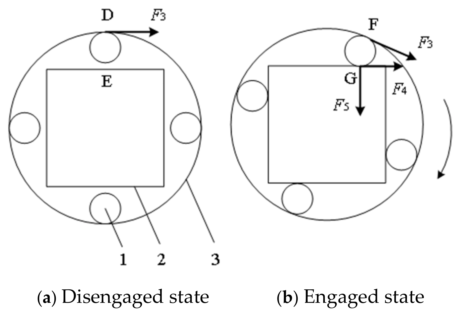
When the clutch assembly is in the limited position, its position state is shown in Figure 12a. Under the action of the limiting mechanism, the cam roller frame causes the rollers to be tangent to the active hub. Since the distance DE is greater than the diameter of the rollers, the rollers do not come into contact with the passive star wheel. Driven by the chain transmission mechanism, the active hub rotates uniformly in a clockwise direction. Due to the friction force F3 exerted by the active hub on the rollers, the rollers rotate on their own axis, while the passive star wheel remains stationary. Therefore, when the clutch assembly is in the disengaged state, the active hub rotates, but the passive star wheel does not.
After the limit on the cam roller frame is released, under the pull of the return spring, the rollers rotate clockwise with the cam roller frame. Since the distance between the active hub and the passive star wheel decreases in the clockwise direction, when the rollers move to point F, they begin to contact the passive star wheel at point G, as shown in Figure 12b. At this moment, the rollers start to exert pressure F5 and friction force F4 on the passive star wheel.
Analyzing Figure 12b, the total torque M of the passive star wheel can be obtained as follows:
M = n F 5 ( l E G + μ 1 l O E ) M 0
where n—the number of passive star wheel edges;
M0—the maximum resistance torque of the passive star wheel, N.m;
lEG—the distance between point E and point G, m;
lOE—the distance between point E and the center O of the passive star wheel, m;
μ1—the friction coefficient between the roller and the passive star wheel.
According to Equation (5), when M ≤ 0, the passive star wheel remains stationary. Under the drive of F3, the roller tends to rotate clockwise. Since the space between points F and G is the minimum space to accommodate the roller, the roller cannot continue to move. At this point, the active hub, roller, and passive star wheel are in a relatively stationary state. Due to the continuous torque output from the motor, F3 continues to increase, which in turn causes F5 to increase. As F5 increases, when M > 0, the passive star wheel overcomes the resistance and begins to rotate clockwise. When the rotational speed of the passive star wheel accelerates to match that of the active hub, the passive star wheel reaches a new torque balance and rotates synchronously with the active hub, and the clutch assembly enters the engaged state.

2.8. Design of Trigger Mechanism

2.8.1. Structure of Trigger Mechanism

The trigger mechanism is the switch that initiates the bleeding action of the bleeding mechanism. The trigger mechanism mainly consists of a trigger baffle plate, a trigger arm, a pillow block bearing, a trigger shaft, a spring, and a trigger rod, as shown in Figure 13. The working process of the trigger mechanism is as follows: The fish body, through the kinetic energy generated by sliding down, collides with the trigger baffle plate, causing the trigger rod to rotate a certain angle. The movement of the end of the trigger rod releases the cam from the limit and starts its rotation, driving the bleeding knife to move up and down reciprocally once. After the cam completes one full rotation, the trigger rod resets under the pull of the spring, limiting the cam from further rotation, thus completing the start–stop cycle.
To address the potential issue of trigger failure in automatic trigger mode, a manual trigger mechanism is added to the trigger mechanism, mainly consisting of a trigger link and a trigger handle, as shown in Figure 14. By rotating the trigger handle, the trigger rod is pushed to initiate the bleeding action, enhancing the reliability of the operation.

2.8.2. Mechanical Analysis

The simplified motion diagram of the trigger mechanism is shown in Figure 15. In the absence of a fish trigger, the trigger mechanism is in the bod position. The tension of the spring keeps the trigger rod at point d, where the trigger rod od is perpendicular to the straight edge de of the cam. The resistance force exerted by the trigger rod od on the cam can counteract the inertial force when the cam, in its counterclockwise rotation state, initially contacts the trigger rod, thus keeping the cam in a limited stop state.
In the state without fish triggering, to prevent the initial trigger torque from being too small and causing accidental triggering, an initial trigger torque constant C is introduced. At this time, the trigger mechanism is in a torque balance state, and the torque relationship satisfies Equation (6):
F 1 l o c = G 1 l 1 + G 2 l 2 + F 2 l o d + C F 1 = k x 1 F 2 0
where G1—the gravitational force of the trigger baffle plate and the trigger arm, N;
l1—the distance from point o to the direction of G1, m;
G2—the gravitational force of the trigger rod, N;
l2—the distance from point o to the direction of G2, m;
F2—the support force exerted by the cam on the trigger rod, N;
lod—the length of the trigger rod od, m.
In the state of fish triggering, when the fish slides from point a to point b, the trigger mechanism rotates from the bod position to the b’od’ position. When the fish reaches point b, its speed decreases to 0. According to the law of conservation of energy, the gravitational potential energy of the fish is ultimately converted into the elastic potential energy of the spring and the thermal energy produced by friction. Therefore, for the normal operation of the trigger mechanism, the following conditions must be met:
E = E P + Q E P = F 1 x + 1 2 k x 2 Q = μ m g cos β ( l a b + l b b ) E = m g sin β ( l a b + l b b ) x l d d = l o c l o d l o b l o d = l b b l d d l d d l d e
where ldd’—the moving distance of point d on the trigger rod, m;
lde—the distance from point d to point e on the cam, m;
lob—the length from the trigger rotation shaft to the trigger baffle plate, m;
lbb’—the moving distance of point b on the trigger baffle plate, m;
E—the change in potential energy of the fish body, J;
Ep—the increase in elastic potential energy of the spring caused by the fish body impacting the trigger baffle plate, J.
By combining Equations (6) and (7), the elastic coefficient of the spring required for both the no-fish trigger and fish-trigger states can be obtained as 0.7 N/mm ≤ k ≤ 1.8 N/mm.

2.8.3. Design of the Trigger Baffle Plate

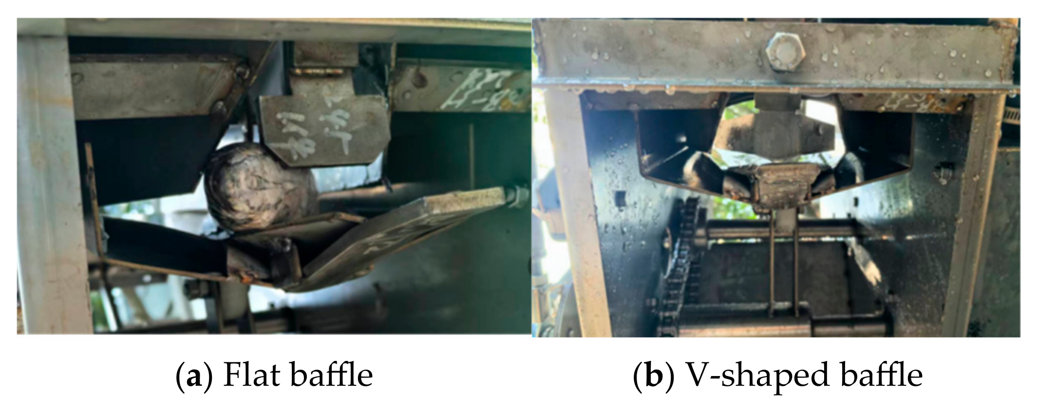
The trigger baffle plate is the key component of the trigger mechanism that withstands the impact force of the fish body, and its shape structure affects the stability of the contact between the fish body and the trigger baffle plate. Based on the characteristics of the impact force generated by the fish sliding down and the shape of the fish head, two structurally simple trigger baffle plates have been designed, as shown in Figure 16.
According to the characteristic of the fish body impacting at an oblique vertical angle, a rectangular flat plate with dimensions of 60 mm×30 mm is designed to withstand the force from the vertical direction. Based on the fish head’s shape, which is approximately an elliptical cone, a V-shaped plate with an opening angle of 70° is designed to achieve multi-point support for the fish head and absorb the collision force of the fish body. Both types of trigger baffle plates have their own characteristics, and subsequent comparative experiments will be conducted to test the triggering effects.

2.9. Design of Electrical Control System

The design of the electrical control system primarily achieves the effects of motor start/stop and speed adjustment. Therefore, the electrical control system of the fish bleeding device mainly consists of a frequency converter, a three-phase AC geared motor, and button switches, as shown in Figure 17. A 380 V three-phase AC power supply is used as the input power source. According to the design requirements, a 400 W vertical three-phase AC geared motor is employed. The frequency converter is used to adjust the frequency to control the output speed of the motor. Waterproof button switches are used to control the on/off of the forward rotation start circuit of the frequency converter, thereby achieving the start/stop control of the motor.

2.10. Fish Bleeding Test

2.10.1. Experimental Materials and Apparatus

Fresh and live snakehead (Channa argus), grass carp (Ctenopharyngodon dellus), and tilapia (Oreochromis mossambicus) were selected as experimental subjects. The body mass of all three fish species ranged from 250 g to 2500 g, with 100 individuals prepared for each species. The fish were harvested from aquaculture ponds and transported under refrigeration to the experimental site. A self-developed automated fish bleeding machine served as the experimental platform (Figure 18). Additional equipment included an electronic balance (accuracy: 0.1 g) and a stopwatch (accuracy: 0.1 s).

2.10.2. Experimental Conditions

The experiment was conducted in November 2024 at the Product Performance Testing Center of Guangdong Hongke Agricultural Machinery Research and Development Co., Ltd. (Guangzhou, China). The ambient temperature during testing was maintained at 25–28 °C. Fish of each species were separately stored in three aquaculture tanks, each equipped with a small aerator to ensure fish vitality during the experiment.

2.10.3. Sensory Evaluation of Bloodletting Efficacy

To assess the bloodletting performance of the automated machine, sensory evaluations were conducted based on fillet color and residual blood content in the muscle tissue to determine the cleanliness of mechanized bloodletting and its impact on fillet quality.
Twenty individuals of each species (snakehead, grass carp, and tilapia) were sequentially fed into the bloodletting machine in a head-first orientation. Fish that completed the bloodletting process were transferred to a clean water pool for free swimming to facilitate further bleeding. Ten minutes later, 10 fish from each species were sampled and filleted into fish fillets. A five-member evaluation panel performed sensory assessments of the bloodletting efficacy for each fillet, following the criteria outlined in Table 3. The sensory scores for each species were used as evaluation indicators, and the comprehensive average score calculated from the panel’s assessments determined the machine’s bloodletting efficacy for each species.

2.10.4. Comparative Test

To test the impact of the trigger baffle plate on the bleeding effect of the automatic fish bleeding machine, a comparative test was conducted using two types of trigger baffle plate designs: the flat plate and the V-shaped plate.
The test method is as follows:
a.
First, install the flat plate on the prototype of the automatic fish bleeding machine, then prepare a batch of live fish and record the total number of fish; press the start button to activate the bleeding machine;
b.
Feed the fish into the machine with their heads facing forward. Once a fish slides out of the exit, feed in the next one until all fish have been processed. For each fish tested, observe whether the bleeding action is successfully triggered and examine the fish after bleeding. If there is a cut on the gill area of the fish head and blood flows out, it is considered a successful bleeding; otherwise, it is a failure. Record the number of successfully bled fish and note the condition of the fish that failed to bleed;
c.
Calculate the trigger success rate and the bleeding success rate for each test.
The formula for calculating the bleeding success rate is
M = N 1 N ×   100 %
The formula for calculating the trigger success rate is as follows.
V = N 2 N ×   100 %
where M—the bleeding success rate;
V—the trigger success rate;
N—the total number of fish, in pieces;
N1—the number of fish that were successfully bled, in pieces;
N2—the number of fish for which the trigger was successful, in pieces;
d.
Repeat the above steps for three tests and calculate the average of the tests;
e.
Remove the flat plate and replace it with the V-shaped plate, then repeat the above steps.

2.10.5. Performance Test

To evaluate the operational performance of the automatic fish bleeding machine, bleeding success rate and work efficiency were used as test indicators for the performance test.
The test method is as follows:
a.
Prepare a batch of live fish and record the total number of fish; press the start button to activate the bleeding machine;
b.
Start the stopwatch and feed the fish into the machine with their heads facing forward. Once a fish slides out of the exit, feed in the next one. Stop the timer after all fish have been processed;
c.
Examine each fish after bleeding. If there is a cut on the gill area of the fish head and blood flows out, it is considered a successful bleeding; otherwise, it is a failure. Record the number of successfully bled fish;
d.
Calculate the bleeding success rate and work efficiency for each test. The bleeding success rate is calculated according to Equation (8).
The formula for calculating work efficiency is
K = 3600 N t
where N—the total number of fish, in pieces;
K—the work efficiency, fish/hour;
t—the total processing time, s;
e.
Repeat the above steps for at least 3 tests and calculate the average of the tests.

3. Results and Discussion

3.1. Results and Analysis of Sensory Evaluation

The sensory evaluation results for bloodletting efficacy are summarized in Table 4. Scores for all three species remained relatively stable and high, indicating minimal or no residual blood in the muscle tissue, with fillet color predominantly bright white. According to the scoring data, sensory ratings were exclusively categorized as 4 or 3 points, with no instances of scores 1 or 2. As shown in Figure 19, fillets rated 4 points exhibited bright white coloration without reddish blood residues, confirming thorough bloodletting. Fillet sections rated 3 points displayed white coloration at the edges but a reddish tint in the central region, with five localized blood residues concentrated in the midsection. This suggests incomplete blood drainage from the central muscle tissue, resulting in reduced product quality. Based on Table 3, the comprehensive average sensory score for the automated bloodletting machine was 3.8, demonstrating its high efficacy for northern snakehead, grass carp, and Nile tilapia. The post-bloodletting fillets exhibited bright white coloration and superior quality.

3.2. Results and Discussion of Comparative Test

Analyzing the experimental data, the comparative test results for the flat baffle and V-shaped baffle are obtained, as shown in Table 5. Through three repeated tests, the average trigger success rate of the bleeding machine with the flat baffle installed is 88.9%, and the average bleeding success rate is 68.9%; with the V-shaped baffle installed, the average trigger success rate of the bleeding machine is 95.6%, and the average bleeding success rate is 93.3%. Therefore, the type of baffle has a significant impact on the bleeding capability of the machine. The trigger success rate and bleeding success rate of the prototype with the flat baffle installed are both lower than those with the V-shaped baffle installed.
The installation conditions of the flat baffle and V-shaped baffle on the bleeding machine are shown in Figure 20. In cooperation with the fish inlet channel, the flat baffle has larger gaps on both sides and a poorer spatial wrapping ability. Figure 20a records the phenomenon of the fish head getting stuck in the gap on one side of the flat baffle during the test, leading to trigger failure. Based on the installation conditions of the baffle on the prototype and the records during the test process, it is analyzed that the V-shaped baffle reduces the gaps on both sides of the baffle and better adapts to the shape of the fish head, which can increase the probability and force of the fish head impacting the baffle. Therefore, the trigger success rate of the bleeding action is higher. The V-shaped baffle can better constrain the position of the fish head, prevent the fish head from tilting, and improve the ability of the bleeding knife to act on the gill area of the fish body, resulting in a higher bleeding success rate. Therefore, according to the test results, the V-shaped baffle is determined to be the optimal structure for the bleeding machine baffle.

3.3. Results and Discussion of Performance Test

In accordance with the requirements of the test method, performance tests were conducted with two indicators: bleeding success rate and work efficiency, as shown in the test process in Figure 21. After the continuous feeding and bleeding discharge of the fish, each fish was checked for the effect of bleeding. The bleeding conditions of snakehead, grass carp, and tilapia are shown in Figure 21b, Figure 21c, and Figure 21d, respectively.
The results of the performance test are shown in Table 6. It can be seen from the table that the results of the five repeated tests are generally stable, with an average bleeding success rate of 94% and an average work efficiency of 1417 fish per hour. According to the survey of fish processing enterprises, the traditional artificial bleeding efficiency is generally 1000 fish/hour. In order to compare the operation efficiency of the bleeding machine with the traditional method, independent sample t-test was carried out.
Zero hypothesis H0: automatic bleeding machine efficiency ≤ manual bleeding efficiency.
t = x μ 2 s / n 6 . 61
where x—average operating efficiency of bleeding machine, fish/hour;
μ 2 —labor bleeding efficiency, fish/hour;
s—standard deviation of working efficiency of bleeding machine;
n—number of tests.
The degree of freedom is 4. According to the table t, the critical value of unilateral inspection t0.05 = 2.132; t > 2.132; reject the null hypothesis.
A 95% confidence interval of working efficiency of the bleeding machine
x ± t 0.025 · s n [ 1258 ,   1576 ]
Therefore, the working efficiency of the bleeding machine was significantly higher than that of the traditional manual bleeding method. Compared with the traditional method, the working efficiency can be improved by 41.7%. The tests showed that the performance indicators of the automatic fish bleeding machine reached the design requirements of a bleeding success rate of ≥90% and a work efficiency of ≥1000 fish per hour, achieving the purpose of mechanized and efficient fish bleeding.
The test used a manual single-grab feeding method, and the process of grabbing the fish took up a certain amount of time, limiting work efficiency. In the future, a flat-laying conveying mechanism should be designed to achieve more efficient feeding. During the test, it was found that due to the differences in fish size, the position of the bleeding knife needs to be adjusted according to the size of the fish. Currently, this is still done manually, and the fish need to be graded before work, adding an extra step to the process. In the future, research should be conducted on bleeding technology and key mechanisms that can adapt to different fish sizes to achieve real-time dynamic adjustments.

4. Conclusions

(1)
Based on the bleeding process at the gill area of fish, an impact-triggered limited bleeding method was proposed, and an automatic fish bleeding machine was designed. Based on the external shape parameters of the fish, by analyzing the motion process and force relationship of the fish sliding down to the trigger baffle plate, a limiting trigger mechanism was designed, achieving position sensing of the fish and automatic triggering of the bleeding action. Based on the quick-return motion characteristic of the offset crank-slider mechanism, by imitating the action process of manual fish killing and bleeding, a reciprocating bleeding mechanism was designed.
(2)
The sensory evaluation trial demonstrated a comprehensive average score of 3.8 for the bloodletting efficacy of the automated fish bloodletting machine. The machine exhibits high efficacy in bleeding for the three tested species—snakehead (Channa argus), grass carp (Ctenopharyngodon idellus), and tilapia (Oreochromis mossambicus). Post-bleeding fillets display bright white coloration with no detectable blood residues, indicating superior product quality. Comparative tests show that the type of baffle has a significant impact on the bleeding capability of the machine, and the V-shaped baffle can be considered as the optimal structure for the bleeding machine baffle.
(3)
The average bleeding success rate of the automatic fish bleeding machine is 94%, and the average work efficiency is 1417 fish per hour. The working efficiency of the bleeding machine is significantly higher than that of the traditional manual bleeding method. Through the continuous action process of directional feeding, posture constraint, limiting trigger, reciprocating bleeding, and automatic sliding out, a cyclic mechanized bleeding effect is achieved.

Author Contributions

Conceptualization, S.X. and Q.L.; methodology, S.X. and L.H.; validation, S.X.; formal analysis, Q.L. and S.X.; investigation, Q.W. and Y.F.; resources, L.H.; data curation, L.G.; writing—original draft preparation, S.X.; writing—review and editing, L.H. and S.X.; visualization, Q.W.; supervision, Q.L.; project administration, L.H.; funding acquisition, Q.L. All authors have read and agreed to the published version of the manuscript.

Funding

This work was mainly supported by the Guangdong Agricultural Scientific Research and Technology Promotion Demonstration Project: Equipment R&D in Processing Weak Links such as Fish Bleeding and Dissection (YCY [2023] No. 6).

Institutional Review Board Statement

Not applicable.

Data Availability Statement

Data are contained within the article. The data presented in this study can be requested from the authors.

Conflicts of Interest

The authors declare no conflicts of interest.

References

  1. Fisheries and Fisheries Administration of the Ministry of Agriculture and Rural Areas. 2024 China Fishery Statistics Yearbook; China Agriculture Press: Beijing, China, 2024. [Google Scholar]
  2. Ouyang, J.; Shen, J.; Zheng, X. Research and application status and development trend of aquatic product processing equipment. Fish. Mod. 2017, 44, 73–78. [Google Scholar]
  3. Dong, S.; Tian, Y.; Xiao, J. Research and application status and Prospect of intelligent fish processing technology. J. Fish. 2024, 48, 16–29. [Google Scholar]
  4. Zhang, W.; Xie, S.; Xu, H. Research on high quality development strategy of China’s aquaculture industry. China’s Eng. Sci. 2023, 25, 137–148. [Google Scholar]
  5. Wei, L.; Li, L.; Ma, R. Research Progress on Key Technologies of fish primary processing equipment. Mod. Agric. Equip. 2023, 44, 2–7. [Google Scholar]
  6. Huang, J.; Cheng, F. Research progress of fish primary processing equipment and automatic monitoring technology. Food Mach. 2019, 35, 204–208+215. [Google Scholar]
  7. Li, L.; Zong, L.; Wang, J. Research status and direction of pretreatment technology and equipment for bulk freshwater fish. Fish. Mod. 2010, 37, 43–46+71. [Google Scholar]
  8. Olsen, S.H.; Joensen, S.; Tobiassen, T.; Heia, K.; Akse, L.; Nilsen, H. Quality consequences of bleeding fish after capture. Fish. Res. 2014, 153, 103–107. [Google Scholar]
  9. Olsen, S.H.; Sorensen, N.K.; Stormo, S.K.; Elvevoll, E.O. Effect of slaughter methods on blood spotting and residual blood in fillets of Atlantic salmon (Salmo salar). Aquaculture 2006, 258, 462–469. [Google Scholar]
  10. Hao, S.; He, J.; Li, L.; Huang, H.; Cen, J.; Ma, H.; Deng, J. Effect of bloodletting on the color of tilapia fillets. Food Ind. Sci. Technol. 2011, 149–151. [Google Scholar]
  11. Shui, B.; Zhao, S.; Han, Z. Systematic Ichthyology; Ocean Press: Beijing, China, 2018. [Google Scholar]
  12. RUMI JAPAN. Fish Processing Machinery Products. Available online: http://www.rumijapan.co.jp/cn/company/index.html (accessed on 10 December 2024).
  13. BAADER. Fish Processing Machinery Products. Available online: https://www.baader.com/fish# (accessed on 15 December 2024).
  14. Wan, P.; Huang, Y.; Wang, R. Design and experiments of the machine vision-based body orientation arrangement convey device for the Scomber japonicus. Trans. Chin. Soc. Agric. Eng. (Trans. CSAE) 2023, 39, 271–282. [Google Scholar]
  15. Wan, P.; Guo, S.; Yang, J.; Zhao, J.; Tan, H.; Zhu, M. Horizontal reciprocating vibration method for head-to-tail directional transportation of fresh water fish. Trans. Chin. Soc. Agric. Eng. (Trans. CSAE) 2021, 37, 40–48. [Google Scholar]
  16. Guo, Z.; Huang, J.; Wang, S.; Yu, S.; Chen, Y.; Zhang, L. Efficient Automatic Method for Head-tail and Ventral-dorsal Directional Transportation of Freshwater Fish. Trans. Chin. Soc. Agric. Mach. 2022, 53, 141–151. [Google Scholar]
  17. Xia, W. Research on Key Technology of Water Jet Descaling Machine for Freshwater Fish. Master’s Thesis, Dalian Polytechnic University, Dalian, China, 2021. [Google Scholar]
  18. Ouyang, J.; Shen, J. Research status and Prospect of fish decontamination technology and equipment. Anhui Agric. Sci. 2023, 51, 19–21. [Google Scholar]
  19. Zhao, M.; Zhai, X.; Lin, M. Optimization and test of the working parameters of the cutting disc for the whole-skin peeling system of snakehead. Trans. Chin. Soc. Agric. Eng. (Trans. CSAE) 2023, 39, 249–255. [Google Scholar]
  20. Li, C.; Shan, H.; Zhang, H. Study on optimization of motion parameters of catfish headless processing device based on FEM. Food Mach. 2022, 38, 89–94. [Google Scholar]
  21. Xie, C. Ichthyology; China Agricultural Press: Beijing, China, 2016. [Google Scholar]
  22. Wang, R.; Yu, H.; Chen, A.; Li, A.; Gao, L.; Zheng, Z. Design and Test of Pneumatic Flipping Comb-type Chrysanthemum Picking Device. Trans. Chin. Soc. Agric. Mach. 2022, 53, 184–193. [Google Scholar]
  23. Wang, Y.; Wang, S.; Dong, Q. Research on isoline of minimum transmission angle of crank slider mechanism and crank rocker mechanism. Mech. Des. Res. 2022, 38, 57–62. [Google Scholar]
  24. Shang, Y. Optimal design of crank slider mechanism based on size drive. J. Lanzhou Jiaotong Univ. 2016, 35, 134–136. [Google Scholar]
  25. Lai, X.; Cheng, J.; Li, S.; Wen, C.; Wei, Y.; Song, J. Design and Experiment of Chassis Levelling Mechanism and Test of Hilly Tracked Sugarcane Harvester. Trans. Chin. Soc. Agric. Mach. 2024, 55, 100–109. [Google Scholar]
Figure 1. Automatic fish bleeding machine. 1. Pre-channel adjustment mechanism. 2. Fish entrance passage. 3. Motor. 4. Frame. 5. Transmission mechanism. 6. Post-channel adjustment mechanism. 7. Trigger mechanism. 8. Bleeding mechanism.
Agriengineering 07 00091 g001
Figure 2. Schematic diagram of impact-triggered dish bleeding method. 1. Bleeding knife. 2. Fish body. 3. Connecting rod. 4. Cam.
Agriengineering 07 00091 g002
Figure 3. Fish outline structure.
Agriengineering 07 00091 g003
Figure 4. Fish entrance passage. 1. Feeding port. 2. Upper channel plate. 3. Channel-supporting plate. 4. Channel side plates. 5. Front channel arc plate.
Agriengineering 07 00091 g004
Figure 5. Schematic diagram of supporting fish head of channel-supporting plate. 1. Support plate. 2. Fish head enveloping model. 3. Side wing plate. 4. Supporting plate. 5. Hinge.
Agriengineering 07 00091 g005
Figure 6. Schematic diagram of spatial coordinates of support plate. Note: a, b, c and d are the four vertices of the conical profile of the support plate.
Agriengineering 07 00091 g006
Figure 7. Bleeding mechanism. 1. Knife holder. 2. Knife holder guide rails. 3. Connecting rod. 4. Drive wheel mechanism.
Agriengineering 07 00091 g007
Figure 8. Kinematic diagram of the bleeding mechanism. Note: θ is the extreme position angle, °; rmin is the minimum transmission angle, °; a is the length of the crank AB, mm; b is the length of the connecting rod BC, mm; e is the eccentric distance, mm. 1. Drive wheel. 2. Knife holder.
Agriengineering 07 00091 g008
Figure 9. Bleedingg knife. 1. Bleeding knife A. 2. Bleeding knife B.
Agriengineering 07 00091 g009
Figure 10. Transmission mechanism. 1. Transmission rod. 2. Channel-supporting plate drive wheel. 3. Trigger rotating arm. 4. Clutch assembly. 5. Bleeding drive wheel. 6. Transmission chain. 7. Tension wheel. 8. Driving wheel.
Agriengineering 07 00091 g010
Figure 11. Clutch assembly. 1. Return spring. 2. Rotating sleeve. 3. Cam roller frame. 4. Roller. 5. Passive star wheel. 6. Active hub.
Agriengineering 07 00091 g011
Figure 12. Schematic diagram of the opening and closing state of the clutch assembly. Note: F3 is the friction force exerted by the active hub on the roller, N; F4 is the friction force exerted by the roller on the passive star wheel, N; F5 is the pressure exerted by the roller on the passive star wheel, N. 1. Roller. 2. Passive star wheel. 3. Active hub.
Agriengineering 07 00091 g012
Figure 13. Trigger mechanism. 1. Trigger baffle plate. 2. Trigger arm. 3. Pillow block bearing. 4. Trigger shaft. 5. Spring. 6. Trigger rod.
Agriengineering 07 00091 g013
Figure 14. Manual trigger mechanism. 1. Trigger link. 2. Trigger handle.
Agriengineering 07 00091 g014
Figure 15. Kinematic diagram of the trigger mechanism. Note: o is the center of the trigger rotation shaft; b is the contact point between the fish head and the trigger baffle plate; ab is the inclined plane of the channel-supporting plate; c is the position where the spring tension acts; d is the contact point between the trigger rod and the clutch drive cam; e is the contour vertex of the cam; F1 is the initial tension of the spring, N; and m is the mass of the fish body, kg. 1. Fish. 2. Cam.
Agriengineering 07 00091 g015
Figure 16. Trigger baffle plate.
Agriengineering 07 00091 g016
Figure 17. Schematic diagram of the electronic control system. Note: UF represents the frequency converter, M represents the three-phase AC geared motor, and SB represents the button switch.
Agriengineering 07 00091 g017
Figure 18. Automatic fish bleeding machine.
Agriengineering 07 00091 g018
Figure 19. Fish fillet after bleeding. The circled parts in the figure show the blood residue in the muscle tissue of fish.
Agriengineering 07 00091 g019
Figure 20. Installation of two baffles.
Agriengineering 07 00091 g020
Figure 21. Performance test.
Agriengineering 07 00091 g021aAgriengineering 07 00091 g021b
Table 1. Main technical parameters of fish bleeding machine.
ParameterValue/Type
Overall dimension (L × W × H)1070 mm × 540 mm × 1140 mm
Driving modeMotor drive
Power0.4 kW
Motor output speed90 r/min
Bleeding success rate of≥90%
Working efficiency≥1000 fish per hour
Table 2. Main body shape parameters of fish.
TypeQuality/gFish Length
/mm
Fish Head Length/mmFish Head Height/mmFish Head Width/mmMaximum Sliding Friction Angle/(°)
Snakehead692.7 ± 188.2407.1 ± 29.4100.6 ± 8.157.6 ± 4.856.4 ± 6.710
Grass carp1174.6 ± 204.5473.3 ± 31.5116.1 ± 7.292.6 ± 6.558.4 ± 5.214
Silver carp890 ± 102435.2 ± 15.8112.6 ± 5.2107.2 ± 7.152.7 ± 3.225
Tilapia512 ± 42281 ± 1028.271 ± 2.299 ± 4.244.8 ± 0.419
Table 3. Sensory evaluation criteria.
Score4321
Scoring criteriaBright white fillet coloration with no blood residues detected in the muscle tissueSlightly reddish fillet coloration with minimal blood residues present in the muscle tissueModerately reddish fillet coloration accompanied by localized blood residues within the muscle tissueDark reddish fillet coloration with numerous blood residues distributed throughout the muscle tissue
Table 4. Sensory evaluation test results.
FishGrass CarpTilapiaSnakehead
Average score3.83.93.7
Table 5. Record of comparative test results.
Baffle TypeTest Serial NumberTotal Fish Quantity
/Piece
Triggered Successfully Number
/Piece
Number of Successful Bleeding
/Piece
Trigger Success RateSuccess Rate of Bleeding
Flat baffle115141193.3%73.3%
215131086.7%66.7%
315131086.7%66.7%
V-shaped
baffle
115141493.3%93.3%
2151514100%93.3%
315141493.3%93.3%
Table 6. Performance test result record.
Number of tests12345
Total fish quantity/piece2030303030
Successful quantity/piece1828283028
Time/s5476907068
Bleeding success rate90%93.3%93.3%100%93.3%
Operation efficiency (fish/h)13331421120015421588
Disclaimer/Publisher’s Note: The statements, opinions and data contained in all publications are solely those of the individual author(s) and contributor(s) and not of MDPI and/or the editor(s). MDPI and/or the editor(s) disclaim responsibility for any injury to people or property resulting from any ideas, methods, instructions or products referred to in the content.

