Article

Control of Magnetic-Navigation Pigeon Farm-Cleaning Robot Based on Fuzzy PID and Kalman Filter

1
College of Mechanical and Electrical Engineering, Zhongkai University of Agriculture and Engineering, Guangzhou 510225, China
2
Guangdong Institute of Modern Agricultural Equipment, Guangzhou 510630, China
3
Foshan Zhikong Future Technology Co., Ltd., Foshan 528000, China
4
College of Automation, Zhongkai University of Agriculture and Engineering, Guangzhou 510225, China
*
Author to whom correspondence should be addressed.
AgriEngineering 2025, 7(10), 351; https://doi.org/10.3390/agriengineering7100351
Submission received: 11 September 2025 / Revised: 1 October 2025 / Accepted: 13 October 2025 / Published: 17 October 2025

Abstract

In pigeon farming, manure cleaning is predominantly manual, a method that is both slow and costly, and exposes workers to harsh conditions. Addressing these challenges, this paper introduces a cleaning robot for pigeon farms utilizing magnetic strip navigation combined with RFID signal recognition and derives the magnetic-navigation control model. This method can improve operational stability and accuracy. Given the farm’s unstable environment, a control algorithm based on fuzzy PID with Kalman filtering was developed. This algorithm mitigates input disturbances and measurement noise by integrating Kalman filtering into the fuzzy PID feedback loop, thereby refining signal accuracy. Numerical simulations conducted in Matlab/Simulink demonstrate that the inclusion of Kalman filtering reduces the time of target signal tracking by nearly 1 s compared to fuzzy PID and by almost 2 s relative to standard PID under identical disturbances. Experimental tests confirm that this algorithm significantly improves the robot’s operational stability and reduces magnetic-navigation deviation, underscoring its advancement and practicality over traditional PID and fuzzy PID methods.

1. Introduction

In the pigeon-breeding industry, using robots to replace manual labor to complete the work of feeding and cleaning manure is a topic worthy of study. The establishment of cleaning robots can solve the problem of manual manure cleaning and has good prospects for application [1,2]. Cleaning robots utilize a range of navigation methods, including LIDAR, vision, satellite, inertial, and magnetic navigation. Typically, the first four methods exhibit high efficiency, robust navigation accuracy, intelligence, and flexibility [3,4,5,6]. The pigeon-farming environment is typically suboptimal, characterized by dirty ground and pigeons being raised in cages within large factories in China, where light intensity fluctuates. Moreover, signal reception is often unstable. Therefore, this study opts for magnetic navigation due to its robust anti-interference properties and high stability. Magnetic navigation is commonly implemented using conventional PID control or fuzzy PID control methods [7].
The PID control algorithm, a common classical control method, is widely used in control systems to achieve rapid and precise processing of system inputs, leading to the attainment of desired outputs [8,9,10,11]. The traditional PID control algorithm relies on a trial-and-error approach to adjust its parameters, making it challenging to achieve optimal control. This often results in suboptimal tuning and significant overshoot, particularly in nonlinear and time-varying systems [12,13,14]. The fuzzy PID control algorithm enables real-time parameter tuning and achieves adaptive PID control for control systems. Moreover, it delivers excellent control performance even in nonlinear systems. This algorithm integrates fundamental theories such as fuzzy set theory, fuzzy linguistic variables, and fuzzy logic reasoning [15]. Yu et al. [16] employed a fuzzy PID algorithm in the medicinal herb-transplanting machine’s electronic control system to ensure the transplanting speed precisely matched the machine’s. Zhu et al. [17] showed that the implementation of a fuzzy PID control algorithm in the four-wheel steering system of a hillside tractor significantly decreased the average stabilization time of the yaw rate. Zhao et al. [18] proposed a general fuzzy gain-scheduling PID controller to achieve self-balancing adjustment of power-line inspection robot systems. Kodagoda et al. [19] studied the development and practical applications of an intelligent stable fuzzy proportional-differential proportional-integral (PD-PI) controller in AGV steering and speed control. Men et al. [20], utilizing fuzzy control technology, examined proportional feed-forward and fuzzy feedback-control strategies for four-wheel steering vehicles. Simulations indicated that fuzzy control positively influenced rear-wheel steering responses.
While working in pigeon farms, robots are inevitably influenced by output noise and input disturbances. Additionally, the dusty environment of the pigeon farm can compromise sensor accuracy. Given that the sensor’s measurement noise predominantly follows a Gaussian white noise distribution, the Kalman filter, known for its efficacy in mitigating Gaussian white noise, is implemented to diminish both the measurement noise and process noise within the magnetic-navigation control system [21]. Wang et al. [22] constructs a Kalman filter-based attitude estimation scheme by integrating the AutoRegressive (AR) model, designs a double-gain Proportional-Derivative (PD) controller, and verifies through experiments that the scheme enables stable attitude control and hovering of the quadrotor on the test bench. Querino et al. [23] recommend using Kalman filtering for aircraft attitude control, with quaternions as the state variables and accelerometers as the state update measurements. Wu et al. [24] used the Kalman filter algorithm to achieve real-time tracking of mobile robots.
In summary, it can be concluded that fuzzy PID and Kalman filter technologies are advanced and widely used. This study focused on developing a cleaning robot for pigeon farms utilizing magnetic navigation for robot guidance, derived the magnetic-navigation control model, and integrated a fuzzy PID control system with Kalman filtering. Finally, the design was validated using numerical simulation and experimental testing. The experimental results proved the practicality and advanced nature of the algorithm. Through experiments, the key performance of the robot is verified and analyzed, providing a reference for the research, development, and application of intelligent cleaning equipment in livestock farms.

2. Working Principle and Control System Design

2.1. Introduction to the Work Environment

The pigeon-farm environment is shown in Figure 1. Its structure consists of multiple layers of pigeon cages stacked together to form a row, with a passageway in the middle. Each row of pigeon cages in the pigeon farm has an exit at both ends. The figure illustrates variations in passageway cleanliness, lighting intensity, and the quantity and composition of manure beneath pigeon cages. These discrepancies necessitated the robot’s capacity to adeptly adapt to diverse conditions, underscoring the significance of upholding operational stability. Pigeon farms generally have four rows of pigeon cages, with two columns joined together to form a row. The working passage between the cages is approximately 1.5 m wide. Pigeons are housed in three-tiered cages constructed from galvanized steel wire mesh. Each row of cages measures 50 m in length, 0.8 m in width, and 2 m in height, with the cages positioned 0.3 m above the ground. The primary task of manual manure cleaning is to push the accumulated waste from under the pigeon cages to the passageway for centralized disposal.

2.2. Overall Structure of the Robot

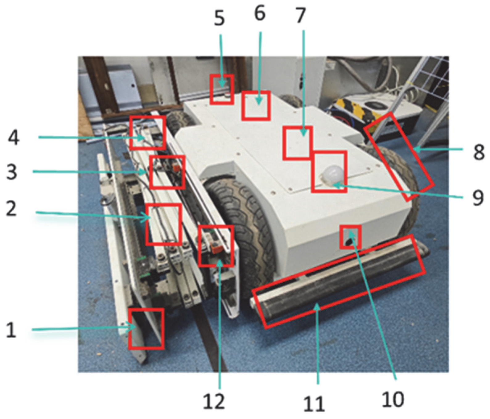
The pigeon farm-cleaning robot comprises a walking mechanism, cleaning mechanism, and control system. The walking mechanism, depicted in Figure 2, utilizes a four-wheel differential system to facilitate movement and enhance adaptability to the confined spaces within the pigeon farm. The walking mechanism of the robot includes various components, including encoders for speed measurement and distance calculation, RFID card readers for executing corresponding actions based on stored information, ultrasonic sensors for obstacle detection and avoidance, touch sensors at the front and rear to halt the robot upon encountering obstacles, indicator lights (green for autonomous navigation, red for RFID card detection), emergency stop buttons for immediate halting in emergencies, motor modules for movement, and remote-control modules for operator control and positioning, with an effective distance of 10 m. The encoder measures speed and distance, the RFID reader processes stored information, the ultrasonic sensor is used for obstacle detection, with an effective detection-distance range of 10 cm to 50 cm, and touch sensors trigger halting upon obstacle detection. Indicator lights signify navigation status, and the emergency stop button ensures immediate halting during malfunctions or emergencies. The remote-control module allows operators to control and position the robot, with a mode change button for quick intervention in case of malfunctions, ensuring operational security. The magnetic-navigation sensor guides the robot along planned paths.
The scissor-type telescopic mechanism can be seen in Figure 2, situated on the robot’s right side, which is powered by a gear-driven DC motor. The extension length is adjustable through the incorporation of Hall sensors, and its maximum extension can reach up to 2 m. Additionally, two universal wheels are installed at the bottom of the plate brush, which not only provide structural support but also enable lateral cleaning work and longitudinal movement. At the extremity, a retractable plate brush is mounted. This brush descends during cleaning operations to enhance ground friction, thereby boosting cleaning effectiveness. Conversely, when retracted, the plate brush ascends to minimize friction and optimize efficiency.
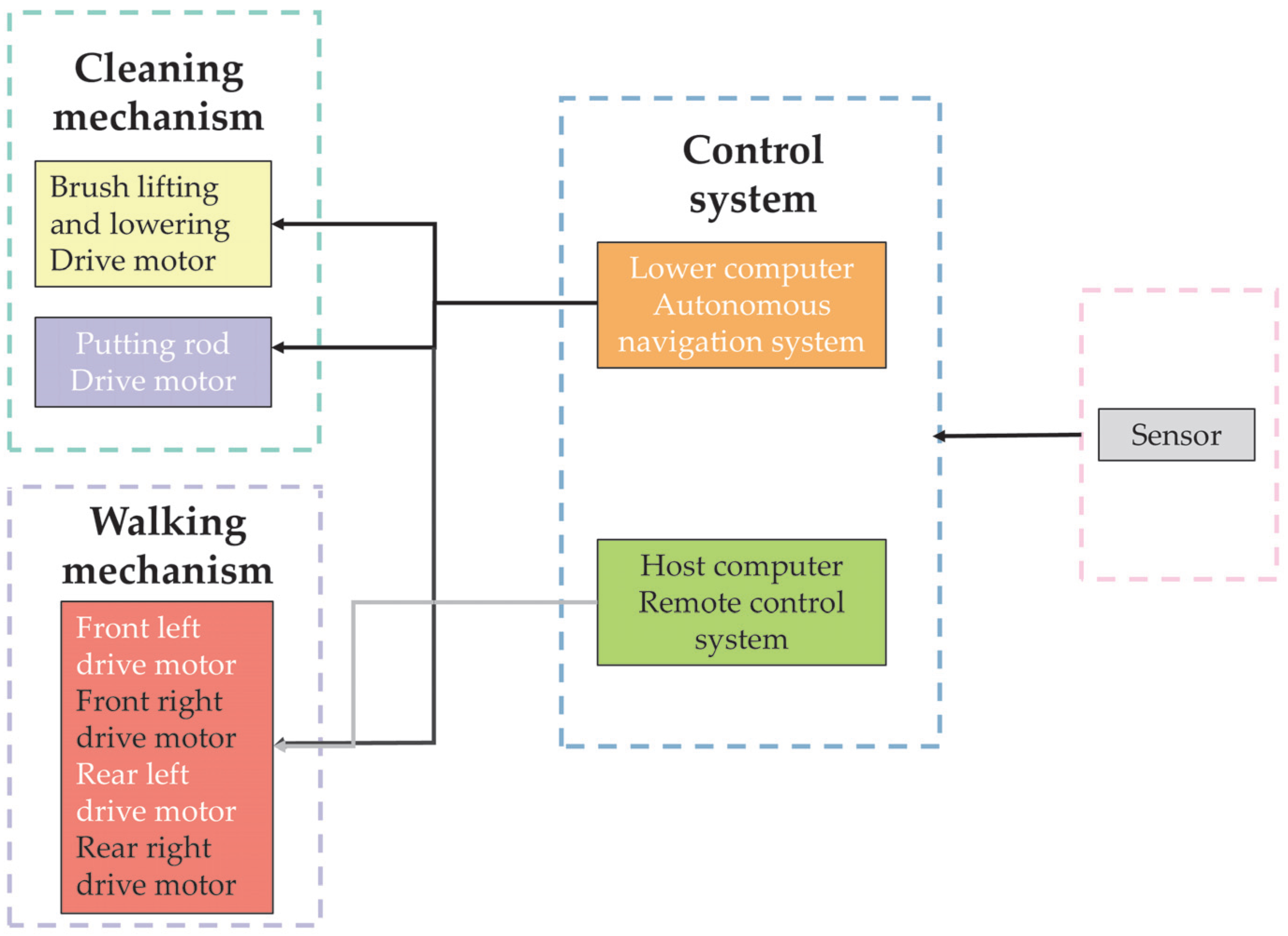
The walking and cleaning mechanisms are each equipped with independent control chips (Stm32f103c8t6) that communicate via a Controller Area Network (CAN) bus. The control system operates in two modes: remote-control and autonomous navigation. In remote-control mode, the robot’s movement and positioning are managed. In autonomous navigation mode, the robot tracks predefined magnetic strips, relaying sensor data to the walking mechanism. The primary controller processes this data to adjust the speed of the four-wheel drive motor using Pulse Width Modulation (PWM). Upon detecting an RFID card, information from the card is transmitted via the CAN bus to the control chip of the cleaning mechanism to determine whether to activate the motor module. The control structure diagram is depicted in Figure 3.

2.3. Working Principle

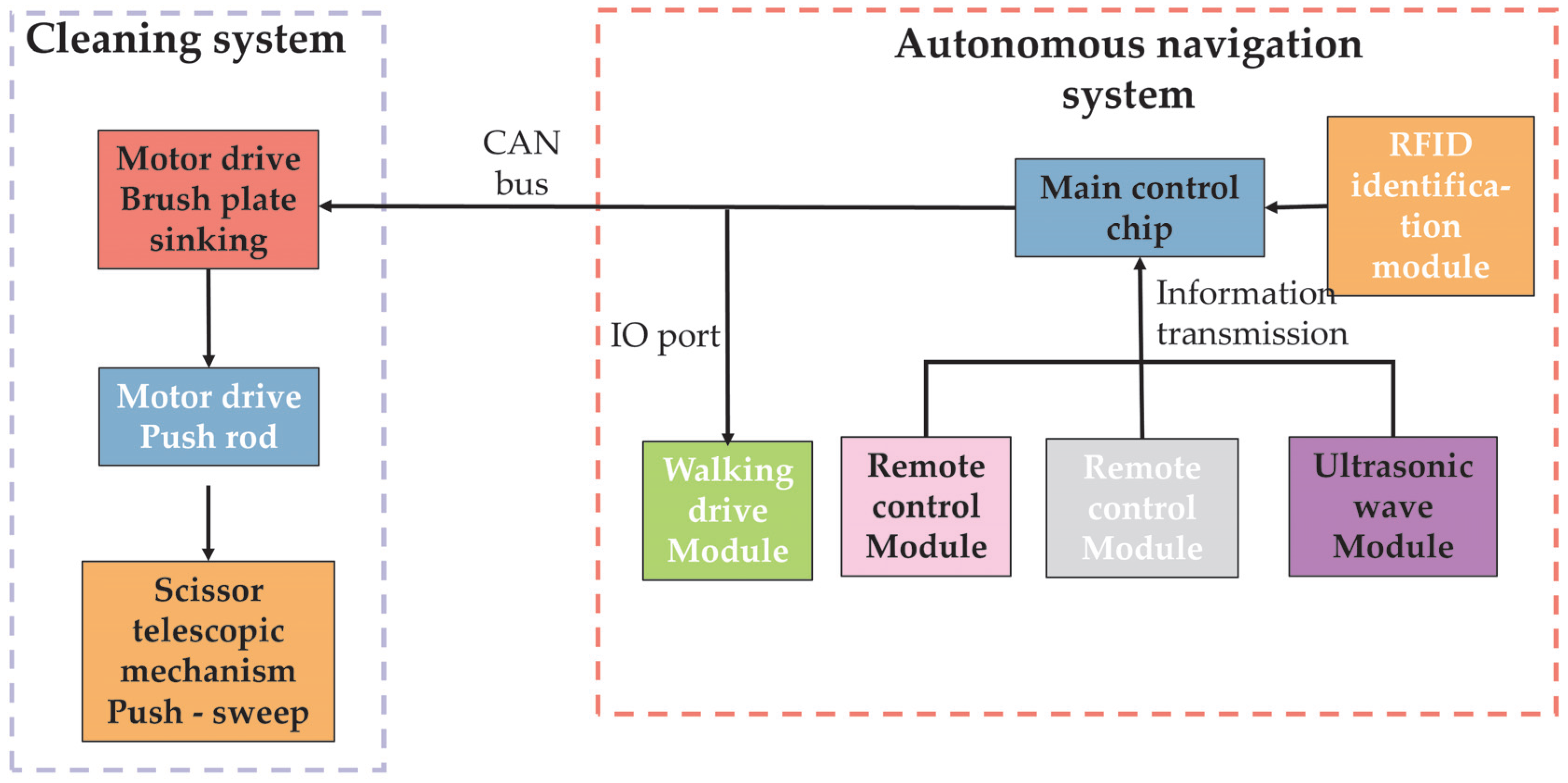
The working principle diagram is shown in Figure 4. The workflow encompasses both autonomous navigation control and cleaning functionalities. Cleaning tasks are executed through the synchronization of the walking and sweeping mechanisms. The operational sequence is as follows: the magnetic-navigation sensor detects magnetic induction signals, enabling the robot to autonomously track the magnetic strip. By leveraging the magnetic-navigation deviation, the robot regulates the speed of the left and right walking motors to refine its walking posture. RFID cards are strategically positioned along the magnetic strip. Upon card recognition, the robot activates the scissor-type telescopic mechanism to commence the cleaning operation.

2.4. Software Design

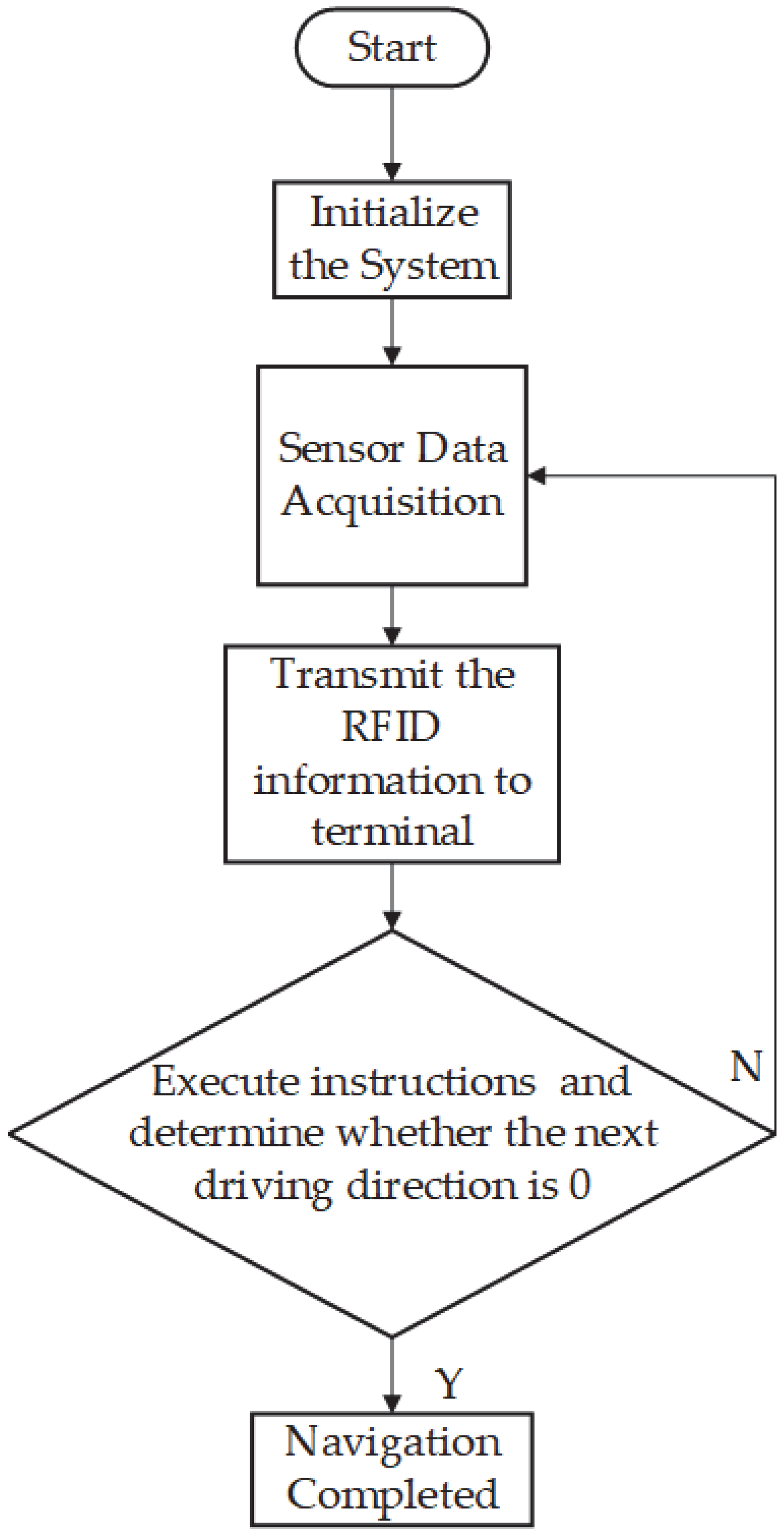
Figure 5 illustrates the workflow of the primary program. Initially, the system is initialized, followed by sensor data collection, RFID card identification using the card reader on the magnetic strip, and subsequent commencement of cleaning operations. During autonomous operation, the robot continuously monitors the presence of an RFID card on the magnetic strip, reads its unique data in real time, and transmits this information to the terminal. Successful identification and transmission prompt a pause in running for cleaning; otherwise, the robot proceeds forward. Concurrently, it plans the subsequent driving direction based on the Breadth-First Search (BFS) algorithm while executing cleaning tasks. Upon completion of the cleaning assignment, the robot resumes its activities until the entire navigation task is accomplished.

2.5. Cleaning Path Setting

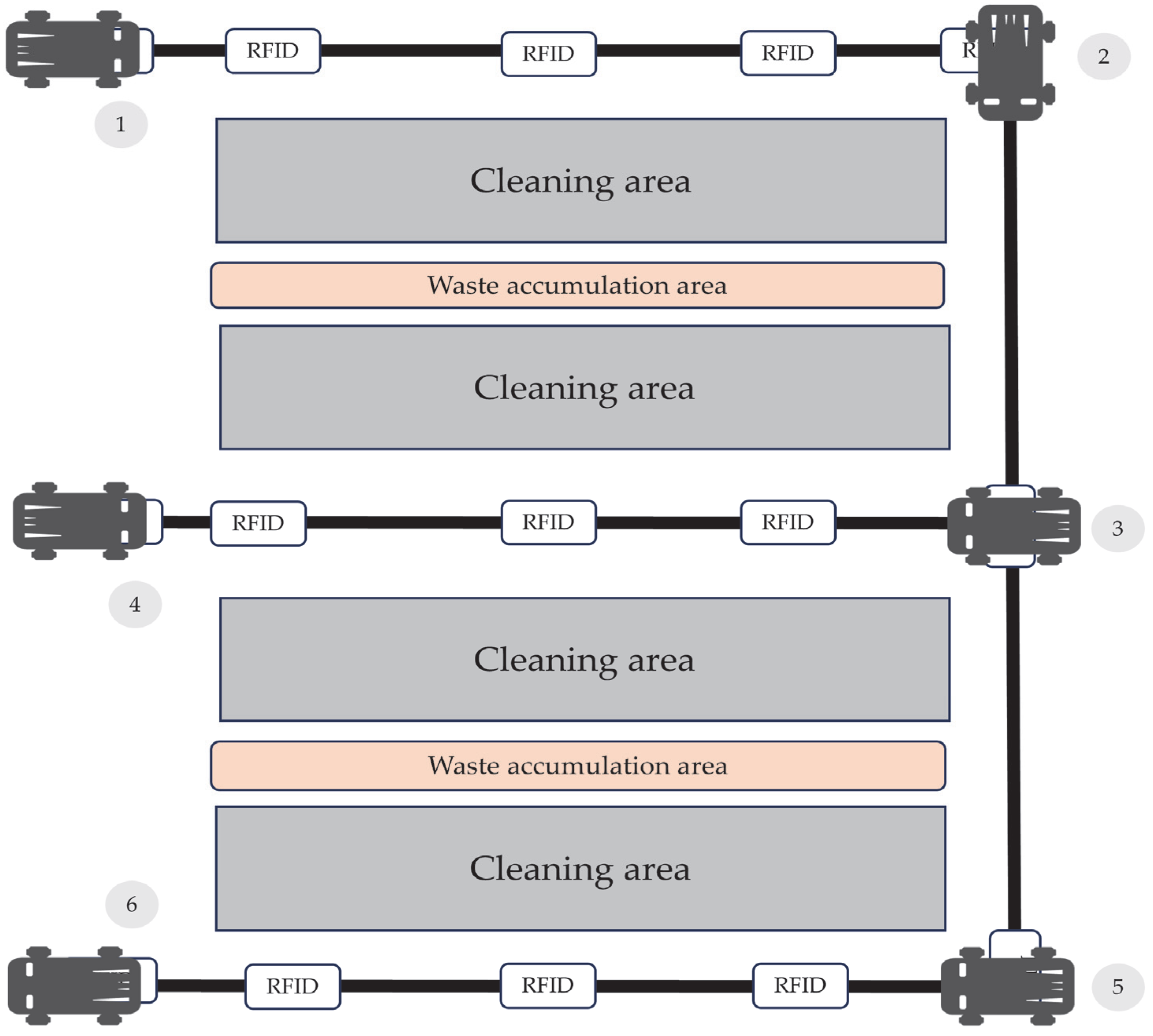
As shown in Figure 6, the pigeon farm layout is divided into a cleaning area, waste storage area, and magnetic strip track. The initial RFID card placed on the magnetic strip serves as the primary positioning point or starting point. Following manual positioning via remote control, the robot commences autonomous navigation along the magnetic-strip track. Upon detecting an RFID card embedded with cleaning instructions on the magnetic strip, the robot initiates the cleaning process, systematically addressing each designated cleaning area. Upon reaching point 2, the robot identifies an RFID card specifying a turning direction, determining the subsequent path. At point 3, an RFID card indicating a right turn is recognized. Upon completion of the cleaning task, the robot proceeds to point 4, where it encounters an RFID card signaling a U-turn, leading to the cleaning of the opposite side of the designated area. Returning to point 3, another right turn is indicated by the RFID card. Subsequently, the robot advances to point 5, where a right turn is again identified, concluding the cleaning task. Finally, upon reaching point 6 and detecting an RFID card with a stop command, the robot completes the entire cleaning operation.

3. Design of the Robotic Magnetic-Navigation Control Model

The pigeon farm-cleaning robot in this study is powered by a DC motor differential drive system. During navigation, the driving speed and position deviation can be adjusted by regulating the speed of the left and right drive wheels. The drive system comprises a main control chip, a motor drive module, DC motor (5Nm 24v), driving wheels, and a real-time speed-measuring encoder. The schematic representation of this system is depicted in Figure 7.
In this design, the armature voltage switching time is adjusted with a PWM algorithm to control the motor speed. Motor drive PWM is modulated using PID control algorithm. The transfer function of the PID control loop is as follows:
G 1 ( s ) = K p + K i 1 s + K d s
Kp, Ki, and Kd are the proportional, integral, and derivative coefficients, respectively.
The voltage of the left and right drive wheels can be expressed by the following formula:
U = V 1 + T m
V is the linear velocity of the drive wheel, and Tm is the motor response time.
The lag loop of the DC-motor PWM speed control can be equivalent to a first-order regulating inertia loop, and its transfer function is as follows:
G 2 ( s ) = U d U c = K s T s s + 1
Ud is the average no-load voltage; Uc is the pulse-width-modulation control voltage; Ks is the amplification coefficient; and Ts is the average lag time.
The armature circuit of a DC motor satisfies Kirchhoff’s voltage law:
U ( t ) = R e q i ( t ) + L d i ( t ) d t + E
U(t) is the armature input voltage, Req is the armature resistance, L is the armature inductance, i(t) is the armature current, and E is the counter-electromotive force.
The counter-electromotive force is proportional to the rotational speed, expressed in the following formula:
E = K ω ( t )
K is the counter-electromotive force constant, and ω t is the angular velocity of the motor.
The motor torque balance equation is as follows:
J d ω ( t ) d t = T e m B ω ( t ) T load   ( t )
J: Moment of inertia.
B: Viscous damping coefficient.
Tem: Electromagnetic torque.
Tload(t): Load torque.
The electromagnetic torque formula is as follows:
T e m ( t ) = C i ( t )
C is the torque constant.
Ignoring the inductance, the armature circuit equation can be simplified as follows:
U ( t ) = R e q i ( t ) + K ω ( t )
The next equation is as follows:
i ( t ) = U ( t ) K ω ( t ) R e q
Substituting this into the electromagnetic torque Equation (7), we then arrive at the following equation:
T e m ( t ) = C E ( t ) K ω ( t ) R e q
Ignoring the load and substituting Equation (10) into the torque balance Equation (6), we then arrive at the following equation:
J d ω ( t ) d t = C R e q ( E ( t ) K ω ( t ) ) B ω ( t )
This can be simplified as follows:
J d ω ( t ) d t = C R e q E ( t ) K C R e q B ω ( t )
Taking the Laplace transform of the above equation, we arrive at the following equations:
J s Ω ( s ) = C R e q E ( s ) K C R e q + B Ω ( s )
Ω ( s ) = C R e q J s + B + K C R e q E ( s )
We can obtain the transfer function of the DC-motor model using the following equation:
G 3 ( s ) = Ω ( s ) E ( s ) = C R e q J s + B + C K R
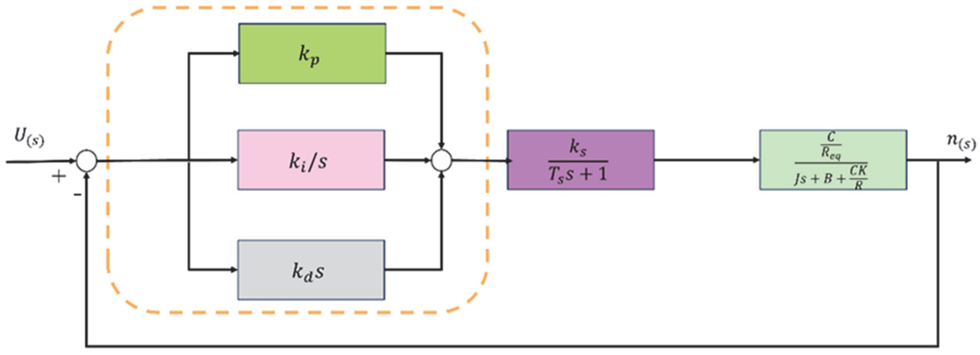
The PID speed control system is shown in Figure 8:
According to Mason’s formula, the transfer function is as follows:
G 3 ( s ) = n ( s ) U n ( s ) = G 0 ( s ) 1 + G 0 ( s )
The expression of G0(s) is as follows:
G 0 ( s ) = G 1 ( s ) G 2 ( s ) G 3 ( s )
Substituting G1(s), G2(s), and G3(s) into Equation (17) gives the transfer function expression as follows:
G ( s ) = K p + K i 1 s + K d S K s T s + 1 C R e q J s + B + C K R 1 + K p + K i 1 s + K d S K s T s + 1 C R e q J s + B + C K R
By substituting each parameter, the transfer function is obtained as follows:
G ( s ) = 3.8 s 2 + 3.75 s + 1.25 s 4 + 1.5 s 3 + 0.5 s 2

4. Design of Magnetic-Strip Autonomous Navigation Control Algorithm

4.1. Fuzzy PID Control-System Model

The position-type control equation of the discrete PID controller is
v ( n ) = v o + K p e ( n ) + K i = 1 n e ( i ) + K d ( e ( n ) e ( n 1 ) )
v(n): The speed of the driving wheel at the nth sampling time point, m/s.
V0: The initial speed of the driving wheel, m/s.
Kp: Proportional coefficient.
e(n), e(n−1): The magnetic-navigation deviation at the nth and (n − 1)th sampling time points.
Ki: Integral coefficient.
Kd: Differential coefficient.
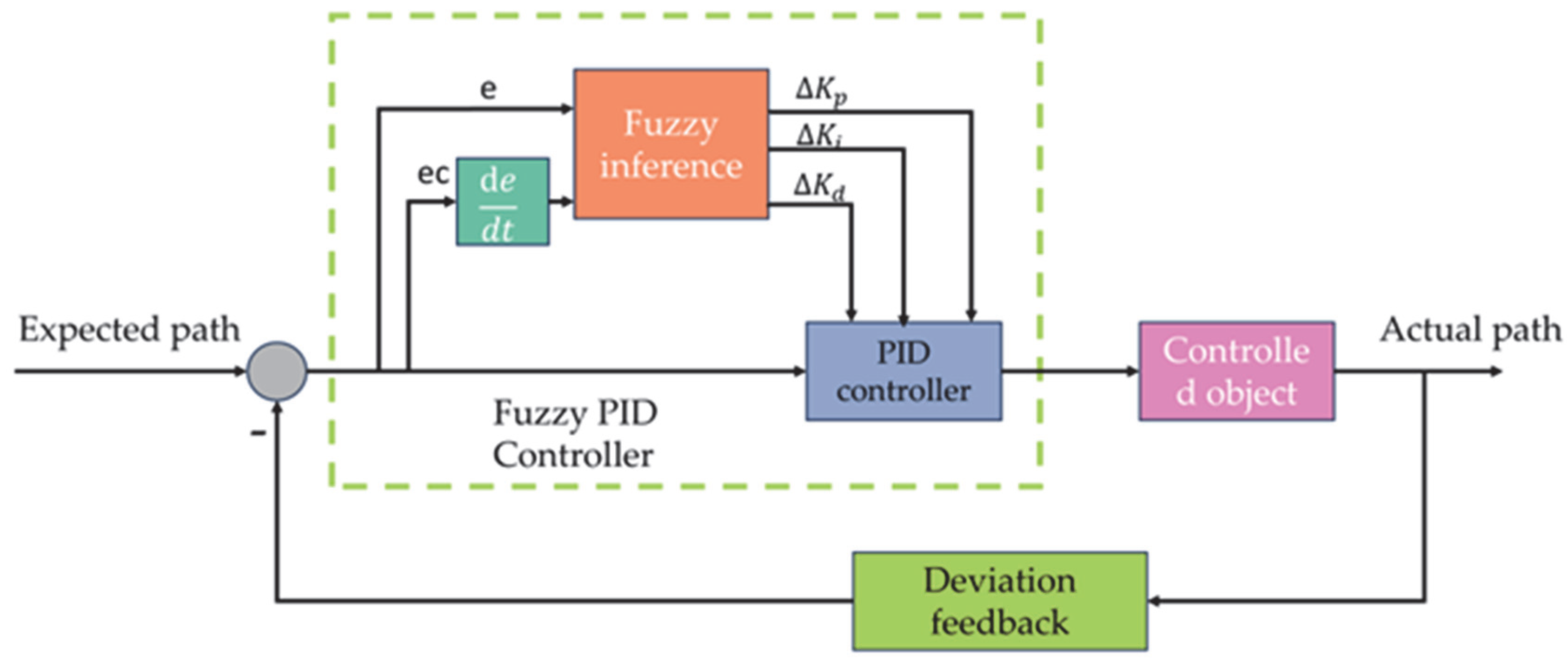
The PID controller utilizes the magnetic-navigation deviation e(n) as its input and the drive motor speed of the robot as its output. The three fixed coefficients of the conventional PID control may lead to substantial oscillations or slow responses when the magnetic-navigation deviation exceeds a certain threshold, potentially compromising navigation accuracy. Consequently, real-time adjustment of the PID control coefficients is essential, necessitating the incorporation of fuzzy control technology. The control-system model, depicted in Figure 9, features the magnetic-navigation deviation e and its rate of change ec as inputs, with the adjusted actual magnetic-navigation path controlled by regulating the motor speed serving as the output.
The fuzzy PID control rules for the left and right wheels of the pigeon farm-cleaning robot are shown in Equations (21) and (22).
v L ( n ) = v 0 L K p + Δ K p e ( n ) K i + Δ K i i = 1 n e ( i ) K d + Δ K d ( e ( n ) e ( n 1 ) )
vL(n): The speed of the left driving wheel at the nth sampling time point, in m/s.
v0L: The initial speed of the left drive wheel, m/s.
v R ( n ) = v 0 R + K p + Δ K p e ( n ) + K i + Δ K i i = 1 n e ( i ) + K d + Δ K d ( e ( n ) e ( n 1 ) )
vR(n): The speed of the right driving wheel at the nth sampling time point, in m/s.
v0R: The initial speed of the right drive wheel, m/s.

4.2. Fuzzy Controller Rule Design

The core of fuzzy controllers is to formulate reasonable and effective fuzzy rules. Based on past experience and extensive experimentation, it is known that there is an optimal adjustment relationship between magnetic-navigation deviation, deviation change rate, and ∆Kp, ∆Ki, and ∆Kd. Combining the characteristics of magnetic-navigation sensors and experimental results, we can obtain the domains and fuzzy subsets of fuzzy controllers. The magnetic-navigation sensor is installed on the middle axis of the robot and has 18 detection points, each spaced 1 cm apart, detecting that the height is 10 cm. The magnetic strip is 3 cm wide. When the robot navigates autonomously without deviation, this means that the four detection points in the center of the sensor detect the magnetic strip, so the magnetic deviation of the robot is ±6 cm. The basic domain for magnetic deviation is [−6, 6], with −6 to −4 being negative large, −4 to −2 being negative medium, and −2 to 0 being negative small. The deviation change rate domain can be set to [−3, 3]. The fuzzy domains of the parameter adjustment quantities ΔKp, ΔKi, and ΔKd can each be divided into the following seven quantization levels: ΔKp, ΔKi, ΔKd = {NB, NM, NS, ZO, PS, PM, PB}. The domain of the proportional coefficient Kp is [−7, 7]; the domain of the integral coefficient Ki is [−7, 7]; and the domain of the differential coefficient adjustment quantity Kd is [−2, 4]. The fuzzy control logic is as follows: When there is a severe deviation from the predetermined path, increase the speed difference between the drive wheels to make a quick correction. For moderate deviations from the predetermined path, adjust the speed of the drive wheels according to the rate of deviation change. For slight deviations from the predetermined path, make slight adjustments to the speed of the drive wheels. The fuzzy rules for ΔKp, ΔKi, and ΔKd are shown in the Table 1 below.
By observing the characteristics of the surface plot (Figure 10) revealing that both the proportional coefficient adjustment and differential adjustment rules exhibited effective gradient distribution. The fuzzy mapping between input and output closely adhered to the theoretical design. Regarding the differential coefficient adjustment rules, it is recommended to increase the coefficient appropriately when encountering significant magnetic-navigation deviation. By utilizing the differential link, one can forecast deviation patterns in advance, facilitating predictive and feedback-control strategies.

4.3. Kalman Filter Model Establishment

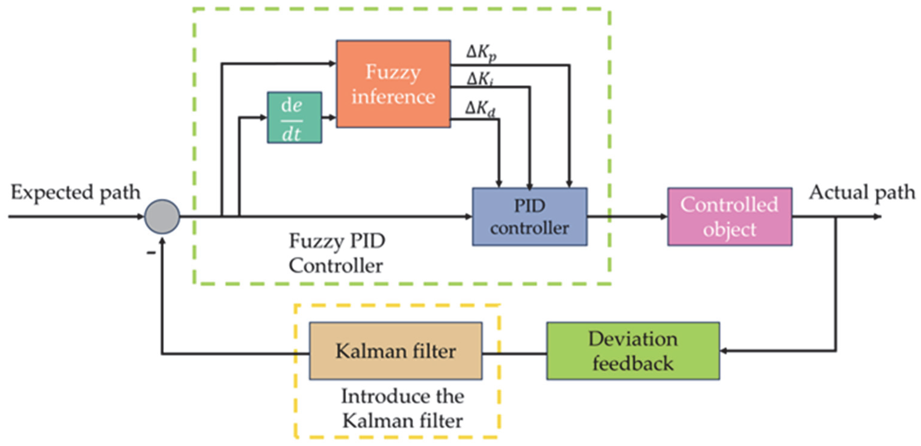
A suitable Kalman filter model is chosen to optimize the state estimation of the deviation process of pigeon farm-cleaning robots by analyzing their motion characteristics. Figure 11 illustrates the magnetic-navigation control system, which uses the anticipated magnetic-navigation path as input to generate the actual navigation path for the robot. This output is then looped back to the input through a Kalman filter, establishing a comprehensive feedback system.
To maintain the stability of the pigeon farm-cleaning robot during magnetic navigation, only lateral movements are relevant. Therefore, we focus on lateral deviation (e) and its rate of change as state variables. At time tk, let the lateral offset of the robot be ek, the offset change rate be k, the system disturbance be d, and the sampling period be t. Denoting X as the state variable, we can express this as follows:
X = e e d
e: Lateral deviation of the magnetic strip center line.
e ˙ : Deviation change rate.
d: System disturbances, such as changes in ground friction, load disturbances, etc.
Assume that the disturbance acceleration is constant and establish a discrete state transition model:
X k = f X k 1 , u k 1 + w k = e k 1 + e ˙ k 1 Δ t + 0.5 d k 1 Δ t 2 e k 1 + d k 1 t d k 1 + w k
Uk−1: Control input.
wk~N(0,Q): Process noise, Q is the process noise covariance matrix, Q = [0.1, 0.5, 0.2].
Select the actual deviation measurement value as the observed quantity. Let the measurement value at time tk be Zk, and the observation model is as follows:
Z h = h X k + v k = 1 0 0 X k + v k
vk~N(0,R): Observation noise, R is the measurement noise covariance matrix, R = 0.5.
Perform linearization of the Kalman filter, calculate the Jacobian matrices F (state transition) and H (observation).
A = F = f X X k 1 = 1 Δ t 0.5 Δ t 2 0 1 Δ t 0 0 1
H = h X = [ 1.0.0 ]
The Kalman filter prediction equation is as follows:
The state prediction equation is as follows:
X ^ k = f X k 1 , u k 1
The covariance prediction equation is as follows:
P k = A P k 1 A T + Q
The Kalman filter update equation is as follows:
The Kalman gain calculation is as follows:
K k = P k H T H P k H T + R
The status update is as follows:
X ^ k = X ^ k + K k Z k H X ^ k
The covariance update is as follows:
P k = I K k H P k

5. Simulation Analysis and Experimental Testing

5.1. Simulation Analysis

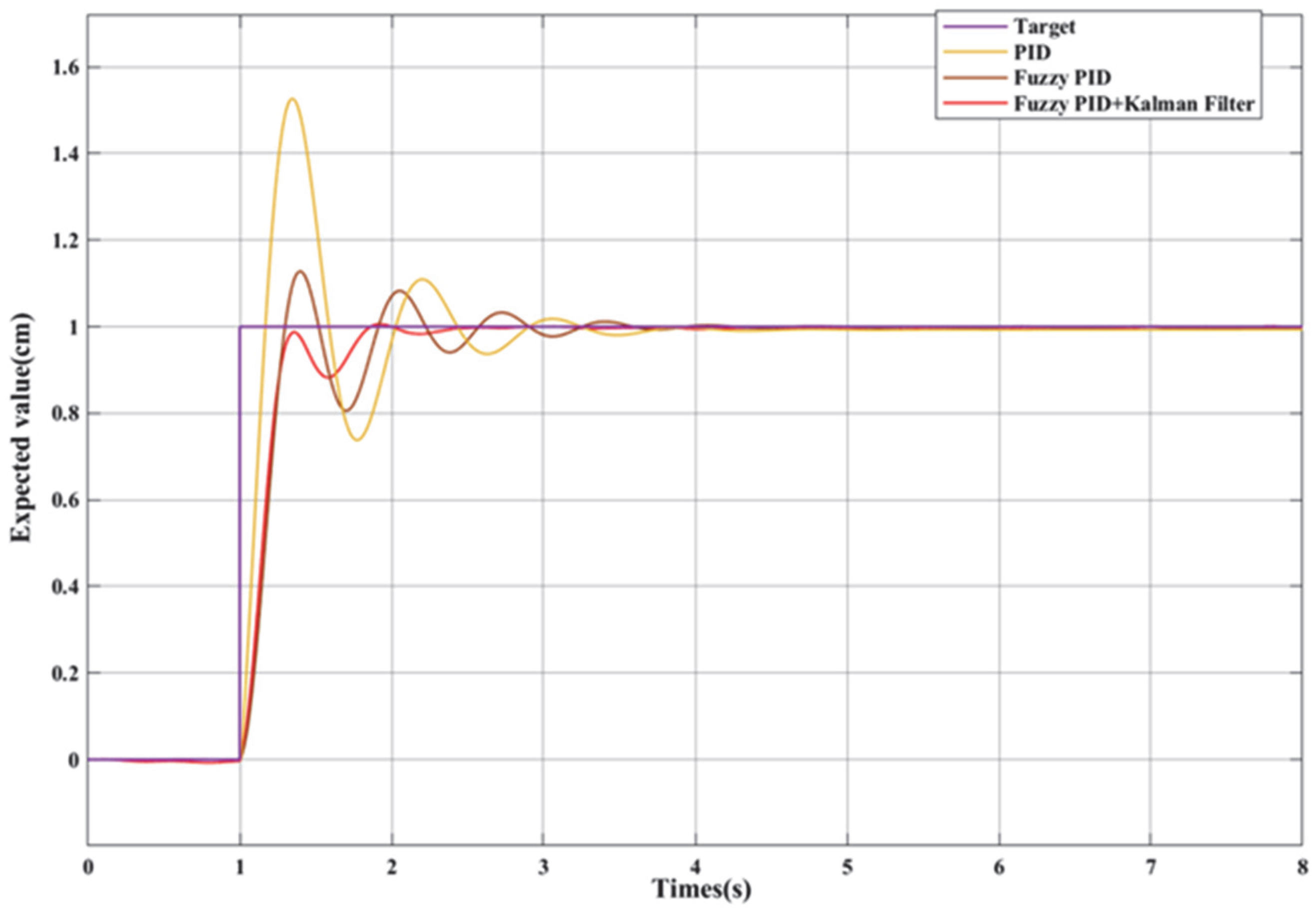
To verify the effectiveness of the designed algorithm, the Simulink software (MATLAB R2024a) is used to build a system model of fuzzy PID and Kalman filter control based on the speed regulation principle of the DC motor. The designed model is shown in Figure 12 Additionally, a simulation comparison was carried out with the ordinary PID and fuzzy PID control algorithms. In the simulation experiment, after multiple tests, the proportionality factors were determined as Kd = 6, Ki = 0.8, and Kp = 12. A step signal with a target value of 1 was added at 1 s. The simulation tracking of the step signal by the three control algorithms is shown in Figure 13
As shown in Figure 13, through the analysis of the adaptive tuning performance of the target signal by the fuzzy PID integrated with Kalman filter, fuzzy PID, and ordinary PID, it can be seen that the control algorithm of the fuzzy PID integrated with Kalman filter has improved by 1 s compared with the fuzzy PID, and by 2 s compared with the ordinary PID. Moreover, its oscillation amplitude during the transition process is small. Therefore, comparatively speaking, the algorithm of the fuzzy PID integrated with Kalman filter has a more rapid deviation correction ability, and the fluctuation during the deviation correction process is small. This proves that the control algorithm proposed in this paper has a fast response speed, can better ensure the stability of the robot during the navigation process, and is suitable for operation in the pigeon farm.

5.2. Experimental Test

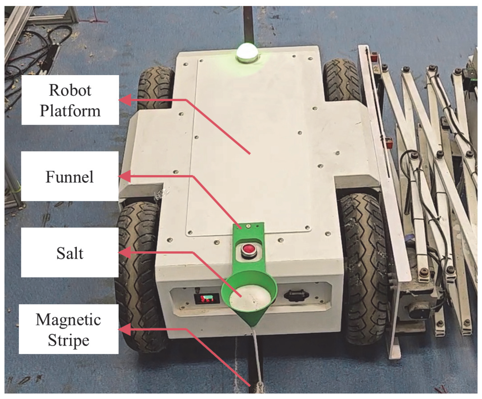
The experimental setup is as follows: A 6 m long, 3 cm wide, and 1.5 mm thick N-pole magnetic strip was selected for the experiment. The strip was placed flat on the ground to replicate actual scenarios by creating straight lines, S-shaped curves, and right-angle turns. The algorithm’s performance improves as deviation decreases. The measurement of magnetic-navigation deviation is as follows: A funnel was mounted at the robot’s tail center to track the magnetic-navigation trajectory. The deviation was calculated based on the path traced by the salt as it dripped from the funnel. Refer to Figure 14 for the experimental setup.
The experimental design is as follows: The study aims to evaluate the operational stability of a robot through autonomous ground navigation experiments employing various algorithms. The experiment involves comparing the efficacy of three algorithms: conventional PID, fuzzy PID, and fuzzy PID combined with a Kalman filter. The experimental procedure includes positioning the robot at the starting point to align with a positioning card, filling the hourglass at the rear center with salt, and maintaining a constant speed of 0.5 m/s. Autonomous navigation tests are conducted on three distinct paths: straight, S-shaped curve, and right-angle turn. The trajectory is recorded using an hourglass dripping method, with the lateral vertical distance between the sand trajectory’s center and the magnetic strip’s center line serving as the actual navigation deviation measurement.

5.3. Results and Discussion

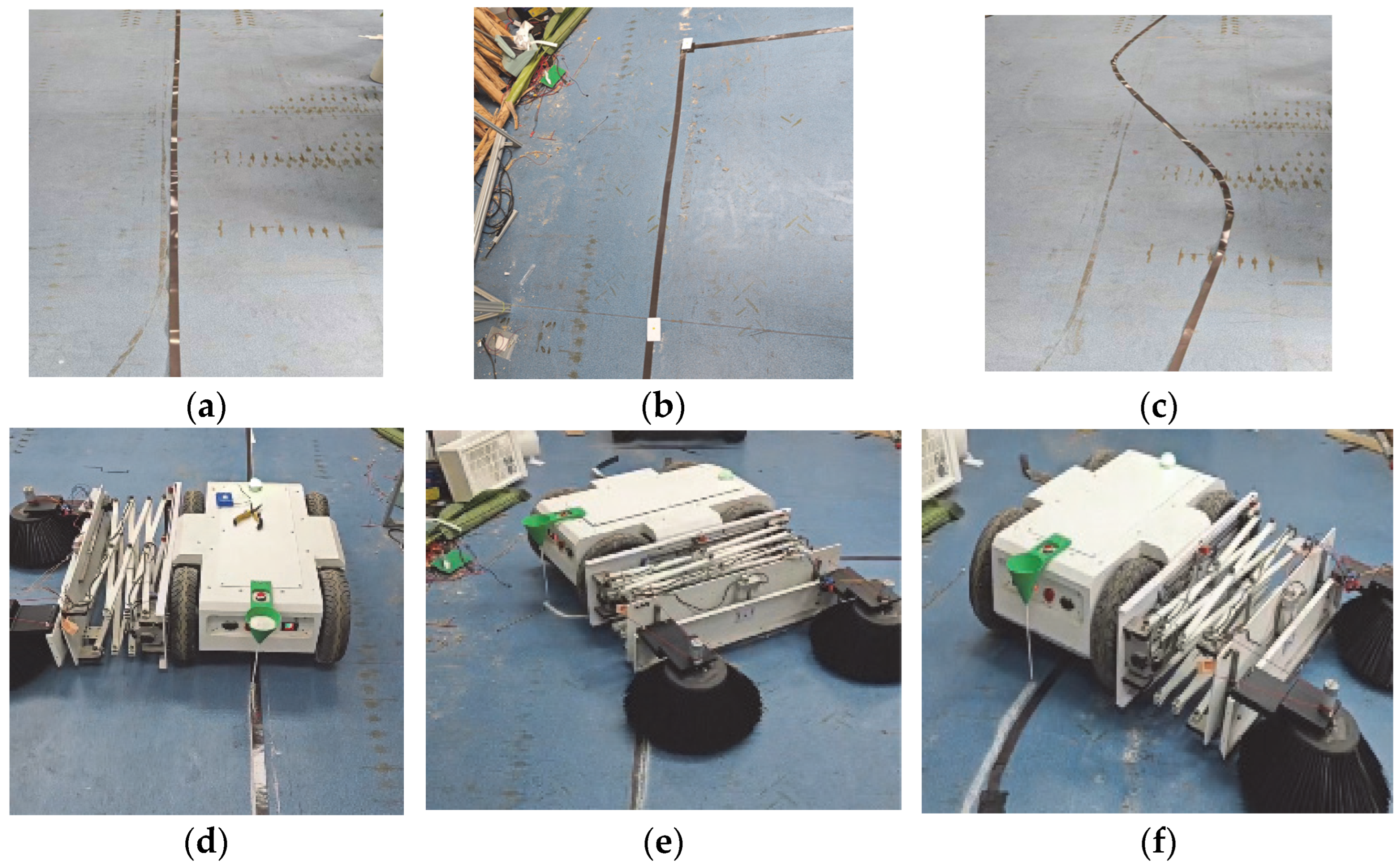
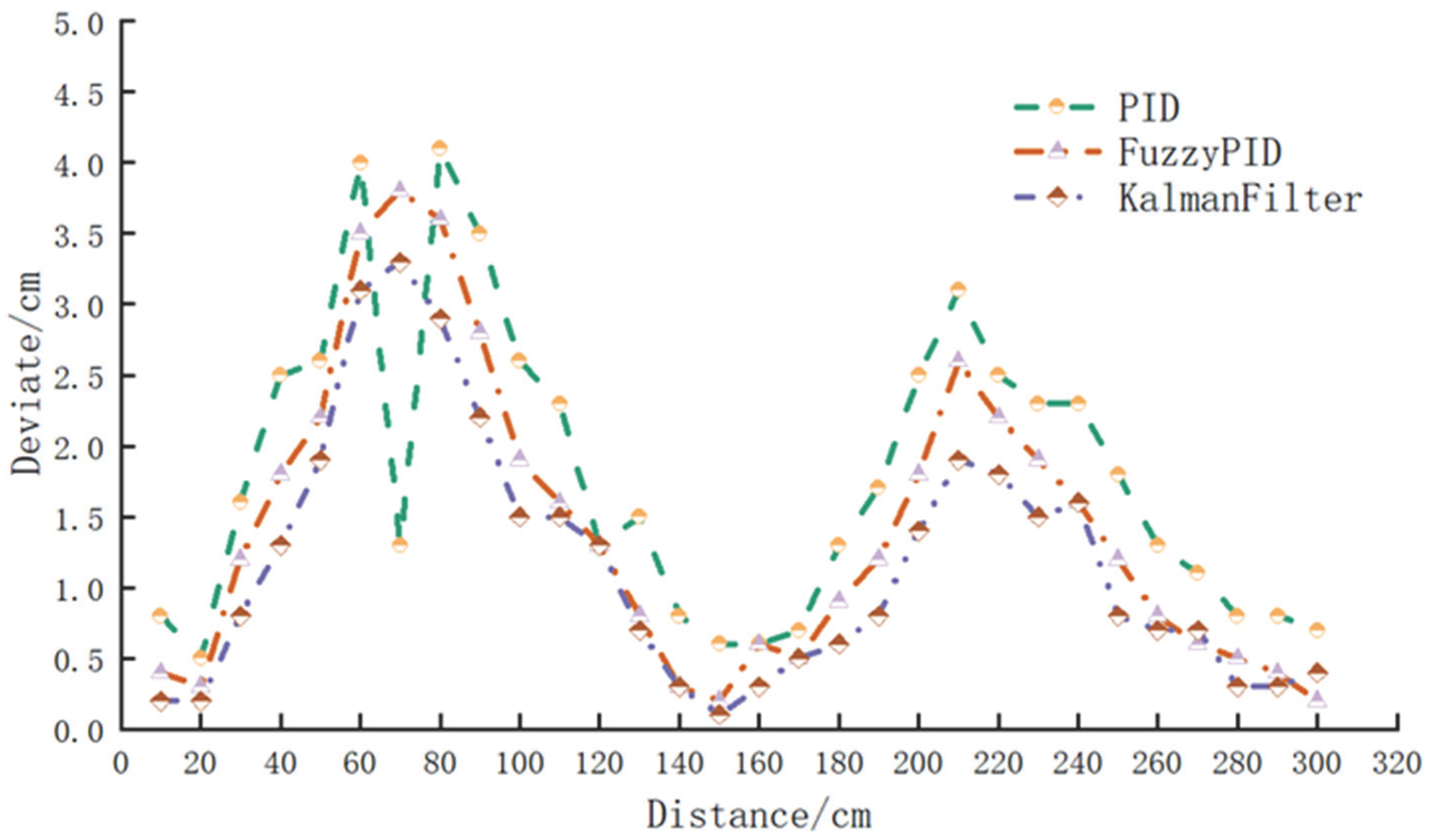
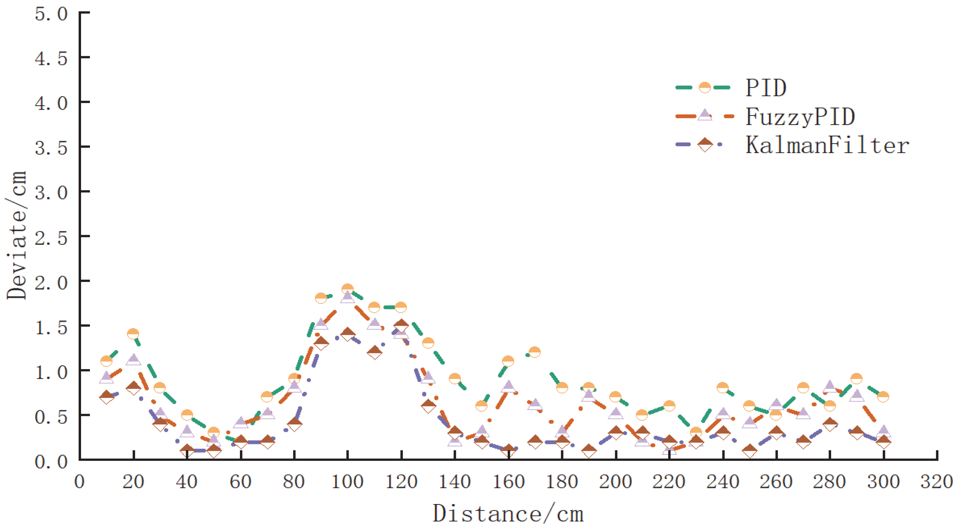
The experiment comprised straight-line navigation, right-angle turn navigation, and S-curve navigation, illustrated in Figure 15. In the straight-line navigation experiment, a passage of 8 m length was utilized for measurement. The lateral distance between the sand track’s center and the magnetic strip’s center was measured at 10 cm intervals, resulting in 30 data points. The absolute values of these measurements were recorded, generating 30 datasets. For the S-curve navigation experiment, an 8 m magnetic strip was shaped into an S-curve, and 30 points were selected to assess the car’s interference resistance during operation. In the right-angle turn navigation experiment, the magnetic strips were configured into right-angle bends, and measurements were taken at 10 cm intervals, yielding 30 sets of experimental data. These outcomes were used to evaluate the robot’s operational stability. Table 2, Table 3 and Table 4 present the deviation values from the three algorithms employed in the straight-line navigation, right-angle turn navigation, and S-curve navigation experiments, respectively. Line graphs created using Origin software (version 2024) are depicted in Figure 16, Figure 17 and Figure 18.
In order to evaluate the performance of the three magnetic-navigation algorithms, we calculated the means and standard deviations of the navigation deviation generated by each algorithm on different types of roads and performed significance tests. The results are shown in Table 5, Table 6 and Table 7.
As shown in Table 5, Table 6 and Table 7, among the three types of road navigation, the algorithm combining Kalman filtering has the smallest mean deviation and standard deviation. Therefore, it can be concluded that this algorithm has high accuracy and strong stability. The P-values obtained from the one-way analysis of variance were all less than 0.05, indicating that the data obtained showed significant differences. As can be easily seen from Figure 16, Figure 17 and Figure 18, during driving on three different types of roads, the deviation produced by the algorithm combining Kalman filtering is significantly smaller than that produced by the other two algorithms. This proved that the algorithm of fuzzy PID combined with the Kalman filter algorithm can effectively reduce magnetic-navigation deviation and improved driving stability. Overall, the designed algorithm has good advanced and practical features.

6. Conclusions

To tackle the harsh, interference-prone environment of pigeon farms, the robot adopts magnetic navigation, and a fusion control algorithm is developed—centered on fuzzy PID for real-time parameter tuning to counter unexpected interferences, while integrating Kalman filtering into the feedback loop to boost signal accuracy—with the goal of enhancing the system’s efficiency and stability. Simulations are conducted in Simulink to verify and compare the performance of different control algorithms, focusing on target signal tracking; results showed that the Kalman filter shortens the adaptive tuning time by nearly 2 s compared to standard PID and by almost 1 s compared to fuzzy PID alone, highlighting the superiority of the proposed fuzzy PID–Kalman filter fusion algorithm. Experimental tests are further carried out to validate practicality under three real-scenario-simulated road conditions (straight lines, S-curves, and right-angle turns), where the magnetic-navigation deviations of the three algorithms are measured; the results demonstrate that the designed fusion algorithm significantly reduces deviation and improves the stability of the robot’s autonomous navigation, confirming its advancement and practicality, thus providing a reference for future research on pigeon farm-cleaning robots.

Author Contributions

Conceptualization, S.H.; methodology, S.H. and H.H.; validation, S.H., H.H. and L.Z.; software, S.H. and H.L.; formal analysis, H.H., X.W. and S.H.; writing—original draft preparation, S.H., Q.Z. and H.H.; formal analysis, S.H., G.C. and H.L.; visualization, X.W., H.L. and S.Z.; supervision, H.H. and Q.Z.; funding acquisition, H.H. All authors have read and agreed to the published version of the manuscript.

Funding

This study was funded by the key Project of Guangzhou Science and Technology Plan (2023B03J0862) and the Guangdong Provincial Special Project for Rural Revitalization Strategy at the Provincial Level (Grant no: YCN(2022) No. 152).

Institutional Review Board Statement

Not applicable.

Data Availability Statement

All data are contained within the article.

Conflicts of Interest

Author Hai Lin was employed by the company Foshan Zhikong Future Technology Co., Ltd. The remaining authors declare that the research was conducted in the absence of any commercial or financial relationships that could be construed as a potential conflict of interest.

References

  1. Hou, C.; Meng, J.; Bian, B. Research, Analysis, and Countermeasure Suggestions on the Development Status of the Pigeon Industry in Nanjing Area. China Anim. Husb. Poult. Breed. 2023, 19, 198–202. [Google Scholar]
  2. Song, Z.; Yang, J.; Gao, X. Large-scale pigeon breeding technology in southern Xinjiang region. Xinjiang Farml. Reclam. Sci. Technol. 2023, 46, 30–34. [Google Scholar]
  3. Zhou, B.; Xie, D.; Chen, S.; Mo, H.; Li, C.; Li, Q. Comparative analysis of SLAM algorithms for mechanical LiDAR and solid-state LiDAR. IEEE Sens. J. 2023, 23, 5325–5338. [Google Scholar] [CrossRef]
  4. Zhou, J.; Geng, S.; Qiu, Q.; Shao, Y.; Zhang, M. A deep-learning extraction method for orchard visual navigation lines. Agriculture 2022, 12, 1650. [Google Scholar] [CrossRef]
  5. Radočaj, D.; Plaščak, I.; Jurišić, M. Global navigation satellite systems as state-of-the-art solutions in precision agriculture: A review of studies indexed in the web of science. Agriculture 2023, 13, 1417. [Google Scholar] [CrossRef]
  6. Huang, Y.; Fu, J.; Xu, S.; Han, T.; Liu, Y. Research on integrated navigation system of agricultural machinery based on RTK-BDS/INS. Agriculture 2022, 12, 1169. [Google Scholar] [CrossRef]
  7. Miao, J.; Niu, P. Design of Path Tracking Control System for Magnetic Navigation AGV. Modul. Mach. Tool Autom. Manuf. Tech. 2021, 09, 107–110+116. [Google Scholar]
  8. Lim, S.; Yook, Y.; Heo, J.P.; Im, C.G.; Ryu, K.H.; Sung, S.W. A new PID controller design using differential operator for the integrating process. Comput. Chem. Eng. 2022, 170, 108105. [Google Scholar] [CrossRef]
  9. Siddique, A.A.; Kim, W.-S.; Kim, Y.-S.; Kim, T.-J.; Choi, C.-H.; Lee, H.-J.; Chung, S.-O.; Kim, Y.-J. Effects of temperatures and viscosity of the hydraulic oils on the proportional valve for a rice transplanter based on PID control algorithm. Agriculture 2020, 10, 73. [Google Scholar] [CrossRef]
  10. Yu, S.; Hao, G. On a Vision-based manipulator simulator. Actuators 2023, 12, 78. [Google Scholar] [CrossRef]
  11. Zhao, C.; Guo, L. PID controller design for second order nonlinear uncertain systems. Sci. China Inf. Sci. 2017, 60, 022201. [Google Scholar] [CrossRef]
  12. Xia, T.; Zhang, Z.; Hong, Z.; Huang, S. Design of fractional order PID controller based on minimum variance control and application of dynamic data reconciliation for improving control performance. ISA Trans. 2022, 133, 91–101. [Google Scholar] [CrossRef]
  13. Yin, M.; Feng, C. Underwater robot motion control based on fuzzy technology. Microcomput. Appl. 2015, 34, 75–77. [Google Scholar]
  14. Li, Y.; Fu, C.; Yang, H.; Li, H.; Zhang, R.; Zhang, Y.; Wang, Z. Design of a closed piggery environmental monitoring and control system based on a track inspection robot. Agriculture 2023, 13, 1501. [Google Scholar] [CrossRef]
  15. Li, S.Y. Fuzzy Control, Neural Control and Intelligent Cybernetics, 2nd ed.; Harbin Institute of Technology Press: Harbin, China, 1998. [Google Scholar]
  16. Yu, Q.; Zhang, X.; Cao, G.; Gong, Y.; Chen, X. Design and Experiment of Electric Control System for Self-Propelled Chinese Herbal Medicine Materials Transplanter. Agriculture 2025, 15, 621. [Google Scholar] [CrossRef]
  17. Zhu, J.; Feng, T.; Kang, S.; Chen, D.; Ni, X.; Wang, L. Design and Simulation of Steering Control Strategy for Four-Wheel Steering Hillside Tractor. Agriculture 2024, 14, 2238. [Google Scholar] [CrossRef]
  18. Zhao, T.; Chen, Y.; Dian, S.; Guo, R.; Li, S. General type-2 fuzzy gain scheduling PID controller with application to power-line inspection robots. Int. J. Fuzzy Syst. 2019, 22, 181–200. [Google Scholar] [CrossRef]
  19. Kodagoda, K.R.S.; Wijesoma, W.S.; Teoh, E.K. Fuzzy speed and steering control of an AGV. IEEE Trans. Control Syst. Technol. 2002, 10, 112–120. [Google Scholar] [CrossRef]
  20. Men, L. Simulation Analysis of Vehicle Four-Wheel Steering Control. Int. J. Sci. Adv. 2023, 4, 259–264. [Google Scholar] [CrossRef]
  21. Liu, K.; Bai, M.; Ni, Y. Two-wheel self-balanced car based on Kalman filtering and PID algorithm. In Proceedings of the 2011 IEEE 18th International Conference on Industrial Engineering and Engineering Management, Changchun, China, 3–5 September 2011; pp. 281–285. [Google Scholar]
  22. Wang, S.; Yang, Y. Quadrotor aircraft attitude estimation and control based on kalman filter. In Proceedings of the 31st Chinese Control Conference, Nanchang, China, 3–5 June 2012; pp. 5634–5639. [Google Scholar]
  23. Filho, L.C.Q.; Filho, J.F.R.; da Silva, N.B.F.; Branco, K.C. Attitude estimation of a simulated flight and GPS positioning with Kalman filter. In Proceedings of the 2015 International Conference on Unmanned Aircraft Systems (ICUAS), Denver, CO, USA, 9–12 June 2015; pp. 742–750. [Google Scholar]
  24. Wu, T.; Bai, R.; Zhu, L.; Qian, Z. Design of a navigation posture reference system based on Kalman filtering. J. Sens. Technol. 2016, 29, 531–535. [Google Scholar]
Figure 1. Pigeon farm environment. (a) Different lighting. (b) Dirt accumulation. (c) Pigeonhole architecture.
Agriengineering 07 00351 g001
Figure 2. Structural diagram of the pigeon farm-cleaning robot: (1) Brush; (2) scissor telescopic mechanism; (3) digital sinking drive motor; (4) telescopic drive motor; (5) power switch; (6) magnetic navigation; (7) card reader; (8) drive tire; (9) indicator light; (10) ultrasonic sensor; (11) touch sensor; (12) Hall sensor.
Agriengineering 07 00351 g002
Figure 3. Schematic diagram of the control system.
Agriengineering 07 00351 g003
Figure 4. Working principle diagram.
Agriengineering 07 00351 g004
Figure 5. Flowchart of the push-broom-system program.
Agriengineering 07 00351 g005
Figure 6. Cleaning navigation path.
Agriengineering 07 00351 g006
Figure 7. Block diagram of the drive module structure.
Agriengineering 07 00351 g007
Figure 8. PID speed control model.
Agriengineering 07 00351 g008
Figure 9. Magnetic-navigation Fuzzy PID control-system model.
Agriengineering 07 00351 g009
Figure 10. Surface plot.
Agriengineering 07 00351 g010
Figure 11. Fuzzy PID-integrated Kalman filter model.
Agriengineering 07 00351 g011
Figure 12. Simulation model of Fuzzy PID integrated with Kalman filter.
Agriengineering 07 00351 g012
Figure 13. Step signal following result diagram.
Agriengineering 07 00351 g013
Figure 14. Experimental platform.
Agriengineering 07 00351 g014
Figure 15. Navigation experiment test. (a) Straight-line. (b) Right-angle. (c) S-curve. (d) Straight-line navigation. (e) Right-angled turn navigation. (f) S-curve navigation.
Agriengineering 07 00351 g015
Figure 16. Line chart of linear deviation values.
Agriengineering 07 00351 g016
Figure 17. Line chart of S-curve driving deviation values.
Agriengineering 07 00351 g017
Figure 18. Line chart of driving deviation values for right-angle turns.
Agriengineering 07 00351 g018
Table 1. Fuzzy control rules for ΔKp, ΔKi, and ΔKd.
ΔKp/ΔKi/
ΔKd
Ec
NBNMNSZOPSPMPB
eNBPB/NB/PSPB/NB/NSPM/NM/NBPM/NS/NMPS/NS/NMZO/ZO/NMZO/ZO/PS
NMPB/NB/ZOPB/NM/NSPM/NS/NMPS/NS/NMPS/NO/ZSZO/PS/NSNS/PS/ZO
NSPM/NM/ZOPM/NM/NSPM/NS/NSPS/ZO/NSZO/PS/NSNS/PM/NSNS/PM/ZO
ZOPM/NM/ZOPM/NS/ZOPS/ZO/ZOZO/PS/ZONS/PS/ZONM/PM/ZONM/PB/ZO
PSPS/ZO/PBPS/ZO/NSZO/PS/PSNS/PS/PSNS/PM/PSNM/PB/PSNM/PB/PB
PMPS/ZO/PBZO/ZO/PMNS/PS/PMNM/PM/PMNM/PM/PSNM/PB/PSNB/PB/PB
PBZO/NB/PSZO/NB/NSNM/NM/NBNM/NM/NBNM/NS/NBNB/ZO/NMNB/ZO/PS
Table 2. Magnetic deviation values for straight-line driving.
Measurement PointPID
Deviation
Fuzzy PID
Deviation
Kalman Filter
Deviation
Measurement PointPID
Deviation
Fuzzy PID
Deviation
Kalman Filter Deviation
11.10.90.7161.10.80.1
21.41.10.8171.20.60.2
30.80.50.4180.80.30.2
40.50.30.1190.80.70.1
50.30.20.1200.70.50.3
60.20.40.2210.50.20.3
70.70.50.2220.60.10.2
80.90.80.4230.30.20.2
91.81.51.3240.80.50.3
101.91.81.4250.60.40.1
111.71.51.2260.50.60.3
121.71.41.5270.80.50.2
131.30.90.6280.60.80.4
140.90.20.3290.90.70.3
150.60.30.2300.70.30.2
Table 3. Magnetic deviation values for S-shaped curve driving.
Measurement PointPID
Deviation
Fuzzy PID
Deviation
Kalman Filter DeviationMeasurement PointPID
Deviation
Fuzzy PID
Deviation
Kalman Filter Deviation
10.80.40.2160.60.60.3
20.50.30.2170.70.50.5
31.61.20.8181.30.90.6
42.51.81.3191.71.20.8
52.62.21.9202.51.81.4
64.03.53.1213.12.61.9
71.33.83.3222.52.21.8
84.13.62.9232.31.91.5
93.52.82.2242.31.61.6
102.61.91.5251.81.20.8
112.31.61.5261.30.80.7
121.31.31.3271.10.60.7
131.50.80.7280.80.50.3
140.80.30.3290.80.40.3
150.60.20.1300.70.20.4
Table 4. Magnetic deviation values for right-angle bends.
Measurement PointPID
Deviation
Fuzzy PID
Deviation
Kalman Filter DeviationMeasurement PointPID
Deviation
Fuzzy PID
Deviation
Kalman Filter Deviation
10.90.50.2161.50.90.6
20.80.60.2172.92.21.8
30.80.50.3183.73.12.5
40.70.30.4193.32.82.3
51.30.90.6202.51.60.8
61.51.10.7211.61.20.8
71.31.30.9221.50.90.7
81.61.20.8231.30.80.8
91.30.90.8240.90.60.5
101.40.80.5250.80.30.2
110.50.20.3260.60.50.3
122.63.02.8270.50.70.4
133.72.82.7280.30.50.2
142.31.51.6290.80.60.2
151.30.50.3300.90.80.3
Table 5. Analysis of linear navigation data.
AlgorithmSample SizeMeanStandard Deviation
PID300.890.082
Fuzzy PID300.650.080
Kalman300.430.074
Table 6. Analysis of right-angle bend navigation data.
AlgorithmSample SizeMeanStandard Deviation
PID301.500.173
Fuzzy PID301.120.152
Kalman300.850.143
Table 7. S-curve navigation data analysis.
AlgorithmSample SizeMeanStandard Deviation
PID301.780.188
Fuzzy PID301.420.191
Kalman301.160.162
Disclaimer/Publisher’s Note: The statements, opinions and data contained in all publications are solely those of the individual author(s) and contributor(s) and not of MDPI and/or the editor(s). MDPI and/or the editor(s) disclaim responsibility for any injury to people or property resulting from any ideas, methods, instructions or products referred to in the content.