Article

Theoretical Study of a Pneumatic Device for Precise Application of Mineral Fertilizers by an Agro-Robot

1
Institute of Forestry and Engineering, Estonian University of Life Sciences, 56 Kreutzwaldi Str., 51006 Tartu, Estonia
2
Department of Operation and Technical Service of Machines, Dmytro Motornyi Tavria State Agrotechnological University, 66 Zhukovsky Str., 69600 Zaporizhzhia, Ukraine
*
Authors to whom correspondence should be addressed.
AgriEngineering 2025, 7(10), 320; https://doi.org/10.3390/agriengineering7100320
Submission received: 20 June 2025 / Revised: 19 September 2025 / Accepted: 23 September 2025 / Published: 1 October 2025
(This article belongs to the Section Agricultural Mechanization and Machinery)

Abstract

This article presents the development of a new pneumatic device for the precise application of mineral fertilizers, designed for use in precision agriculture systems involving farming robots. The proposed device is mounted on an autonomous agricultural platform and utilizes a machine vision system to determine plant coordinates. Its operating principle is based on accumulating a single dose of fertilizer in a chamber and delivering it precisely to the plant’s root zone using a directed airflow. The study includes a theoretical investigation of fertilizer movement inside the applicator tube under the influence of airflow and rotational motion of the tube. A mathematical model has been developed to describe both the relative and translational motion of the fertilizer. The equations, which account for frictional forces, inertia, and air pressure, enable the determination of optimal structural and kinematic parameters of the device depending on operating conditions and the properties of the applied material. The use of numerical methods to solve the developed mathematical model allows for synchronization of the device’s operating time parameters with the movement of the agricultural robot along the crop rows. The obtained results and the developed device improve the accuracy and speed of fertilizer application, minimize fertilizer consumption, and reduce soil impact, making the proposed device a promising solution for precision agriculture.

1. Introduction

Modern machines primarily use disk centrifugal working units for uniform fertilizer distribution across the entire field surface. In row-based applications, fertilizer tubes attached to the tines of soil-cultivating implements are used, allowing fertilizers to be placed in the soil as a strip or band [1,2]. However, both methods fail to deliver a differentiated fertilizer dose precisely to the root zone of each plant, which is essential for precision agriculture [3,4,5].
In these approaches, the metering device operates continuously during motion, and the application rate is expressed in kg ha−1. For perennial plantations such as orchards and berry fields, however, the agronomic requirement is different: fertilizers should be applied to plants rather than to the whole field, and the unit of dosage becomes kg per plant. In this case, fertilizer must be delivered in discrete doses directly under the plant canopy rather than in a continuous flow between crop rows. To address this issue, we propose a modular fertilizer application machine that will be mounted on an unmanned agricultural power unit and designed to achieve targeted fertilizer delivery.
Compared to conventional fertilization methods, broadcasting and banding–localized and precise application of mineral fertilizers offer significant environmental advantages. Broadcasting ensures high productivity but often leads to excessive soil fertilization, nutrient losses through leaching, and increased weed growth, negatively affecting the environment and fertilizer use efficiency. Banding reduces some of these losses but still applies fertilizer not only to the plant but also to the inter-row space. In contrast, localized and dose-controlled application directly to the root zone minimizes nutrient losses, reduces the risk of soil and water contamination, limits weed growth, and thus decreases the need for herbicides, enhancing the environmental sustainability of the technology. Potential drawbacks include the need for more complex technical solutions and higher energy consumption for robotic systems; however, these are offset by increased accuracy, reduced overall fertilizer use, and positive environmental impact.
The conducted analysis revealed that some agricultural machines also utilize airflow to deliver fertilizers to the application zone [6,7,8]. A known example is a pneumatic seeder for subsurface fertilizer application [9], which includes a frame with a mounted hopper. The lower part of the hopper has openings equipped with metering devices, beneath which ejectors are installed. The ejectors’ confusors are connected via air ducts to the blower outlet of a fan, while their diffusers, through material-conveying tubes, direct fertilizers into the soil. The axes of the ejectors are aligned with the coulter pipe outlets, and the confusor diameter exit openings increase proportionally to the angles between the ejector axes and vertical planes parallel to the seeder’s movement direction.
The drawbacks of this machine, particularly for use in orchards and berry fields, include its considerable weight, large width, disturbance of the turf cover, and its trailed aggregation method [10,11,12]. Another known method is pneumatic transportation for applying granular mineral fertilizers [13], which utilizes compressed air in a pneumatic pipeline to transport fertilizers from a hopper through a material-conveying pipe to the application zone in the soil. The fertilizers are transported through the material-conveying pipe at an angle greater than the friction angle between the fertilizer granules and the inner surface of the pipe, ensuring the initiation of fertilizer movement at the transition from the material-conveying pipe to the pneumatic pipeline at a velocity matching that in the material-conveying pipe. In this system, the fertilizers are accelerated by the accompanying airflow, but it does not eliminate free-flight phase from the end of the fertilizer tube to the soil surface, which can lead to dispersion [14,15,16,17,18]. Additionally, this method can reduce energy consumption required for material transportation.
However, this method also has drawbacks. Fertilizers are supplied from the hopper through a material-conveying pipe at a specific angle to the pneumatic pipeline, which is positioned at a small angle to the horizontal. This design does not eliminate the risk of clogging when using different types of fertilizers or when their moisture content increases. Additionally, this method does not allow for precise dosing and portioned delivery of fertilizers at a specific moment in time to an individual plant. In other words, all known pneumatic spreaders work in a permanent airflow mode, while the requirement in berry plantations is a cyclical process: first, the prescribed portion must be measured and only then rapidly ejected to the target location beneath the plant canopy. Without such plant-wise dosing, fertilizer is wasted on weeds, crop care becomes more difficult, and both ecological and economic efficiency are reduced.
In recent years, several studies have addressed the challenges of automation and precision in fertilizer application. The paper in [19] presents Agrobot Gari, a multimodal robotic platform for blueberry management, which performs soil sampling, weed spraying, and plant-status monitoring, but it does not provide granular plant-wise fertilizer dosing or pneumatic timing and steering. A review of pneumatic centralized fertilizer discharge systems analyzes the main mechanical components, such as metering units, air–fertilizer mixers, and distributors, focusing on continuous airflow designs, distribution uniformity, and anti-clogging considerations [20]. Another review of precision fertilizer application technologies summarizes actuator innovations and sensing-to-actuation control, reporting centimeter-level placement accuracy in seedling crops, but this still emphasizes continuous or row-wise application paradigms [21]. In contrast, the proposed device ensures plant-specific discrete dosing (kg per plant) by combining accumulation of a defined dose with rapid pneumatic ejection, synchronized with tube orientation and valve timing on a lightweight agro-robot.
Since there are currently no designs or technical solutions that ensure high-quality and rapid mineral fertilizer application using an agricultural robot in precision farming, this research topic is highly relevant and important for the field of agricultural machinery engineering and the efficient use of mechanized systems. The novelty of the proposed device lies in this two-stage principle: accumulation of a defined dose followed by fast, oriented ejection and its integration with the robot’s perception and actuation system for synchronized operation.
The aim of the research was to increase the efficiency of the developed pneumatic device for precise mineral fertilizer application using an agricultural robot by theoretically substantiating its optimal structural and kinematic parameters. The work is limited to theoretical modeling as a necessary first step; subsequent experimental validation on a benchtop rig and robotic platform will be addressed in follow-up research.

2. Materials and Methods

2.1. Device Description

For the precise fertilizer application operation during plant care (Figure 1), a wheeled farming robot (1) is used, equipped with a modular fertilizer application device (2). The farming robot (1) moves at a constant speed V m along the crop row, while the treated plants (3) are positioned within its inter-wheel space.
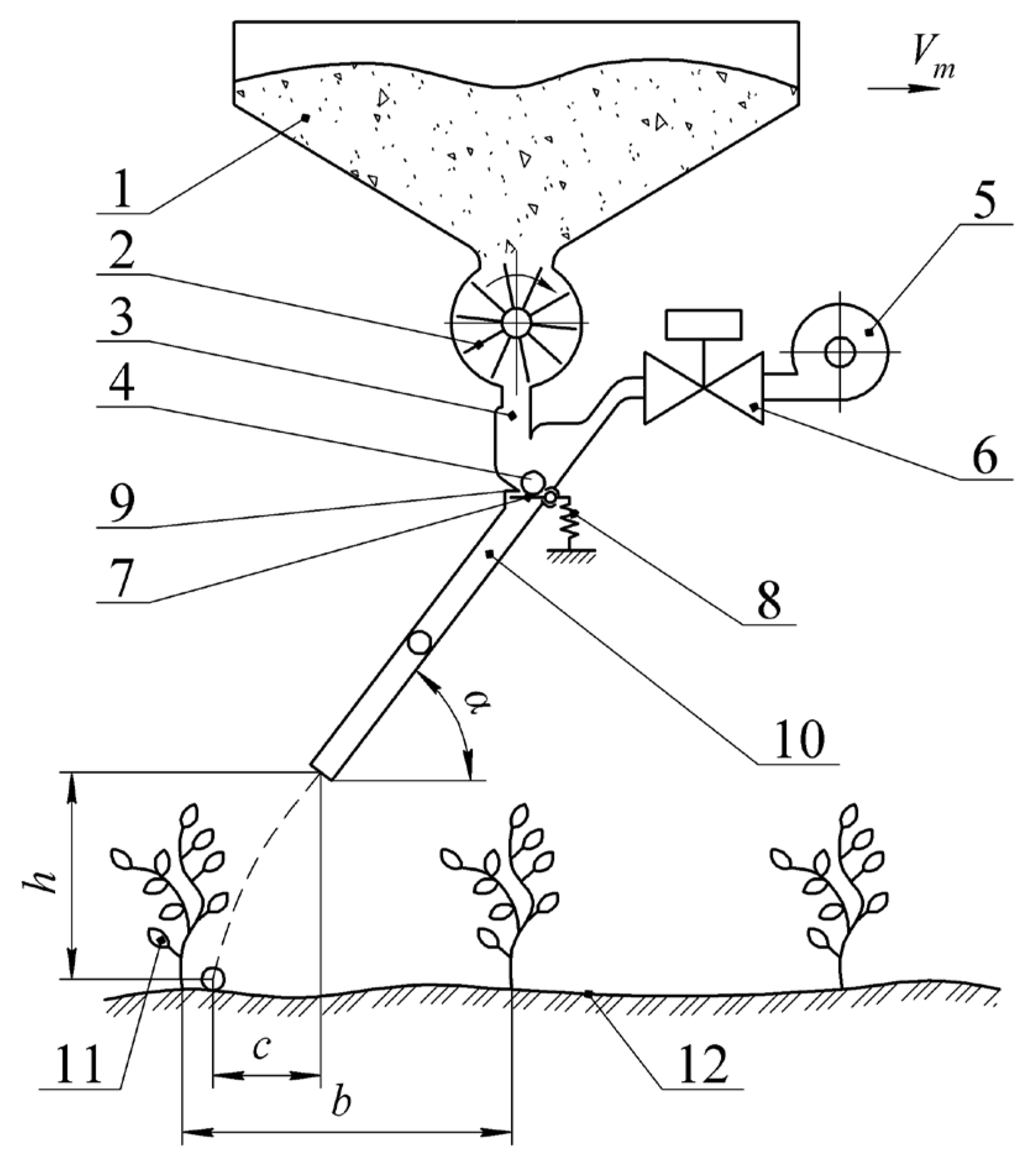
A more detailed schematic of the proposed fertilizer application device is shown in Figure 2.
The operating principle of the device is as follows: as the farming robot moves, fertilizers are dispensed from the hopper (1) using the metering unit (2) into the accumulation chamber (3), where a single dose of fertilizer (4) is collected. The longitudinal coordinate of the treated plant (11) within the farming robot’s inter-wheel space is determined. A logical extension of this work is the integration of machine vision systems for real-time perception and control. Our group has already initiated research in this area [22], and it has been identified as a priority for future studies. The applicator tube (10), inclined at an angle α to the horizontal, is automatically directed toward the plant’s root zone. At the precise moment, the solenoid valve (6) is activated. The compressed air source (5) generates an airflow, which enters the accumulation chamber (3), overcomes the spring tension (8) of the valve (7), captures the accumulated fertilizer dose (4), and transports it through the applicator tube (10) directly to the root zone of the plant (11). The outlet end of the applicator tube is positioned at a height h above the soil surface (12). After the fertilizer is applied, the valve (7) is pressed against the restrictive surface (9) by the spring (8), and the working cycle is repeated.
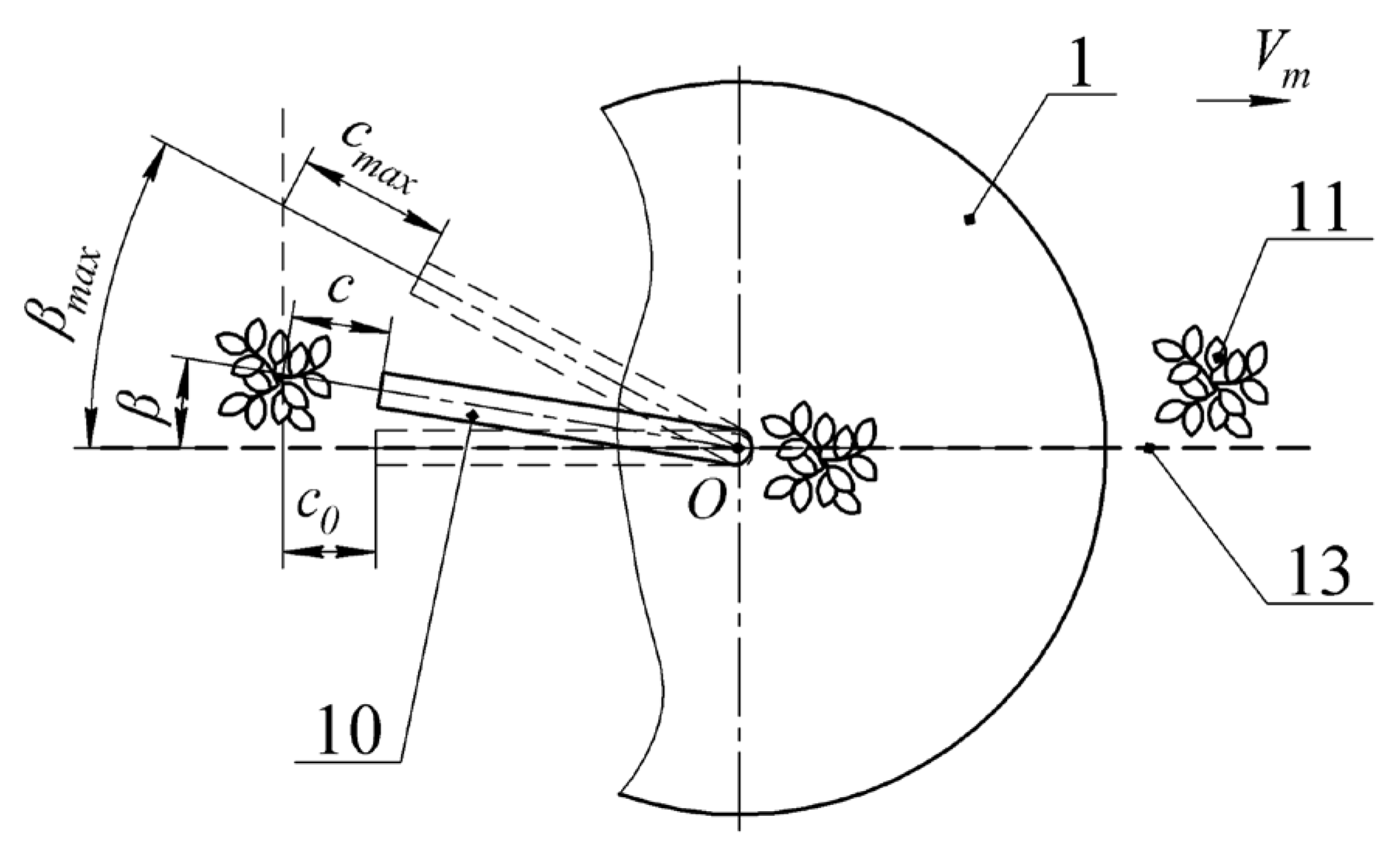
To optimize the route of the farming robot (1) (Figure 3) during movement, its control system, which can be based on data obtained from the front camera, directs it along the conditional row line (13) using the front steerable wheels. To determine the movement vector, 3 to 5 nearest plants are taken into account, while also evaluating the distance b between neighboring plants in the row. To recognize individual plants, it is advisable to use machine vision [22]. This is necessary to synchronize the timing and duration of the opening of the air valve. Since in field conditions the treated plants are often shifted from the conditional row line, steering the entire farming robot (1) toward each individual plant is inefficient and leads to unproductive time losses. Therefore, it becomes necessary to move the end of the applicator tube (10) within the inter-wheel space by a certain angle β , which varies within a range from 0 to β max (a maximum value). When the angle β changes, the horizontal projection of the distance c (Figure 2) that the fertilizer particle (4) travels from the applicator tube (10) to the root zone of the plant also changes. Since the distance c changes with the angle β and directly depends on the ejection speed of the fertilizer particle from the applicator tube, it is necessary to adjust the duration of the air valve opening to ensure that the fertilizer accurately reaches the plant’s root zone.
Since the time required for the farming robot to travel the distance between two plants is 1.5 to 2.5 s, and the entire process occurs while the robot is in continuous motion, the fertilizer must be applied within a very short time frame.
Therefore, it is necessary to develop a mathematical model describing the movement of the fertilizer particle (4) through the inclined tube (10) under the influence of the airflow from the compressed air source (5). This model should establish the relationship between the opening time t of the solenoid valve 6 and the travel time t m of the fertilizer particle (4) to the soil surface, taking into account the rotation angle β of the applicator tube (10).
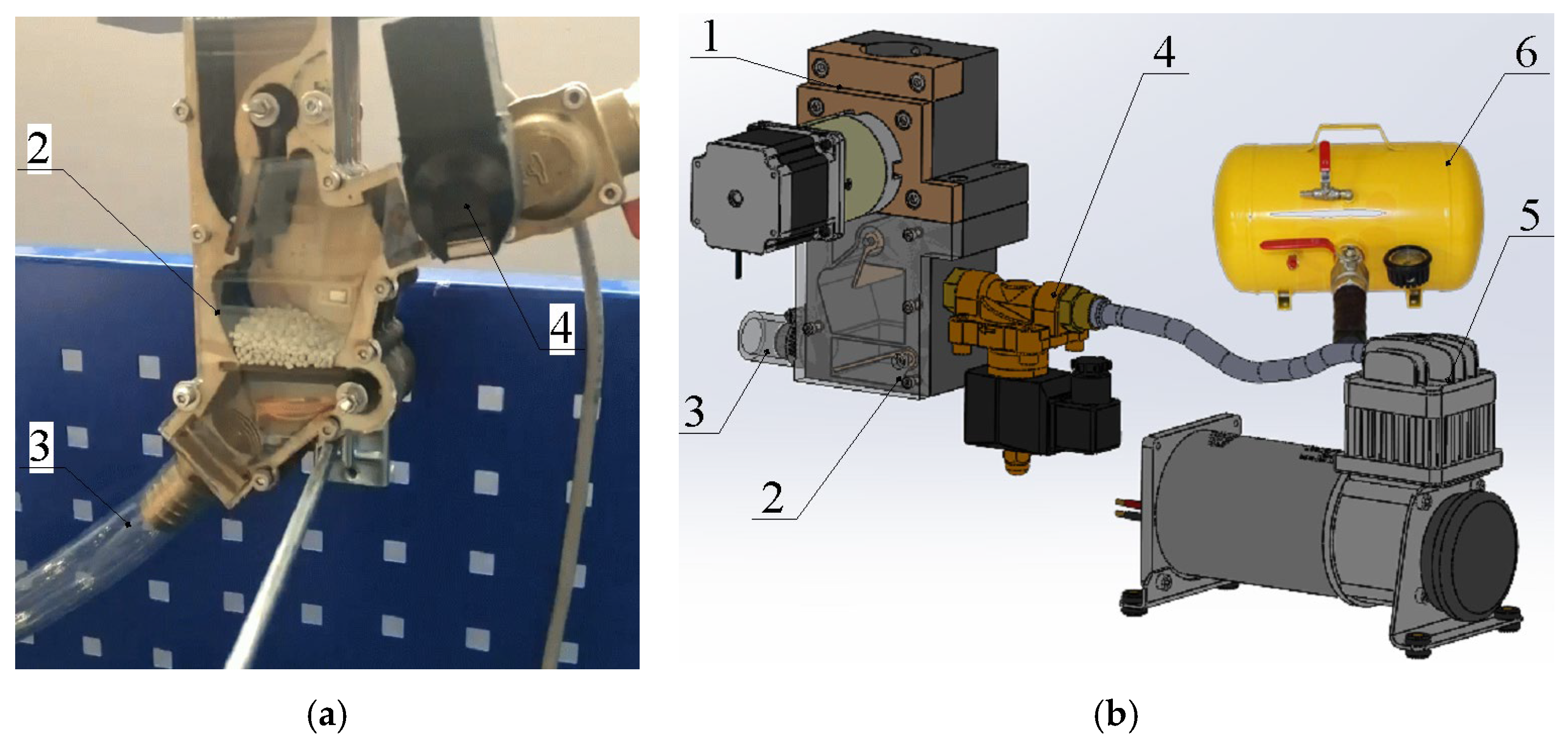
The general view and 3D model of the developed prototype of the mineral fertilizer applicator with pneumatic system elements are shown in Figure 4.
The prototype was equipped with a fertilizer pipe of 0.019 m inner diameter, a maximum fertilizer dose capacity of 0.04 kg, an Air-Zenith 2nd Gen. 200PSI AZOB2 compressor (Air-Zenith, Las Vegas, NV, USA) with an airflow rate of 2 L s−1, and a 10 L air receiver.
The developed device belongs to the field of agricultural engineering, specifically to machines used for localized mineral fertilizer application in precision farming systems.

2.2. Mathematical Model

Since the movement of the fertilizer portion M occurs along the inclined tube, and the tube itself rotates at a certain angle β , the fertilizer portion M performs a complex motion: relative motion along the tube and translational motion with the tube. Therefore, the absolute motion of the fertilizer portion, as is known, will represent the geometric sum of the relative and translational movements [23].
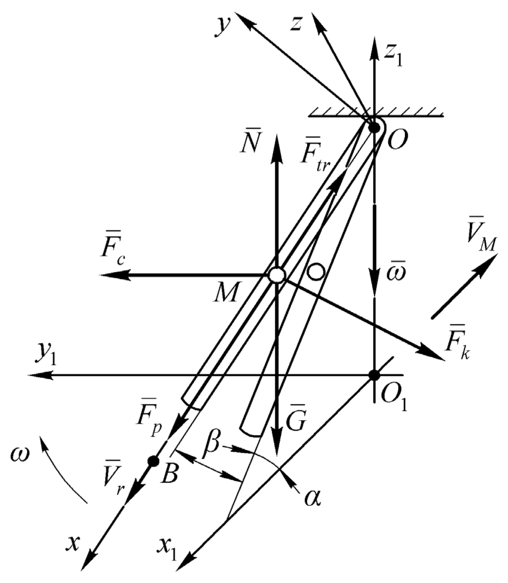
First, we will set up the differential equations for the relative motion of the fertilizer portion M along the tube. To do this, we need to build an equivalent diagram of all the forces acting on the fertilizer portion during relative motion and choose the necessary coordinate systems (Figure 5).
First, we will choose an absolute spatial Cartesian coordinate system O 1 x 1 y 1 z 1 , in which the axis O 1 x 1 is directed along the row line of plants, against the movement direction of the farming robot, the axis O 1 y 1 is perpendicular to the O 1 x 1 -axis and directed to the left relative to the movement of the robot, and the axis O 1 z 1 is vertical. The origin of the absolute coordinate system (point O ) is located on the row axis, with the suspension point O of the inclined tube located on the O 1 z 1 -axis (Figure 5).
In the coordinate system O 1 x 1 y 1 z 1 , the inclined tube is shown at an angle α to the horizon, with a fertilizer portion M located inside it at an arbitrary moment in time. The tube itself is deflected from its initial position (from the O 1 x 1 -axis) by an arbitrary angle β , which changes within the range from 0 to β max , where β max is defined as the maximum deviation of the plants from the row axis.
In the initial position, the tube is located in the plane x 1 O 1 z 1 . The angle β is measured from the O 1 x 1 -axis to the O 1 y 1 -axis. The end of the inclined tube describes a trajectory that is an arc of a circle, with the center located on the O 1 z 1 -axis, and the radius equal to L cos α , where is the length L of the tube.
Next, we will choose a relative Cartesian coordinate system O x y z , rigidly attached to the tube. The origin of this coordinate system (point O) is located on the O 1 z 1 -axis at the suspension point of the inclined tube to the accumulation chamber. The O x -axis is directed along the longitudinal axis of the tube, in the direction of the movement of the fertilizer portion. The O z -axis lies in the vertical plane that passes through the longitudinal axis of the tube and is directed perpendicular to the O x -axis and upward. The O y -axis is perpendicular to the plane x O z , directed towards the rotation of the tube.
As shown in the equivalent diagram (Figure 5), during the movement of the fertilizer portion M inside the tube, the following forces act on the fertilizer portion [24].
The weight G of the fertilizer portion, directed vertically downward, is given by:
G = m g ,
where m —is the mass of the fertilizer portion; g —is the gravitational acceleration.
The centrifugal force of inertia F ¯ c , directed along the radius of the arc described by the point where the fertilizer portion M is located inside the tube at a given moment in time t , is in the horizontal plane, i.e., perpendicular to the O 1 z 1 -axis of rotation of the inclined tube:
The magnitude of this force is given by:
F c = m x cos α ω 2 .
where x —is the coordinate of the point where the fertilizer portion M is located on the axis O x at any given time t ; ω —is the angular velocity of the tube’s rotation.
Since the tube’s translational motion is rotational, the fertilizer portion M is acted upon by the Coriolis inertial force F ¯ k , which is perpendicular to the plane formed by the vectors ω ¯ and V ¯ r (plane x O z 1 ), and directed to the left along the path of fertilizer movement in the inclined tube. As is known, this force is determined by the following expression:
F ¯ k = 2 m ω ¯ × V ¯ r ,
where V ¯ r —the relative movement velocity of the fertilizer portion M in the tube.
The magnitude of this force will be equal to:
F k = 2 m V r ω cos α .
Considering that V r = x ˙ , expression (4) takes the following form:
F k = 2 m x ˙ ω cos α .
Next, as the fertilizer portion moves along the tube, it experiences a frictional force F ¯ t r directed opposite to the vector V ¯ r , which, as is known, is determined by expression:
F t r = f N .
where f —the coefficient of sliding friction; N —the normal reaction from the inner surface of the tube.
At the same time, the normal reaction N arises due to the action of forces G ¯ , F ¯ c and F ¯ k . As can be seen from the presented force scheme and the above:
N = F c sin α G cos α 2 + F k ,
or, considering expressions (1), (2), and (5), we get:
N = m x ω 2 cos α sin α g cos α 2 + 4 x ˙ 2 ω 2 cos 2 α .
Substituting expression (8) into (6), we will have:
F t r = f m x ω 2 cos α sin α g cos α 2 + 4 x ˙ 2 ω 2 cos 2 α .
Finally, the fertilizer portion experiences the force F ¯ p of the airflow, which is the primary driving force, directed along the longitudinal axis of the inclined tube (along the O x -axis). The value of this force primarily determines the time it takes for the fertilizer portion to move along the inclined tube and, ultimately, the time it takes for the portion to reach the root zone of the specific plant.
By changing the value of this force in the equation of motion for the fertilizer portion, we can obtain the desired values for the time it takes the fertilizer to reach its destination.
Based on the developed force diagram acting on the fertilizer portion as it moves through the inclined tube, we can write the required equation of motion in vector form:
m a ¯ = G ¯ + F ¯ c + F ¯ k + N ¯ + F ¯ t r + F ¯ p ,
where a ¯ —the acceleration of the fertilizer portion M as it moves through the inclined tube.
In projection onto the O x -axis (the longitudinal axis of the inclined tube), the required equation of motion takes the following form:
m x ¨ = G sin α + F c cos α F t r + F p .
Then, taking into account (1), (2), (5), (9), and dividing both the left and right sides of Equation (11) by mass m , we will have a differential equation of the following form:
x ¨ = g sin α + x cos 2 α ω 2 f x ω 2 cos α sin α g cos α 2 + 4 x ˙ 2 ω 2 cos 2 α + F p m .
The differential Equation (12) is the equation of relative motion of the portion of fertilizer along the inclined tube. This is a second-order differential equation, it is nonlinear, and it can only be solved using numerical methods.

2.3. Mathematical Model Analyzes

The initial conditions for the differential Equation (12) are as follows:
at   t   =   0 :   x = x 0 = 0 ;   x ˙ = x ˙ 0 =   0 .
The solution to Equation (12) should be carried out until the value of x = L , where L is the length of the inclined tube. The time t 1 , at which the displacement x of the fertilizer portion reaches x = L , will be the time of flight of the fertilizer from the inclined tube. The relative velocity V r 1 = x ˙ t 1 represents the speed at which the fertilizer portion exits the tube. By setting different values for the force F ¯ p of the air flow, various values for the time t 1 and velocity V r 1 can be obtained based on Equation (12).
However, during the time t 1 that the fertilizer portion exits the inclined tube, it must deviate from the O 1 x 1 axis towards the O 1 y 1 axis by an angle β , where the angle β is such that the projection of the tube onto the horizontal plane lies along the line connecting point O 1 with the location of the plant. Therefore, the time t 1 for the fertilizer portion to exit the tube must be coordinated with the time t p for the tube to rotate by the angle β , and it must be equal to t 1 . If the angular velocity ω of the tube’s rotation by angle β is assumed to be constant, it should be equal to ω = β t 1 radians per second.
On the other hand, t 1 appears in expression (12), from where the time of fertilizer exit from the tube is determined. The coordination of the time for the fertilizer portion to exit the tube and the time for the tube to rotate by angle β can be carried out as follows.
Since the time taken to pass the distance between two plants is 1.5 to 2.5 s, we start by assuming t p 0 = 2.0 s, the midpoint of the interval 1.5…2.5 s. We then substitute the value ω = β t p 0 into Equation (12). After performing the calculations with Equation (12), we obtain the calculated value t 1 1 and compare it with the initially assumed t p 0 = 2.0 s. If t 1 1 t p 0 , we proceed with the next calculation, replacing t p 0 with a new value: t p 1 = t p 0 + Δ , where Δ is the step size for the parameter change, and we substitute ω = β t p 1 into Equation (12). After the recalculation, the obtained value t 1 2 is compared with t p 1 .
If t 1 2 t p 1 < t 1 1 t p 0 , we continue increasing t 1 by Δ , meaning we set: t p 2 = t p 1 + Δ . Otherwise, if the condition is not met t 1 2 t p 1 > t 1 1 t p 0 , we decrease t 1 by Δ , meaning we set: t p 2 = t p 0 Δ .
Thus, at some k-th step, we obtain the calculated value | t 1 k t p , k 1 | 0 . The calculated value t 1 k can be considered the coordinated time for the rotation of the tube by angle β and the time of flight of the portion of fertilizer from the tube.
Another algorithm can also be applied to coordinate the time t 1 of the fertilizer portion’s flight from the tube and the time for the tube to rotate by angle β , using a simplified mathematical model derived from Equation (12), assuming a constant value for ω = 0 . Then, from expression (12), we get:
x ¨ = g sin α f g cos α + F p m .
Solving Equation (13) gives us some value t 1 = t p 0 for the time of flight of the portion of fertilizer from the tube. Next, we determine ω = β t p 0 and substitute this value of ω into Equation (12). After solving it, we get the value t 1 1 . If t 1 1 t p 0 0 , then we accept the value of the time of flight t 1 = t 1 1 . If t 1 1 t p 0 0 , we set: t p 1 = t p 0 + Δ , where Δ is the step size for the parameter change. We then determine ω = β t p 1 , substitute it into Equation (12), and get t 1 2 . If t 1 2 t p 1 0 , we accept t 1 2 as the agreed-upon time.
If t 1 2 t p 1 0 and at the same time t 1 2 t p 1 < t 1 1 t p 0 , we set: t p 2 = t p 1 + Δ . We determine ω = β t p 2 and continue the calculation using Equation (12) until: t 1 k t p , k 1 0 . In this case, we accept t 1 k as the agreed-upon time.
If t 1 2 t p 1 t 1 1 t p 0 , we set: t p 1 = t p 0 Δ , which means moving in the opposite direction, until a certain k is reached, for which the equality t 1 k t p , k 1 0 holds. The resulting value t 1 k is then accepted as the agreed-upon time.
Thus, the time of flight will be: t 1 = t 1 k .
Next, in the translational motion, after being deflected by the angle β from the axis O 1 x 1 , the tube will be positioned on the segment OB (Figure 5), where B is the plant location. In this position, the distance from the tube end to the plant will be: C = O B L . In the first approximation, we can assume that the flight time of the fertilizer portion from the moment of departure from the tube will be: t 2 = C V r 1 = O B L V r 1 , where V r 1 is determined when t 1 = t 1 k .
If the distance C 0 is given from the end of the tube horizontal projection to the plant in the row, then when the tube is deflected by an angle β from axis O 1 x 1 , this distance increases and becomes C 0 cos β . The actual distance C from the tube end to the plant will be: C = C 0 cos β cos α .
Thus, the time for fertilizer portion M to move from accumulation chamber to the plant, deflected by angle β relative to the row (axis O 1 x 1 ), is: t 1 + t 2 . If β = β max , then: C = C 0 cos β max cos α .
In the proposed algorithms for coordinating fertilizer ejection time t 1 from the inclined tube with tube’s rotation by angle β max , β should be replaced by β max .

2.4. Methodology for Verifying the Adequacy of Theoretical Studies

To verify the adequacy of the developed mathematical model of mineral fertilizer portion movement through an inclined tube, preliminary experimental studies were carried out to measure the transit time of fertilizer portions weighing 0.01 kg and 0.04 kg through a tube with a diameter of 0.019 m and a length of 1 m, installed at an angle of 45° to the horizontal. The transit time was recorded at distances of 0.33, 0.66, and 1.0 m from the tube inlet using a chronograph. Each experiment was repeated five times. The experimental results were used to evaluate the accuracy of the mathematical model and to confirm its adequacy.
The obtained experimental transit time data were compared with the results of the numerical solution of the differential equation describing particle motion in the tube. To assess model accuracy, graphical dependencies of fertilizer portion displacement over time were constructed, and the correlation between theoretical and experimental values was calculated.

3. Results and Discussion

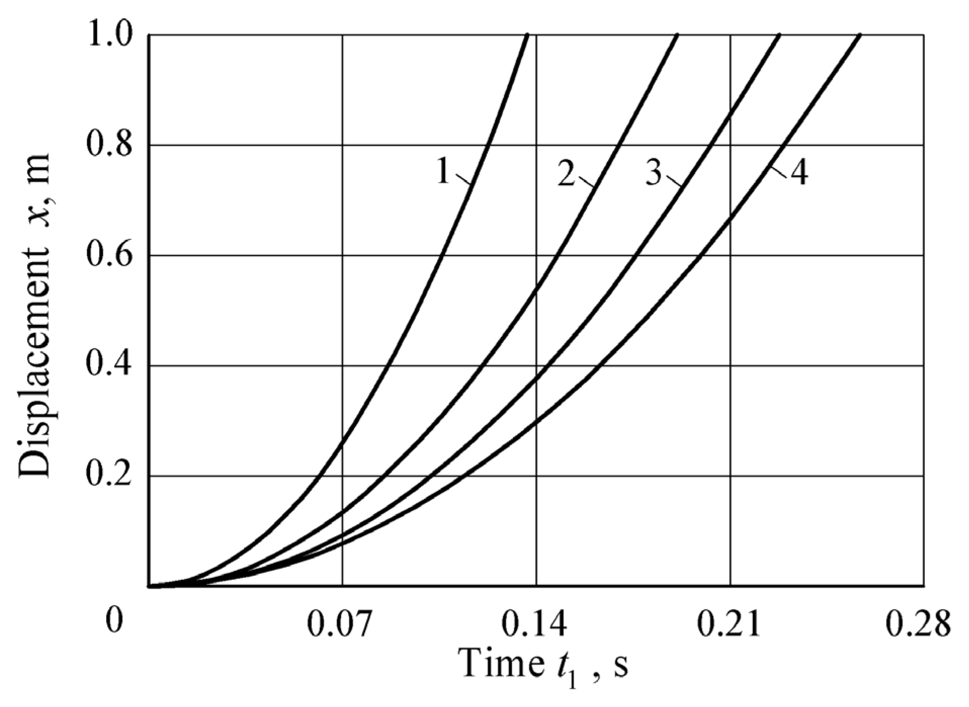
The solution using numerical methods of the developed mathematical model for the movement of a portion of fertilizer through the inclined tube of the pneumatic fertilizer application device, considering the rotation of the applicator tube, demonstrated its functionality [25,26]. The analysis of this mathematical model showed that the key parameters significantly influencing the fertilizer dose movement time t 1 are the mass m of fertilizer dose and airflow pressure force F p . For a more detailed analysis of how these parameters affect process, graphical dependencies of the fertilizer dose movement x over time t 1 along the inclined applicator tube were constructed (Figure 6 and Figure 7).
The obtained graphical dependencies allow for an accurate determination of the time t 1 it takes for a fertilizer portion of a given mass m to leave the applicator tube and continue its flight to the root zone of the plant. This time t 1 directly depends on the structural and kinematic parameters of the fertilizer application device itself and on the parameters of the accompanying airflow.
All curves in Figure 7 demonstrate accelerated displacement, indicating the influence of the thrust force of the airflow. The greater the mass of the fertilizer dose, the slower it accelerates, which can be explained by inertial properties. For example, an increase in mass ( m = 0.04 kg) leads to a decrease in the displacement rate.
We can also say that the exit time directly depends on the design of the device and the characteristics of the airflow. Thus, reducing the mass of the fertilizer dose contributes to faster movement and reaching the final point. The structural parameters of the device and the airflow characteristics have a significant impact on the fertilizer displacement speed. These dependencies are important to consider when designing the fertilizer delivery system to ensure precise application to the plant’s root zone.
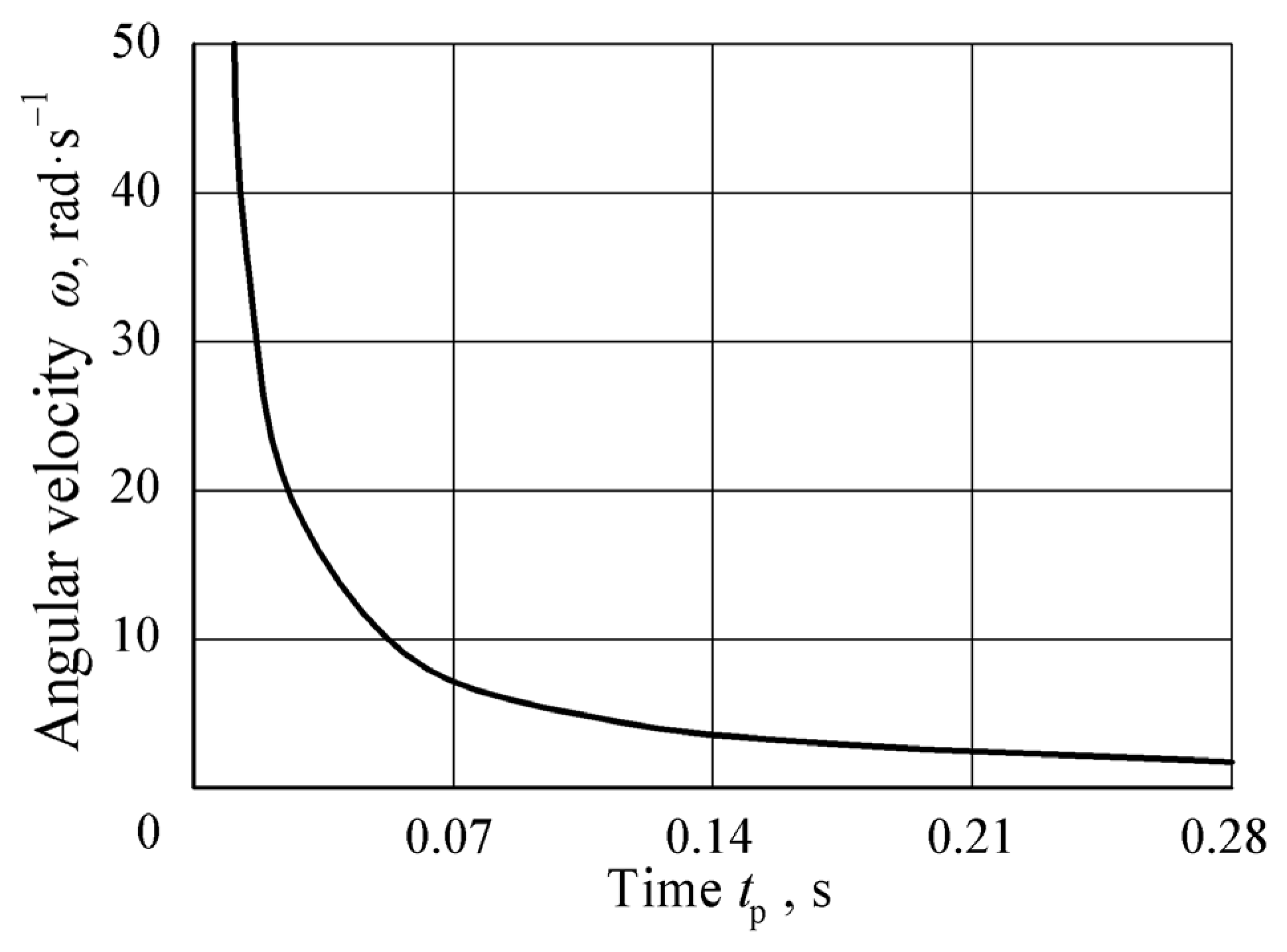
Figure 8 and Figure 9 present the results of the practical application of the developed mathematical model of fertilizer dose movement in the proposed pneumatic device for precision fertilizer application. These figures show the calculated results of the required angular velocity of the applicator tube rotation mechanism as a function of time needed to rotate it to the maximum set angle of β = 30 deg.
The dependence in Figure 8 illustrates the time required for a fertilizer particle to pass through the channel of the applicator tube with a length of L = 0.6 m and the necessary airflow pressure force during this process. Thus, the obtained dependencies allow for full synchronization of the fertilizer particle movement time with the time required for the farming robot to travel the distance between adjacent plants in a row.
Additionally, the results of mathematical modeling allow for more precise synchronization of the ejection time t 1 of the fertilizer portion from the inclined applicator tube and the time t p of its rotation.
Comparison of the theoretical and experimental data demonstrated a high level of agreement in both cases. A graphical comparison of the results is presented in Figure 10.
For the 10 g dose, the mean absolute error was 0.030 s, the relative error was about 3%, the correlation coefficient was 0.995, and the coefficient of determination was R2 = 0.989, confirming the high accuracy of the model. For the 40 g dose, the mean absolute error was 0.009 s, while the relative error increased to 9.5%. The Root Mean Squared Error (RMSE) value of 0.000811, correlation coefficient of 0.992, and R2 = 0.984 indicate a sufficiently strong agreement between the calculated and experimental results.
The increase in relative error for the larger dose is explained by the greater number of particles, which introduces additional variations in the movement process, while the transit time was recorded up to the moment when the last particle exited the tube, increasing the data spread. The obtained results confirm the adequacy of the model and its suitability for further use, while highlighting the need to detail particle interaction effects in future DEM-based studies.
Previous studies confirm the effectiveness of simulation and experimental validation for improving fertilizer and seeding devices. Lv et al. [27] demonstrated the usefulness of the Discrete Element Method (DEM) for modeling particle motion and optimizing metering systems, reducing prediction errors to below 12%. Similarly, in our work time–displacement dependencies were constructed for different fertilizer doses (0.01–0.04 kg) and airflow pressures (1–3 N), confirming that modeling is essential for improving application accuracy.
The study of Xiong et al. [28] showed that a mechanical–pneumatic seed metering device can achieve high accuracy and versatility when airflow velocity and structural parameters are optimized. In our case, it was established that synchronization between the fertilizer particle ejection time and the applicator tube rotation angle is the key factor for precision during continuous robot motion.
According to Bangura et al. [29], spiral grooved-wheel metering devices outperform straight-groove designs by improving uniformity and discharge rate, with DEM simulations showing good agreement with experiments. This supports our finding that synchronization of particle dynamics with applicator geometry is critical to achieving precise delivery.
Zhong et al. [30] proposed a flow-adsorption principle for quinoa seeding, reducing particle accumulation and improving uniformity compared with traditional suction devices. Their work highlights that both dosing and the timing of particle–device interaction strongly affect performance. Our research adds a new perspective by showing that, for fertilizers, not only the dose but also the synchronization of ejection time with tube orientation relative to the plant ensures accurate placement and minimizes losses.
Valero et al. [31] presented a proof-of-concept robotic platform for single-plant fertilization in organic cropping, integrating Light Detection and Ranging (LiDAR), multispectral imaging, and a robotic arm to deliver site-specific doses of liquid fertilizer. Their results showed that accurate plant detection and platform localization (error below 0.005 m after convergence) enabled precise application around individual plants, thus reducing waste and avoiding crop damage. Although their focus was on organic vegetables and liquid fertilization, the study highlights the same principle demonstrated in our research: fertilization must be plant-oriented rather than field-oriented. Unlike our pneumatic dosing system, which relies on synchronization of fertilizer ejection with robot movement, their approach emphasizes advanced sensing and plant health assessment. Both methods converge on the goal of improving resource efficiency and minimizing environmental impacts.
Cheng et al. [32] analyzed a pneumatic fertilizer discharge system using coupled EDEM–FLUENT simulations and bench tests, demonstrating that stable particle transport can be maintained without blockages when inlet air speeds are within the range of 30–40 m s−1. Their results indicated low coefficients of variation for row-to-row discharge consistency (3.93–5.55%), confirming the suitability of pneumatic systems for multi-row fertilization with high efficiency and uniformity. These findings align with our results, where airflow pressure and synchronization with particle release time proved decisive for application accuracy. Both studies emphasize that maintaining stable airflow parameters minimizes backflow effects and ensures precise dosing, supporting the broader conclusion that pneumatic-assisted delivery can significantly improve the efficiency and reliability of fertilizer application systems
The outcomes of this study align with earlier works where mathematical and numerical models were validated by experimental tests. Similarly to the combination of DEM simulations and bench trials reported by Lv et al. [27], Bangura et al. [29], and Cheng et al. [32], our use of experimental transit-time data for 0.01 kg and 0.04 kg doses confirmed the adequacy of the developed model. The observed dependence of fertilizer transport on airflow force and dose size further supports prior evidence that aerodynamics and system geometry are decisive factors for particle velocity and uniformity [28,29]. Finally, the integration of the dosing mechanism into a robotic platform highlights the importance of synchronization between perception and actuation modules, echoing the plant-oriented fertilization strategies demonstrated by Valero et al. [31]. Together, these findings strengthen the case for coupling validated modeling approaches with system-level engineering solutions to achieve higher precision and sustainability in robotic fertilization.
In summary, our results are consistent with earlier works yet extend them by demonstrating the importance of coupling temporal and spatial parameters of fertilizer delivery. The developed technical solution and mathematical model are highly versatile and can be adapted to various operating conditions, including work on uneven terrain and in confined spaces, such as orchards or berry plantations. Accordingly, the use of the modular fertilizer application device opens up prospects for further development of precision farming technologies.

4. Limitations and Future Work

This study primarily focused on developing and experimentally verifying a simplified model of fertilizer particle motion, using transit time measurements of 0.01 kg and 0.04 kg doses through a 0.019 m × 1 m tube as a benchmark. While the results confirm the adequacy of the proposed approach, certain aspects remain outside the current scope. In particular, possible particle breakage due to collisions with the pipe wall, the limits of airflow capacity at higher dosing rates, and the coupled dynamics of multiphase transport will require further investigation. Although the accumulation chamber of the device is already equipped with a check valve that prevents backflow, future research will incorporate DEM-based simulations to analyze particle–wall interactions and air–particle coupling, providing a more comprehensive description of the process and supporting optimization for different operating conditions.
Future developments will focus on the transition from theoretical research to integrated system-level validation of the proposed robotic fertilizer applicator. At present, prototypes of the agro-robot, the mobile support station, and the battery replacement unit have already been manufactured and are under experimental investigation, while the artificial vision subsystem remains at the stage of theoretical study. To meet the technological demand for compressed air, the agro-robot is equipped with a 10 L receiver and an Air-Zenith 2nd Gen. 200PSI AZOB2 air compressor (Air-Zenith, Las Vegas, NV, USA). Complete pressurization of the receiver is performed during battery replacement, which lasts about two minutes, with the compressor powered by the electrical grid of the mobile support station; during field operation, the compressor only maintains the required pressure level. Future work will also address the synchronization of the applicator, the artificial vision system, and the translational movement of the agro-robot to ensure reliable and precise fertilizer placement. The outcomes of these ongoing experimental investigations will be reported in subsequent publications.

5. Conclusions

  • As a result of the conducted research, a new design solution for a device for precise mineral fertilizer application to the root zone of plants using a farming robot has been proposed. This contributes to the implementation of precision farming technology and enables the efficient and accurate application of fertilizers to specific points in the field.
  • It was established that the synchronization of the fertilizer particle ejection time t 1 from the applicator tube and the angle β of its rotation towards the plant is a key factor in ensuring the accuracy of fertilizer application during the continuous movement of the farming robot. To improve the accuracy of this process, graphical dependencies of the fertilizer dose movement x over time t 1 were constructed and analyzed for different masses ( m = 0.01–0.04 kg) and airflow pressure forces ( F p = 1–3 N).
  • Experimental comparison confirmed the adequacy of the developed model for predicting the transit time of fertilizer portions through the tube. For a mass of 0.01 kg, the relative error was approximately 3%, and for 0.04 kg, about 9.5%, which is explained by the increased number of particles and the fixation of the exit moment of the last granule. The obtained results confirm the reliability of the model and provide a basis for its further refinement using DEM modeling. Future DEM simulations will evaluate particle–wall collisions, granule breakage, and airflow interactions to further optimize application precision and efficiency.
  • The conducted research creates prerequisites for minimizing energy costs through the efficient use of compressed air, as well as for reducing fertilizer losses and improving their effectiveness.
  • The research results have practical significance for agricultural engineering, as the proposed design contributes to the integration of robotic systems into the agricultural sector.

Author Contributions

Conceptualization, J.O. and Y.I.; methodology, J.O. and T.L.; software, O.L.; validation, T.L., O.L. and J.O.; formal analysis, O.L.; investigation, T.L. and Y.I.; writing—original draft preparation, Y.I.; writing—review and editing, T.L. and O.L.; visualization, Y.I., O.L. and T.L.; supervision, J.O.; project administration, J.O.; funding acquisition, J.O. All authors have read and agreed to the published version of the manuscript.

Funding

This publication was supported by development fund project PM210001TIBT “Development of precision fertilization technology for cultivated berries” from the Estonian University of Life Sciences.

Data Availability Statement

The original contributions presented in this study are included in the article. Further inquiries can be directed to the corresponding author(s).

Conflicts of Interest

The authors declare that they have no known competing financial interests or personal relationships that could have appeared to influence the work reported in this paper.

References

  1. Hofstee, J.W.; Huisman, W. Handling and spreading of fertilizers part 1: Physical properties of fertilizer in relation to particle motion. J. Agric. Eng. Res. 1990, 47, 213–234. [Google Scholar] [CrossRef]
  2. Cerović, V.; Petrovic, D.; Radojevic, R.; Barac, S.; Vukovic, A. On the fertilizer particle motion along the vane of a centrifugal spreader disc assuming pure sliding of the particle. J. Agric. Sci. 2018, 63, 83–97. [Google Scholar] [CrossRef]
  3. Cointault, F.; Sarrazin, P.; Paindavoine, M. Measurement of the Motion of Fertilizer Particles Leaving a Centrifugal Spreader Using a Fast Imaging System. Precis. Agric. 2003, 4, 279–295. [Google Scholar] [CrossRef]
  4. Cool, S.; Pieters, J.; Mertens, C.K.; Hijazi, B.; Vangeyte, J. A simulation of the influence of spinning on the ballistic flight of spherical fertilizer grains. Comput. Electron. Agric. 2014, 105, 121–131. [Google Scholar]
  5. Cool, R.S.; Pieters, G.J.; Acker, V.J.; Van Den Bulcke, J.; Mertens, C.K.; Nuyttens, R.E.D.; Van De Gucht, C.T.; Vangeyte, J. Determining the effect of wind on the ballistic flight of fertilizer particles. Biosyst. Eng. 2016, 151, 425–434. [Google Scholar]
  6. Adamchuk, V.; Bulgakov, V.; Beloev, H.; Korenko, M. Mineral Fertilization Theory and Working Tools of Fertilizer Spreading Machines; Professor Marin Drinov Publishing House of Bulgarian Academy of Sciences: Sofia, Bulgaria, 2017; p. 165. [Google Scholar]
  7. Aphale, A.; Bolander, N.; Park, J.; Shaw, L.; Svec, J.; Wassgren, C. Granular fertiliser particle dynamics on and off a spinner spreader. Biosyst. Eng. 2003, 85, 319–329. [Google Scholar] [CrossRef]
  8. Villette, S.; Cointault, F.; Piron, E.; Chopinet, B.; Paindavoine, M. Simple imaging system to measure velocity and improve the quality of fertilizer spreading in agriculture. J. Electron. Imaging 2008, 17, 31–109. [Google Scholar] [CrossRef]
  9. Adamchuk, V.; Ratushnyi, V. Pneumatic Seeder for Subsoil Application of Mineral Fertilizers. Patent of Ukraine UA117844, 10 October 2018. (In Ukrainian). [Google Scholar]
  10. Lillerand, T.; Virro, I.; Maksarov, V.; Olt, J. Granulometric Parameters of Solid Blueberry Fertilizers and Their Suitability for Precision Fertilization. Agronomy 2021, 11, 1576. [Google Scholar] [CrossRef]
  11. Virro, I.; Arak, M.; Maksarov, V.; Olt, J. Precision fertilisation technologies for berry plantation. Agron. Res. 2020, 18, 2797–2810. [Google Scholar]
  12. Dawson, C.J.; Hilton, J. Fertilizer availability in a resource-limited world: Production and recycling of nitrogen and phosphorus. Food Policy 2011, 36, 14–22. [Google Scholar]
  13. Adamchuk, V.; Vozjik, Y. Method of Pneumatic Transportation for Application of Granular Mineral Fertilizers. Patent of Ukraine UA146033, 20 January 2021. (In Ukrainian). [Google Scholar]
  14. Hatem, A.E.M. Simulation of Rotary Spreader. Ph.D. Thesis, Agricultural Engineering Department, Mansoura University, Mansoura, Egypt, 2013. [Google Scholar]
  15. Bulgakov, V.; Adamchuk, V.; Arak, M.; Petrychenko, I.; Olt, J. Theoretical research into the motion of combined fertilizing and sowing tractor-implement unit. Agron. Res. 2020, 5, 1498–1516. [Google Scholar]
  16. Bulgakov, V.; Adamchuk, V.; Kuvachov, V.; Shymko, L.; Olt, J. A theoretical and experimental study of combined agricultural gantry unit with a mineral fertilizer spreader. Agraarteadus J. Agric. Sci. 2020, 31, 139–146. [Google Scholar]
  17. Bulgakov, V.; Adamchuk, O.; Pascuzzi, S.; Santoro, F.; Olt, J. Research into engineering and operating parameters of mineral fertilizer application machine with new fertilizer spreading tools. Agron. Res. 2021, 19, 676–686. [Google Scholar]
  18. Tijskens, E.; Van Liederkerke, P.; Ramon, H. Modelling to aid assessment of fertiliser handling and spreading characteristics. In Proceedings of the International Fertiliser Society, London, UK, 14 April 2005. No. 553. [Google Scholar]
  19. Krklješ, D.; Kitić, G.; Panić, M.; Petes, C.; Filipović, V.; Stefanović, D.; Obrenović, N.; Lalić, M.; Marko, O. Agrobot Gari, a multimodal robotic solution for blueberry production automation. Comput. Electron. Agric. 2025, 237 Pt B, 110626. [Google Scholar] [CrossRef]
  20. Zhang, L.; Yuan, W.; Jin, C.; Feng, Y.; Liu, G.; Hu, Y. Research Progress on Key Mechanical Components of the Pneumatic Centralized Fertilizer Discharge System. Appl. Sci. 2024, 14, 3884. [Google Scholar] [CrossRef]
  21. Wang, L.; Gao, J.; Qureshi, W.A. Evolution and Application of Precision Fertilizer: A Review. Agronomy 2025, 15, 1939. [Google Scholar] [CrossRef]
  22. Zaman, A.G.M.; Roy, K.; Olt, J. Normalized Difference Vegetation Index Prediction for Blueberry Plant Health from RGB Images: A Clustering and Deep Learning Approach. AgriEngineering 2024, 6, 4831–4850. [Google Scholar] [CrossRef]
  23. Beer, P.F.; Johnston, E.R., Jr.; Mazurek, F.D.; Cornwell, J.P.; Elliot, E.R. Vectormechanics for Engineers—Statics and Dynamics, 9th ed.; The McGraw-Hill Companies, Inc.: New York, NY, USA, 2010. [Google Scholar]
  24. Hibbeler, C.R. Engineering Mechanics–Dynamics, 12th ed.; Prentice Hall: Upper Saddle River, NJ, USA, 2010. [Google Scholar]
  25. Backhaus, K. Multivariate Analysemethoden, 12th ed.; Springer: Berlin/Heidelberg, Germany, 2008; pp. 1–575. [Google Scholar]
  26. Van Liedekerke, P.; Tijskens, E.; Ramon, H. Discrete element simulations of the influence of fertilizer physical properties on the spread pattern from spinning disc spreaders. Biosyst. Eng. 2009, 102, 392–405. [Google Scholar] [CrossRef]
  27. Lv, H.; Yu, J.; Fu, H. Simulation of the operation of a fertilizer spreader based on an outer groove wheel using a discrete element method. Math. Comput. Model. 2013, 58, 842–851. [Google Scholar] [CrossRef]
  28. Xiong, D.; Wu, M.; Xie, W.; Liu, R.; Luo, H. Design and Experimental Study of the General Mechanical Pneumatic Combined Seed Metering Device. Appl. Sci. 2021, 11, 7223. [Google Scholar] [CrossRef]
  29. Bangura, K.; Gong, H.; Deng, R.; Tao, M.; Chuang, L.; Cai, Y.; Liao, K.; Liu, J.; Qi, L. Simulation analysis of fertilizer discharge process using the Discrete Element Method (DEM). PLoS ONE 2020, 15, e0235872. [Google Scholar] [CrossRef]
  30. Zhong, W.; Zhao, X.; Liu, F.; Bai, H.; Dong, W.; Hu, H.; Kong, X. Design and Experiment of Precision Seed Metering Device for Flow Adsorption of Quinoa Seeds. Agriculture 2024, 14, 434. [Google Scholar] [CrossRef]
  31. Valero, C.; Krus, A.; Cruz Ulloa, C.; Barrientos, A.; Ramírez-Montoro, J.J.; del Cerro, J.; Guillén, P. Single Plant Fertilization Using a Robotic Platform in an Organic Cropping Environment. Agronomy 2022, 12, 1339. [Google Scholar] [CrossRef]
  32. Cheng, B.; He, R.; Xu, Y.; Zhang, X. Simulation Analysis and Test of Pneumatic Distribution Fertilizer Discharge System. Agronomy 2022, 12, 2282. [Google Scholar] [CrossRef]
Figure 1. General view of the farming robot during the fertilizer application process: 1—farming robot; 2—fertilizer application device; 3—crop row.
Agriengineering 07 00320 g001
Figure 2. Fertilizer Application Device: 1—hopper; 2—metering unit; 3—accumulation chamber; 4—fertilizer particle; 5—compressed air source; 6—solenoid valve; 7—valve; 8—spring; 9—restrictive surface; 10—applicator tube; 11—treated plant; 12—soil surface; b—distance between plants; h—height at which the end of the applicator tube is placed; c—distance projection from plant to the end of applicator tube onto a horizontal plane.
Agriengineering 07 00320 g002
Figure 3. Fertilizer Application Device (Top View): c 0 and c max —maximum and minimum values of the distance c.
Agriengineering 07 00320 g003
Figure 4. Prototype of the mineral fertilizer applicator: (a) general view; (b) 3D model; 1—metering unit; 2—accumulation chamber; 3—applicator tube; 4—solenoid valve; 5—compressor; 6—air receiver.
Agriengineering 07 00320 g004
Figure 5. Equivalent diagram of the interaction of the fertilizer portion with the surface of the tube, inside which it moves.
Agriengineering 07 00320 g005
Figure 6. Dependence of the fertilizer dose movement x on time t 1 along the applicator tube at different airflow pressure forces F p : (1) F p = 3 N; (2) F p = 2 N; (3) F p = 1 N.
Agriengineering 07 00320 g006
Figure 7. Dependence of the fertilizer dose movement x on time t 1 along the applicator tube at different fertilizer dose masses m : (1) m = 0.01 kg; (2) m = 0.02 kg; (3) m = 0.03 kg; (4) m = 0.04 kg.
Agriengineering 07 00320 g007
Figure 8. Dependence of the angular velocity ω of the applicator tube rotation on time t p at: F p = 1 N; m = 0.01 kg; β = 30 deg; L = 0.6 m.
Agriengineering 07 00320 g008
Figure 9. Dependence of the airflow pressure force F p on time t 1 at: m = 0.01 kg; β = 30 deg; L = 0.6 m.
Agriengineering 07 00320 g009
Figure 10. Dependence of the fertilizer dose movement x on time t 1 along the applicator tube at different fertilizer masses m : 1 and 2—theoretical; 3 and 4—experimental.
Agriengineering 07 00320 g010
Disclaimer/Publisher’s Note: The statements, opinions and data contained in all publications are solely those of the individual author(s) and contributor(s) and not of MDPI and/or the editor(s). MDPI and/or the editor(s) disclaim responsibility for any injury to people or property resulting from any ideas, methods, instructions or products referred to in the content.