Abstract
Modern agriculture, with the use of artificial lighting, requires high-intensity LED luminaires with compact dimensions. In this regard, new approaches to the design of LED luminaires using both new materials and technical solutions have been considered. The theoretical evaluation of the influence of different materials on the efficiency of removal of thermal energy from LEDs was shown. A new material PMS-5 is proposed and evaluated as an immersion liquid, which can be used as an effective heat sink in the lower part of the luminaire up to the level of LEDs located in the top light LED luminaires. The proposed polymethylsiloxane PMS-5 liquid has more than twice the thermal conductivity (0.167 W/(m·K)) of HFE7200 and NS15 liquids used in immersion-cooled LED luminaires. Based on the theoretical evaluation, the requirements for parameters, such as metal profile area, immersion liquid volume, wall thickness area, and external area of the cylinder, are highlighted and shown. The noted parameters have a key role in the design of an efficient top light LED luminaire. It has been shown that the design of the metal profile significantly affects the efficiency of the removal of thermal energy from LEDs and it is necessary to use specialized profiles optimized for the diameter of the LED luminaire cylinder. A number of LED luminaire designs were proposed, depending on the thermal properties of the construction materials, technical and economic performance, as well as actual operating and installation conditions. The analysis of the presented theoretical evaluations allowed overlay of the design basis of LED luminaires within the presented concept and top light.
1. Introduction
The development of light-emitting diodes (LEDs) has made it possible to create compact luminaires with high intensity [1,2]. The use of phosphor coatings has solved the problem of narrow spectral composition of LEDs and significantly expanded their range of application, including as sources of illumination (LED luminaires) when plants are growing in greenhouses and city farms [3,4,5,6]. The main advantages of LED-based luminaires compared to discharge lamps, are long service life, high energy efficiency and light output, and the ability to change the intensity and spectral composition (in the presence of several spectral channels) in a large range [7,8,9,10,11].
LED-based luminaires usually have high irradiation intensity to create a sufficient level of irradiation to ensure efficient plant growth during the absence of natural light. However, such LED luminaires have high thermal energy emissions [12]. Operation of LEDs at high operating temperatures can lead to a decrease in their luminous efficacy, which adversely affects reliability and durability [13,14,15,16,17,18]. Therefore, the development of a design providing effective cooling of LED luminaires is an urgent task. Many studies are aimed at improving heat dissipation from LED sources [19,20,21,22], but most studies are aimed at the development of cooling systems for rounded spot LED lamps [23,24,25], which are rarely used for industrial cultivation in greenhouses. The main methods to intensify thermal energy sinks are the design of fins with perforations, the use of heat pipes, active cooling, and increasing the dissipation area, including at the expense of overall dimensions [19].
The overall dimensions of LED luminaires are important for greenhouse farms because mixed lighting is used in greenhouses (the main lighting is natural; additional illumination of plants is carried out by artificial lighting). Small sizes of luminaires allow minimizing the shading of plants during the light day. For inter-lighting system luminaires, the temperature of the case is also important because, at high temperatures, burns may appear in places of contact with the leaves of plants [26,27]. In most existing industrial LED luminaires with high irradiation intensity, for more efficient heat dissipation, massive aluminum radiators with cooling ribs are used [28], which leads to a significant increase in the cost of luminaire design and increase in the area of shading of natural light.
In a number of scientific articles [29,30,31,32,33], studies were conducted to evaluate the effectiveness of LED cooling by the immersion method. These studies showed that this type of cooling increases the amount of heat dissipated by reducing the thermal resistance of the cooling system elements. There were also proposed designs, using methods of immersion cooling of LEDs in the form of injection of liquid (3M Fluorinert FC-43—liquid for immersion cooling) inside the lamp package [34], which improved heat and light output. Modeling of thermal processes in conventional LED luminaires and immersion-cooled LED luminaires [35] showed that “the junction temperature of liquid cooling lamp is 40 °C lower and the theoretical life time is 6.28 times longer than the traditional LED lamp at 3 Watt”. Therefore, there is a relevance to developing LED luminaires adapted for use in greenhouse farms with compact dimensions and high intensity of irradiation.
We have developed and proposed a luminaire design in which the intensification of the heat sink occurs due to immersion cooling [36,37]. The development of an effective design of an LED luminaire with immersion cooling requires the analysis of its thermal and optical characteristics, which implies theoretical and experimental studies. But, it is also worth noting that the optimal design of the LED luminaire will depend on the specifics of its application. At the first stage, two main applications can be distinguished, as a top light and inter-lighting system. At the same time, the requirements for luminaires differ significantly. High irradiation intensity and minimum case dimensions are required from top light luminaires while low case temperature (below 40 °C) and effective light distribution are required from inter-lighting system luminaires to install it among plants. The first variant of application (top light) covers a significantly larger scale of implementation of LED luminaires, so its design will be analyzed first.
In this article, the design features of the LED top-light luminaire will be considered in order to optimize its design, which will identify the most important aspects in the design of LED luminaires of the top row. The basis obtained in this study will allow understanding the directions that require further, more detailed research.
2. Materials and Methods
This study proposes a linear design of LED luminaire. The linear LED luminaire is a transparent cylinder, inside of which a metal profile with LEDs placed on it is located along its entire length, while the whole internal space in the cylinder and in the metal box is filled with a transparent thermally conductive dielectric liquid (Figure 1).
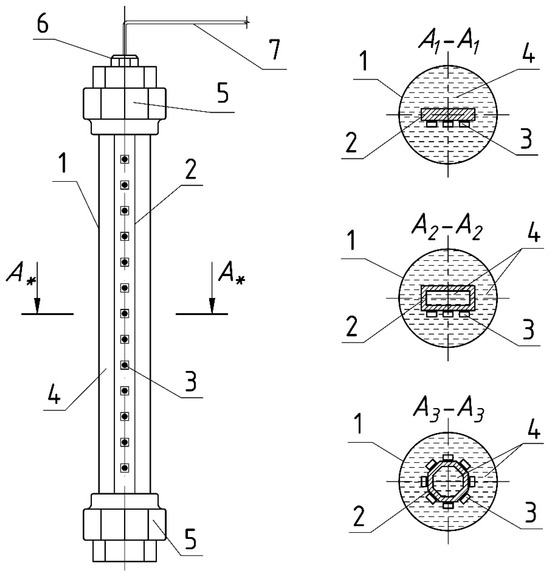
Figure 1.
The developed LED luminaire [36]. 1—transparent cylinder; 2—metal profile; 3—LEDs; 4—transparent dielectric liquid; 5—sealing caps; 6—cable gland; 7—electric cable; *—the asterisk indicates the subscript corresponding to the numbers 1, 2 and 3.
On both sides, the LED luminaire cylinder is closed with sealed end caps. The LEDs are powered via a cable through one of the covers with a sealed cable gland. The power supply unit is placed separately to reduce the dimensions, avoid excessive heating of the luminaire, and increase maintainability. Among the advantages of this design, it is worth noting an effective heat sink from the LEDs themselves and from the metal profile due to the higher thermal conductivity of the liquid used, unlike air. At the same time, effective removal is provided from the front side of the LED, that significantly increases the heat sink in comparison with typical designs of LED luminaires using metal radiators. Structurally, the luminaire consists of a transparent tube made of polycarbonate or glass, inside which is placed an aluminum profile, on which the boards with LEDs are fixed; in the cross-section, the profile can be of different shapes, rectangular or circular cross-section (Figure 1). Obviously, the development of an effective design of such an LED luminaire requires optimization of the shape of this profile and other structural elements of the LED luminaire.
Before conducting full-scale thermal and theoretical studies, it is necessary to analyze the potential capabilities of the LED luminaire, based on the thermal engineering characteristics of the materials (Table 1) used in its structural elements. The following materials are used as materials of construction of the LED luminaire: glass or polycarbonate is used to make a transparent cylinder, an aluminum alloy is used as an area-profile for placing the LEDs, and polymethylsiloxane liquid is used to fill the space inside the cylinder (see Figure 1).

Table 1.
Approximate thermal engineering characteristics of materials used in the design elements of the LED luminaire under development.
The choice between glass and polycarbonate depends on many factors. In terms of heat sink, glass is the most promising material (Table 1). Glass is scratch-resistant, some types pass ultraviolet light, but glass loses to polycarbonate in terms of impact. Due to these features, it is difficult to identify the most suitable material, so the choice between glass and polycarbonate, as a material for a transparent cylinder, requires taking into account the requirements of operating conditions, reliability, efficiency, and must be determined taking into account all these factors.
Analyzing the energy characteristics of the materials of the developed LED luminaire, we will start with the thermal component, which will be determined by the thermal processes that occur during heat removal from the LEDs in the luminaire. In such a process, heat removal occurs by thermal conductivity, convection, and irradiation. We neglected the process of irradiation because, firstly, the liquid a priori should be transparent and, therefore, we can consider that the absorption of photons in the liquid will not be significant, and secondly, the thermal irradiation of other materials of the luminaire will not be significant compared to thermal conductivity and convection.
By eliminating the heat sink by irradiation, the removal of thermal energy from the LEDs through the liquid and the cylinder walls to the external environment will be determined by thermal conductivity and convection. Thermal conductivity primarily determines the heat sink from the LEDs through the metal profile and through the walls of the translucent cylinder (Figure 2). The heat sink through these materials is characterized by their thermal conductivity properties and consequently thermal resistance. In addition to thermal conductivity, there is also the phenomenon of convective energy transfer in the designed LED luminaire. Convection will be observed in the liquid and in the air layers bordering the cylinder (Figure 2).
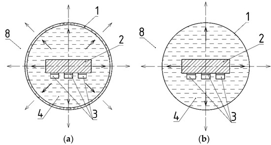
Figure 2.
Thermal energy flows during LED luminaire operation. (a) Scheme of thermal energy flows. (b) Simplified scheme of thermal energy flows. 1—transparent cylinder; 2—metal profile; 3—LEDs; 4—transparent dielectric liquid; 8—environment.
It should be noted that in order to simplify the understanding and representation of processes in the developed LED luminaire, it is assumed that heat is dissipated in four directions (Figure 2b). The first direction represents the energy flow from the front side of the LEDs. In it, the thermal energy is diverted to the environment from the LEDs through the layer of translucent liquid and the part of the cylinder wall in contact with it. The other directions are energy flows from the sides and back of the LEDs. Under these circumstances, the thermal energy is dissipated from the metal profile and then also through the liquid layer and the cylinder wall, to the environment (Figure 2).
The design of the developed LED luminaire, in terms of heat sink from the source to the environment, is a layered pie consisting of several different types of material layers (Figure 2a). In this design, heat from the back of the LEDs is transferred to the metal profile, then to the transparent liquid and then through the polycarbonate cylinder to the environment. All these elements have different thermal resistances and, therefore, different sections of the layered construction of the LED luminaire have different effects on the removal of thermal energy from the LEDs. Figure 3 shows the thermal scheme reflecting the resistance of different elements of the designed LED luminaire.

Figure 3.
Schematic diagram of the thermal energy flow circuit in an LED luminaire. Qt.f—thermal flow from the LEDs to the environment; Rpr.s, Rpr.b—thermal resistance of the side and back of the aluminum profile; Rliq.f, Rliq.s, Rliq.b—thermal resistance of the liquid layer on the front, side, and back of the LEDs, respectively; Rw.f, Rw.s, Rw.b—thermal resistance of the front, side, and back of the transparent cylinder wall.
Note that in order to simplify the thermal circuit, a number of thermal resistances of the elements arising from the heat flow, from the LED crystals through the LED board to the metal profile, were neglected.
As we can see from the basic design and thermal circuit diagram (see Figure 3), the thermal resistance of the profile, the liquid, and the wall of the transparent cylinder have a significant influence on the removal of thermal energy from the LEDs and, accordingly, on the design of the luminaire. Therefore, it is necessary to determine the thermal resistance parameters of these elements.
The thermal characteristics of thermal conductivity in a wall of a complex shape are calculated through Fourier differential thermal conductivity equations [38]. However, for initial estimation of thermal conductivity and resistance in the same unit volume elements of the LED luminaire design, the resistance of the profile and the wall can be found by applying the formulation [39]:
where
- lM—length of the thermal circuit section in the material, m;
- SM—cross-sectional area of the material section, m2;
- λM—thermal conductivity coefficient of the profile material, W·m−1·K−1.
Thermal resistance of the liquid is determined by even more complex calculations of solving systems of differential equations, including one of the most important, the Navier–Stokes equation [40]. Therefore, the calculations of such a complex process of convective heat exchange are accepted to consider the phenomenon of thermal conductivity, using the equivalent thermal conductivity coefficient λliq.eq. Whereupon the thermal resistance of the fluid is calculated according to the formulation:
where
- lliq—length of the section (thickness) of the heat chain in the liquid, m;
- Sliq—cross-sectional area of the fluid section, m2;
- λliq—equivalent thermal conductivity coefficient of liquid, W·m−1·K−1;
The equivalent thermal conductivity coefficient for a fluid in a narrow gap is found by the following formula [41,42]:
where
- Grliq—Grasgof number;
- Prliq—Prandtl number;
- Raliq—Rayleigh number;
- λliq—fluid thermal conductivity coefficient W·m−1·K−1.
The Rayleigh number is calculated using the formulation [39,41]:
where
- g—acceleration of free fall, 9.8 m·s−2;
- βliq—coefficient of volumetric expansion of the liquid, K−1;
- Tled—temperature of the outer part of the LED line, K;
- Tc—temperature of the inner wall of the cylinder, K;
- vliq—coefficient of kinematic viscosity of liquid, m2·s−1;
- aliq—coefficient of thermal diffusivity for liquid, m2·s−1.
In turn, the coefficient of thermal diffusivity is calculated by the formulation [39,41]:
where
- Cliq—heat capacity of liquid, J·kg−1·K−1;
- ρliq—liquid density, kg·m−3.
According to Formulas (3)–(5) and tabular data, the thermal conductivity of the materials used in the construction of the LED luminaire is found. When determining the Rayleigh number, according to Formulation (4), the temperature difference between the outer part of the LED line and the inner wall of the cylinder was taken 50 K as the most probable. At the same time, the temperature difference up to 100 K does not significantly affect the determined parameters.
Since we need to evaluate the potential of each material of the structure in terms of thermal conductivity in the same areas, it is necessary to determine the thermal resistance of these materials for a unit volume according to Formulations (1) and (2). As a unit volume, we take the value equal to 10 mm3 as the most optimal for evaluating the thermal engineering processes in the LED luminaire design.
3. Results and Discussion
Having determined the thermal conductivities and recalculating them in the thermal resistance of materials of LED luminaires construction for a certain volume, we obtain values characterizing the potential possibilities of heat energy dissipation from the LED luminaire. The found values are summarized in Table 2.

Table 2.
Thermal resistances of materials of LED luminaire construction at a volume of 10 mm3.
The values obtained in the table, found for 10 mm3 volume of materials, do not always reflect the valid values for the liquid, because the intensity of the convection process strongly depends on different liquid thickness (Figure 4), and volume (Figure 5). Figure 4 shows the dependence of the thermal resistance on the liquid thickness, with a constant area equal to 10 mm2, found according to Formulation (2).
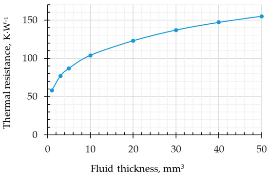
Figure 4.
Dependence of fluid resistance on its thickness at a fixed area of 10 mm2.
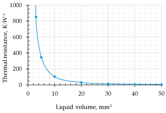
Figure 5.
Dependence of liquid resistance on its volume.
According to the dependence presented in Figure 4, we see that the thermal resistance in the liquid has a nonlinear character and depends significantly on the thickness. At convection, the least resistance of the liquid will be observed at the minimum thickness of the liquid layer. It is also worth noting that at a thickness greater than 10 mm, the growth of thermal resistance is not significant; at a thickness of 50 mm and the above-mentioned liquid parameters, the value is about 155 K·W−1.
If, with an increasing thickness of the liquid, the resistance increases, then the inverse dependence is observed with increasing volume (see Figure 5). At a liquid volume over 10 mm3, the resistance decreases significantly. It is connected with nonlinearity of area growth at growth of liquid thickness (see Formulation (2)). Thus, when optimizing the luminaire by its overall dimensions, it is necessary to take into account the nonlinearity of the change in the presented characteristics.
As we can see from the design of the LED luminaire (Figure 1 and Figure 2), the aluminum profile and polymethylsiloxane liquid are those materials whose configurations can be easily varied to increase the heat sink. Comparing the thermal resistance of these two materials (Table 2 and Figure 4), it becomes obvious that even with a minimum thickness of liquid less than 10 mm, the thermal resistance of polymethylsiloxane liquid is significantly higher than the resistance of the aluminum profile. It follows that the area of the metal profile should be maximized, while it will always be limited by the internal space of the cylinder due to design features. Also, since in our construction the heat must be diverted to the outside air, it is necessary to ensure the most efficient heat path to the air due to high thermal conductivity is through metal, as well as the shortest path through materials with low thermal conductivity and high resistance (Figure 2 and Figure 3). As a consequence, the maximum possible metal path to the cylinder wall and the maximum area are required according to the formulation:
where
- Spr—area of the metal profile on which the LEDs are placed, m2;
- Sin.c—area of the inner wall of the luminaire cylinder, m2.
The studied design, where the LED luminaire is placed on top of the plants, implies that the LEDs are located at the bottom of the luminaire (Figure 2). And, this arrangement creates a space filled with polymethylsiloxane liquid between the LEDs and the cylinder wall. In this space below the LEDs, there is no convection between the upper heated surface (where the LEDs are located) and the bottom of the cylinder [42]. The absence of convection is due to the lack of space for upward fluid flows due to the heating of only the upper vertical area. In this area, heat will be transferred only due to the thermal conductivity of the liquid, which will significantly worsen the thermal conductivity from the bottom of the LED luminaire. Therefore, due to the noted features, it is necessary to reduce the liquid layer between the LEDs and the cylinder by using the circular shape of the LED area (Figure 6), also thereby providing a larger profile area according to Formulation (7).
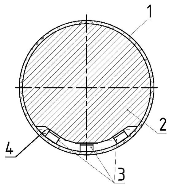
Figure 6.
Design of the LED luminaire. 1—transparent cylinder; 2—metal profile; 3—LEDs; 4—transparent dielectric liquid.
On the basis of the above-mentioned, one more condition is necessary to be observed in order to maximize the heat sink efficiency of the luminaire:
where is the volume of translucent liquid in the developed LED luminaire.
Then, according to the proposed design (Figure 6) and condition (7), it is assumed that the liquid will essentially act as a thermal paste and fill those parts of the luminaire where low thermal resistance is required between the aluminum profile and the cylinder wall, as well as between the LEDs and the cylinder wall. It is clear that the design should provide the necessary space for the LEDs and provide the required angle of light distribution depending on the task at hand.
Due to the fact that the thermal resistance of polycarbonate and glass does not have high values (Table 2), its walls should have a minimum thickness to provide the least resistance to heat flow. In this regard, the wall thickness is regulated by the following formulation:
where is the thickness of the cylinder wall.
Obviously, the cylinder walls must be resistant to the regulated mechanical impacts.
Since the thermal resistance of air is the highest, it becomes evident that the design of the LED luminaire, for maximum effective cooling, should have a maximized diameter and correspondingly increased cylinder area:
where is the external area of the cylinder.
The area allows for an increased heat sink to the air and, consequently, reduces both the operating temperature of the LEDs and the temperature of the cylinder itself, which is important for certain purposes of the LED luminaire.
The conditions (6)–(9) identified above, which ensure maximum efficiency in ideal conditions, should be adjusted to meet the requirements of real conditions, which are primarily dictated by economic requirements, as well as production requirements and ease of installation.
In this regard, the LED mounting area should most often have a flat surface. From the point of view of saving material for manufacturing the metal profile, it should be replaced by a profile of the same rounded cross-section, but with ribs that will take less heat away from the LEDs, while at the same time significantly reducing its metal consumption (Figure 7b). Alternatively, the profile can be without ribs at all (Figure 7a). Such requirements are dictated by the high price of metal, from which the profile is made, and the low price of polymethylsiloxane liquid, used in the design of the LED luminaire under development. However, to improve the heat sink to the environment, it is necessary that there be as many ribs as possible.
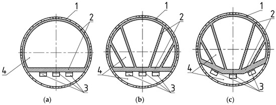
Figure 7.
Proposed LED luminaire designs. (a) profile without ribs; (b) profile with ribs and a flat platform for LEDs; (c) profile with ribs and inclined platform for LEDs. 1—transparent cylinder; 2—metal profile; 3—LEDs; 4—transparent dielectric liquid.
The space between the ribs can be filled with either air or liquid. The use of liquid is most justified because it has better thermal conductivity in comparison with air. In [43], the thermal engineering properties of the liquid, which are the most demanded for immersion cooling, were evaluated. In their study, it was shown that the highest values are possessed by the liquids HFE7200 and NS15. Their thermal conductivity is equal to 0.075 W m−1·K−1, which is significantly lower than the thermal conductivity of PMS-5 liquid equal to 0.167 W m−1·K−1 (Table 3) taken as a basis in this work. The high thermal conductivity indicates the best heat sink of the PMS-5 liquid in conditions where there is no convection. But, when conditions with convective thermal conductivity occur, it is necessary to compare the thermal resistance of the liquid layer under convection. According to the Formulation (2), the thermal resistance of the HFE7200 liquid was calculated for the volume of 10 mm3, which amounted to 95 K·W−1. The thermal resistance of PMS-5 for a volume of 10 mm3 was 104 K·W−1 (Table 3, Figure 4 and Figure 5). From this, it follows that at convection in a small volume, the heat sink will be better when using HFE7200 fluid. At the same time, according to the characteristics, PMS-5 is a more universal liquid, because it has a higher thermal conductivity and will significantly better dissipate LEDs heat from the bottom and at the same time will not be much worse than HFE7200 to dissipate heat by convection from the top.

Table 3.
Thermal characteristics of immersion cooling fluid used in the LED luminaire design.
Designs in which the LEDs will be positioned at a small angle relative to their vertical location will have certain prospects. This can be accomplished by an area with some rounding or places for LEDs, made of several equal areas, with the central area placed in the middle horizontally, and the others on the sides at a slight angle to the horizon, thereby reducing the layer of liquid to the wall of the luminaire cylinder (Figure 7c).
In some cases, due to the lack of specialized profiles, the structure can also be made of rectangular or square profiles (Figure 8). Taking into account the above-mentioned arguments and the given thermal engineering indicators, it is obvious that in such structures the faces of rectangular and square profiles should be as close as possible to the cylinder walls.
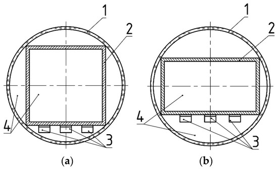
Figure 8.
Proposed LED luminaire designs. (a) Square profile; (b) rectangular profile. 1—transparent cylinder; 2—metal profile; 3—LEDs; 4—transparent dielectric liquid.
The optimization of the LED luminaire under the presented concept of the transparent cylinder design has been discussed above. The analysis of the thermal resistance of the LED luminaire elements shows that the presented concept can be improved; the new concept would require the elimination of a part of the transparent cylinder in the circumference of the LED luminaire. Then, there will be only a segment of the transparent cylinder, which will be located at the bottom of the luminaire in the area where the LEDs are located (see Figure 9).
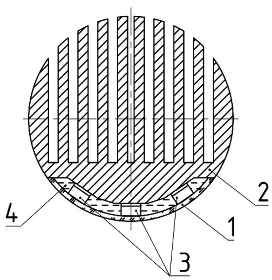
Figure 9.
Design of the LED luminaire. 1—transparent cylinder; 2—metal profile; 3—LEDs; 4—transparent dielectric liquid.
The proposed design will allow removal of the high thermal resistance of polycarbonate (see Table 2), as well as improvement of the heat sink to the surrounding air. At the same time, the metal profile should have ribs to increase the heat sink surface area. The area for the LEDs should have sufficient thickness for efficient and uniform heat dissipation from the LEDs to the ribs. Naturally, this design will need to optimize the thickness and shape of the ribs, the distances between the ribs, and the thickness of the LED area.
In the design of the proposed LED luminaires, the location of the phosphor is also important. If blue light LEDs are used, and the phosphor is located remotely from the LED on the inner wall of the translucent cylinder, it is possible to provide an increase in the optical and thermal properties of the LED luminaire. In [31], the remote location of the phosphor from the LED chip increased the light output by almost 13%, and 12% was due to thermal enhancements. The remote location of the phosphor provides a synergistic effect, as the liquid increases the cooling of the crystal and phosphor [31,44], which leads to an increase in the lifetime of LEDs and improves the luminous efficiency of the phosphor.
In many of the designs presented in this article, the main role of the fluid is to remove heat from the front of the LEDs. But, with a vertical arrangement of LEDs, as already noted, convection will not be observed [42]. However, if the location of LEDs at an angle as in the designs is used (Figure 7c and Figure 9), then in the site of sloping areas for the LEDs, the luminaire will appear convection of the liquid and improve the heat sink. In this regard, the selection of liquid in the lower part of the luminaire before the LEDs should be carried out, taking into account the factor of absence or presence of convection. In the first case, it is necessary to select a liquid with high optical properties and high thermal conductivity, such as PMS-5. In the second case, if convection occurs, it is necessary to select a liquid with high optical properties and take into account the convective properties of the heat sink, such as HFE7200. Thus, the location of LEDs has its own important nuances that directly affect the thermal efficiency and the choice of liquid for immersion cooling.
Studies of different variants of the LED luminaire configuration, based on these design features and a number of studies conducted, will be carried out in future works. It will be necessary to take into account the requirements of production, installation, economics, and design.
Optimization of the cylinder diameter will also require additional research, since, from the point of view of efficiency, the area and volume should be maximized (see condition (4) and Figure 5), but from the economic point of view, it is necessary to reduce the diameter in order to reduce the metal consumption of the profile, the volume of liquid and the material consumption of the cylinder wall. It is observed that the side surface area of the cylinder grows linearly with increasing radius, but the volume of space inside the cylinder increases quadratically. This peculiarity will also bring its own idiosyncrasies in determining the optimal diameter of the cylinder.
It should be noted that this article considers the concept of a linear luminaire with a circular cross-sectional shape; when considering other shapes, the above calculations may not be valid.
4. Conclusions
Implementation of plant cultivation tasks requires a specialized approach to the design of LED luminaires. In this regard, new design concepts for linear LED luminaires have been proposed, providing more compact dimensions and better heat sink from LEDs. Compared to air-cooled luminaires, the presented luminaires have a significant advantage in cooling from the front side of the LED panel, since from the front side, the heat sink is carried out by polymethylsiloxane liquid, which has a significantly higher thermal conductivity compared to air.
In this study, it was shown that the design of the metal profile significantly affects the efficiency of the removal of thermal energy from LEDs, and the use of specialized profiles optimized for the diameter of the LED luminaire cylinder is required. At the same time, there were proposed designs that provide the most effective cooling of the light source (see Figure 6 and Figure 9), as well as designs whose efficiency is somewhat reduced in order to achieve better performance (see Figure 7 and Figure 8).
The proposed designs were analyzed, taking into account the thermal engineering properties of the construction materials, technical and economic indicators, and real conditions of operation and installation. The analysis allowed us to identify the most important aspects in the design of LED luminaires which were presented in Formulations (6)–(9). This made it possible to lay the structural basis of LED luminaires within the presented concepts. It was also shown that the thermal engineering characteristics of the liquid used for immersion cooling are important and the processes occurring in it are only thermal conductivity and convection. The most optimal characteristics are shown by PSM-5 liquid, which has significantly higher thermal conductivity and is not significantly inferior to other liquids in convective heat energy transfer.
The framework established in the presented work allows for further, more local, and detailed optimization on various parameters, taking into account multiple factors and specialized software.
Author Contributions
Conceptualization and methodology, P.V.T.; validation, P.V.T. and A.A.S.; formal analysis, P.V.T.; investigation, S.A.K.; resources, S.A.K. and D.A.B.; writing—original draft preparation, A.A.S. and P.V.T.; writing—review and editing, Y.A.P. and A.S.D.; visualization, D.A.B.; supervision, Y.A.P.; project administration, A.S.D. All authors have read and agreed to the published version of the manuscript.
Funding
The research was carried out at the expense of the state task of the Ministry of Science and Higher Education of the Russian Federation (FGUN-2022-0008).
Data Availability Statement
The raw data supporting the conclusions of this article will be made available by the authors on request.
Conflicts of Interest
The authors declare no conflicts of interest. The funders had no role in the design of the study, in the collection, analyses, or interpretation of the data, in the writing of the manuscript, or in the decision to publish the results.
References
- Sanderson, S.W.; Simons, K.L. Light emitting diodes and the lighting revolution: The emergence of a solid-state lighting industry. Res. Policy 2014, 43, 1730–1746. [Google Scholar] [CrossRef]
- Esteki, M.; Khajehoddin, S.A.; Safaee, A.; Li, Y. LED Systems Applications and LED Driver Topologies: A Review. IEEE Access 2023, 11, 38324–38358. [Google Scholar] [CrossRef]
- Al Murad, M.; Razi, K.; Jeong, B.R.; Samy, P.M.A.; Muneer, S. Light Emitting Diodes (LEDs) as Agricultural Lighting: Impact and Its Potential on Improving Physiology, Flowering, and Secondary Metabolites of Crops. Sustainability 2021, 13, 1985. [Google Scholar] [CrossRef]
- Yudina, L.; Sukhova, E.; Mudrilov, M.; Nerush, V.; Pecherina, A.; Smirnov, A.A.; Dorokhov, A.S.; Chilingaryan, N.O.; Vodeneev, V.; Sukhov, V. Ratio of Intensities of Blue and Red Light at Cultivation Influences Photosynthetic Light Reactions, Respiration, Growth, and Reflectance Indices in Lettuce. Biology 2022, 11, 60. [Google Scholar] [CrossRef]
- Rakutko, S.A.; Rakutko, E.N.; Medvedev, G.V. Development of an Experimental Phytotron and its Application in the Research on the Energy-ecological Efficiency of Indoor Plant Lighting. Agric. Mach. Technol. 2023, 17, 40–48. (In Russia) [Google Scholar] [CrossRef]
- Smirnov, A.A.; Semenova, N.A.; Dorokhov, A.S.; Proshkin, Y.A.; Godyaeva, M.M.; Vodeneev, V.; Sukhov, V.; Panchenko, V.; Chilingaryan, N.O. Influence of Pulsed, Scanning and Constant (16- and 24-h) Modes of LED Irradiation on the Physiological, Biochemical and Morphometric Parameters of Lettuce Plants (Lactuca sativa L.) while Cultivated in Vertical Farms. Agriculture 2022, 12, 1988. [Google Scholar] [CrossRef]
- Kusuma, P.; Pattison, P.M.; Bugbee, B. From physics to fixtures to food: Current and potential LED efficacy. Hortic. Res. 2020, 7, 56. [Google Scholar] [CrossRef]
- Singh, D.; Basu, C.; Meinhardt-Wollweber, M.; Roth, B. LEDs for energy efficient greenhouse lighting. Renew. Sustain. Energy Rev. 2015, 49, 139–147. [Google Scholar] [CrossRef]
- Paradiso, R.; Proietti, S. Light Quality Manipulation to Control Plant Growth and Photomorphogenesis in Greenhouse Horticulture: The State of the Art and the Opportunities of Modern LED Systems. J. Plant Growth Regul. 2022, 41, 742–780. [Google Scholar] [CrossRef]
- Sipos, L.; Boros, I.F.; Csambalik, L.; Székely, G.; Jung, A.; Balázs, L. Horticultural lighting system optimalization: A rev. Sci. Hort. 2020, 273, 109631. [Google Scholar] [CrossRef]
- Wu, B.-S.; Hitti, Y.; MacPherson, S.; Orsat, V.; Lefsrud, M.G. Comparison and perspective of conventional and LED lighting for photobiology and industry applications. Environ. Exp. Bot. 2020, 171, 103953. [Google Scholar] [CrossRef]
- Katzin, D.; van Mourik, S.; Kempkes, F.; van Henten, E.J. GreenLight–An open source model for greenhouses with supplemental lighting: Evaluation of heat requirements under LED and HPS lamps. Biosyst. Eng. 2020, 194, 61–81. [Google Scholar] [CrossRef]
- Chang, M.H.; Das, D.; Varde, P.V.; Pecht, M. Light emitting diodes reliability review. Microelectron. Reliab. 2012, 52, 762–782. [Google Scholar] [CrossRef]
- Luo, X.; Hu, R.; Liu, S.; Wang, K. Heat and fluid flow in high-power LED packaging and applications. Prog. Energy Combust. Sci. 2016, 56, 1–32. [Google Scholar] [CrossRef]
- Chhajed, S.; Xi, Y.; Gessmann, T.; Xi, J.-Q.; Shah, J.M.; Kim, J.K.; Schubert, E.F. Junction temperature in light-emitting diodes assessed by different methods. Light. Diodes Res. Manuf. Appl. 2005, 16, 5739. [Google Scholar] [CrossRef]
- Shailesh, K.R.; Kurian, C.P.; Kini, S.G. Understanding the reliability of LED luminaires. Light. Res. and Technol. 2017, 50, 1179–1197. [Google Scholar] [CrossRef]
- Park, S.H.; Kim, J.H. Lifetime estimation of LED lamp using gamma process model. Microelectron. Reliab. 2016, 57, 71–78. [Google Scholar] [CrossRef]
- Meng, H.; Kong, F.; Li, K. General Analytical Method for Heat Dissipation of N-Layer High-Power LED Systems. IEEE Access 2021, 9, 158917–158925. [Google Scholar] [CrossRef]
- Li, Z.; Tan, J.; Li, J.; Ding, X.; Tang, Y. A review on thermal management of light-emitting diodes: From package-level to system-level. Appl. Therm. Eng. 2024, 257, 124145. [Google Scholar] [CrossRef]
- Adhikari, R.; Beyragh, D.; Pahlevani, M.; Wood, D. A Numerical and Experimental Study of a Novel Heat Sink Design for Natural Convection Cooling of LED Grow Lights. Energies 2020, 13, 4046. [Google Scholar] [CrossRef]
- Şevik, S.; Abuşka, M.; Özdilli, Ö. Thermal performance analysis of a novel linear LED housing with inner and outer fins. Int. Commun. Heat Mass Transf. 2020, 119, 104970. [Google Scholar] [CrossRef]
- Delendik, K.; Kolyago, N.; Voitik, O. Design and investigation of cooling system for high-power LED luminaire. Comput. Math. Appl. 2021, 83, 84–94. [Google Scholar] [CrossRef]
- Zou, Y.; Xia, Y.; Ren, H.; Zhang, C.; Wang, M.; Tang, X.; Ding, S. Heat dissipation design and optimization of high-power LED lamps. Therm. Sci. Eng. Prog. 2023, 37, 101587. [Google Scholar] [CrossRef]
- Pekur, D.V.; Sorokin, V.M.; Nikolaenko, Y.E. Thermal characteristics of a compact LED luminaire with a cooling system based on heat pipes. Therm. Sci. Eng. Prog. 2020, 18, 100549. [Google Scholar] [CrossRef]
- Wang, M.; Tao, H.; Sun, Z.; Zhang, C. The development and performance of the high-power LED radiator. Int. J. Therm. Sci. 2017, 113, 65–72. [Google Scholar] [CrossRef]
- Hao, X.; Little, C.; Khosla, S. Led inter-lighting in year-round greenhouse mini-cucumber production. In Proceedings of the International Symposium on Light in Horticultural Systems, VII International Symposium Acta Hortic (ISHS Acta Horticulturae 956), Wageningen, The Netherlands, 15–18 October 2012; pp. 335–340. [Google Scholar] [CrossRef]
- Tewolde, F.T.; Shiina, K.; Maruo, T.; Takagaki, M.; Kozai, T.; Yamori, W. Supplemental LED inter-lighting compensates for a shortage of light for plant growth and yield under the lack of sunshine. PLoS ONE 2018, 13, e0206592. [Google Scholar] [CrossRef]
- Paucek, I.; Appolloni, E.; Pennisi, G.; Quaini, S.; Gianquinto, G.; Orsini, F. LED Lighting Systems for Horticulture: Business Growth and Global Distribution. Sustainability 2020, 12, 7516. [Google Scholar] [CrossRef]
- Arik, M.; Utturkar, Y.; Weaver, S. Immersion Cooling of Light Emitting Diodes. In Proceedings of the Intersociety Conference on Thermal and Thermomechanical Phenomena in Electronic Systems, 12th IEEE Intersociety Conference (ITherm 2010), Las Vegas, NV, USA, 2–5 June 2010; pp. 1–8. [Google Scholar] [CrossRef]
- Cengiz, C.; Mete Muslu, A.; Arik, M.; Dogruoz, B. Enhanced Thermal Performance of High Flux LED Systems with Two-Phase Immersion Cooling. In Proceedings of the Intersociety Conference on Thermal and Thermomechanical Phenomena in Electronic Systems, 19th IEEE Intersociety Conference (ITherm 2020), Orlando, FL, USA, 21–23 July 2020; pp. 196–206. [Google Scholar] [CrossRef]
- Kahvecioglu, H.I.; Tamdogan, E.; Arik, M. Investigation of combined optical and thermal effects on phosphor converted light-emitting diodes with liquid immersion cooling. Opt. Eng. 2018, 57, 055101. [Google Scholar] [CrossRef]
- Azarifar, M.; Cengiz, C.; Arik, M. Thermal and optical performance characterization of bare and phosphor converted LEDs through package level immersion cooling. Int. J. Heat Mass Transf. 2022, 189, 122607. [Google Scholar] [CrossRef]
- Arik, M.; Petroski, J.; Weaver, S. Thermal challenges in the future generation solid state lighting applications: Light emitting diodes. In Proceedings of the Intersociety Conference on Thermal and Thermomechanical Phenomena in Electronic Systems (Cat. No.02CH37258), ITherm 2002, San Diego, CA, USA, 27–30 May 2002; pp. 113–120. [Google Scholar] [CrossRef]
- Roffi, T.M.; Idris, I.; Uchida, K.; Nozaki, S.; Sugiyama, N.; Morisaki, H.; Soelami, F.X.N. Improvement of high-power-white-LED lamp performance by liquid injection. In Proceedings of the International Conference on Electrical Engineering and Informatics, 2011 Intl Conf on (PRT), Bandung, Indonesia, 17–19 July 2011; pp. 1–6. [Google Scholar] [CrossRef]
- Zhou, C.; Chen, W.; Liu, X.; Lai, W.; Cheng, X.; Ye, X. The comparative study on thermal performance and life time of liquid cooling LED bulb lamp and traditional LED bulb lamp. In Proceedings of the International Forum on Solid State Lighting, 10th China International Forum (ChinaSSL), Beijing, China, 10–12 November 2013; pp. 122–124. [Google Scholar] [CrossRef]
- Kachan, S.A.; Smirnov, A.A.; Proshkin, Y.A.; Izmailov, A.Y.; Dorokhov, A.S.; Burynin, D.A. Liquid Phyto-Irradiator for Plants. Patent RU 209726 U1, 21 March 2022. [Google Scholar]
- Kachan, S.A.; Smirnov, A.A.; Proshkin, Y.A.; Izmailov, A.Y.; Dorokhov, A.S.; Burynin, D.A. LED Liquid Phyto-Irradiator for Circular Irradiation of Plants. Patent RU 2 777 658 C1, 8 July 2022. [Google Scholar]
- Lykov, A.V. Theory of thermal conductivity. In Textbook Higher School; Higher Education: Moscow, Russia, 1967; p. 600. [Google Scholar]
- Bukhmirov, V.V. Heat and Mass Transfer. In Textbook Ivanovo State Power Engineering University Named after V.I. Lenin; The Science: Ivanovo, Russia, 2014; p. 360. [Google Scholar]
- Campos, D. Handbook on Navier-Stokes Equations: Theory and Applied Analysis; Nova Science Publishers Incorporated: Hauppauge, NY, USA, 2017; p. 506. [Google Scholar]
- Tsvetkov, F.F.; Grigoriev, B.A. Heat and Mass Transfer: A Textbook for Universities, 2nd ed.; Corrected and Enlarged; MPEI Publishing House: Moscow, Russia, 2005; p. 550. [Google Scholar]
- Mikheev, M.A.; Mikheeva, I.M. A Short Course in Heat Transfer; Gosenergoizdat: Moscow, Russia, 1961; p. 208. [Google Scholar]
- Tamdogan, E.; Arik, M. Natural Convection Immersion Cooling With Enhanced Optical Performance of Light-Emitting Diode Systems. J. Electron. Packag. 2015, 137, 041006. [Google Scholar] [CrossRef]
- Arik, M.; Weaver, S.; Becker, C.; Hsing, M.; Srivastava, A. Effects of Localized Heat Generations Due to the Color Conversion in Phosphor Particles and Layers of High Brightness Light Emitting Diodes. In Proceedings of the International Electronic Packaging Technical Conference and Exhibition, ASME 2003, Maui, HI, USA, 6–11 July 2003; pp. 611–619. [Google Scholar] [CrossRef]
Disclaimer/Publisher’s Note: The statements, opinions and data contained in all publications are solely those of the individual author(s) and contributor(s) and not of MDPI and/or the editor(s). MDPI and/or the editor(s) disclaim responsibility for any injury to people or property resulting from any ideas, methods, instructions or products referred to in the content. |
© 2024 by the authors. Licensee MDPI, Basel, Switzerland. This article is an open access article distributed under the terms and conditions of the Creative Commons Attribution (CC BY) license (https://creativecommons.org/licenses/by/4.0/).