Article

Integrating Actuator Fault-Tolerant Control and Deep-Learning-Based NDVI Estimation for Precision Agriculture with a Hexacopter UAV

by
Gerardo Ortiz-Torres
1,
Manuel A. Zurita-Gil
1,
Jesse Y. Rumbo-Morales
1,*,
Felipe D. J. Sorcia-Vázquez
1,
José J. Gascon Avalos
1,
Alan F. Pérez-Vidal
1,
Moises B. Ramos-Martinez
1,
Eric Martínez Pascual
2 and
Mario A. Juárez
3
1
Computer Science and Engineering Department, University of Guadalajara, Ameca 46600, Mexico
2
Natural and Exact Sciences Department, University of Guadalajara, Ameca 46600, Mexico
3
TecNM/ITS Irapuato, Irapuato 36821, Mexico
*
Author to whom correspondence should be addressed.
AgriEngineering 2024, 6(3), 2768-2794; https://doi.org/10.3390/agriengineering6030161
Submission received: 5 June 2024 / Revised: 17 July 2024 / Accepted: 29 July 2024 / Published: 8 August 2024
(This article belongs to the Special Issue Sensors and Actuators for Crops and Livestock Farming)

Abstract

:
This paper presents an actuator fault-tolerant control (FTC) strategy for a hexacopter unmanned aerial vehicle (UAV) designed specifically for precision agriculture applications. The proposed approach integrates advanced sensing techniques, including the estimation of Near-Infrared (NIR) reflectance from RGB imagery using the Pix2Pix deep learning network based on conditional Generative Adversarial Networks (cGANs), to enable the calculation of the Normalized Difference Vegetation Index (NDVI) for health assessment. Additionally, trajectory flight planning is developed to ensure the efficient coverage of the targeted agricultural area while considering the vehicle’s dynamics and fault-tolerant capabilities, even in the case of total actuator failures. The effectiveness of the proposed system is validated through simulations and real-world experiments, demonstrating its potential for reliable and accurate data collection in precision agriculture. An NDVI test was conducted on a sugarcane crop using the estimated NIR to assess the crop’s condition during its tillering stage. Therefore, the main contributions this paper include (i) the development of an actuator FTC strategy for a hexacopter UAV in precision agriculture applications, integrating advanced sensing techniques such as NIR reflectance estimation using deep learning network; (ii) the design of a flight trajectory planning method ensuring the efficient coverage of the targeted agricultural area, considering the vehicle’s dynamics and fault-tolerant capabilities; (iii) the validation of the proposed system through simulations and real-world experiments; and (iv) the successful integration of FTC scheme, advanced sensing, and flight trajectory planning for reliable and accurate data collection in precision agriculture.

1. Introduction

Unmanned aerial vehicles (UAVs) have received substantial attention lately because of their diverse capabilities and potential applications in various fields, including aerial photography, surveillance, oil spill detection, and precision agriculture, among others [1]. Hexacopter UAVs, in particular, have emerged as a popular choice for their stability, payload capacity, and maneuverability [2]. However, the reliability and safety of these vehicles are critical concerns, especially in precision agriculture applications, where accurate data collection and autonomous operation are essential [3]. With the growing applications and extensive integration of automation technology, hexacopter UAVs are becoming more vulnerable to faults. These faults can significantly affect vehicle dynamics, compromising stability, reliability, and safety throughout the flight envelope. Implementing fault-tolerant control strategies and advanced sensing techniques has become increasingly vital for overcoming these challenges, especially in managing actuator failures in hexacopter UAVs [4]. Fault-tolerant control (FTC) methods can be employed to identify malfunctions in real-time and enhance the reliability and safety of UAVs. These FTC techniques are classified into two types: passive and active [5]. Active techniques involve adapting or reconfiguring controller parameters based on Fault Diagnosis (FD) system data, ensuring the system remains stable and performs acceptably.
Fault-tolerant control aims to maintain the stability and performance of a system in the presence of faults. In the context of multicopter UAVs, several studies have investigated FTC approaches to ensure vehicle reliability. For instance, Reference [6] proposed two FTC designs for a hexacopter subject to actuator Loss of Effectiveness (LoE) based on gain-scheduling control. The results of the experiment performed on the UAV show the robustness of the methods. Similarly, Reference [7] developed an active FTC by redistributing the control signals among the healthy actuators with a reconfigurable multiplexing and pseudo-inverse control allocation applied experimentally on a coaxial octocopter UAV. Reference [8] presented a fault-tolerant control framework for a quadcopter in the case of a partial motor fault based on a three-loop nonlinear controller along with a Fault Detection and Isolation (FDI) algorithm. The simulation results demonstrate that the proposed controller has satisfactory performance with actuator damages up to 50%.
Recent advancements in FD techniques have further enhanced the capabilities of fault-tolerant control systems for multicopter UAVs. Reference [9] proposed a novel fault diagnosis method for multicopters based on a machine-learning-based probabilistic framework, utilizing in-flight, out-of-plane strain measurements at each vehicle boom to detect, identify, and quantify rotor faults. Reference [10] developed a robust actuator fault diagnosis algorithm for hexacopter UAVs based on an adaptive exogenous Kalman filter (AXKF) tested in simulation. The results show that the proposed scheme can accurately estimate the actuator fault’s magnitude. These advancements in FD techniques have paved the way for more effective and reliable fault-tolerant control strategies.
Total actuator failures in hexacopter UAVs pose a significant challenge to the vehicle’s stability and controllability. In such scenarios, the UAV loses one or more of its six rotors, leading to a severe degradation in performance and an increased risk of catastrophic failure [11]. To address this issue, researchers have developed specialized fault-tolerant control strategies that can accommodate total actuator failures. For example, Reference [12] proposed a novel FTC scheme that switches from a nominal controller to a fault-tolerant controller, based on a sliding mode controller with control allocation, for a hexacopter UAV. The effectiveness and robustness of the FTC controller are demonstrated in simulation considering an actuator failure. Similarly, Reference [13] developed a fault-tolerant strategy by converting the hexacopter structure into reconfigurable ones by adding a minimum number of servomotors to deal with failures and significantly improve maneuverability under these conditions. An experimental demonstration is shown for the proposed strategy, which will perform well in the case of complete rotor failure. Recently, Reference [14] presented a learning-based tracking controller based on the Gaussian processes for an FTC to perform a recovery maneuver in a hexacopter. The controller is designed to learn and compensate for the modeling uncertainties after a failure with a control allocation reconfiguration. Experimental tests were carried out to evaluate the proposed algorithm. It was observed that the algorithm allows an improvement in the performance of the UAV system.
Precision agriculture relies on accurate data collection and analysis to optimize crop management practices. UAVs equipped with specialized sensors, such as multispectral cameras, have proven to be valuable tools for gathering high-resolution data on crop health and vigor [15]. The Normalized Difference Vegetation Index (NDVI) is a widely used metric for assessing vegetation health, calculated from the reflectance values in the near-infrared (NIR) and red bands [16]. However, acquiring NIR data typically requires specialized sensors, which can be costly and complex to integrate. To overcome this limitation, recent studies have explored the estimation of NIR values from standard RGB imagery. Reference [17] proposed a method for estimating NIR reflectance from RGB images using a radiometric calibration approach, enabling the calculation of NDVI from consumer-grade cameras. Reference [18] developed a deep learning-based approach for estimating NIR reflectance from RGB imagery, demonstrating its effectiveness in generating accurate NDVI maps for precision agriculture applications.
Trajectory planning is another critical aspect of UAV-based precision agriculture, as it directly impacts the efficiency and coverage of data collection. Several studies have focused on developing optimal trajectory-planning algorithms for agricultural UAVs. Reference [19] proposed a genetic-algorithm-based approach for generating optimal trajectories for UAVs in precision agriculture, considering factors such as energy consumption, coverage, and obstacle avoidance. Similarly, Reference [20] proposed a single framework for efficient visual data acquisition using UAVs that combines perception, environment representation, and route planning. The experimental results show the effectiveness of the proposed route planning method. Recently, Reference [21] provides a literature review of numerous strategies and approaches to addressing path-planning problems for multirotor UAVs in the context of precision agriculture. Also, this paper suggested that a visibility-graph-based method using an A* algorithm to address the path length, time efficiency, and energy efficiency challenges has the best performance for agricultural environments. In this context, Reference [22] proposes a coverage path planning method for a spraying drone that efficiently restricts the flight region of interest, avoiding potential collisions. The algorithm has been tested in simulation, showing that it is effective and covers more areas than other approaches. In addition to trajectory planning, developing advanced control strategies has been a critical focus in precision agriculture applications using multicopter UAVs. Reference [23] proposed a path-tracking controller for a class of agricultural multirotors with variable payload under model uncertainties and exogenous disturbances. A neural-network-based adaptive control is used to offset model uncertainties, while a sliding-mode control approach is adopted to ensure the tracking errors are converged. An adaptive technique is employed to compensate for payload changes.
Despite the significant advancements in fault-tolerant control and sensing techniques for multicopter UAVs in precision agriculture, several challenges and limitations still need to be addressed. These include the limited flight endurance of UAVs, the need for robust and efficient data-processing algorithms, and the integration of heterogeneous data sources for comprehensive crop health assessment [24]. Future research should focus on developing advanced energy management strategies, intelligent data fusion techniques, and standardized protocols for UAV-based precision agriculture systems [25]. Additionally, creating more sophisticated fault-tolerant control strategies that can handle multiple simultaneous actuator failures and adapt to changing environmental conditions will ensure the reliable operation of hexacopter UAVs in precision agriculture applications [6].
The main contributions of this paper are as follows.
1.
The development of an actuator fault-tolerant control strategy specifically designed for a hexacopter UAV in precision agriculture applications. The proposed approach integrates advanced sensing techniques, such as the estimation of NIR reflectance from RGB imagery using the Pix2Pix deep learning network based on conditional Generative Adversarial Networks (cGANs) to enable the calculation of the NDVI for crop health assessment. In this work, the NDVI is presented for a sugarcane crop using the estimated NIR to assess the crop’s condition during its tillering stage.
2.
The design of a trajectory planning that ensures efficient coverage of the targeted agricultural area while considering the vehicle’s dynamics and fault-tolerant capabilities, even in the presence of total actuator failures.
3.
The validation of the proposed FTC system through extensive simulations using MATLAB. The effectiveness of the system is demonstrated in a simulation by considering agriculture flight planning.
4.
The successful integration of advanced sensing techniques, FTC strategies, and trajectory planning to create a comprehensive solution for reliable and accurate data collection in precision agriculture applications using hexacopter UAVs, even in the presence of actuator failures.
These contributions address the challenges of ensuring the reliability and safety of hexacopter UAVs in precision agriculture applications. Accurate data collection and autonomous operation are essential, particularly in the context of actuator failures that can significantly impact the vehicle’s stability and performance.
The rest of the paper is organized as follows: Section 2 details the hexacopter UAV dynamics model and the proposed fault-tolerant control system, which includes the Fault Reconfiguration (FR) scheme, the Available Control Authority Index (ACAI) method for controllability analysis, and the attitude, altitude, and translational controllers. A simulation of the FTC system with agriculture flight planning using MATLAB version 2023b is presented. Also, Section 2 describes the data collection and flight planning process, focusing on the camera model, projection area calculation, and the estimation of agricultural NIR images from RGB data using the Pix2Pix deep learning network. Section 3 presents the simulation and experimental results, demonstrating the effectiveness of the proposed system in two scenarios: experimental flight planning and data collection for the experimental estimation of agricultural NIR band using the digital camera. Finally, Section 4 provides some conclusions and final comments.

2. Materials and Methods

2.1. Aircraft Description

This section provides a detailed description of the UAV platform and sensors used for precision agriculture applications. The hexacopter UAV platform is selected as an aerial imaging system for precision agriculture because it has a low–medium price range. This UAV platform further presents some advantages, compared with other types of aerial platforms, like low altitude flight capability, better stability, stable hover flight capability, high payload capacity, and the ability for vertical landing and take-off. A swarm of UAVs can be used for better control, pre-programmed flight plans, and better accessibility, among others [26]. The main components of the hexacopter UAV platform used in this work are shown in Figure 1, whose specifications are given in Table 1.
The hexacopter is equipped with a flight controller, a Global Position System (GPS), six brushless motors, drivers and propellers, Litio (Li-Po) polymer batteries, a radio control, a telemetry system, and two cameras for image acquisition. The flight controller used is the autopilot Pixhawk, which features an STMicroelectronics STM32F427 Cortex-M4F 32-bit main controller with a 180 MHz operation frequency, 256 KB SRAM, 2 MB flash memory, and a 32-bit failsafe co-processor. The embedded sensors on the motherboard include an MPU-6000 as the main accelerometer and gyroscope sensor, a 3-axis STMicroelectronics L3GD20H 16-bit gyroscope sensor, an STMicroelectronics LSM303D 14-bit accelerometer and magnetometer sensor, and a MEAS MS561 barometer sensor. An external Ublox Neo-M8N GPS receiver sensor is connected to the autopilot Pixhawk controller. The telemetry system allows for communication between the UAV and the ground control system, facilitating the transmission of in-flight data and control updates.
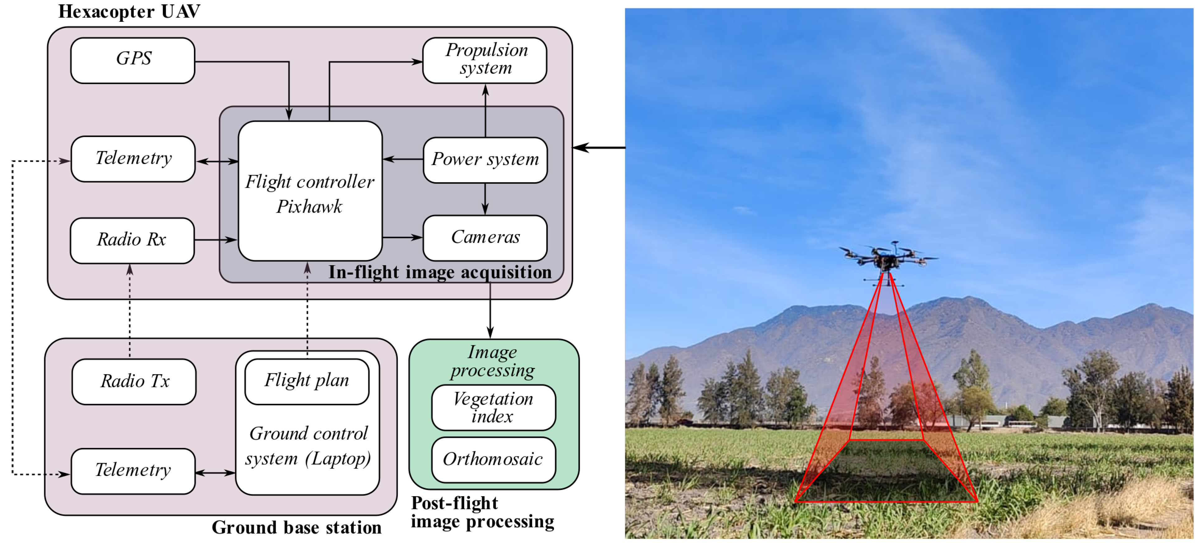
Figure 2 shows the scheme of the hexacopter UAV platform, the in-flight image acquisition, and the post-flight image processing blocks. The in-flight image acquisition is carried out when the vehicle flies over the field to be analyzed. It comprises two cameras that take images when a signal is received from the flight controller. Post-flight image processing is achieved by processing flight data. It consists of applying image processing algorithms to obtain the vegetation index and the orthomosaic to analyze the field.

2.2. Hexacopter UAV Dynamics Model

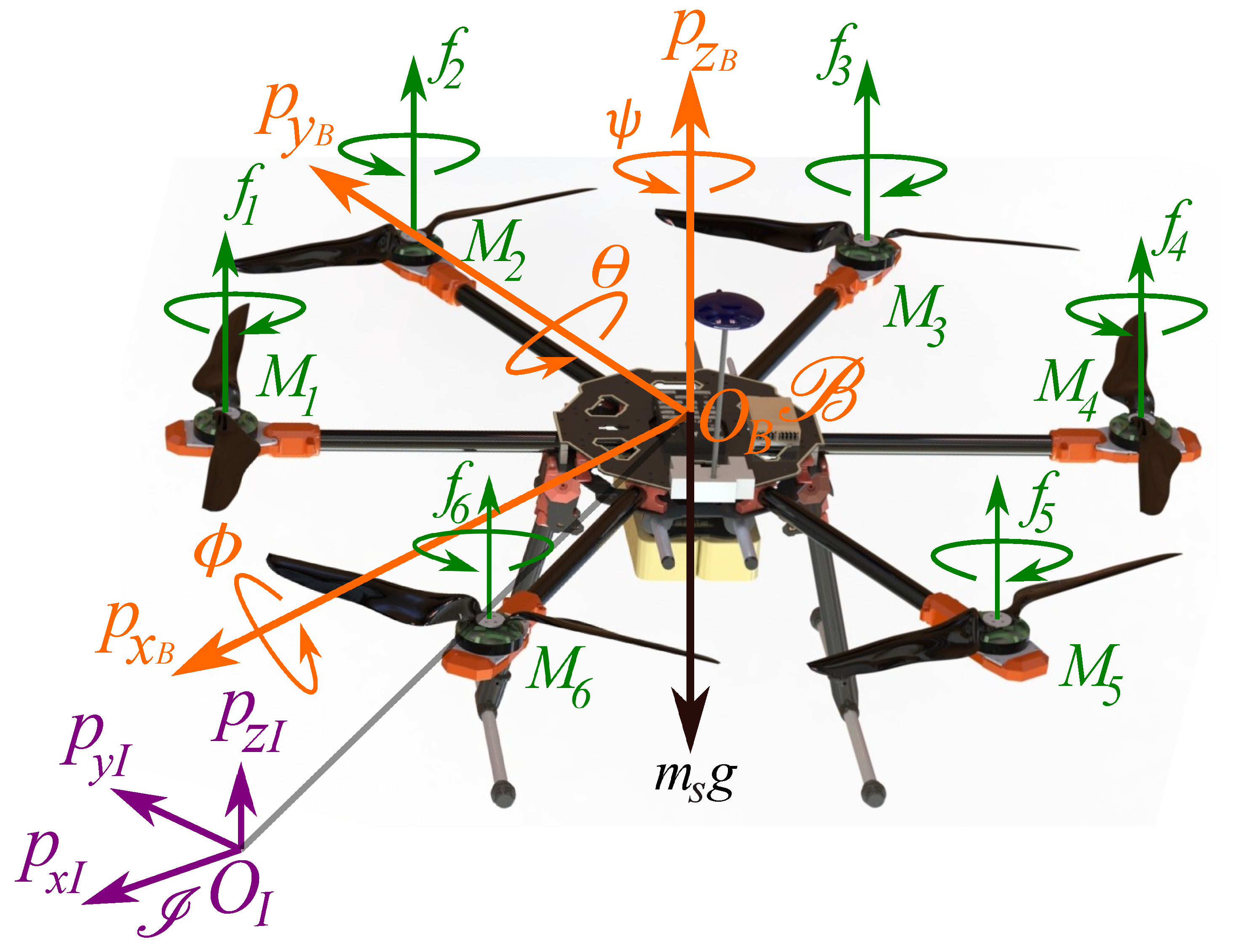
This section introduces the nonlinear dynamics model of the hexacopter aerial vehicle to design an effective fault-tolerant control strategy. Figure 3 illustrates the hexacopter scheme, showing the main forces acting on the vehicle, with the corresponding parameters listed in Table 2. The following assumptions are made to derive the dynamic model: the quadcopter structure is rigid and symmetrical, the center of mass coincides with the origin of the body frame O B , and the propellers are rigid.
The hexacopter consists of six independent motors, each with a propeller that generates torques and thrusts along the propellers’ axis of rotation. Propellers 1 , 3 and 5 rotate clockwise, while propellers 2 , 4 and 6 rotate counterclockwise, as shown in Figure 3. In this figure, I = { O I , p x I , p y I , p z I } represents an inertial frame, and B = { O B , p x B , p y B , p z B } represents a rigid frame attached to the vehicle’s center of mass.
The dynamics of the hexacopter can be described as follows:
ξ ˙ ( t ) = v ( t ) , m s v ˙ ( t ) = R s ( t ) F ( t ) , R ˙ s ( t ) = R s ( t ) Ω ^ ( t ) , J Ω ˙ ( t ) = Ω ( t ) × J Ω ( t ) + τ ( t ) ,
where t denotes time, ξ ( t ) = [ p x ( t ) , p y ( t ) , p z ( t ) ] R 3 represents the position vector, and v ( t ) = [ v x ( t ) , v y ( t ) , v z ( t ) ] R 3 represents the velocity vector of the vehicle in the inertial frame I . The angular velocity in the body-fixed frame B is given by Ω ( t ) = [ p ( t ) , q ( t ) , r ( t ) ] R 3 , and m s denotes the vehicle’s total mass. The Euler angles are represented by roll ϕ ( t ) , pitch θ ( t ) , and yaw ψ ( t ) . The moment of inertia matrix is J = diag ( J x , J y , J z ) R 3 × 3 in frame B , with τ ( t ) representing the moments in B . The matrix Ω ^ ( t ) is the skew-symmetric of Ω ( t ) , R s ( t ) is the rotation matrix from B to I , and F ( t ) denotes the forces generated by the motors. Based on the given assumptions and using the Newton–Euler formalism, (1) can be formulated as follows:
p ˙ x ( t ) = v x ( t ) ,
p ˙ y ( t ) = v y ( t ) ,
p ˙ z ( t ) = v z ( t ) ,
v ˙ x ( t ) = c ψ ( t ) s θ ( t ) c ϕ ( t ) + s ψ ( t ) s ϕ ( t ) 1 m s u z ( t ) d f m s v x ( t ) ,
v ˙ y ( t ) = s ψ ( t ) s θ ( t ) c ϕ ( t ) c ψ ( t ) s ϕ ( t ) 1 m s u z ( t ) d f m s v y ( t ) ,
v ˙ z ( t ) = g + c θ ( t ) c ϕ ( t ) 1 m s u z ( t ) d f m s v z ( t ) ,
ϕ ˙ ( t ) = p ( t ) + s ϕ ( t ) t θ ( t ) q ( t ) + c ϕ ( t ) t θ ( t ) r ( t ) ,
θ ˙ ( t ) = c ϕ ( t ) q ( t ) s ϕ ( t ) r ( t ) ,
ψ ˙ ( t ) = s ϕ ( t ) q ( t ) + c ϕ ( t ) r ( t ) 1 c θ ( t ) ,
p ˙ ( t ) = q ( t ) r ( t ) ( J y J z ) + u ϕ ( t ) 1 J x d t J x p ( t ) ,
q ˙ ( t ) = p ( t ) r ( t ) ( J z J x ) + u θ ( t ) 1 J y d t J y q ( t ) ,
r ˙ ( t ) = p ( t ) q ( t ) ( J x J y ) + u ψ ( t ) 1 J z d t J z r ( t ) ,
where s , c and t correspond to the trigonometric functions sine , cosine and tangent , respectively. The state vector is given by x ( t ) = [ p x ( t ) , p y ( t ) , p z ( t ) , v x ( t ) , v y ( t ) , v z ( t ) , ϕ ( t ) , θ ( t ) , ψ ( t ) , p ( t ) , q ( t ) , r ( t ) ] while the system inputs for translational and attitude dynamics are denoted by u ( t ) = [ u z ( t ) , u ϕ ( t ) , u θ ( t ) , u ψ ( t ) ] . The actual inputs acting on the system are the upward-lifting forces generated by each propeller, represented as f ¯ ( t ) = [ f 1 ( t ) , f 2 ( t ) , , f 6 ( t ) ] , where each lifting force is saturated as f i [ 0 , f m a x ] , with i = 1 , , 6 (see Figure 3). According to the geometry of the hexacopter presented in Figure 3, the mapping from the rotor lift f i to the system total thrust and torque u ( t ) , also called the actuator mixer, is defined by:
u z ( t ) u ϕ ( t ) u θ ( t ) u ψ ( t ) = η 1 η 2 η 3 η 4 η 5 η 6 0 3 2 η 2 l 3 2 η 3 l 0 3 2 η 5 l 3 2 η 6 l η 1 l 1 2 η 2 l 1 2 η 3 l η 4 l 1 2 η 5 l 1 2 η 6 l η 1 k u η 2 k u η 3 k u η 4 k u η 5 k u η 6 k u f 1 ( t ) f 2 ( t ) f 3 ( t ) f 4 ( t ) f 5 ( t ) f 6 ( t ) ,
where η ¯ = [ η 1 , η 2 , η 6 ] , with η i [ 0 , 1 ] as the effectiveness of the i-th actuator. If η i = 1 , then a total fault is presented in the i-th actuator, η i = 0 indicates that the i-th actuator is healthy, and η i = [ 0 , 1 ] indicates an LoE in the i-th actuator. The ratio between the reactive torque and the lift of the rotors is defined as k u , and l is the distance from the center of the rotor to the center of mass of the vehicle. It is considered that the force generated by each motor has the following first-order transfer function relation:
f m i ( t ) = w m s + w m f i ( t ) .
where f m i ( t ) are the true forces to be replaced in (3).

2.3. Fault-Tolerant Control System

The rapid dynamics of hexacopter UAV systems pose a challenge for promptly detecting faults and reconfiguring the system before a crash occurs. Our interest is in validating in a simulation the feasibility of the proposed FTC algorithm for hexacopter UAV systems fulfilling a trajectory for precision agriculture. In order to achieve this goal, a Fault Reconfiguration (FR) scheme is proposed. Figure 4 presents the overall fault-tolerant control architecture for the hexacopter UAV system. The Fault Reconfiguration is applied exclusively to the vehicle experiencing actuator failure. This scheme consists of three main components: (i) the hexacopter UAV system, (ii) the nominal controllers, and (iii) the actuator fault diagnosis, which includes fault detection, isolation, estimation, and the reconfiguration system. To simplify the validation procedure, we have chosen a pole placement feedback controller with an integrator comparator as the nominal position controller, altitude, and attitude nominal controllers. These nominal controllers are used to show the effectiveness of the proposed fault-tolerant control scheme when an actuator of the hexacopter fails. The analysis of nominal controllers and actuator fault diagnosis is not within the scope of this work; additional information can be found in [27,28].
Only the nominal controller is used when the vehicle is operating without faults. When an actuator fault occurs, the fault diagnosis system detects, isolates, and estimates the fault. Typically, a fault is detected when the fault estimation signal exceeds a predefined threshold value. The sign value of the fault estimation signal is utilized to isolate the actuator fault, as detailed in [27]. Finally, the proposed FTC law is computed with a control reconfiguration system that changes the nominal controller to a new controller. Actuator faults may result from damage to the propeller or the motor itself, both of which can reduce motor effectiveness and lead to a loss of controllability in the hexacopter. To assess the controllability of the vehicle under a fault condition, the Available Control Authority Index (ACAI) method, as proposed by [29], is utilized.
To describe the proposed fault-tolerant control system, let us suppose a fault in the actuator 2. The results of the ACAI controllability method by using the parameters shown Table 2 are presented in Table 3. According to this table, if ann LoE is presented, i.e., η 2 [ 0.1 , 0.9 ] , then the hexacopter UAV is controllable with ACAI > 0. In this case, a nominal controller is enough to stabilize the vehicle. Nevertheless, if a total fault occurs, η 2 = 0, the system is uncontrollable with ACAI ≤0. Table 3 also indicates that losing the controllability of yaw dynamics (ACAI without yaw) can be a viable solution to safely recover a hexacopter UAV experiencing an actuator failure, as ACAI-WY > 0 . This approach involves relinquishing control of the yaw angle and utilizing the remaining forces to maintain a constant horizontal spin.
By using η ¯ = [ 1 , 0 , 1 , 1 , 1 , 1 ] and f 2 ( t ) = 0 in (3), u ϕ ( t ) can be expressed considering the actuator fault as
u ϕ f ( t ) = 3 2 l f 3 ( t ) + 3 2 l f 5 ( t ) + 3 2 l f 6 ( t ) .
Now, a reduced control input vector is introduced as u ¯ ( t ) = [ u z f ( t ) , u θ f ( t ) , u ψ f ( t ) ] , where (3) is rewritten as
u z f ( t ) u θ f ( t ) u ψ f ( t ) = η 1 η 3 η 4 η 5 η 6 η 1 l 1 2 η 3 l η 4 l 1 2 η 5 l 1 2 η 6 l η 1 k u η 3 k u η 4 k u η 5 k u η 6 k u f 1 ( t ) f 3 ( t ) f 4 ( t ) f 5 ( t ) f 6 ( t ) .
This implies that
f 1 ( t ) = 3 14 u z f ( t ) + 8 21 l u θ f ( t ) 5 42 k u u ψ ( t ) ,
f 3 ( t ) = 1 7 u z f ( t ) 4 21 l u θ f ( t ) 4 21 k u u ψ f ( t ) ,
f 4 ( t ) = 3 14 u z f ( t ) 2 7 l u θ f ( t ) + 3 14 k u u ψ f ( t ) ,
f 5 ( t ) = 1 7 u z f ( t ) 4 21 l u θ f ( t ) 4 21 k u u ψ f ( t ) ,
f 6 ( t ) = 2 7 u z f ( t ) + 2 7 l u θ f ( t ) + 2 7 k u u ψ f ( t ) .
From (8) and (10) f 3 ( t ) = f 5 ( t ) , then (5) can be rewritten as follows:
u ϕ f ( t ) = 3 2 l f 6 ( t ) = 3 7 l u z f ( t ) + 3 7 u θ f ( t ) + 3 7 k u l u ψ f ( t ) ,
where (12) is the reduced input u ϕ ( t ) for the system (2) when a failure in the actuator 2 is presented. The same procedure could be carried out for any individual actuator failure. With this consideration, the yaw angle ψ ( t ) dynamics is ignored following the work presented by [30].
From (2), a new system can be obtained to design the controller for attitude and altitude dynamics by considering the state vector x ¯ ( t ) = [ ϕ ( t ) , θ ( t ) , p ( t ) , q ( t ) , r ( t ) , p z ( t ) , v z ( t ) ] and the reduced control input vector u ¯ = [ u z f ( t ) , u θ f ( t ) , u ψ f ( t ) ] as follows
x ¯ ˙ ( t ) = f x ¯ ( t ) + h x ¯ ( t ) u ¯ ( t ) ,
where
f ( x ¯ ( t ) ) = p ( t ) + s ϕ ( t ) t θ ( t ) q ( t ) + c ϕ ( t ) t θ ( t ) r ( t ) c ϕ ( t ) q ( t ) s ϕ ( t ) r ( t ) q ( t ) r ( t ) ( J y J z ) 1 J x d t J x p ( t ) p ( t ) r ( t ) ( J z J x ) 1 J y d t J y q ( t ) p ( t ) q ( t ) ( J x J y ) 1 J z d t J z r ( t ) v z ( t ) g d f m s v z ( t ) , h ( x ¯ ( t ) ) = 0 0 0 0 0 0 3 7 J x l 3 7 J x 3 7 k u J x l 0 1 J y 0 0 0 1 J z 0 0 0 c θ ( t ) c ϕ ( t ) 1 m s 0 0 .
Note that in (13), the states ϕ ( t ) , θ ( t ) and p z ( t ) are independent of u ¯ ( t ) . These states can be expressed as
f ¯ ( x ¯ ( t ) ) = ϕ ˙ ( t ) θ ˙ ( t ) p ˙ z ( t ) = p ( t ) + s ϕ ( t ) t θ ( t ) q ( t ) + c ϕ ( t ) t θ ( t ) r ( t ) c ϕ ( t ) q ( t ) s ϕ ( t ) r ( t ) v z ( t ) .
The derivative of f ¯ ( x ¯ ( t ) ) can be calculated as follows:
d f ¯ x ¯ ( t ) d t = ϕ ¨ ( t ) θ ¨ ( t ) p ¨ z ( t ) = f ¯ x ¯ ( t ) x ¯ ( t ) x ¯ ˙ ( t ) = J ¯ x ¯ ( t ) x ¯ ˙ ( t ) ,
where J ¯ ( x ¯ ( t ) ) is the Jacobian matrix. Then, by substituting (13) into (15) for x ¯ ˙ ( t ) , the following equation can be obtained:
ϕ ¨ ( t ) θ ¨ ( t ) p ¨ z ( t ) = J ¯ x ¯ ( t ) f x ¯ ( t ) + J ¯ x ¯ ( t ) h x ¯ ( t ) u ¯ ( t ) ,
where
J ¯ ( x ¯ ( t ) ) = f ¯ x ¯ ( t ) x ¯ ( t ) = q ( t ) c ϕ ( t ) t θ ( t ) r ( t ) s ϕ ( t ) t θ ( t ) r ( t ) c ϕ ( t ) q ( t ) s ϕ ( t ) 0 r ( t ) c ϕ ( t ) t θ 2 ( t ) + 1 + q ( t ) s ϕ ( t ) t θ 2 ( t ) + 1 0 0 1 0 0 s ϕ ( t ) t θ ( t ) c ϕ ( t ) 0 c ϕ ( t ) t θ ( t ) s ϕ ( t ) 0 0 0 0 0 0 1 .

2.3.1. Attitude and Altitude Controller

In order to design a tracking trajectory controller for attitude and altitude dynamics, the following errors can be defined:
e 1 ( t ) e 2 ( t ) e 3 ( t ) e 4 ( t ) e 5 ( t ) e 6 ( t ) = ϕ ( t ) ϕ d ( t ) ϕ ˙ ( t ) ϕ ˙ d ( t ) + k 1 e 1 ( t ) θ ( t ) θ d ( t ) θ ˙ ( t ) θ ˙ d ( t ) + k 3 e 3 ( t ) p z ( t ) p z d ( t ) p ˙ z ( t ) p ˙ z d ( t ) + k 5 e 5 ( t ) , ,
where k 1 , k 3 , and k 5 are positive constant control gains and the subscript d indicates the desired reference. Therefore, the error dynamics of (17) is as follows:
e ˙ 1 ( t ) = e 2 ( t ) k 1 e 1 ( t ) , e ˙ 3 ( t ) = e 4 ( t ) k 3 e 3 ( t ) , e ˙ 5 ( t ) = e 6 ( t ) k 5 e 5 ( t ) .
The tracking trajectory’s objective is to design a controller for the tracking errors (17) that force the altitude and attitude subsystems to the desired reference. Based on (19) and the above control objective, the following control inputs are established:
u ¯ ( t ) = J ¯ ( x ¯ ( t ) h x ¯ ( t ) ) 1 J ¯ x ¯ ( t ) f x ¯ ( t ) J ¯ x ¯ ( t ) h x ¯ ( t ) 1 ( k 1 2 1 ) e 1 ( t ) ( k 1 + k 2 ) e 2 ( t ) + ϕ ¨ d ( t ) ( k 3 2 1 ) e 3 ( t ) ( k 3 + k 4 ) e 4 ( t ) + θ ¨ d ( t ) ( k 5 2 1 ) e 5 ( t ) ( k 5 + k 6 ) e 6 ( t ) + p ¨ z d ( t ) ,
where k 2 , k 4 and k 6 are positive constants gains. Thus, the following theorem can be formulated to guarantee the stability of the tracking errors (17):
Theorem 1.
The attitude dynamics (2c) and (2f), and the attitude dynamics (2g), (2h), and (2j)–(2l), applying the control input vector (19), converge to the desired reference in the sense that the tracking errors (17) are exponentially stable if the control gains k j , with j = 1 , , 6 , are positive.
Proof. 
Let us choose the following candidate quadratic Lyapunov function as
V 1 = 1 2 j = 1 6 e j 2 ( t ) .
Then, the time derivative of the function (20) is given by
V ˙ 1 = j = 1 6 e j ( t ) e ˙ j ( t ) .
By substituting (18) into (21), the following derivative of V 1 is deduced:
V ˙ 1 = e 1 ( t ) e 2 ( t ) k 1 e 1 ( t ) + e 2 ( t ) ϕ ¨ ( t ) ϕ ¨ d ( t ) + k 1 ( e 2 ( t ) k 1 e 1 ( t ) ) + e 3 ( t ) e 4 ( t ) k 3 e 3 ( t ) + e 4 θ ¨ ( t ) θ ¨ d ( t ) + k 3 ( e 4 ( t ) k 3 e 3 ( t ) ) + e 5 ( t ) e 6 ( t ) k 5 e 5 ( t ) + e 6 p ¨ z ( t ) p ¨ z d ( t ) + k 5 ( e 6 ( t ) k 5 e 5 ( t ) ) .
Substituting the time derivatives of ϕ ˙ , θ ˙ and p ˙ z from (2f) and (2j)–(2l) into (22) with the control inputs (19), the derivative of the Lyapunov function (22) is rewritten as follows:
V ˙ 1 = j = 1 6 k j e j 2 ( t ) .
Now, by choosing the control gains k j > 0 , with j = 1 , , 6 in (23), then V ˙ 1 0 , and the altitude and attitude tracking errors (17) are exponentially stable. □

2.3.2. Translational Controller

The translational dynamics (2d) and (2e) can be expressed as
p ¨ x ( t ) p ¨ y ( t ) = R ψ s ϕ ( t ) s θ ( t ) c ϕ ( t ) 1 m s u z f ( t ) d f m s v x ( t ) d f m s v y ( t ) ,
with
R ψ = s ψ ( t ) c ψ ( t ) c ψ ( t ) s ψ ( t ) ,
where [ p ¨ x ( t ) , p ¨ y ( t ) ] = [ v ˙ x ( t ) , v ˙ y ( t ) ] .
The errors for the translational subsystem (2a), (2b), (2d) and (2e) are defined as
e 7 ( t ) e 8 ( t ) e 9 ( t ) e 10 ( t ) = p x ( t ) p x d ( t ) p ˙ x ( t ) p ˙ x d ( t ) + k 7 e 7 ( t ) p y ( t ) p y d ( t ) p ˙ y ( t ) p ˙ y d ( t ) + k 9 e 9 ( t ) ,
where k 7 and k 9 are positive constant gains. The error dynamics of (25) is as follows:
e ˙ 7 ( t ) = e 8 ( t ) k 7 e 7 ( t ) , e ˙ 9 ( t ) = e 10 ( t ) k 9 e 9 ( t ) ,
Now, to design the translational controller ensuring that the tracking errors (25) converge to zero, the following Equation (27) is stated by solving for [ s ϕ ( t ) , s θ ( t ) c ϕ ( t ) ] in (24) as a desired roll and pitch dynamics and by considering small angles, i.e., s ϕ d ( t ) ϕ d ( t ) and c ϕ d ( t ) 1 . Then ϕ d ( t ) and θ d ( t ) are chosen as
ϕ d ( t ) θ d ( t ) = R ψ m s u z f ( t ) ( k 7 1 ) e 7 ( t ) ( k 7 + k 8 ) e 8 ( t ) + p ¨ x d ( t ) ( k 9 1 ) e 9 ( t ) ( k 9 + k 10 ) e 10 ( t ) + p ¨ y d ( t ) + d f m s v x ( t ) d f m s v y ( t ) ,
where k 8 and k 10 are positive constant gains. The following theorem is stated to ensure the stability of the translational tracking errors (25).
Theorem 2.
The translational dynamics (2a), (2b), and (24) converge to the desired reference in the sense that the tracking errors (25) are exponentially stable if the control gains k j , with j = 7 , , 9 , are positive.
Proof. 
The proof follows the same steps as in the proof of Theorem 1 and is not given here for compactness of the presentation. □

2.4. Validation of the Fault-Tolerant Control Scheme

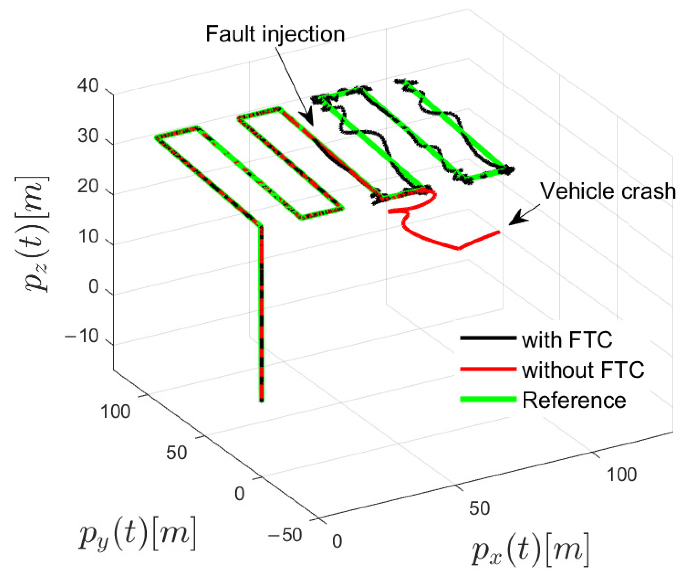
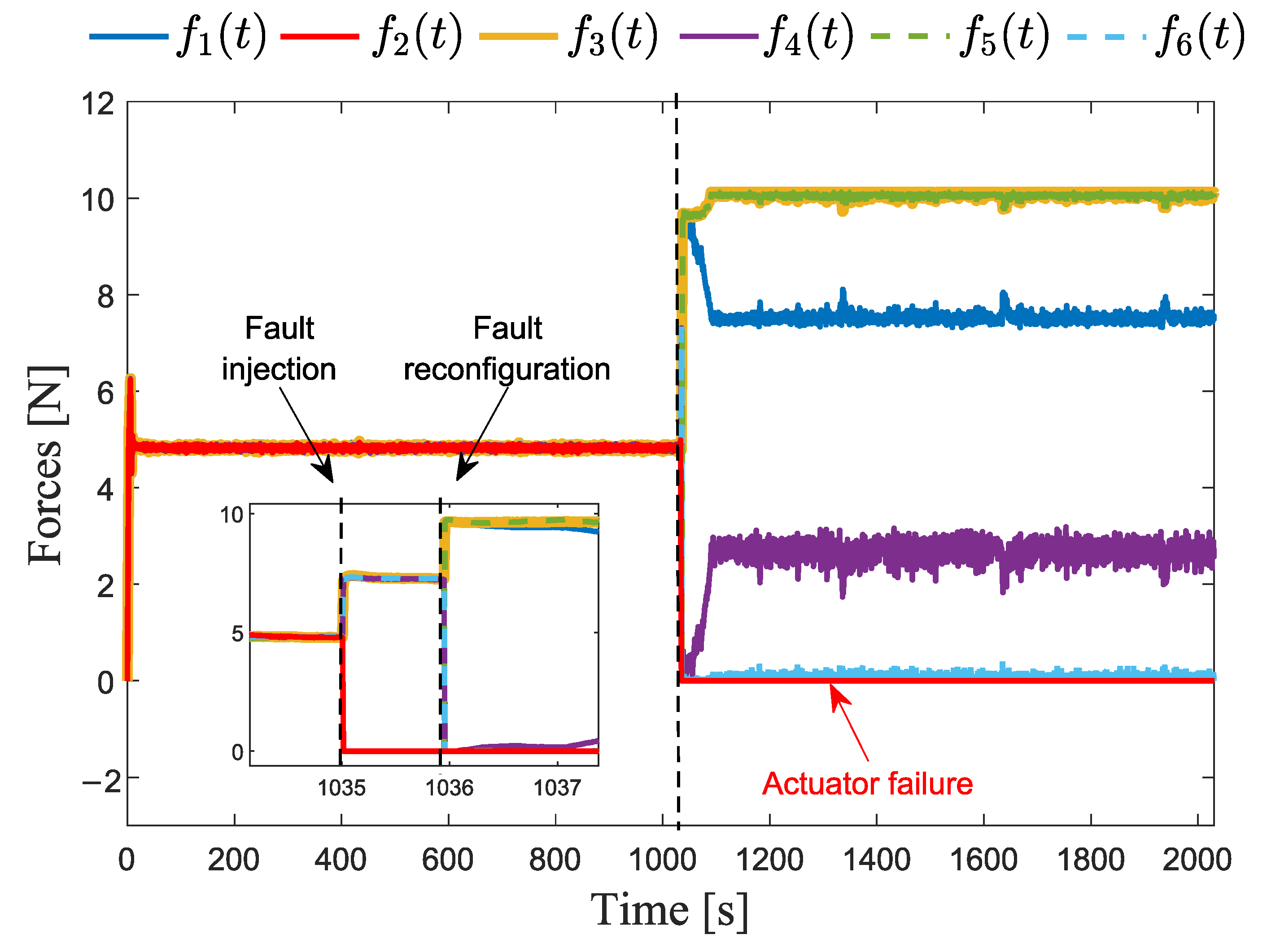
In order to show the feasibility of the proposed fault-tolerant control algorithm in the hexacopter UAV suffering an actuator failure, an agriculture flight planning is developed. In this validation, an actuator failure in motor 2 is introduced at time 1035 s while the hexacopter is flying along a predefined path at a non-hover position. Before the failure, the vehicle operates with the nominal controllers. Upon detecting and isolating the fault, the nominal controllers are replaced with the proposed position, altitude, and attitude controllers, utilizing information from the fault diagnosis system, as illustrated in Figure 5, Figure 6 and Figure 7.
The gains used in the attitude and altitude controllers are k 1 = k 3 = 1 , k 5 = 1.5 , k 2 = k 4 = 0.85 , and k 6 = 0.3 . The gains for the translational controller are k 7 = k 9 = 2 and k 8 = k 10 = 0.3 . We impose that the fault is detected and isolated after 1 s of occurrence (see Figure 7). Sensor noise was introduced using a random function with a normal distribution, with a standard deviation of 0.005 and a mean of zero.
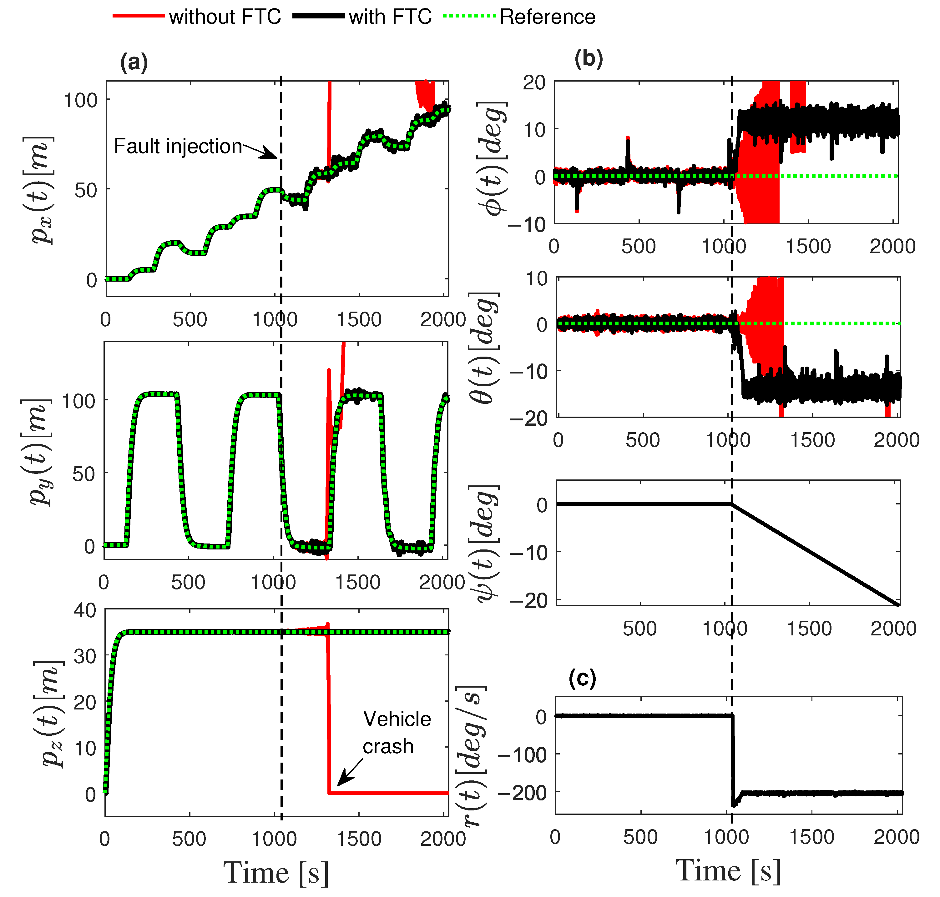
Figure 5 depicts a 3-D position comparison of the hexacopter vehicle. This figure illustrates that without an FTC strategy, the hexacopter crashes to the ground. In contrast, the FTC system enables the vehicle to complete its path successfully. Furthermore, Figure 6 shows the position and attitude dynamics. Figure 6b presents the roll ϕ ( t ) and pitch θ ( t ) angles, which remain around zero, indicating a stable flight even in the presence of an actuator failure. When the FTC strategy is applied, the roll and pitch angles are around 15 degrees with stable dynamics, indicating that the failure is reconfigured. Additionally, Figure 6b shows that the yaw angle varies due to the uncontrolled state. Figure 6c displays the vehicle’s yaw angular velocity r ( t ) during the flight test. Once fault f 2 is detected and isolated, the attitude controller induces a constant yaw rotation at a velocity of r ( t ) = 200 deg/s, as shown in Figure 6c.
Figure 7 illustrates the forces produced by the motors when the FTC algorithm is applied. It is evident that when the failure is introduced in motor 2, f 2 , the motor opposite f 5 reduces its force to compensate. This adjustment continues with the nominal controller until the failure is detected and isolated. When the Fault Reconfiguration is applied, the opposite motor f 5 increases its magnitude to compensate for the failure. The remaining motors f 3 and f 1 also increase their forces while f 6 and f 4 reduce their forces quickly to achieve the required yaw velocity dynamics. After reconfiguring for the failure, the hexacopter UAV successfully follows the desired path without incurring any damage.
The following subsections will discuss the application of various advanced technologies in precision agriculture. This will include in-flight image acquisition and flight path planning for efficient data collection and field coverage. Additionally, the estimation of near-infrared reflectance to generate the normalized difference vegetation index and assess crop health will be explored. Finally, the application will be carried out on sugarcane crops during their tillering stage.

2.5. In-Flight Image Acquisition

2.5.1. Digital Camera

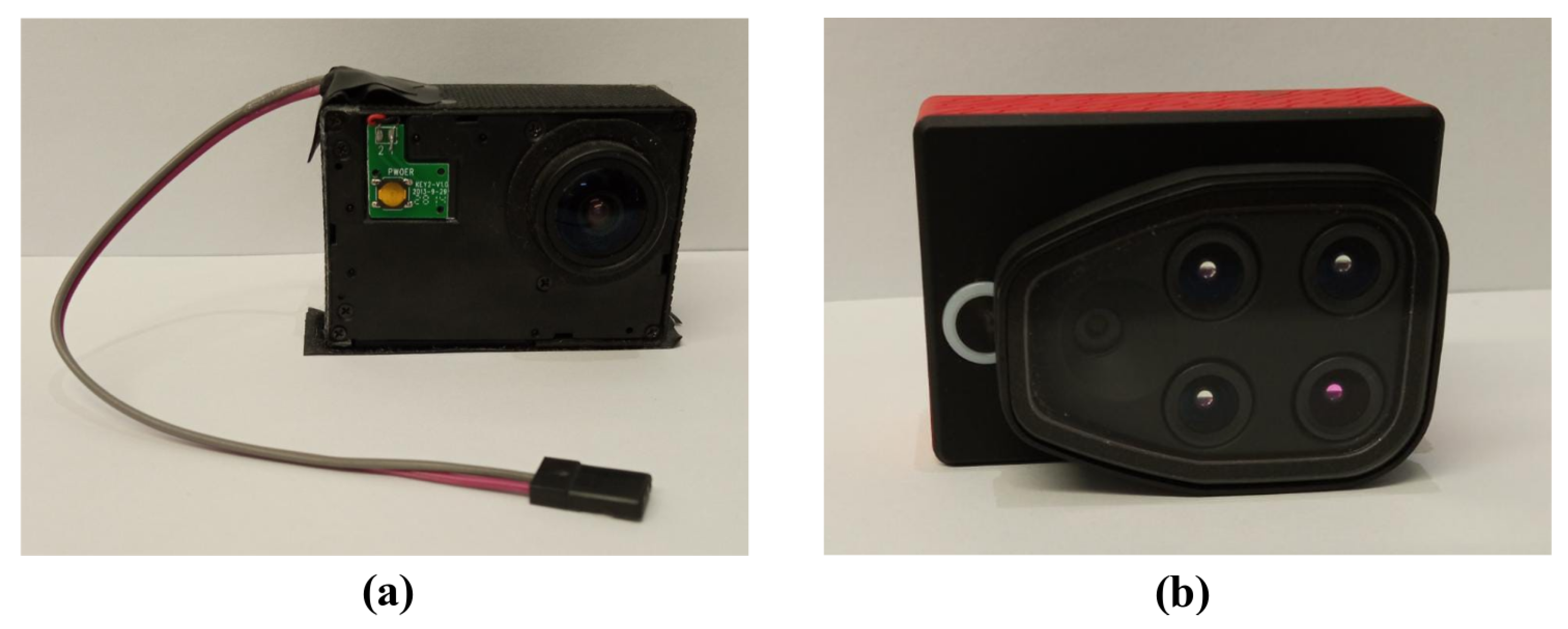
The SJ9000 camera used in this study was sourced from SJCAM, Shenzhen, China. The SJ9000 camera is chosen to collect the red–green–blue (RGB) imagining data because of the light weight and low cost of this type of camera (see Figure 8a). Low-cost action cameras, like a standard digital camera, have a Bayer color filter that allows capturing an RGB color image. The SJ9000 camera is equipped with an Aptina AR0330 CMOS sensor, the optical format is 1 / 3 -inch, and the sensor size is 4.51 mm × 3.6 mm, defined as I x and I y , respectively. The image size of this camera is 4032 × 460 pixels, defined as L x and L y . The focal length f c of the digital camera is 2.55 mm.
The digital camera is limited to visual bands, that is, visible red, green, and blue information. These cameras are used to detect plants’ outer defects, greenness, and growth monitoring. In addition, they are applied to calculate a range of vegetation indices to create high-resolution digital elevation models and vegetation height maps [31]. Furthermore, in this work, the proposed photographs for mapping are achieved by using the SJ9000 single-lens frame camera because it provides high geometric picture quality. The autopilot Pixhawk was used to control the camera trigger. The autopilot detects a trigger event and proceeds to capture the images with a predefined time T s according to the camera characteristics and flight velocity v m a x . The SJ9000 camera was modified by adding an electronic switch circuit to digitally press the image capture button when the trigger event is detected from the autopilot, as shown in Figure 8a.

2.5.2. Multispectral Camera

A Parrot Sequoia camera mounted on the hexacopter UAV was used to acquire multispectral data (see Figure 8b). This camera has five separate imaging sensors with a global shutter, including four multispectral sensors and one RGB sensor. A sunshine sensor is included that is positioned on top of the UAV, so the Parrot Sequoia camera can be used in clear and overcast conditions. The multispectral sensors capture images in the green (G, 530–570 nm), red (R, 640–680 nm), red-edge (RE, 730–740 nm), and near-infrared (NIR, 770–810 nm) wavelength bands. The focal length of the Sequoia camera is 3.98 mm with an image size of 1280 × 960 pixels and a sensor size of 4.8 mm × 3.6 mm.

2.6. Data Collection and Flight Planning

2.6.1. Camera Model

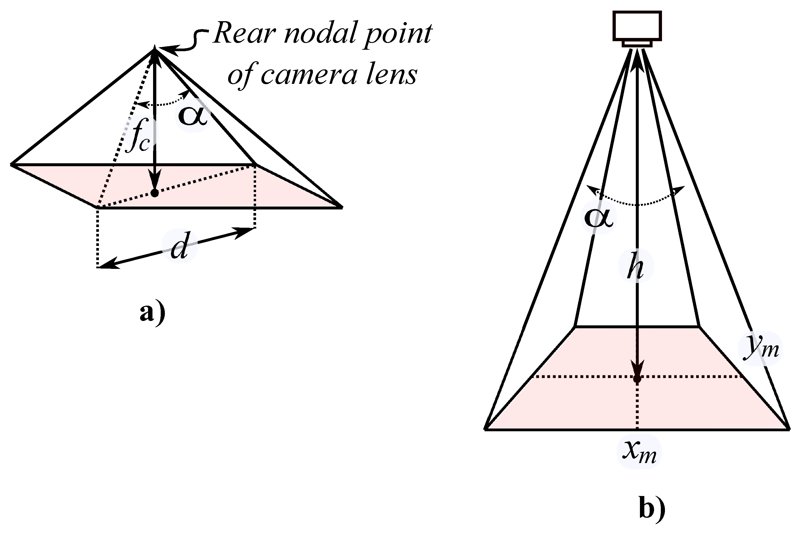
The goal of our mission is to generate the photogrammetry image by scanning a given area with the digital camera and to extract multispectral data in order to evaluate different vegetation indexes with the Sequoia camera. Camera parameters can be used to calculate the projection area and the image dimensions. The angular field of view is the angle α subtended at the rear nodal point of the camera lens by the diagonal d of the picture format, as illustrated in Figure 9a.
The focal length of a camera measures the distance between the nodal point of the lens and the camera sensor, and it is expressed by f c in millimeters. Image resolution L x and L y , are expressed in pixels for both sides of the image. Then, the angular field of view α can be calculated as follows [32]:
α = 2 tan 1 d 2 f c .
The distance is defined as d = I x 2 + I y 2 , where I x and I y are the image format size, expressed in millimeters. From Figure 9b and [33], the projection area can be calculated by assuming that the camera is parallel to the ground at a defined height h, as follows:
x m = 2 h tan α 2 , y m = x m L y L x .
Spatial resolution R is used in order to calculate the maximum height h m a x that the hexacopter UAV can fly, applying the following equations:
R = L x x m = L x 2 h tan α 2 .
Then, by using (30), h m a x is calculated by
h m a x = L x 2 R tan α 2 .
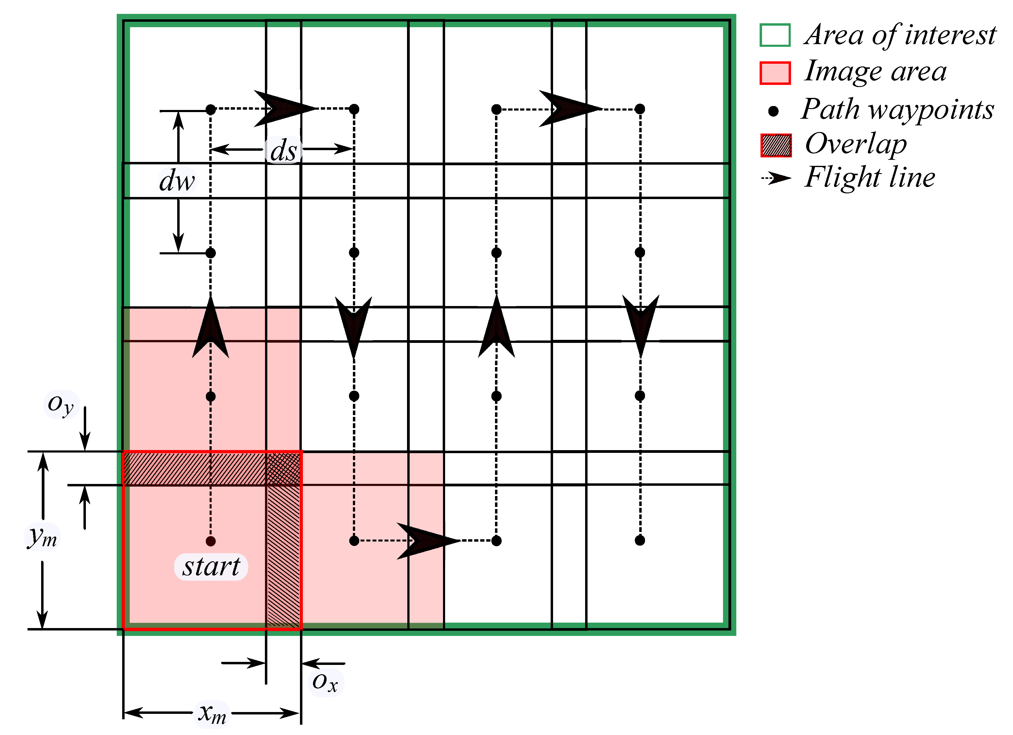
The reconstruction of the area of interest is achieved by using the parameters presented in Figure 10. This figure shows the waypoints and the flight trajectory that the hexacopter UAV needs to follow. The area of interest is decomposed into rectangles of size x m and y m . The vehicle path must be programmed to follow the center of those rectangles. To generate a correct photogrammetric image, the acquired images must be overlapping, as illustrated in Figure 10, with o x and o y as horizontal and vertical overlaps, respectively. The horizontal distance between two horizontal points is defined by d s = x m o x , and the vertical distances between two vertical points are represented as d w = y m o y . By considering the percentage of overlap ( o x p , o y p ), d s and d w can be computed as follows [32]:
d s = x m 1 o x p 100 , d w = y m 1 o y p 100 .
The maximum speed v m a x of the hexacopter UAV can be calculated by using the interval between two consecutive shots of the camera T s and the minimum specified overlap defined by the distance between two points of the path planning ( d s or d w ) : v m a x T s d w . Therefore the maximum speed of the vehicle can be defined as:
v m a x = y m T s 1 o y p 100 .
The limitation of the hexacopter UAV flight altitude depends on the camera’s characteristics used for data acquisition. This is an inherent limitation when performing data collection tasks with digital and multispectral cameras using UAVs. The maximum altitude and speed are the recommended values.
Note that weather conditions, such as wind, are not explicitly considered in the flight planning. However, the designed controllers are sufficiently robust due to the integrators included to handle such disturbances.

2.6.2. Estimation of Agricultural Near-Infrared Images from RGB Data

Usually, the near-infrared (NIR) band is used in precision agriculture to create the Normalized Difference Vegetation Index (NDVI) map that can provide the identification of damaged vegetation areas, monitoring plant growth and chlorophyll levels [34]. The NDVI is calculated using NIR and red band (R), as follows [35]:
N D V I = N I R R N I R + R ,
where N I R and R are spectral radiance measurements recorded with sensors in red (visible) and near-infrared regions, respectively. NDVI produces values ranging from −1 to 1. Negative values typically represent water bodies, clouds, and areas without vegetation. Values close to 0 indicate bare soil or areas with little vegetation. Higher values (close to 1) indicate densely vegetated areas. Usually, the sensor used is a multispectral or hyperspectral camera, both of which are expensive. Based on [36], an approach method for NIR data estimation with only information from RGB images using deep learning Pix2Pix network [37] is proposed in this work.
Pix2Pix uses Generative Adversarial Networks (GANs) in the conditional setting, also called cGANs. This algorithm applies a condition on an input image and generates a corresponding output image for image-to-image translation tasks. The image-creating network is called the Generator (G), and the fake image identifier is called the Discriminator (D). The architecture of Pix2Pix is based on the U-Net convolutional network [38] as a generator model and the discriminator is a convolutional PatchGAN [39].
The objective of the cGAN is to learn a mapping from observed image x p and random noise vector z p , to the output image y p , and it is defined as [37]
L c G A N ( G , D ) = E x p , y p [ log D ( x p , y p ) ] + E x p , z p [ log ( 1 D x p , G ( x p , z p ) ] ,
where E x p , y p is the error between the input image and the ground truth image, and E x p , z p is the error between the input image and the generated image calculated by the discriminator D. The generator G tries to minimize the objective (35) against an adversarial D that tries to minimize the following objective:
G * = arg min G max D L c G A N ( G , D ) + λ L L 1 ( G ) ,
with
L L 1 ( G ) = E x p , y p , z p [ | | y G ( x p , z p ) | | ] ,
and λ is defined as the weight parameter to L L 1 ( G ) . The discriminator learns to classify fake and real images. Pix2Pix uses a real image to perform image-to-image translation training. Both the generator and discriminator use modules of the form convolution-BatchNorm-ReLu.
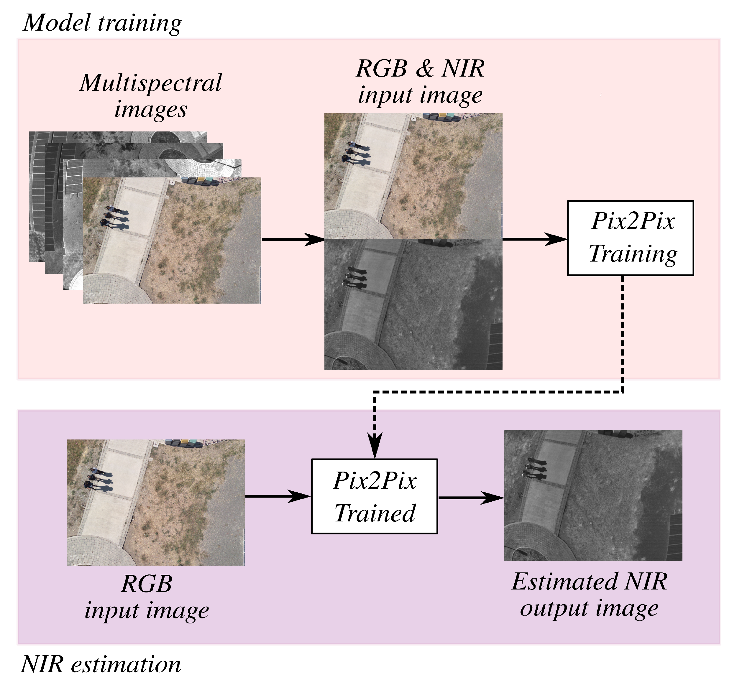
In this application, the real images are RGB-NIR samples. Initially, for training purposes, the RGB and NIR data were captured by the Sequoia multispectral camera. Once the training is complete, the input image is obtained from a low-cost RGB camera in order to validate the method for generating the NDVI map, as shown in Figure 11. This figure presents two main blocks: model training and NIR estimation. First, the multispectral images. Subsequently, only the real RGB and NIR images are extracted. These two images are then used to train the Pix2Pix neural networks. Once the system is trained, an input RGB image is applied to obtain the estimated output NIR image.
In the context of the Pix2Pix method, the RGB and NIR real images are initially misaligned due to the lens’s position in the multispectral camera. To address this, an alignment correction is implemented using rigid registration. This technique finds the optimal transformation (rotation and translation) that aligns one image to another, ensuring that the input and output images are correctly aligned for the Pix2Pix process. It also uses normalized cross-correlation to find the optimal alignment.
To evaluate the similarity between the real NIR and the estimated ones, the Structural Similarity Index (SSIM) [40] and the Peak Signal-to-Noise Ratio (PSNR) [41] are used. The SSIM is a metric used to assess the similarity between two images. It evaluates the pixel-wise differences and considers the structural information and luminance variations present in the images. The SSIM consists of three components: luminance L ( a , b ) , contrast C ( a , b ) , and structural S ( a , b ) comparison. The SSIM equation is represented as follows:
S S I M ( a , b ) = L ( a , b ) β C ( a , b ) γ S ( a , b ) δ = 2 μ a μ b + C 1 μ a 2 + μ b 2 + C 1 β 2 σ a σ b + C 2 σ a 2 + σ b 2 + C 2 γ σ a b + C 3 σ a σ b + C 3 δ ,
where a and b represent the local windows in the images; μ a and μ b are the means of a and b, respectively; σ a and σ b are the standard deviations of a and b, σ a b is the covariance of a and b, C 1 , C 2 and C 3 are small constants to stabilize the division with weak denominator, and β , γ and δ are constants to weight the relative importance of the components. The SSIM index ranges between 1 and 1, where 1 indicates perfect similarity. Higher values imply greater similarity between the images.
The PSNR is a commonly used metric for evaluating the quality of a compressed or restored image in relation to the original image. It is expressed in decibels and quantitatively measures how similar a compressed or restored image is to the original image. The equation for calculating PSNR is as follows:
P S N R = 10 log 10 M A X 2 M S E ,
where M A X is the maximum possible value in the original image, M S E is the Mean Squared Error, which is calculated as follows:
M S E = 1 m n i = 1 m j = 1 n | | f ( i , j ) g ( i , j ) | | 2 ,
where f is the original image, g is the compared image, and m and n and the number of rows and columns in pixels, respectively. A higher PSNR indicates less discrepancy between the images and, therefore, better quality of the compressed or restored image.

3. Results

For testing the effectiveness of the proposed strategy, two scenarios were considered. In the first scenario, the experimental flight planning, the data collection, and the orthomosaic generation are presented. In the second scenario, the estimation of the agricultural NIR band is established by using the digital camera. To clarify the research plan, Table 4 defines the parameters, including independent and dependent variables, crop type, and other relevant parameters for greater clarity in the study.

3.1. Scenario 1—Experimental Flight Planning and Data Collection

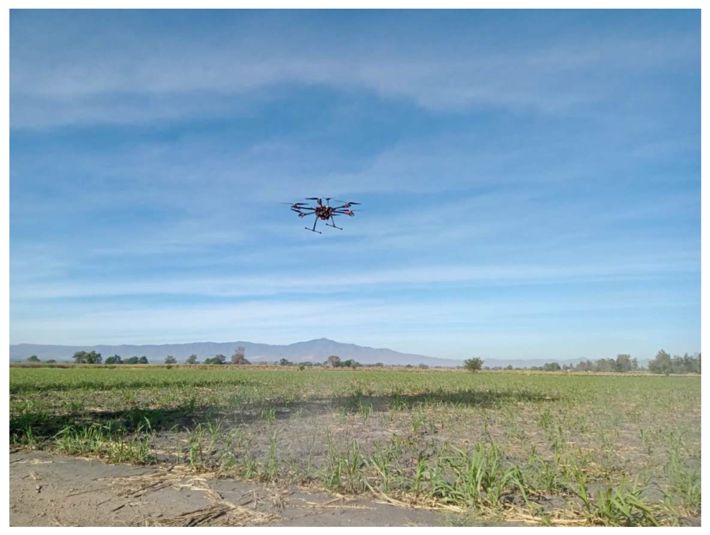
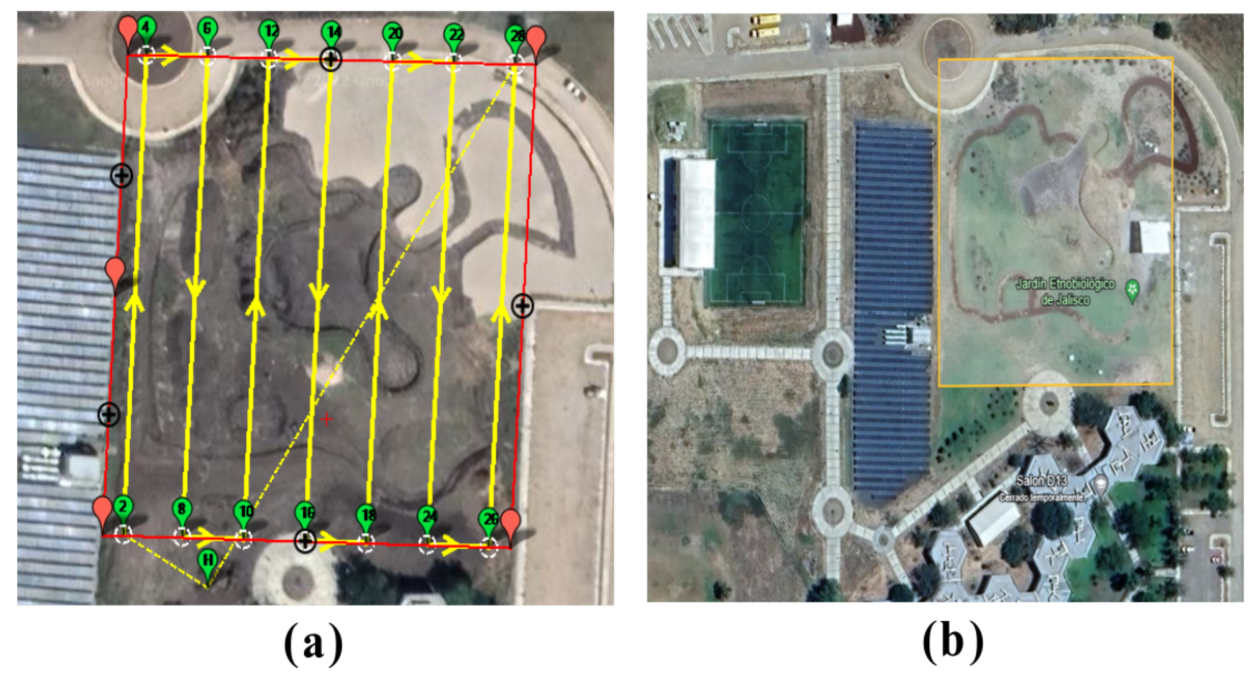
The experiments were conducted in Ameca Jalisco, Mexico, in August 2023. The flight planning and data collection were carried out experimentally by using the hexacopter UAV as shown in Figure 12. In this scenario, the vehicle performs a flight over the ethnobiological garden of Jalisco, located at the University of Guadalajara, Los Valles University Center. The area of interest is a rectangle with an area of 101 m × 104 m, as shown in Figure 13. The digital camera has an angular field of view α = 92.75 deg. The maximum height the hexacopter can fly is h m a x = 35 m, with the horizontal distance between two horizontal points d s = 14.68 m and the vertical distances d w = 11.01 m. The percentage of overlap is specified to o x p = o y p = 80 % (see Figure 13). According to these values, the maximum speed that the vehicle can fly is v m a x = 11.017 m/s. The images are captured from the autopilot with a predefined time of T s = 1 s. Also, the images are georeferenced with the onboard GPS data. The flight planning is designed with the above parameters and programmed into the hexacopter UAV using the Mission Planner ground station.
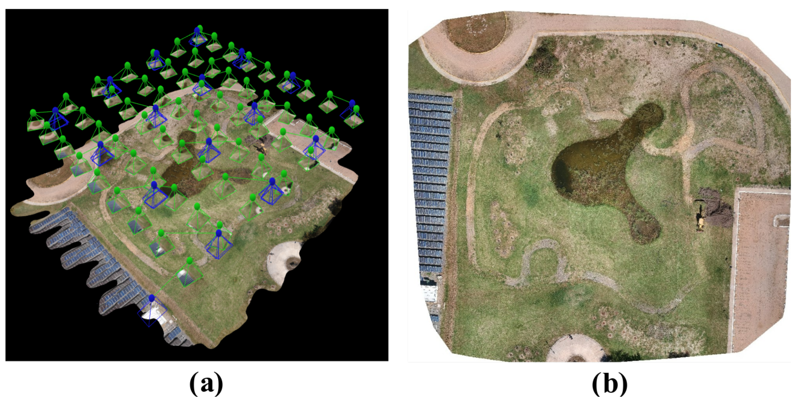
The trajectory and parameters allow the collection of 63 images to create the orthomosaic using the software PIX4D mapper version 4.5, as shown in Figure 14. From this figure, it is clear that successful reconstructions with an effective overlapping and correct attitude flight reference according to the computed flight planning. The proposed grid trajectory is accurate enough to generate a good-quality orthomosaic to create an effective NDVI map.

3.2. Scenario 2—Experimental Estimation of Agricultural NIR Band

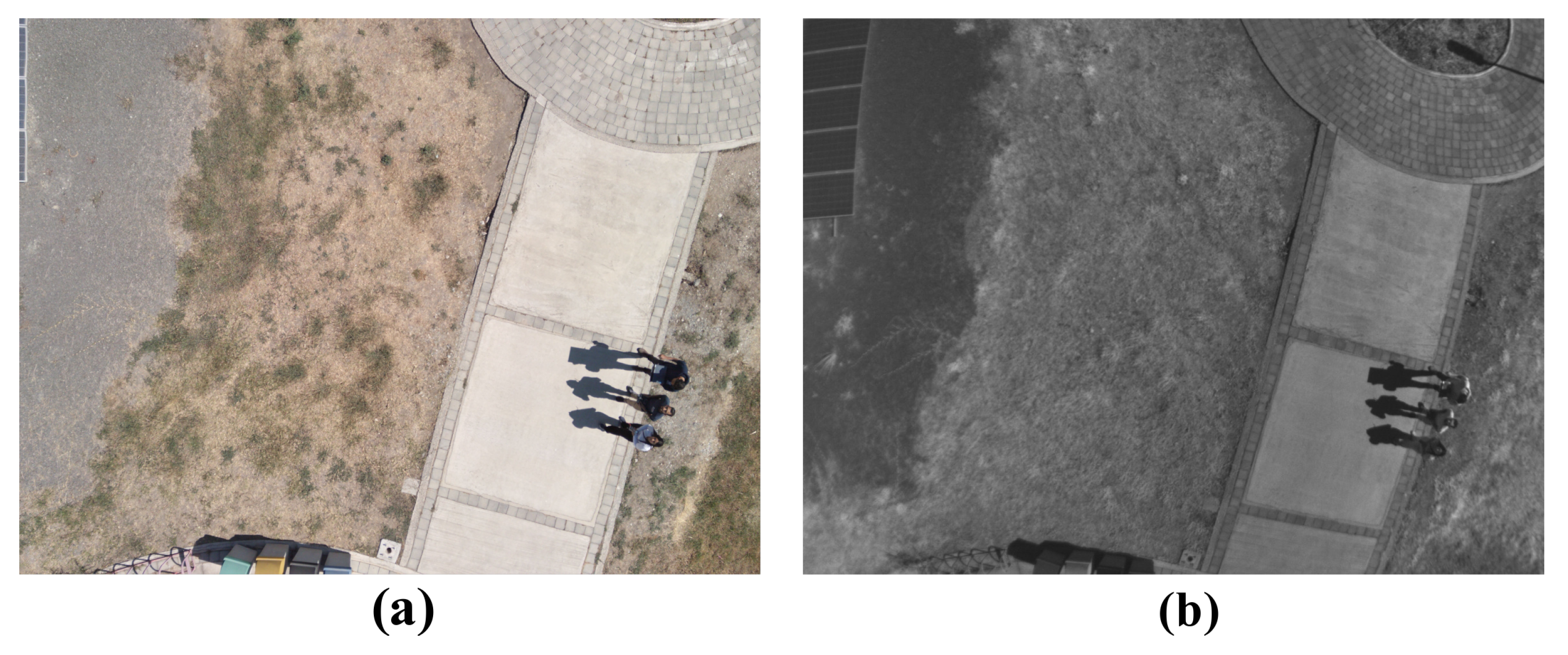
To perform the image-to-image translation training, Pix2Pix uses a pair of real images of RGB-NIR samples. The Sequoia multispectral camera generates five-band images captured experimentally on a flight by the hexacopter UAV. The flight was performed at the same altitude and velocity as the first scenario. The software MATLAB version 2023b is used to extract 256 × 256 pixels of the RGB-NIR samples. A total of 1080 RGB-NIR pairs were extracted for training the Pix2Pix network, and the validation was carried out with 400 pairs, as shown in Figure 15. Also, from Figure 15, it can be noted that both images are misaligned with each other due to the lens’s position in the multispectral camera. To correct this, the alignment correction is programmed in MATLAB by using rigid registration. The pix2Pix method was implemented in Python using Keras, OpenCV, and Tensorflow libraries. The Pix2Pix network was trained in 400 epochs with λ = 100 from (36). It used the Adam optimizing parameters.
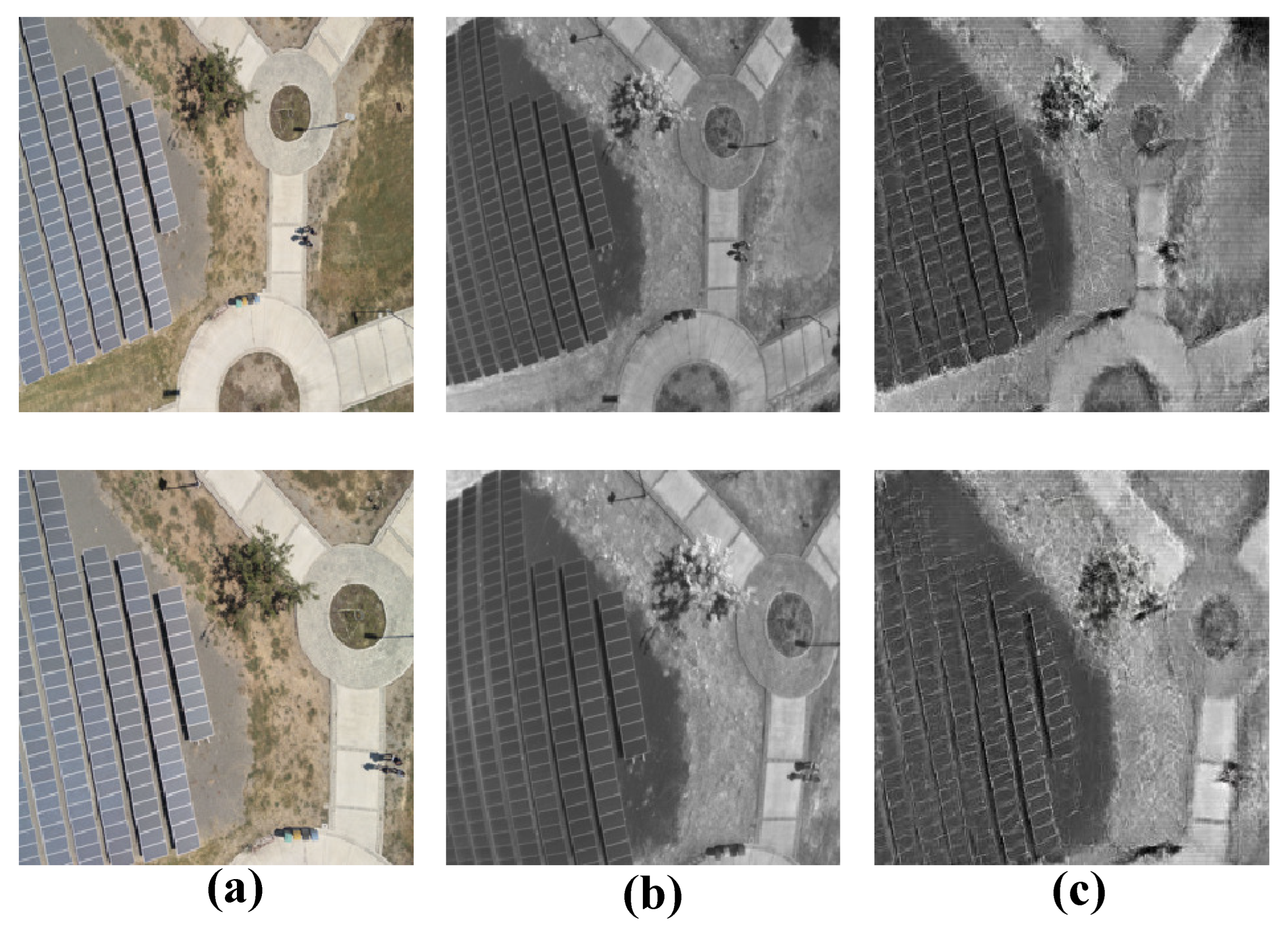
Figure 16 presents the estimated NIR images using the Pix2Pix method. For the estimation of the agricultural NIR band, Pix2Pix uses RGB images and NIR images as inputs from the multispectral camera. When the network is trained, a test is performed with an RGB image to obtain the estimated NIR data in order to validate the proposed method. Figure 16a and Figure 16b represent the real RGB and NIR input images, respectively. Figure 16c presents the estimated NIR image. The reader can observe in Figure 16 that the real NIR image is similar to the NIR estimated image. The network training can be observed from the following link: https://www.youtube.com/shorts/dHMd0389B64 (accessed on 25 July 2024).
Table 5 shows an SSIM value of 0.65 for image 1 and 0.53 for image 2. This indicates a moderate structural similarity between the images, meaning that while the images are not identical, they share significant common features. Additionally, if one of the images is a degraded or compressed version of the other, these SSIM values suggest that the degradation or compression has noticeably affected the image quality. Despite these differences, many important structures and visual details are still recognizable and similar between the images. From the same table, Table 5, negative PSNR values, such as 10.8 dB and 12.4 dB, indicate poor image quality. These values suggest that the reconstructed image is different from the original, with noise and distortion. However, these values are sufficient to construct an adequate normalized difference vegetation index.
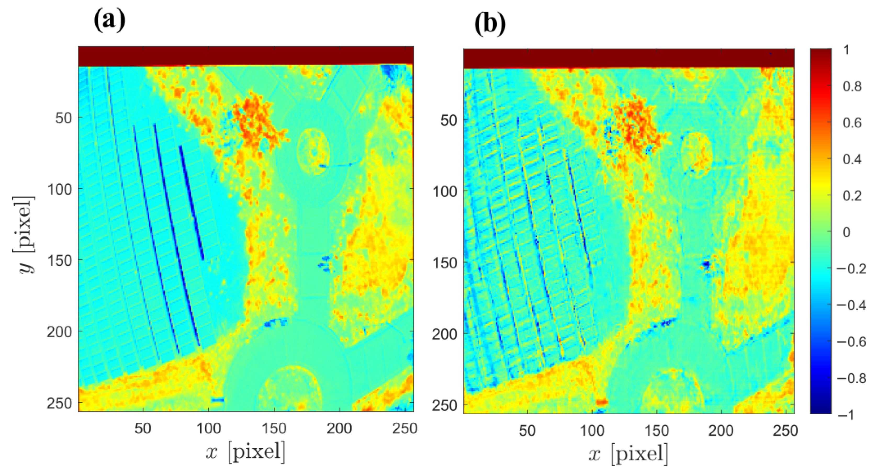
In order to show the effectiveness of the estimated NIR in constructing the NDVI, a comparison between the normalized index is generated with real NIR and with the estimated NIR image. Figure 17 displays two side-by-side maps of the NDVI, likely representing the same geographical area. Figure 17a is the NDVI constructed using the NIR image from the multispectral camera, while Figure 17b is the vegetation index created with the estimated NIR image. From this figure, negative values correspond to water, snow, clouds, or non-vegetated surfaces. Values close to zero generally represent rock, sand, or barren areas with little to no vegetation. Low positive values indicate shrubs and grasslands, and high values indicate temperate and tropical rainforests.
Also, Figure 17 exhibits a high degree of similarity. The consistent patterns and distribution of NDVI values across both maps indicate that the vegetation health and density characteristics are nearly identical between the two images. Given the strong similarity between the two NDVI maps, it is possible to derive the same set of information and conclusions about the vegetation health, density, and distribution from either image.
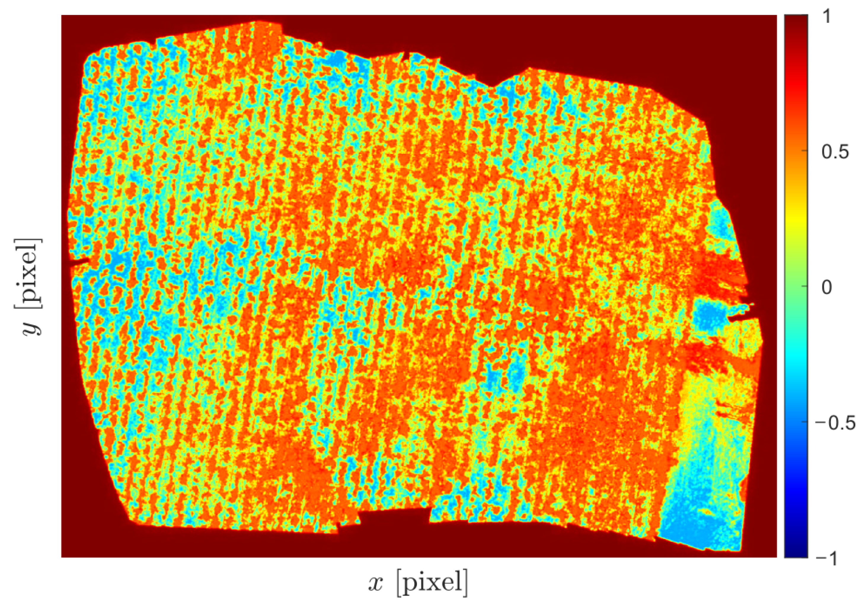
Furthermore, in Figure 18, the orthomosaic and the NDVI created from the estimated NIR applied to a sugarcane crop are presented. These experiments were conducted in Ameca, Jalisco, Mexico, during May 2023. In this experiment, a flight was performed over a sugarcane crop at the tillering stage. The area of interest is 1916 m2. Table 6 presents the NDVI values depending on the object type. It can be observed that areas close to 1 indicate dense vegetation, while areas close to 0 indicate bare soil or areas with little vegetation. The average NDVI value in the sugarcane planting area is 0.47 , indicating the tillering stage. The growing stages of the 12-month cycle of sugarcane are as follows: germination with a mean NDVI value of 0.35–0.4; tillering: 0.4–0.65; grand growth: 0.65–0.7; and ripening: 0.65–0.3 [42]. As a result, in Figure 18, we can identify the areas that require additional attention or intervention. These interventions may include targeted fertilization, irrigation adjustments, or pest and disease management to improve the overall health and yield of the sugarcane crop.

4. Conclusions

This paper proposed and validated an actuator fault-tolerant control strategy for a hexacopter UAV using advanced sensing techniques and flight trajectory planning for precision agriculture applications. The findings demonstrate that the proposed approach, which integrates NIR reflectance estimation from RGB imagery using the Pix2Pix deep learning network based on cGANs and NDVI calculation, enables effective crop health assessment. The NDVI was presented for a sugarcane crop using the estimated NIR to assess the crop’s condition during its tillering stage. The flight trajectory planning ensures the efficient coverage of the targeted agricultural area while considering the vehicle’s dynamics and fault-tolerant capabilities. Despite the limitations of UAV flight endurance and the need for robust data-processing algorithms, the study contributes to understanding FTC systems in precision agriculture. It highlights the importance of developing sophisticated strategies for adapting to changing environmental conditions. The results of this study can be applied to improve the reliability and efficiency of UAV-based data collection in agriculture.
The presented FTC scheme introduces several novel contributions. (i) Our FTC strategy not only can ensure fail-safe landing but also maintains operational efficiency and data collection accuracy even in the event of total actuator failures. This is particularly critical for precision agriculture applications where continuous data acquisition is essential. (ii) We have developed flight trajectory planning that ensures the efficient coverage of agricultural areas. This system takes into account the hexacopter dynamics and fault-tolerant capabilities, thus maximizing the effectiveness of the UAV’s operations. (iii) Our study specifically addresses fault-tolerant control during precision agriculture trajectories and in non-hover positions, a scenario that existing references do not fully cover. This ensures that the hexacopter can handle faults during actual mission operations, not just in stationary or hover modes.
Further research should focus on advancing energy management strategies, intelligent data fusion techniques, and standardized protocols to address the challenges posed by total actuator failures in hexacopter UAVs for precision agriculture applications.

Author Contributions

Conceptualization, G.O.-T. and J.Y.R.-M.; methodology, F.D.J.S.-V. and M.A.Z.-G.; software, J.J.G.A. and A.F.P.-V.; validation, M.B.R.-M. and E.M.P.; formal analysis, M.A.J.; investigation, G.O.-T.; resources, M.A.Z.-G. and J.J.G.A.; writing—original draft preparation, G.O.-T. and J.Y.R.-M.; funding acquisition, G.O.-T. All authors have read and agreed to the published version of the manuscript.

Funding

This research was funded by the Jalisco State Council of Science and Technology (COECyTJAL) by the Call for Proposals of the Jalisco Scientific Development Fund to Address Social Challenges 2022 (FODECIJAL 2022) with funding number 10105-2022.

Data Availability Statement

The original contributions presented in the study are included in the article, further inquiries can be directed to the corresponding author.

Acknowledgments

The authors would like to thank the Motion Capture Laboratory at the University of Guadalajara, Los Valles University Center, for granting access to their equipment and facilities.

Conflicts of Interest

The authors declare no conflicts of interest.

References

  1. Alzahrani, B.; Oubbati, O.S.; Barnawi, A.; Atiquzzaman, M.; Alghazzawi, D. UAV assistance paradigm: State-of-the-art in applications and challenges. J. Netw. Comput. Appl. 2020, 166, 102706. [Google Scholar] [CrossRef]
  2. Sadeghzadeh, I.; Zhang, Y. A review on fault-tolerant control for unmanned aerial vehicles (UAVs). In Proceedings of the Infotech@ Aerospace 2011, St. Louis, MO, USA, 29–31 March 2011; p. 1472. [Google Scholar]
  3. Fourlas, G.K.; Karras, G.C. A survey on fault diagnosis and fault-tolerant control methods for unmanned aerial vehicles. Machines 2021, 9, 197. [Google Scholar] [CrossRef]
  4. Saied, M.; Shraim, H.; Francis, C. A Review on Recent Development of Multirotor UAV Fault-Tolerant Control Systems. IEEE Aerosp. Electron. Syst. Mag. 2023, 1, 1–30. [Google Scholar] [CrossRef]
  5. Zhang, Y.; Jiang, J. Bibliographical review on reconfigurable fault-tolerant control systems. Annu. Rev. Control 2008, 32, 229–252. [Google Scholar] [CrossRef]
  6. Nguyen, D.T.; Saussie, D.; Saydy, L. Design and experimental validation of robust self-scheduled fault-tolerant control laws for a multicopter UAV. IEEE/ASME Trans. Mechatronics 2020, 26, 2548–2557. [Google Scholar] [CrossRef]
  7. Saied, M.; Lussier, B.; Fantoni, I.; Shraim, H.; Francis, C. Active versus passive fault-tolerant control of a redundant multirotor UAV. Aeronaut. J. 2020, 124, 385–408. [Google Scholar] [CrossRef]
  8. Asadi, D.; Ahmadi, K.; Nabavi, S.Y. Fault-tolerant trajectory tracking control of a quadcopter in presence of a motor fault. Int. J. Aeronaut. Space Sci. 2022, 23, 129–142. [Google Scholar] [CrossRef]
  9. Dutta, A.; Niemiec, R.; Kopsaftopoulos, F.; Gandhi, F. Machine-Learning Based Rotor Fault Diagnosis in a Multicopter with Strain Data. AIAA J. 2023, 61, 4182–4194. [Google Scholar] [CrossRef]
  10. Rot, A.G.; Hasan, A.; Manoonpong, P. Robust actuator fault diagnosis algorithm for autonomous hexacopter UAVs. IFAC-PapersOnLine 2020, 53, 682–687. [Google Scholar] [CrossRef]
  11. Emran, B.J.; Najjaran, H. A review of quadrotor: An underactuated mechanical system. Annu. Rev. Control 2018, 46, 165–180. [Google Scholar] [CrossRef]
  12. Kim, M.; Lee, H.; Kim, J.; Kim, S.H.; Kim, Y. Hierarchical fault tolerant control of a hexacopter UAV against actuator failure. In Proceedings of the International Conference on Robot Intelligence Technology and Applications; Springer: Cham, Switzerland, 2021; pp. 79–90. [Google Scholar]
  13. Pose, C.D.; Giribet, J.I.; Mas, I. Fault tolerance analysis for a class of reconfigurable aerial hexarotor vehicles. IEEE/ASME Trans. Mechatronics 2020, 25, 1851–1858. [Google Scholar] [CrossRef]
  14. Colombo, L.J.; Giribet, J.I. Learning-Based Fault-Tolerant Control for an Hexarotor With Model Uncertainty. IEEE Trans. Control. Syst. Technol. 2023, 32, 672–679. [Google Scholar] [CrossRef]
  15. Tsouros, D.C.; Bibi, S.; Sarigiannidis, P.G. A review on UAV-based applications for precision agriculture. Information 2019, 10, 349. [Google Scholar] [CrossRef]
  16. Gandhi, G.M.; Parthiban, S.; Thummalu, N.; Christy, A. Ndvi: Vegetation Change Detection Using Remote Sensing and Gis—A Case Study of Vellore District. Procedia Comput. Sci. 2015, 57, 1199–1210. [Google Scholar] [CrossRef]
  17. Rabatel, G.; Labbé, S. Registration of visible and near infrared unmanned aerial vehicle images based on Fourier-Mellin transform. Precis. Agric. 2016, 17, 564–587. [Google Scholar] [CrossRef]
  18. Zheng, H.; Li, W.; Jiang, J.; Liu, Y.; Cheng, T.; Tian, Y.; Zhu, Y.; Cao, W.; Zhang, Y.; Yao, X. A comparative assessment of different modeling algorithms for estimating leaf nitrogen content in winter wheat using multispectral images from an unmanned aerial vehicle. Remote Sens. 2018, 10, 2026. [Google Scholar] [CrossRef]
  19. Cabreira, T.M.; Brisolara, L.B.; Ferreira, P.R., Jr. Survey on coverage path planning with unmanned aerial vehicles. Drones 2019, 3, 4. [Google Scholar] [CrossRef]
  20. Vivaldini, K.C.; Martinelli, T.H.; Guizilini, V.C.; Souza, J.R.; Oliveira, M.D.; Ramos, F.T.; Wolf, D.F. UAV route planning for active disease classification. Auton. Robot. 2019, 43, 1137–1153. [Google Scholar] [CrossRef]
  21. Basiri, A.; Mariani, V.; Silano, G.; Aatif, M.; Iannelli, L.; Glielmo, L. A survey on the application of path-planning algorithms for multi-rotor UAVs in precision agriculture. J. Navig. 2022, 75, 364–383. [Google Scholar] [CrossRef]
  22. Vazquez-Carmona, E.V.; Vasquez-Gomez, J.I.; Herrera-Lozada, J.C.; Antonio-Cruz, M. Coverage path planning for spraying drones. Comput. Ind. Eng. 2022, 168, 108125. [Google Scholar] [CrossRef]
  23. Zhao, Z.; Jin, X. Adaptive neural network-based sliding mode tracking control for agricultural quadrotor with variable payload. Comput. Electr. Eng. 2022, 103, 108336. [Google Scholar] [CrossRef]
  24. Mogili, U.R.; Deepak, B. Review on application of drone systems in precision agriculture. Procedia Comput. Sci. 2018, 133, 502–509. [Google Scholar] [CrossRef]
  25. Puri, V.; Nayyar, A.; Raja, L. Agriculture drones: A modern breakthrough in precision agriculture. J. Stat. Manag. Syst. 2017, 20, 507–518. [Google Scholar] [CrossRef]
  26. Hafeez, A.; Husain, M.A.; Singh, S.; Chauhan, A.; Khan, M.T.; Kumar, N.; Chauhan, A.; Soni, S. Implementation of drone technology for farm monitoring & pesticide spraying: A review. Inf. Process. Agric. 2022, 10, 192–203. [Google Scholar]
  27. Ortiz-Torres, G.; Castillo, P.; Sorcia-Vázquez, F.D.; Rumbo-Morales, J.Y.; Brizuela-Mendoza, J.A.; De La Cruz-Soto, J.; Martínez-García, M. Fault estimation and fault tolerant control strategies applied to VTOL aerial vehicles with soft and aggressive actuator faults. IEEE Access 2020, 8, 10649–10661. [Google Scholar] [CrossRef]
  28. Morales, J.Y.R.; Mendoza, J.A.B.; Torres, G.O.; Vázquez, F.d.J.S.; Rojas, A.C.; Vidal, A.F.P. Fault-tolerant control implemented to Hammerstein–Wiener model: Application to bio-ethanol dehydration. Fuel 2022, 308, 121836. [Google Scholar] [CrossRef]
  29. Du, G.X.; Quan, Q.; Yang, B.; Cai, K.Y. Controllability analysis for multirotor helicopter rotor degradation and failure. J. Guid. Control. Dyn. 2015, 38, 978–985. [Google Scholar] [CrossRef]
  30. Freddi, A.; Lanzon, A.; Longhi, S. A feedback linearization approach to fault tolerance in quadrotor vehicles. IFAC Proc. Vol. 2011, 44, 5413–5418. [Google Scholar] [CrossRef]
  31. Delavarpour, N.; Koparan, C.; Nowatzki, J.; Bajwa, S.; Sun, X. A technical study on UAV characteristics for precision agriculture applications and associated practical challenges. Remote Sens. 2021, 13, 1204. [Google Scholar] [CrossRef]
  32. Wolf, P.R.; Dewitt, B.A.; Wilkinson, B.E. Elements of Photogrammetry with Applications in GIS; McGraw-Hill Education: New York, NY, USA, 2014. [Google Scholar]
  33. Di Franco, C.; Buttazzo, G. Coverage path planning for UAVs photogrammetry with energy and resolution constraints. J. Intell. Robot. Syst. 2016, 83, 445–462. [Google Scholar] [CrossRef]
  34. Wang, L.; Duan, Y.; Zhang, L.; Rehman, T.U.; Ma, D.; Jin, J. Precise estimation of NDVI with a simple NIR sensitive RGB camera and machine learning methods for corn plants. Sensors 2020, 20, 3208. [Google Scholar] [CrossRef] [PubMed]
  35. Damian, J.M.; de Castro Pias, O.H.; Cherubin, M.R.; da Fonseca, A.Z.; Fornari, E.Z.; Santi, A.L. Applying the NDVI from satellite images in delimiting management zones for annual crops. Sci. Agric. 2019, 77, e20180055. [Google Scholar] [CrossRef]
  36. de Lima, D.C.; Saqui, D.; Mpinda, S.A.T.; Saito, J.H. Pix2pix network to estimate agricultural near infrared images from rgb data. Can. J. Remote Sens. 2022, 48, 299–315. [Google Scholar] [CrossRef]
  37. Isola, P.; Zhu, J.Y.; Zhou, T.; Efros, A.A. Image-to-image translation with conditional adversarial networks. In Proceedings of the IEEE Conference on Computer Vision and Pattern Recognition, Honolulu, HI, USA, 21–26 July 2017; pp. 1125–1134. [Google Scholar]
  38. Ronneberger, O.; Fischer, P.; Brox, T. U-net: Convolutional networks for biomedical image segmentation. In Proceedings of the Medical Image Computing and Computer-Assisted Intervention–MICCAI 2015: 18th International Conference, Munich, Germany, 5–9 October 2015; Proceedings, Part III 18. Springer: Cham, Switzerland, 2015; pp. 234–241. [Google Scholar]
  39. Li, C.; Wand, M. Precomputed real-time texture synthesis with markovian generative adversarial networks. In Proceedings of the Computer Vision–ECCV 2016: 14th European Conference, Amsterdam, The Netherlands, 11–14 October 2016; Proceedings, Part III 14. Springer: Cham, Switzerland, 2016; pp. 702–716. [Google Scholar]
  40. Dong, W.; Zhang, C.N.; Yu, Q.; Li, H. Image quality assessment using rough fuzzy integrals. In Proceedings of the 27th International Conference on Distributed Computing Systems Workshops-Supplements (ICDCSW’07), Toronto, ON, Canada, 22–29 June 2007; pp. 1–5. [Google Scholar]
  41. Horé, A.; Ziou, D. Is there a relationship between peak-signal-to-noise ratio and structural similarity index measure? IET Image Process. 2013, 7, 12–24. [Google Scholar] [CrossRef]
  42. Zheng, Y.; dos Santos Luciano, A.C.; Dong, J.; Yuan, W. High-resolution map of sugarcane cultivation in Brazil using a phenology-based method. Earth Syst. Sci. Data Discuss. 2021, 2021, 2065–2080. [Google Scholar] [CrossRef]
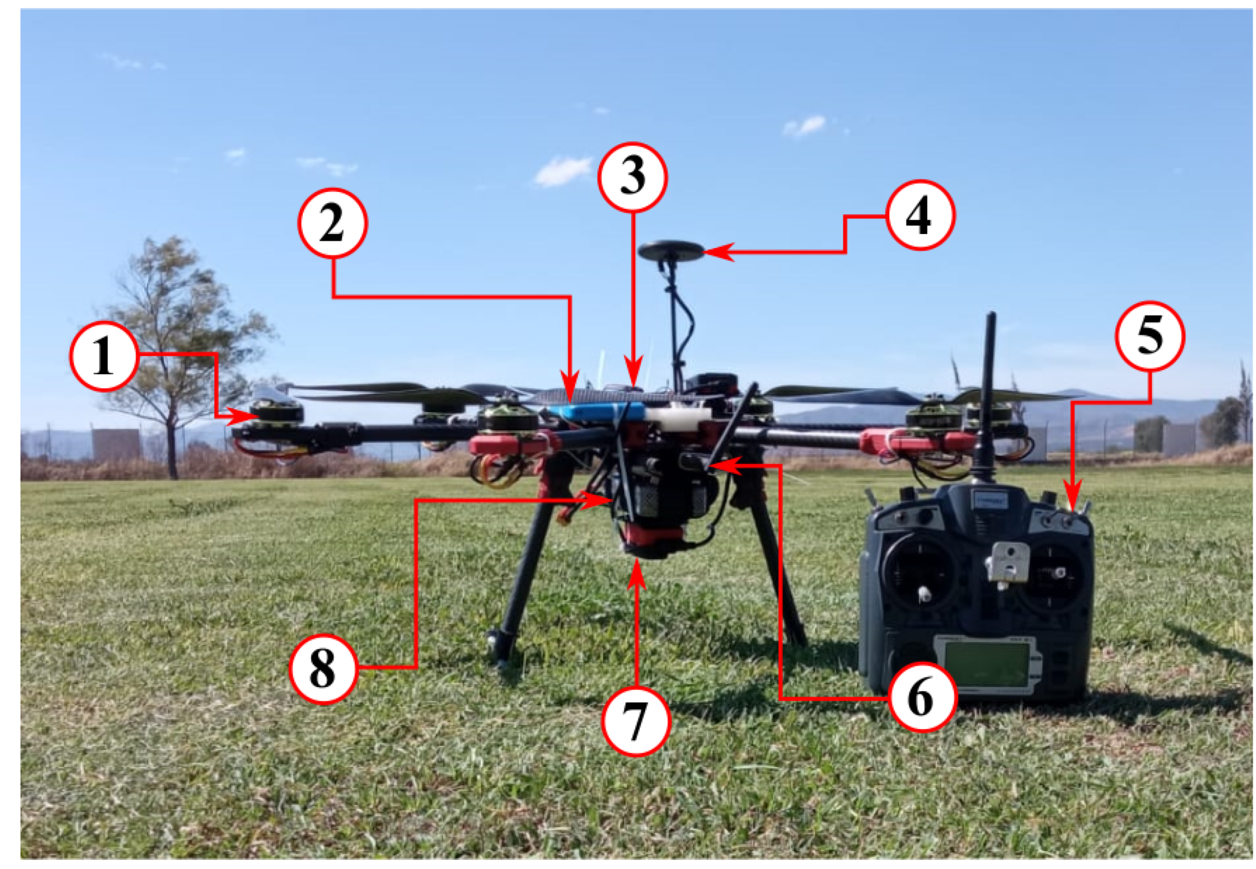
Figure 1. Hexacopter UAV platform with its main components: (1) brushless motor, (2) portable charger power bank, (3) flight controller, (4) GPS, (5) radio transmitter, (6) telemetry radio, (7) RGB and multispectral camera system, and (8) Li-Po battery.
Agriengineering 06 00161 g001
Figure 2. Scheme of the hexacopter UAV platform and image system.
Agriengineering 06 00161 g002
Figure 3. Hexacopter scheme illustrating the primary forces acting on the vehicle.
Agriengineering 06 00161 g003
Figure 4. Fault-tolerant control scheme used in a hexacopter UAV for agricultural flight planning.
Agriengineering 06 00161 g004
Figure 5. Three-dimensional position comparison of the faulty hexacopter with and without FTC.
Agriengineering 06 00161 g005
Figure 6. (a) Position, (b) Euler angles, and (c) yaw velocity of the faulty hexacopter utilizing FTC.
Agriengineering 06 00161 g006
Figure 7. Forces produced by the actuators under the proposed FTC scheme.
Agriengineering 06 00161 g007
Figure 8. In-flight image acquisition cameras: (a) SJ9000 to collect the RGB data and (b) Sequoia multispectral camera.
Agriengineering 06 00161 g008
Figure 9. (a) Angular field of view of a camera, (b) projection area and image dimensions.
Agriengineering 06 00161 g009
Figure 10. Area of interest and path waypoints with overlaps for the photogrammetric image.
Agriengineering 06 00161 g010
Figure 11. Diagram illustrating the Pix2Pix method for synthesizing NIR images from RGB images.
Agriengineering 06 00161 g011
Figure 12. Scenario 1—Hexacopter UAV performing flight trajectory and data collection.
Agriengineering 06 00161 g012
Figure 13. Scenario 1—Hexacopter flight planning: (a) from the software Mission Planner version 1.3.77, (b) showing the area of interest from Google Maps.
Agriengineering 06 00161 g013
Figure 14. Scenario 1—Orthomosaic: (a) showing the images captured with the hexacopter UAV, (b) generated by PIX4D mapper.
Agriengineering 06 00161 g014
Figure 15. Scenario 2—Example of an RGB–NIR pair used in the experiments: (a) RGB image, (b) NIR image.
Agriengineering 06 00161 g015
Figure 16. Scenario 2—Examples of estimated NIR using Pix2Pix method: (a) RGB images, (b) real NIR images, and (c) estimated NIR images.
Agriengineering 06 00161 g016
Figure 17. Scenario 2—NDVI generated with (a) a real NIR image, (b) an estimated NIR image.
Agriengineering 06 00161 g017
Figure 18. Scenario 2—Orthomosaic and NDVI generated with estimated NIR imagery applied to a sugarcane crop during its tillering stage.
Agriengineering 06 00161 g018
Table 1. Components of the hexacopter UAV platform.
ComponentSpecificationValue
MotorTurnigy multistar600 kv (×6)
PropellerCarbon fiber13 × 4 in (×6)
ESC controllerAfro ESC30 A (×6)
Power bankPortable charger10 Ah
BatteryLi-Po10 Ah 3 s 25 c
Radio controlTurnigy 9X2.4 GHz
Telemetry3DR915 MHz
FrameTarot 680 pro
Flight controllerPixhawk 2.4.8
GPSUblox Neo-M8N
RGB cameraSJ9000
Multispectral cameraParrot Sequoia
Table 2. Parameters of the the hexacopter UAV.
ParameterValueUnit
Mass of the vehicle, m s 2.95 Kg
Acceleration due to gravity, g 9.81 m/s2
Drag force coefficient, d f 0.3 Ns
Drag torque coefficient, d t 0.7 Nms
Moment of inertia about x, J x 0.064 Kgm2
Moment of inertia about y, J y 0.061 Kgm2
Moment of inertia about z, J z 0.312 Kgm2
Ratio between torque and lift, k u 0.2
Motor’s maximum thrust force, f m a x 10.12 N
Motor’s constant, w m 39
Table 3. Hexacopter UAV controllability analysis.
η ¯ = [ 1 , η 2 , 1 , 1 , 1 , 1 ]
Fault η 2 1 0.9 0.8 0.7 0.6 0.5 0.4 0.3 0.2 0.1 0
ACAI * 2.26 2.03 1.81 1.58 1.35 1.13 0.90 0.67 0.42 0.17 0
CY *CN *CNCNCNCNCNCNCNCNCNUCN *
ACAI-WY * 2.49
* ACAI: Available Control Authority Index, CY: Controllability, ACAI-WY: ACAI without yaw, CN: Controllable, UCN: Uncontrollable.
Table 4. Study parameters.
TypeParameter
IndependentUAV flight altitude
IndependentSensor type
IndependentActuator fault scenarios
DependentNDVI values
DependentUAV stability
DependentData accuracy
CropSugarcane
OtherTillering stage
Table 5. Similarity results of the images from Figure 16.
DataSSIMPSNR
Image 1 0.65 12.4 dB
Image 2 0.53 10.8 dB
Table 6. Meaning of NDVI values [42].
Type of ObjectsNDVI Value
High, dense vegetation0.1–0.7
Sparse vegetation0.5–0.2
Open soil0.2–0.025
Clouds0
Snow, ice, dust, rocks0.1–−0.1
Water−0.33–−0.42
Artificial materials−0.5
Disclaimer/Publisher’s Note: The statements, opinions and data contained in all publications are solely those of the individual author(s) and contributor(s) and not of MDPI and/or the editor(s). MDPI and/or the editor(s) disclaim responsibility for any injury to people or property resulting from any ideas, methods, instructions or products referred to in the content.