Abstract
A micro-tiller vibrates severely during the rotary tillage process, which may cause operators to develop white finger disease. However, for most vibration models, the acting force between the soil and the rotary cutter roll was simplified to only a constant or sine curve, which may not describe the whole dynamic. Rotary tillage processes have been simulated based on the smoothed particle hydrodynamics method in this paper. The acting forces of the soil on the cutter roll have been obtained with the simulation model. Four different working conditions were simulated. The average error between the calculated forces and the simulated mean forces is 10.96%, which proves the SPH model. By introducing simulated acting forces into the vibration model, a new vibration model of the micro-tiller, which includes the soil–blade interaction, has been constructed. Time and frequency characteristics were simulated with the new vibration model. The errors between the simulated and tested RMS values are 4.28%, 5.03%, and 6.35% for the engine, cutter roll, and right handle, respectively. Two domain-dominant frequencies were found with the vibration model, namely 44.7 Hz and 257.0 Hz. It is helpful to reveal the whole dynamic map of micro-tillers.
1. Introduction
A micro-tiller is a typical kind of primary tillage equipment. It is widely used in small and medium farms, especially in small hilly farms. It can be used for rotary tillage, fertilization, weeding, and other field management. However, the tiller vibrates severely during the tillage process. The vibration is transmitted to the operators, which may cause white finger disease. The mechanical structure of a micro-tiller is simple. However, the vibration of a micro-tiller is an interesting problem. There are two vibration sources for a micro-tiller, namely the engine and the interaction between the blade and the soil. On one hand, the forces acting on the blade when developing a vibration model are a typical problem for soil engagement implements. On the other hand, the vibration passed from the handle to the operator’s hand and arm is an ergonomics engineering dynamic question.
Some research has been conducted to find the reason for vibration transmission and vibration control measurements for micro-tillers. Yang et al. [1] developed a virtual micro-tiller prototype model to analyze the vibration mechanism. It shows that the handle’s first natural frequency is consistent with the rotating speed of the engine. And the handle’s vibration can be reduced effectively by adding an extra mass. Liu et al. [2] developed a rigid–flexible coupling dynamic model of a power tiller to study its vibration characteristics. The hand-transmitted vibration for a hand-tractor in actual field conditions was measured and analyzed. It emphasizes the need to provide interventions to reduce hand-transmitted vibration [3]. The interventions made of three different materials were designed to be placed at the interface of the handle bar and chassis to reduce vibration transmission between the surfaces. The test results show that with the help of the interventions, vibration is reduced, and the average exposure time for the occurrence of white finger syndrome increases [4]. To reduce the vibration transmitted from the engine to the frame, a mass-spring-damper model was constructed, and a set of vibration isolation devices was designed [5]. Sun et al. [6] invented a magnetorheological elastomer vibration isolator with variable stiffness and damping to isolate the vibration generated by the rotary tiller roll. Ko et al. [7] developed a kind of suspended handle to reduce the hand–arm vibration of a grass trimmer.
The interaction between the soil and blades is one of the main sources for vibration. The force acting on the cutter roll is vibrating and difficult to calculate precisely. However, most previous research considers the acting force of the soil on the cutter roll as a constant or trigonometric function. It cannot reflect all vibration characteristics. The cutting force acting on the tillage tool directly affects the power consumption of tillage implements and is key to the design of tillage implements. Simulation of the soil-cutting process mainly includes the discrete element method, finite element method, and smoothed particle hydrodynamics method (usually abbreviated to SPH).
The finite element method has been applied to predict soil stress distribution, soil deformation, soil failure positions, and tool uplift forces [8]. Mouazen et al. [9,10] obtained the forces, soil deformation, and normal pressure distribution on a subsoiler face with the finite element method. A good approximation of the maximum upward soil movement for the experiments was obtained. Jafari et al. [11] introduced a finite element model to simulate the bent-leg plow process. Davoudi et al. [12] built a two-dimensional nonlinear finite element model to simulate the behavior of a tillage tool moving in a bulk of soil. The soil failures and force reactions were discussed. Ibrahmi et al. [13] discussed the soil–blade orientation effect on tillage forces determined by a three-dimensional finite element model with Abaqus Explicit and linear forms of the Drucker–Pager model. It proves that the finite element method has made much progress in evaluating tool draft, stress and strain distribution position, and displacement and acceleration fields in soil–tool interactions, which help to design tillage tools [14]. However, the soil-cutting process is a large deformation problem. When it is used to simulate the soil-cutting process, there is mesh distortion, which leads to an increase in simulation error.
The discrete element method has been widely used to simulate soil and other agricultural material, for example, seeds and fertilizer. However, the accuracy of simulation is highly based on parameter calibration. Ucgul et al. [15] studied the influence of soil-cutting edge geometry on tillage forces with both the discrete element method and finite element method. It shows that the calibrated DEM is able to simulate tillage forces better than the FEM. Zhou et al. [16] have simulated and designed a Carrot Combine Harvester Ripping Shovel with the discrete element method. Cui et al. [17] simulated a drilling temperature rise in frozen soil in a lunar polar region with the discrete element method. The results reveals that the flow of lunar soil can effectively take away thermal energy. Sun et al. [18] optimized the rock-cutting process to reduce wear and energy consumption during the disc-cutter process. Zhang et al. [19] proposed a new modeling method for plow pan soil and simulated the tillage performance of a bionic subsoiler. Xianliang et al. [20] proposed a new soil parameter calibration method to simulate the tyre–soil interaction more precisely. Rui et al. [21] proposed a systematic method for calibrating the interaction parameters of sand particles with a combination of experiments and simulation. The contact parameters of particulate materials in a residual film mixture after sieving were also calibrated through physical tests and simulation tests [22].
The smoothed particle hydrodynamics method is a mesh-free method. It has unique advantages that other finite element methods and boundary element methods do not have in dealing with large deformation, and large displacement and distortion. It can be applied to deal with complex constitutive behaviors precisely [23]. The SPH method has been used to simulate a typical tillage process. Hu M et al. [24] built a soil–tool SPH model based on an elastoplastic constitutive with a shear failure model and a contact algorithm. Then, the cutting process and soil–tool interaction for both non-cohesive and cohesive soil were simulated. Major T. and Csanády V. [25] determined the horizontal force magnitude acting on a rotating tool under two different driving speeds with a FEM-SPH simulation method. Li S. et al. [26] simulated a rotary soil-cutting process with the SPH method and optimized the blade parameters to reduce power consumption.
To explore the micro-tiller’s whole dynamic, the interaction forces between the soil and rotary blades have to be considered. The SPH method was used to simulate the forces acting on the cutter roll. Then, a micro-tiller vibration model was built. And the whole dynamic characteristics of the micro-tiller were discussed and compared with the field test results.
2. Soil-Cutting Process Simulation with the SPH Method
2.1. Simulation Model
A three-dimensional solid model of the rotary cutter roll is shown in Figure 1. During the rotary tillage process, firstly, the tip of the blade pierces the surface of the soil and then the blade enters into the soil, which performs a rotary tillage movement. The back part of the blade pushes and breaks the soil. The broken soil particles fly out by inertia force, thereby further breaking the soil. It is difficult to calculate the forces of the soil acting on the whole cutter roll. Therefore, considering the properties of the soil, we built a simulation model based on the SPH method to calculate the acting forces of the soil on the cutter roll with LS-DYNA R7.1.0.
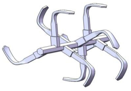
Figure 1.
Solid model of rotary cutter roll.
The material constitutive model in the LS-DYNA software material library modified the standard Mohr–Coulomb yield surface criterion, namely the “MAT147 MAT_FHWA_SOIL”. It has been proved to be effective to simulate soil. The modified Mohr–Coulomb yield surface criterion is shown as Equation (1):
where, is pressure; is the internal friction angle; is the function of the tensor plane angle; is the second invariant of the stress deviation tensor; is the cohesion coefficient; and is the corrected yield surface fitting coefficient.
The selected soil is yellow–brown soil distributed in the central region of China. The soil moisture content, density, shear modulus, specific particle gravity, and internal friction angle were tested with proper methods as listed in Table 1. Soil samples were obtained with a five-point sampling method in an experimental field in Henan Agricultural University. The soil moisture was tested with an electric oven as shown in Figure 2a. The soil shear modulus and internal friction angle were tested with direct shear apparatus, as shown in Figure 2b.

Table 1.
Simulation parameters of rotary cutter roll and soil.
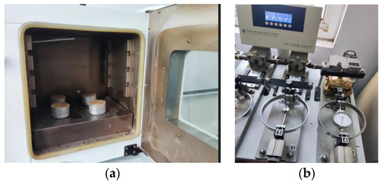
Figure 2.
Soil parameters tests. (a) Electric oven; (b) direct shear apparatus.
Based on the MAT147 MAT_FHWA_SOIL constitutive model, a soil model was built with a cube of 1 × 0.5 × 0.8 m3; 1 m is in the x direction, 0.5 m in the y direction, and 0.8 m in the z direction. There are a total of 204,800 soil particles. The specific material parameters of the soil particles and the cutter roll model are also all listed in Table 1.
2.2. Simulation Results
The soil particles on the border-left, border-right, and border-bottom are set as group 1 with “*Set Data_*SET_NODE” from the Entity Creation module. The other soil particles are set as group 2. The displacements of group 1 in all directions are constrained, which forms a fully constrained boundary of SPH particles to simulate deep hard soil and prevent other soil particles from flying away. The motion of the cutter roll has been decomposed into linear motion and circular motion; the linear velocity is set to 0.25 m/s, and the circular velocity is set to 4 r/s. The tillage width is 0.35 m, and the tillage depth is 0.1 m.
The contact mode is set to point-surface contact, which is the default contact form of the SPH method. The simulation time is set as 1 s. And the time interval between outputs is set as 0.002 s. The rotary tillage process model is shown in Figure 3.
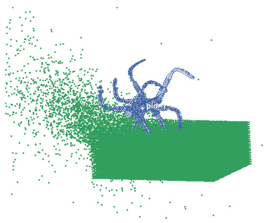
Figure 3.
Simulation model of rotary tillage process based on SPH method.
With the SPH method, the rotary tillage process has been simulated. The simulation results are shown in Figure 4. It can be seen that the soil particles have been stirred up by the rotary cutter roll. The soil fragmentation line is perfectly synchronized with the angle of the blade cutting into the soil.

Figure 4.
Simulated rotary tillage process based on SPH model.
The simulated forces of the soil on the cutter roll are shown in Figure 5. It can be seen that the simulated forces vibrate periodically. The acting force of the soil on the cutter roll can be calculated according to empirical Equation (2).
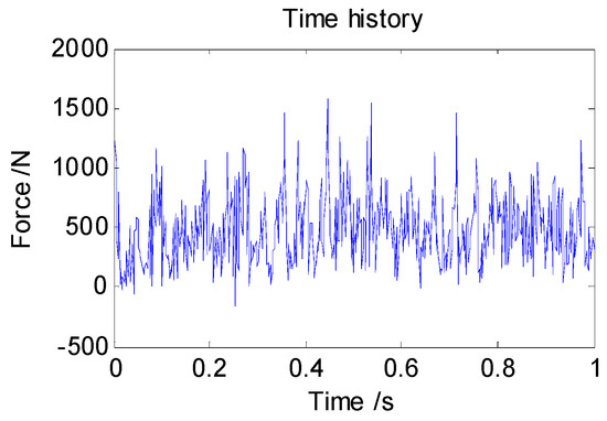
Figure 5.
Simulated vertical force of soil on cutter roll.
The acting force of the soil on the cutter roll can be calculated according to the following empirical Equation (2):
where is the torque; is the engine power; n is the engine rotary speed; is the cutting force; is the tool rotation radius; h is the tillage depth; and is the angle between the vertical plane and the straight line formed by the resultant force of the cutting force and the center of the cutter roll. To verify the simulation results, the forces acting on the cutter roll have been compared to the forces calculated with empirical formulas.
In Table 2, four operating conditions were listed with different cutter roll speeds and tillage depths. The simulated forces were compared to the forces calculated with empirical formulas. The errors are 11.87%, 12.86%,10.32%, and 8.77%, respectively, and the average error is 10.96%, which verifies the simulation model.

Table 2.
The simulated acting forces compared with the forces calculated with the empirical formula.
3. Vibration Model
The micro-tiller and its structure diagram are shown in Figure 6. The vibration model discussed in this paper is just as shown in Figure 7 and Equation (3) [27]. But the acting force of the soil on the cutter roll is different. The acting force is obtained from the simulation results from the SPH simulation model.
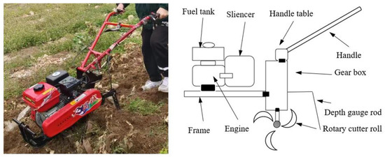
Figure 6.
The micro-tiller and its structure diagram.
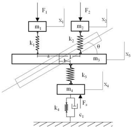
Figure 7.
The equivalent spring mass model.
4. Vibration Tests
4.1. Experimental Design
To explore the vibration characteristics of the micro-tiller, vibration tests in fields were conducted. The tests were carried out in the experimental fields of Henan Agricultural University. The micro-tiller vibration testing system is shown in Figure 8. Three acceleration sensors were fixed on the micro-tiller to test the vibration. One sensor was placed on the engine; the second one was fixed on the rolling bear of the cutter roll; and the third one was mounted on the right side of the handle. The signals were then collected by a multi-channel collector. Finally, the signals were analyzed with a vibration signal analysis system.
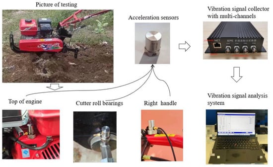
Figure 8.
The vibration testing system of the micro-tiller.
In order to reduce the influence of the soil and operators on the test results, the tests were carried out on in a field with relatively uniform soil density, moisture content, and soil firmness. And the tiller was operated by the same skilled operator. The tested micro-tiller had two gears, namely a slow gear and fast gear. In the slow gear, the cutter roll rotate speed is 2 r/s, and for the fast gear, it is 3 r/s. Two tests were conducted in the slow and fast gear, respectively. To ensure the reliability of the data, every test lasted for 9 s.
4.2. Test Results Analysis
The testing root mean square values for the main parts of the tiller, namely the RMS values, in the low- and high-speed gears are listed in Table 3. It can be seen that the RMS values in the high gear for the cutter roll, engine, and right handle are all bigger than those in the low gear. It indicates that the micro-tiller vibrates more severely in the high gear. For both the low gear and the high gear, the RMS values for the cutter roll and handle are bigger than that of the engine.

Table 3.
The tested RMS values.
To further explore the vibration characteristics of the micro-tiller, the time history and frequency domain under low and high gears have also been discussed. Take test 2, for example. The time history and frequency domain are shown in Figure 9. Some low frequencies exist in the cutter roll, namely 3.6 Hz and 7.2 Hz. We can also find the 3.6 Hz and 7.2 Hz frequencies in the dominant frequencies of the engine and the handle. The rotational speed of the cutter roll is 2 r/s. Therefore, the low frequencies are assumed to be related to the rotating speed of the cutter roll. The prominent frequencies for the engine are 44.9 Hz and 89.9 Hz. They are close to the first- and second-order inertial excitation forces of the engine. The domain frequencies for the handle are 3.6 Hz and 42.2 Hz, which are the most prominent frequencies of the cutter roll and engine. There are also some high frequencies in the frequency domain of the cutter roll, as commented in the figure, of 180 Hz and 347 Hz. It is assumed to be related to the inherent torsional or bending vibration frequency of the cutter roll.
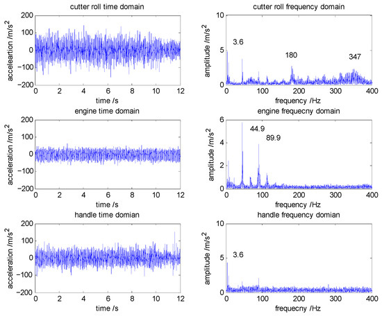
Figure 9.
Tested time history and frequency domain for the micro-tiller in the low gear.
Prominent frequencies and their amplitudes for all four tests are shown in Table 4. The tested time history and frequency domain for the micro-tiller in the fast gear is shown in Figure 10. When the micro-tiller runs in the high gear, the rotational speed of the cutter roll is 3 r/s, and the prominent frequencies for the cutter roll are 9.6 Hz for test 3 and 9.4 Hz for test 4. We can also find the 9.6 Hz frequency for test 3 and 9.4 Hz in the prominent frequencies of the engine and the handle. For all four tests, the engine vibrates at the first- and second-order of the inertial excitation forces of the engine. And the prominent frequencies of the handle are the prominent frequencies of the cutter roll and the engine. In addition, the amplitude of the high frequency, which is close to 347 Hz, becomes larger in the high gear compared to that in the low gear.

Table 4.
Tested prominent frequency and amplitude of the micro-tiller.
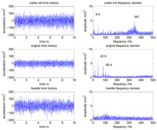
Figure 10.
Tested time history and frequency domain for the micro-tiller in the high gear.
5. Simulation and Discussion
The acting force obtained from the simulation model based on the SPH method has been coupled into the vibration model to construct a new micro-tiller vibration model. The simulation based on the SPH method is conducted in fixed steps. However, the iteration of the equations with ODE45 in MATLAB is in variable steps. The acting forces in variable steps are obtained with an interpolation method based on the fixed step simulation results with the finite element model.
For typical working conditions, when the forward speed is 0.25 m/s and the rotation speed of the cutter roller is 3 r/s, simulation analysis of the micro-tiller has been carried out. According to the simulation results, the RMS value of each part under the working condition has been settled and compared with the RMS values obtained from the test, as listed in Table 5. The errors between the tested RMS values and the simulated RMS values are 4.28%, 5.03%, and 6.35% for the engine, cutter roll, and right handle, respectively, which basically proves the effectiveness of the vibration simulation model of the micro-tiller. The simulated results show that the cutter roll and the handle vibrate more severely than the engine, which is the same as the tested results.

Table 5.
The simulated RMS values and tested RMS values.
The simulated time history and frequency of the main parts of the micro-tiller are shown in Figure 11. The frequency of the engine and the cutter roll is basically the same. There exist two relatively dominant frequencies, that is, 44.7 Hz and close to 257.0 Hz. The 44.7 Hz frequency is a first-order inertial excitation frequency, which is consistent with the results of the micro-tiller tests. Actually, the vibration characteristic of the cutter roll is very complex. Torsional vibration, bending vibration, and vertical vibration may be experienced by it. It is difficult to distinguish all the vibrations. The model built in this paper only considers the vertical vibration. So, the high frequency of 257 Hz is different from the tested high frequency of 347 Hz for many reasons. Though the model is not perfect, it provides a method to include soil–cutter roll interaction forces into the vibration model.
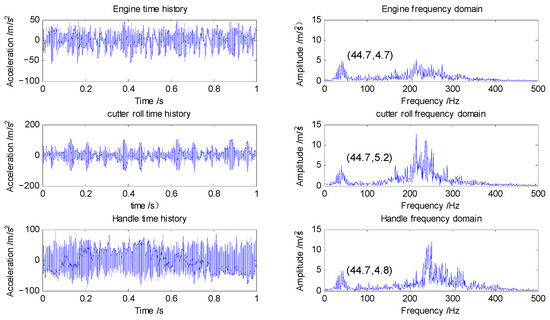
Figure 11.
Simulated time history and time domain of the main parts of the micro-tiller.
6. Conclusions
A simulation model for the rotary tillage process based on the SPH method was established in this paper. Four different working conditions with different depths and rotary speeds were simulated. The average error between the calculated forces and the simulated mean forces is 10.96%.
The simulated forces acting on the cutter roll were introduced into the micro-tiller vibration model. Therefore, a vibration model that includes the interaction between the soil and the cutter roll was built. The time and frequency characteristics were simulated with the new vibration model. The errors between the simulated RMS values and the tested RMS values are 4.28%, 5.03%, and 6.35% for the engine, cutter roll, and right handle, respectively. Two domain-dominant frequencies were found with the vibration model, namely 44.7 Hz and 257.0 Hz.
This paper has constructed a vibration model of a micro-tiller that includes the tillage process successfully. It helps to reveal the influence of the tillage process on the whole machine and study the whole dynamic of the micro-tiller. The method can be used to study the dynamic problems of other agricultural equipment with soil engagement components.
Author Contributions
Conceptualization, X.L.; methodology, X.L. and X.Z.; software, W.H. and X.L.; validation, Y.C. and Q.H.; writing—original draft preparation, X.L. and Z.S.; writing—review and editing, X.Z. and X.L. All authors have read and agreed to the published version of the manuscript.
Funding
This research was funded by the Science and technology project of Henan Province, grant number 232102111116; the Second-class Postdoctoral Research Grant in Henan Province grant number 202102061.
Data Availability Statement
The raw/processed data required to reproduce these findings cannot be shared at this time as the data also forms part of an ongoing study.
Conflicts of Interest
Author Qingle Hao was employed by the company “Ningbo Intelligent Machine Tool Research Institute Co. Ltd. of China National Machinery Institute Group”. Author Zhipeng Sun was employed by the company “Ningbo Songlan Cutting Tool Technology Co., Ltd.”. The remaining authors declare that the research was conducted in the absence of any commercial or financial relationships that could be construed as a potential conflict of interest.
References
- Yang, J.; Meng, X. Study on vibration mechanism and measures for vibration reducing to the handle of cultivator by virtual prototype technology. Nongye Jixie Xuebao Trans. Chin. Soc. Agric. Mach. 2005, 36, 39–42. [Google Scholar]
- Liu, Y. Analysis of vibration characteristics for power tillers based on a rigid-flexible coupling model. J. Vib. Shock. 2018, 37, 250–256. [Google Scholar]
- Dewangan, K.; Tewari, V. Characteristics of hand-transmitted vibration of a hand tractor used in three operational modes. Int. J. Ind. Ergon. 2009, 39, 239–245. [Google Scholar] [CrossRef]
- Chaturvedi, V.; Kumar, A.; Singh, J. Power tiller: Vibration magnitudes and intervention development for vibration reduction. Appl. Ergon. 2012, 43, 891–901. [Google Scholar] [CrossRef]
- Lu, S.; Xu, Z.; Jin, H.; He, M. Vibration Analysis and Vibration Damping Device Design of Power Tiller. IOP Conf. Series Mater. Sci. Eng. 2018, 452, 042180. [Google Scholar] [CrossRef]
- Sun, Y.; Ke, S.; Wang, G.; Liu, Z. Control Strategy Simulation Analysis of a New Micro-cultivator MR Elastomer Vibration Isolation System. Adv. Eng. Sci. Gongcheng Kexue Yu Jishu 2021, 53, 218. [Google Scholar]
- Ko, Y.H.; Ean, O.L.; Ripin, Z.M. The design and development of suspended handles for reducing hand-arm vibration in petrol driven grass trimmer. Int. J. Ind. Ergon. 2011, 41, 459–470. [Google Scholar] [CrossRef]
- Mouazen, A.; Neményi, M. A review of the finite element modelling techniques of soil tillage. Math. Comput. Simul. 1998, 48, 23–32. [Google Scholar] [CrossRef]
- Mouazen, A.M.; Neményi, M. Tillage Tool Design by the Finite Element Method: Part 1. Finite Element Modelling of Soil Plastic Behaviour. J. Agric. Eng. Res. 1999, 72, 37–51. [Google Scholar] [CrossRef]
- Mouazen, A.M.; Neményi, M.; Schwanghart, H.; Rempfer, M. Tillage Tool Design by the Finite Element Method: Part 2. Experimental Validation of the Finite Element Results with Soil Bin Test. J. Agric. Eng. Res. 1999, 72, 53–58. [Google Scholar] [CrossRef]
- Jafari, R.; Tavakoli, T.; Minaee, S.; Raoufat, M.H. Large deformation modeling in soil-tillage tool interaction using advanced 3D nonlinear finite element approach. In Proceedings of the 6th WSEAS International Conference on Simulation, Modelling and Optimization, Lisbon, Portugal, 22–24 September 2006; p. 6. [Google Scholar]
- Davoudi, S.; Alimardani, R.; Keyhani, A.; Atarnejad, R. A two dimensional finite element analysis of a plane tillage tool in soil using a non-linear elasto-plastic model. Am. Eurasian J. Agric. Environ. Sci 2008, 3, 498–505. [Google Scholar]
- Ibrahmi, A.; Bentaher, H.; Maalej, A. Soil-blade orientation effect on tillage forces determined by 3D finite element models. Span. J. Agric. Res. 2014, 12, 941–951. [Google Scholar] [CrossRef]
- Liu, X.H.; Yu, Y.; Qiu, L.C. An Overview of the Finite Element Method on the Tool-Soil Interacting Problem of Tillage. Appl. Mech. Mater. 2015, 707, 397–400. [Google Scholar] [CrossRef]
- Ucgul, M.; Saunders, C.; Fielke, J.M. Comparison of the discrete element and finite element methods to model the interaction of soil and tool cutting edge. Biosyst. Eng. 2018, 169, 199–208. [Google Scholar] [CrossRef]
- Zhou, W.; Ni, X.; Song, K.; Wen, N.; Wang, J.; Fu, Q.; Na, M.; Tang, H.; Wang, Q. Bionic Optimization Design and Discrete Element Experimental Design of Carrot Combine Harvester Ripping Shovel. Processes 2023, 11, 1526. [Google Scholar] [CrossRef]
- Cui, J.; Kui, L.; Zhang, W.; Zhao, D.; Chang, J. Simulation of Drilling Temperature Rise in Frozen Soil of Lunar Polar Region Based on Discrete Element Theory. Aerospace 2023, 10, 368. [Google Scholar] [CrossRef]
- Sun, Y.; Guo, C.; Li, Q.; Yue, H.; Zhang, J.; Wang, C.; Hu, Z.; Bo, T. Optimization of rock cutting process parameters with disc cutter for wear and cutting energy reduction based on the discrete element method. J. Clean. Prod. 2023, 391, 136160. [Google Scholar] [CrossRef]
- Zhang, L.; Zhai, Y.; Chen, J.; Zhang, Z.; Huang, S. Optimization design and performance study of a subsoiler underlying the tea garden subsoiling mechanism based on bionics and EDEM. Soil Tillage Res. 2022, 220, 105375. [Google Scholar] [CrossRef]
- Wang, X.; Hu, H.; Wang, Q.; Li, H.; He, J.; Chen, W. Calibration method of soil contact characteristic parameters based on DEM theory. Nongye Jixie Xuebao Trans. Chin. Soc. Agric. Mach. 2017, 48, 78–85. [Google Scholar]
- Rui, Z.; Han, D.; Ji, Q.; He, Y.; Li, J. Calibration methods of sandy soil parameters in simulation of discrete element method. Nongye Jixie Xuebao Trans. Chin. Soc. Agric. Mach. 2017, 48, 49–56. [Google Scholar]
- Zhou, P.; Li, Y.; Liang, R.; Zhang, B.; Kan, Z. Calibration of Contact Parameters for Particulate Materials in Residual Film Mixture after Sieving Based on EDEM. Agriculture 2023, 13, 959. [Google Scholar] [CrossRef]
- Liu, M.B.; Liu, G.R. Smoothed Particle Hydrodynamics (SPH): An Overview and Recent Developments. Arch. Comput. Methods Eng. 2010, 17, 25–76. [Google Scholar] [CrossRef]
- Hu, M.; Gao, T.; Dong, X.; Tan, Q.; Yi, C.; Wu, F.; Bao, A. Simulation of soil-tool interaction using smoothed particle hydrodynamics (SPH). Soil Tillage Res. 2023, 229, 105671. [Google Scholar] [CrossRef]
- Major, T.; Csanády, V. Combined FEM-SPH Simulation Method for the Modeling of the Interaction of Tillage Tools and the Soil. Erdészettudományi Közlemények 2015, 5, 7–19. [Google Scholar] [CrossRef][Green Version]
- Li, S.; Chen, X.; Chen, W.; Zhu, S.; Li, Y.; Yang, L.; Xie, S.; Yang, M. Soil-cutting simulation and parameter optimization of handheld tiller’s rotary blade by Smoothed Particle Hydrodynamics modelling and Taguchi method. J. Clean. Prod. 2018, 179, 55–62. [Google Scholar] [CrossRef]
- Liu, X.; Wang, Y.; Zhang, X.; Tian, H.; Yu, F. Handheld Micro tiller time-frequency characteristic and vibration isolation measures. J. Vibroeng. 2022, 24, 824–835. [Google Scholar] [CrossRef]
Disclaimer/Publisher’s Note: The statements, opinions and data contained in all publications are solely those of the individual author(s) and contributor(s) and not of MDPI and/or the editor(s). MDPI and/or the editor(s) disclaim responsibility for any injury to people or property resulting from any ideas, methods, instructions or products referred to in the content. |
© 2024 by the authors. Licensee MDPI, Basel, Switzerland. This article is an open access article distributed under the terms and conditions of the Creative Commons Attribution (CC BY) license (https://creativecommons.org/licenses/by/4.0/).