Article

Traction Force, Sowing Quality, and Deformation Characteristics of the Coulter of a Grain–Fertilizer–Grass Seeder

by
Sayakhat Nukeshev
1,
Dinara Kossatbekova
2,*,
Mikalai Ramaniuk
3,
Almat Sagitov
2,
Yerzhan Akhmetov
1,
Indira Mamyrbayeva
1,
Khozhakeldi Tanbayev
4,* and
Kaldybek Tleumbetov
1
1
Department of Technical Mechanics, NCJSC Saken Seifullin Kazakh AgroTechnical Research University, Astana 010011, Kazakhstan
2
Department of Technological Machines and Equipment, NCJSC Saken Seifullin Kazakh AgroTechnical Research University, Astana 010011, Kazakhstan
3
Department of Mechanics of Materials and Machine Parts, Belarus State Agrarian Technical University, 220012 Minsk, Belarus
4
Department of Engineering Technologies and Transport, Shokan Ualikhanov Kokshetau University, Kokshetau 020000, Kazakhstan
*
Authors to whom correspondence should be addressed.
AgriEngineering 2024, 6(3), 2326-2351; https://doi.org/10.3390/agriengineering6030136
Submission received: 15 June 2024 / Revised: 15 July 2024 / Accepted: 16 July 2024 / Published: 19 July 2024

Abstract

:
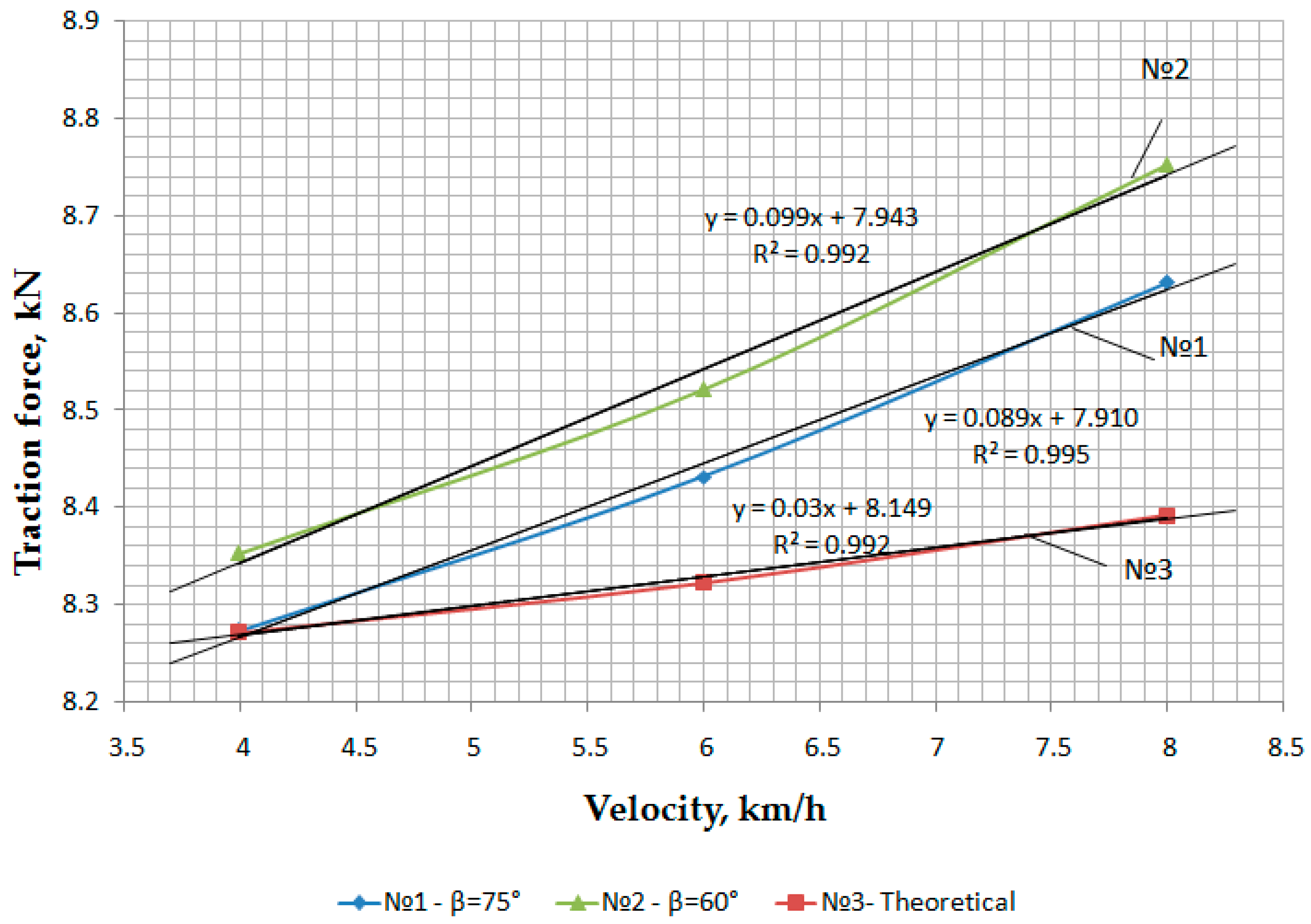
The development of restoration technology and meadows, improvement of run-down pastures, and productivity improvement of old crops of perennial grasses is an urgent problem in agriculture. The tillage traction force in seeder designing and manufacturing is an important indicator of energy efficiency. The objective of this work is to reduce traction force and ensure seeding depth uniformity by justifying the optimal chisel parameters of a grain–fertilizer–grass seeder for direct seeding in sod. The Box–Behnken method was applied to investigate the traction force dependence on the seeder velocity, seed embedding depth, chisel width, and mounting angle. The obtained optimal parameters of coulters were justified by the finite element method. Structural and technological parameters were checked using the smoothed-particle hydrodynamics method on the deformation and wear of the seeder working body. The revealed optimal coulter parameters were as follows: chisel width was 20–20.97 mm, chisel length was 145–148.9 mm, mounting angle was 75°–81.6°, and achieved minimum traction force was 720 N. These parameters ensure the quality of grass seed embedding in the sod. The theoretical data of traction force (8.27–8.39 kN) are in accordance with the experimental (8.28–8.63 kN) data under field conditions. These findings are efficient in agrotechnical and mechanical predictions regarding the occurrence of chisel residual stresses and the working lifetime of the part.

1. Introduction

Increasing the productivity [1,2] of meadows and pastures, restoring run-down pastures, and planting old-age crops of perennial grasses in arid zones where soil with hard physical and mechanical properties requires implementation of adapted universal technical means. New technical means [3,4], although effective in climate-changing problems, cause the expansion of arid regions, leading to risky farming. During the design and manufacturing processes of the seeder, the traction force for tillage is an important indicator of energy efficiency, resulting from the stress–strain [5,6] interaction of the tractor wheels with the topsoil [7]. At the design and calculation stages, technical decisions to minimize the traction resistance of an agricultural machine have to be accepted, and they depend on the structure, materials, and other design features. Justifying the interaction of various factors and identifying each component of them is the basis for evaluating, calculating [8,9], and predicting traction resistance.
Existing seeders for direct seeding into sod do not fully provide the technological process in conditions of arid zones, where the soil cover has a complex, compacted crust of the upper horizon. Using chisel coulters for fertilizer application during spring crops, causes more significant soil mobilization, considering that fertilizer application at greater depths can stimulate root burial. The chisel coulter requires a traction force for furrowing from 2.0 to 3.8 kN, depending on the furrow depth, the chisel’s geometry and angle, the pointer with the soil, and the soil moisture [10]. Moreover, the use of chisel-shaped working bodies in arid zones requires the application of tractors with higher traction force in narrow working speed ranges [11]. Any deviation from the optimal operating speed can deteriorate significantly the quality of work and lead to increased energy consumption [12,13]. Furthermore, using chisels increases traction requirements and fuel consumption, reducing tractor/seeder speeds compared to the same number of rows [14]. Evaluating the exploitation parameters of the mechanized complex of rod and double-disk coulters on oxidized soil, a study [15] found that compared to the double-disk coulter, the anchor coulter increased the average traction force by 32%. Notably, in studies conducted in Rhodic Hapludox using a seeder consisting of four furrows and a coulter with a chisel, some studies [15,16] obtained traction force values of 10.20 and 10.17 kN. As a function of furrow depth, the average traction force has a linear relationship with increasing soil density. Soil compaction affects the traction force, and 23% more force is required to achieve the same furrow depth when comparing the highest and lowest soil density levels.
The discrete element models (DEMs) were developed in [17,18,19] and validated to evaluate the effects of key installation parameters of the subsoiler’s wing, such as the upward angle φ, the mounting height h, and the mounting angle β on soil-loosening efficiency η and soil-disturbance area ratio κ. Reducing the wing mounting height of subsoilers led to larger soil disturbance areas, decreased soil bulk density, improved crop performance, and moisture of the soil [20]. Increasing the mounting angle can increase the soil loosening efficiency of bending subsoiling tools without tractive force [21]. The results showed that φ had the most significant impact on η, followed by h and β. The significance of the effect of the implement parameters on κ was as follows: h, φ, and β. The impact of the interaction of φ and h on κ was also significant. The traction and vertical forces of the working body varied linearly and nonlinearly with the tilt angle. The traction force increased significantly as the inclination angle decreased. By optimizing the parameters of the working body, horizontal and vertical forces increased the soil-loosening and -lifting areas [22]; however, the specific settlement, soil bulk density, and resistance to penetration decreased. Three coulters with straight shanks, 90° (blunt and beveled), and 53° mounting angles were compared with two curved knife geometries (45 and 95 mm offset) on dry silty loamy field soil [23,24,25,26,27,28]. The 53° straight coulter showed the most incredible speed response, reducing furrow backfill and increasing lateral soil spread (from the center of the furrow). The addition of a double-sided chamfer reduced lateral soil spread and provided backfill at 8 km/h, but soil spread increased at 12 and 16 km/h. However, a coulter with a curved shank with a 45 mm offset had more significant soil spread at speed. It resulted in reduced furrow filling and increased lateral soil spread at 16 km/h (similar to straight shank coulters). In [28], it was found that furrow size was more dependent on the lateral displacement of the stem and the bending angle of the lateral stem than on the forward tilt angle of the lateral stem (>90°). The results show the potential of the new coulter technology to increase forward seeding speed by minimizing soil spread and traction, consequently improving seeding quality and seeder productivity. Narrow coulters are widely used for in-furrow seed embedment and fertilizer in pre-sowing; however, excessive soil mixing often limits their effectiveness.
The effect of coulter angle (35–90°) was modeled in [17,21] using DEM and was compared with previous studies to predict furrow profile parameters, such as loosening area, ridge height, depression area, furrow backfill, and lateral soil ejection. There was predicted to be a twofold decrease in thrust with increasing the mounting angle and a changing in vertical force at 71°, which is entirely in line with trends. In studies [22,26,29,30,31,32], the discrete element method was applied to model the soil and moldboard plow interaction associated with soil movement and tillage forces. The traction forces predicted using DEM were similar in magnitude to those calculated for different soil types. An increase in tillage depth led to rising traction force.
It is difficult or impossible to experimentally investigate the soil condition when the working bodies act on it. Therefore, many researchers [33] have used finite element method (FEM) modeling of the physical behavior of soil during its compaction to study the forces acting on tools, stress distribution in the soil, and the nature of soil failure. However, in some cases, traditional finite element or other grid-based discretization methods are not possible.
According to the results of the literature analysis revealed that, in the theoretical investigations that were applied, the Box–Behnken method to optimize the parameters, and also modeling using the FEM and DEM methods, could be used to substantiate the obtained parameters of the studied working bodies. Theoretical studies were also confirmed with laboratory studies in soil bins, and experimental studies in field conditions.
Field tests of a mock-up sample of a grain–fertilizer–grass seeder [34,35] showed that during direct sowing of grass seeds into the sod to a depth of 3 … 4 mm in several working organs, a chisel with a sharpened front edge with an angle of 60°, when cutting a slot in the soil, lifts and pushes aside the cut withered soil crusts. Thus, in some places, sod swelling after the pass reached 3–6 cm, with the depth of the chisel stroke of 6–8 cm. A wide, uncovered furrow was left in the coulter trace. It became necessary to theoretically justify the geometrical parameters and angles of chisel installation to exclude these consequences. The drawbacks suggest changes in the coulter design regarding the chisel parameters after their theoretical specification.
The purpose of this work is to reduce the traction force and ensure a uniformity in seeding depth by justifying the optimal parameters of the coulter chisel of a grain–fertilizer–grass seeder for direct seeding in sod. Accordingly, the factors influencing the quality of direct sowing under cover crops and in turf are determined, the constructive-technological scheme of coulter is substantiated, the occurrence of deformations and surface wear of the working body of the seeder is evaluated, and Lagrangian meshless methods of smooth particle hydrodynamics for soil media in modeling of soil fracture processes at high pressures is used. In accordance with the above listed factors, several laboratory experimental studies and field tests have been conducted.

2. Materials and Methods

2.1. Theoretical Study of the Traction Force

The equilibrium of external forces acting on it in the directions of horizontal and vertical axes is considered [34] to determine the coulter traction force, as follows:
P = 2 b h σ c s i n θ A 1 + B 1 + ϑ 2 h · ρ · b 2 · 4 s i n β · c o s α + φ A 2 B 2 ,
where: A 1 = s i n θ + φ 1 ,   A 2 = s i n α + φ 1 ,   B 1 = c o s θ + φ 1 · s i n α + φ c o s α + φ 1 , B 2 = c o s α + φ 1 · t g α + φ ,   α —nose angle of the working body,   φ —soil internal friction angle,   θ soil shear angle, β —chisel mounting angle, 2 b width of the working body, h —depth of travel of the working body, ϑ translational speed (velocity) of the working body ,   σ c —limiting resistance of the soil to compression, ρ soil volumetric weight. The traction force of the working body is equal to 720 N.
It can be seen from Equation (1) that the first term of the coulter traction force—resistances averaged from the parameters of the cultivated soil layer and its physical and mechanical characteristics, such as shear strain angle and ultimate resistance to compression—and the second term is inertial resistances to the movement of soil elements, depending on the translational speed of the working body and its mounting, nose, and friction angles.

2.2. Traction Force Determination under Laboratory Conditions

In laboratory experiments, a soil bin was used to determine the traction force of the experimental coulter (Figure 1). The technical characteristics of the soil bin is given in Table 1.
Figure 1 shows the general view of the laboratory soil bin. The soil bin has a measuring information system and an electronic dynamometer DEP3-1D-10R-2, with data registration on a PC, for the 2nd class, the maximum permissible relative compliance error is ±0.45%.

2.3. Design of Experiment Using the Box–Behnken Method

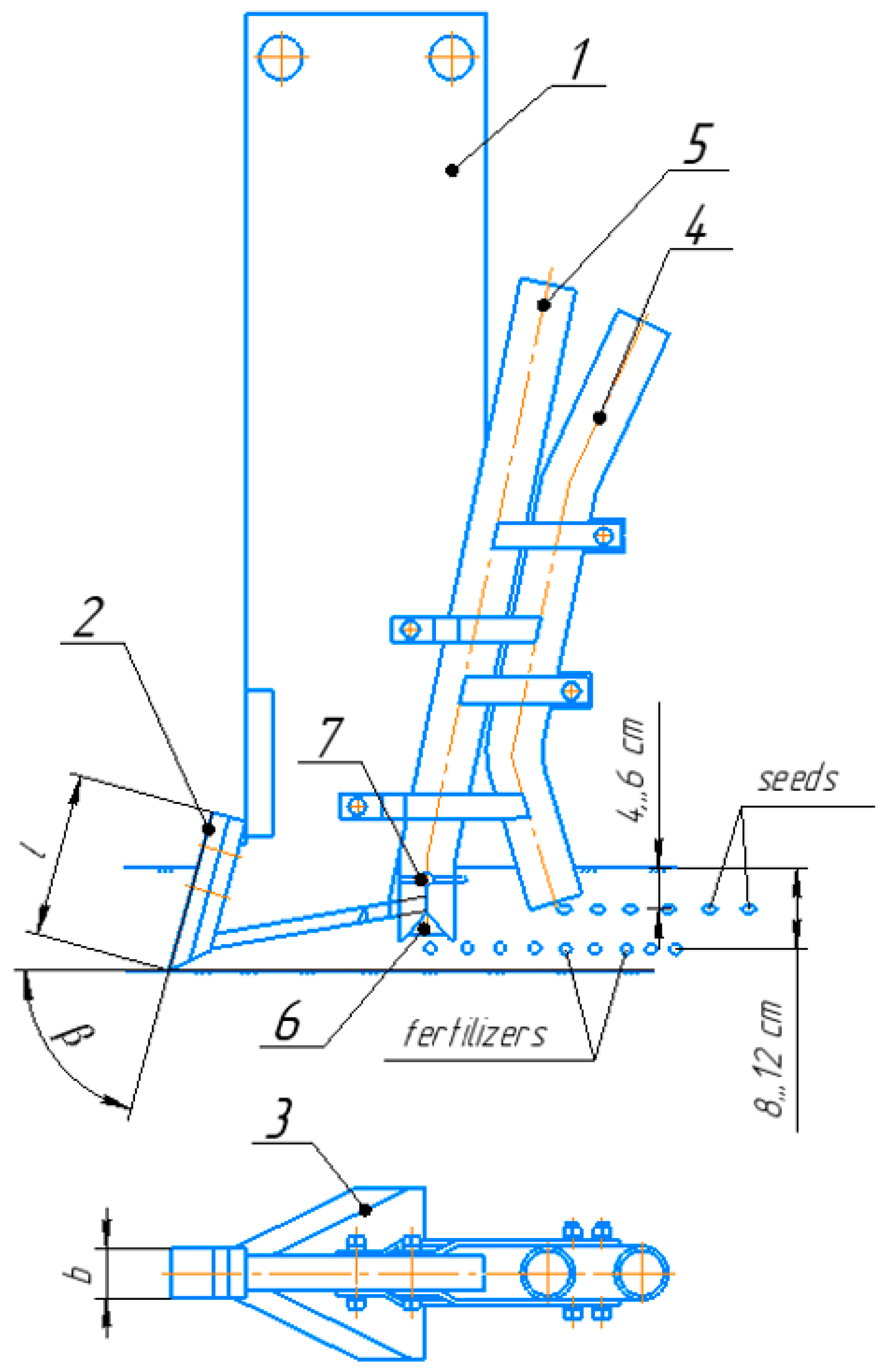
The experiments were carried out using the central composite rotatable second-order planning program [36] using the Box–Behnken [37] method to investigate the dependencies of traction force and non-uniformity of seed embedment depth on the parameters of the grain–fertilizer–grass seeder coulter chisel, and a polynomial of the second degree describing the optimum region was obtained. The following parameters were considered as influencing factors: width b and length l of the coulter chisel, and the mounting angle of the rear part to the horizon β (Figure 2).
The factor’s values and desirability functions were determined using Design of Experiments (DOE) [38] in the Statistica 10 program. Dependence graphs and the most optimal factors values were obtained using the Box–Behnken method. In statistics, the Box- Behnken method is experimental for the surface response methodology.
Planning the experiment according to the Box–Behnken method:
  • The levels of factors variation should be selected.
  • Encode the factors values −1, 0, and +1.
  • Use a planning matrix.
  • Calculate the regression coefficient.
  • Perform statistical analysis of the obtained model.

2.4. Traction Force Determinations in the Field

Field tests of hardened samples of the coulter chisels were conducted on ordinary chernozem in the Akmola region of Kazakhstan at sowing of vetch (spring), creeping clover, and alfalfa. The machine-tractor unit consisted of a wheeled tractor with traction class 2 and seeder [34,35].
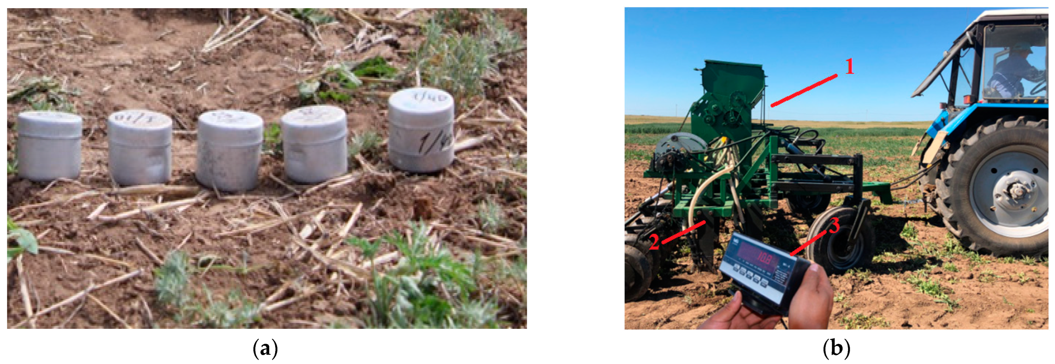
Before conducting field experiments, soil moisture and density were determined. Soil moisture was determined by taking soil samples of field moisture and productive moisture in aluminum bouquets using layer horizons in four places located along the diagonal of the plot at 5 cm depth intervals of 0–5, 5–10, and 10–15 cm, respectively, in threefold repetition (Figure 3a).
Soil hardness was determined using a Wile Soil penetrometer with a measurement range from 0 to 3500 kN/m2.
An electronic dynamometer model DEP1-1D-50P-2 (Figure 3b) was used to determine the traction resistance of the experimental coulter under study.

2.5. Determination of the Unevenness of Seed Embedment Depths

The regularity of seed embedment depth is one of the most important indicators of sowing quality and is expressed by the coefficient of variation νd. According to agrotechnical requirements, the deviation of 80% seed depth should not exceed ±1 cm, and no uncultivated seeds should be on the field’s surface.
For this study, the direct finding method (manual excavation) of seeds in the row was used. Seeding units with experimental working bodies were determined for each row of working bodies (front and rear) on two strips in two adjacent passes of the planter of one experiment. An indicator of the grain embedding depth is the distance from the grain to the cutting place, and more precisely, with the help of a measuring ruler, the distance from the top point of the underground part to the grain center is measured with an accuracy of 1 mm.

2.6. Modeling of Chisel Parameters Using the Finite Element and SPH Methods

The data obtained at experiment planning were analyzed and justified through the computer modeling in ANSYS LS-DYNA (Suite RS14 Student) using the finite element method (FEM) and Smooth Particle Hydrodynamics (SPH) methods. A three-dimensional model of the chisel was developed using the finite element method to study the experimental coulter behavior. The meshless (Lagrangian) Smoothed Particle Hydrodynamics (SPH) method was applied to provide an improved solution for solid–liquid parts on a free surface. In SPH modeling, the element under study interacts with particles, wall boundaries, and forces according to Newton’s second law.
Modeling in ANSYS [39] was performed to analyze the unitary stress distribution [3] on a 20 mm wide chisel. The following optimal parameters, according to SOLIDWORKS modeling results, were taken as design dimensions to study the chisel characteristic: width 20 mm, length 145 mm, angle of mounting 75°, and material steel 65 Mn. Chisel movement occurs along the OX axis, and the OZ axis determines the mounting angle of the working part in relation to the field surface. Modeling is carried out for dark chestnut soils (Table 2).
The most important among the input data for computer modeling are the mechanical properties of the material being machined. These properties are described using the finite element method (FEM) and the well-known Johnson–Cook model (Table 3 and Table 4).
The criterion of accumulated plastic deformations in the Johnson–Cook form is adopted as a physical criterion of fracture of a plastic deformable material [39]:
ω = ε ¯ ε f ¯ 1
where ε ¯ increment of the resultant plastic deformation; and ε f resultant material fracture strain.

3. Results

3.1. Theoretical Study of the Dependence of Coulter Traction Force on Structural and Technological Parameters

Based on the analysis (1), the graphs of traction force dependence (Figure 4, Figure 5, Figure 6, Figure 7 and Figure 8) on chisel mounting angle, working body width, embedding depth, and velocity by the formula (1) were obtained using the MathCAD 14 program (parameter settings of the calculation were as follows: strict singularity check, exact equality, and 0/0 = 0)
The change in traction force depending on the travel speed has a parabolic character (Figure 4a,b). When the seeder working speed increases, the value of traction force on the working body rises; however, when the values of the mounting angle are increased, they decrease.
It is explained by the fact that at the initial moment of tool–soil interaction, inertial forces arise because, at that moment, the inertia of the soil rest is broken, and its particles acquire certain accelerations and some absolute speed, which does not coincide with the slope line. Obviously, the inertial force will be directed along the line of absolute particle velocity only in the opposite direction. In the steady-state process of soil destruction, the traction force is minimal. However, the traction force also increases with further translational speed.
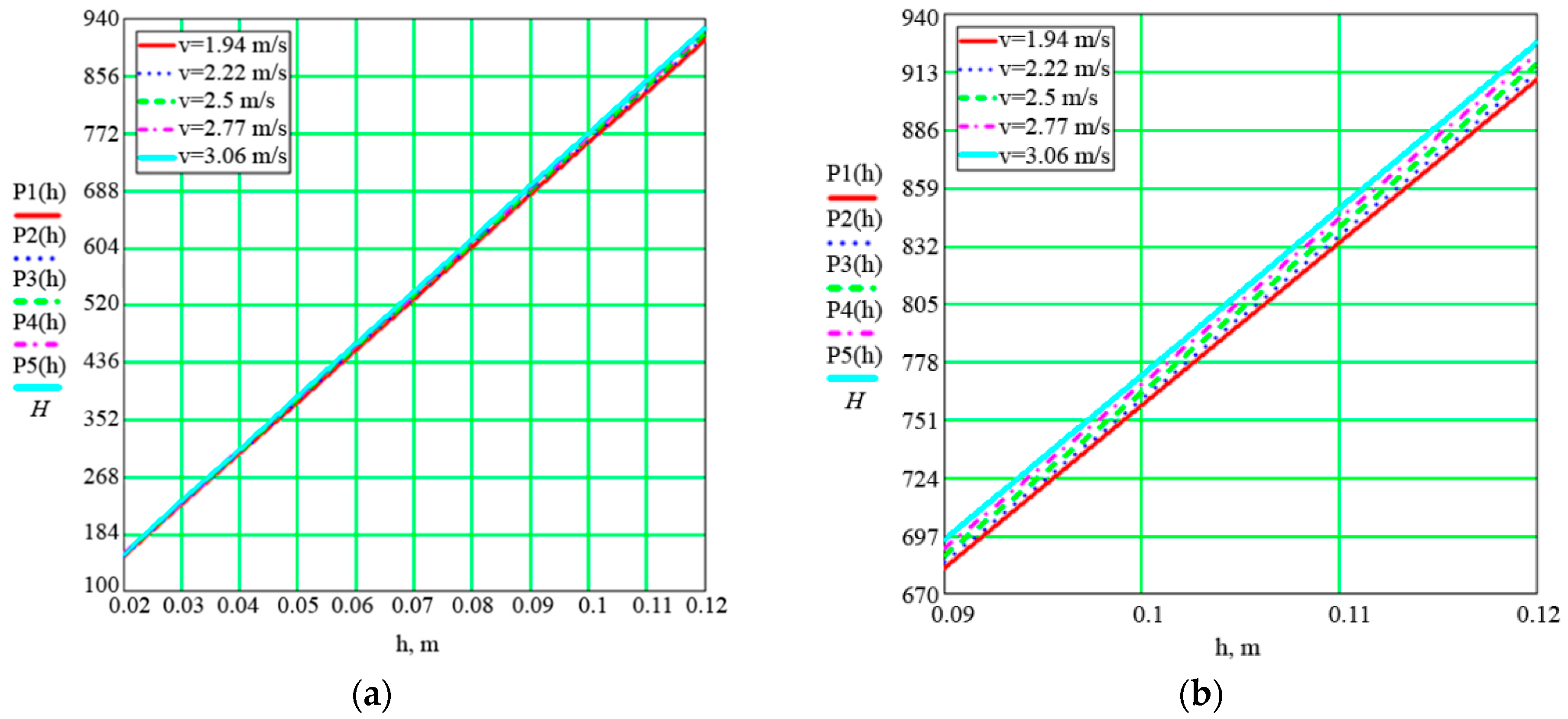
As shown in Figure 5, the value of traction resistance increases with each seed embedment depth. At a speed of 1.94 m/s, if the seeder is operated with a seed embedment depth of 0.1 m, the required tractive force will be approximately 760 N. An analysis of the graph presented in Figure 5 concludes that the set seeding depth significantly affects the traction resistance of the coulter and seeder, and has a directly proportional quadratic dependence.
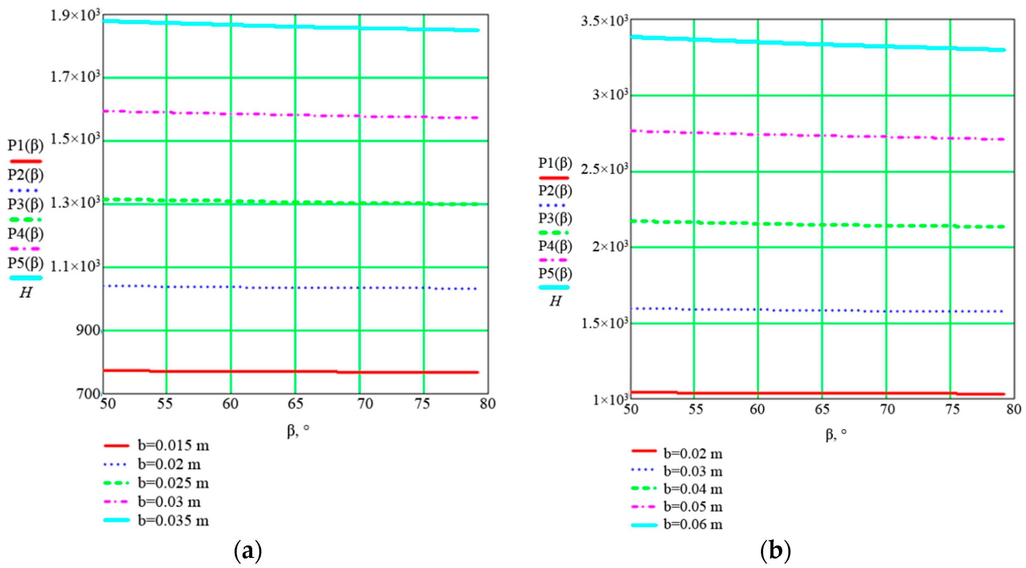
The traction force linearly depends on the mounting angle at different widths (Figure 6a,b). At width ranges of 0.015 ÷ 0.025 m, the traction force remains stable regardless of the mounting angle change. An imperceptible decrease in tractive force can be noted at width ranges of 0.03 ÷ 0.06 m by increasing the mounting angle up to 75–80 degrees. According to the graph (Figure 6), as the mounting angle increases, the traction force on the working remains stable due to the reduction in the length of the chisel working surface.
With an increase in the embedment depth, the value of the traction force on the working body increases significantly, and when the chisel width increases by 5 mm (0.005 m), the value of traction force increases by approximately 300 N (Figure 7).
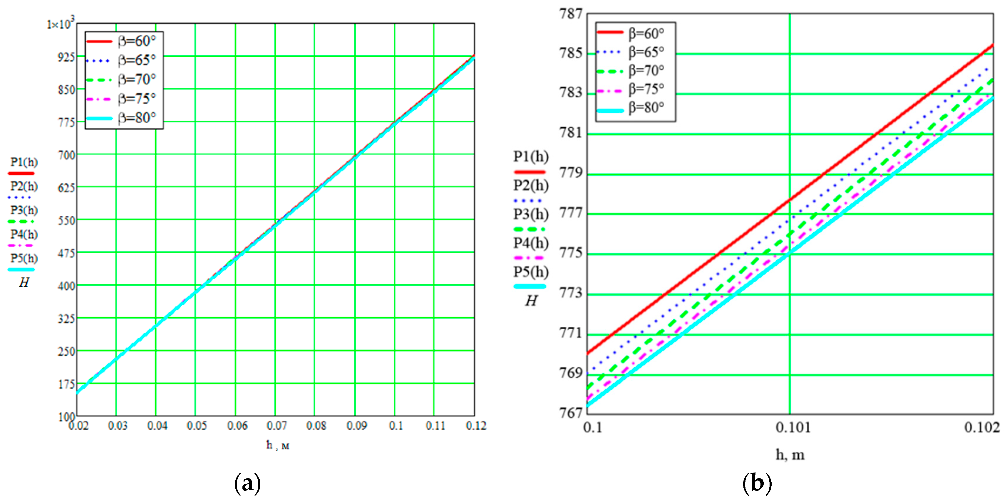
Analysis of the traction force dependence on the seed embedment depth at different mounting angles (Figure 8) shows that with increasing embedment depth, the value of traction force on the working body increases, but with increasing values of the mounting angle, it is almost not significant, especially at β = 70° ÷ 85° in comparison with β = 60°.
From the obtained graphs of dependencies from the Formula (1), it can be concluded that the increase in chisel width, seed embedment depth, and velocity leads to a rise in the value of traction force. Another interesting point is that the opposite situation occurs when increasing the mounting angle—the traction force decreases.

3.2. Selection of Optimal Structural and Technological Parameters of the Coulter

The experiment was carried out using Box–Behnken methods to determine the dependences of traction force P and unevenness of seed embedment depth νd (wheatgrass and turfgrass) on the design parameters of the coulter of the grain–fertilizer–grass seeder. The dependencies P = f (b, β, l) and νd = f (b, β, l) were solved to be approximated by a polynomial of the second degree [40]. The levels and intervals of variation of the factors adopted in the study are given in Appendix A (Table A1).
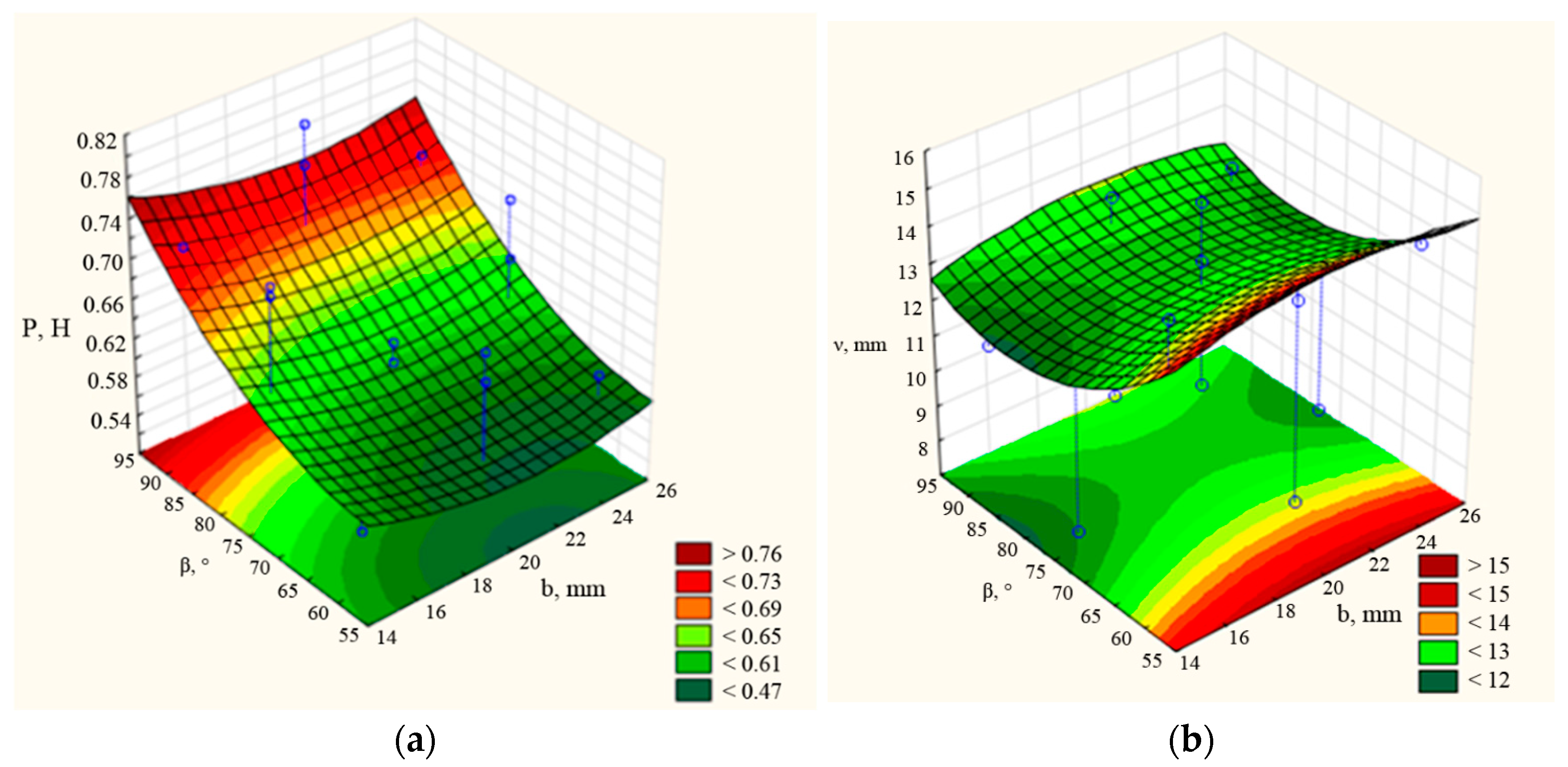
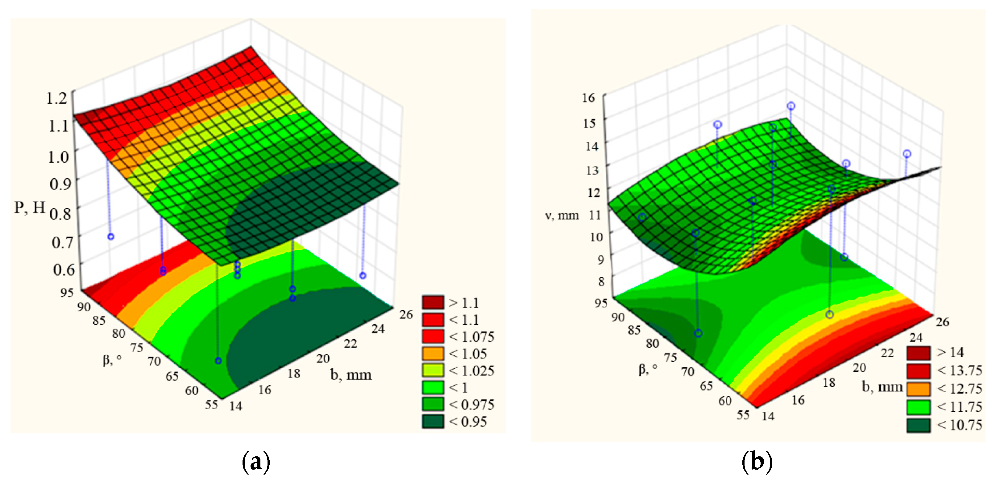
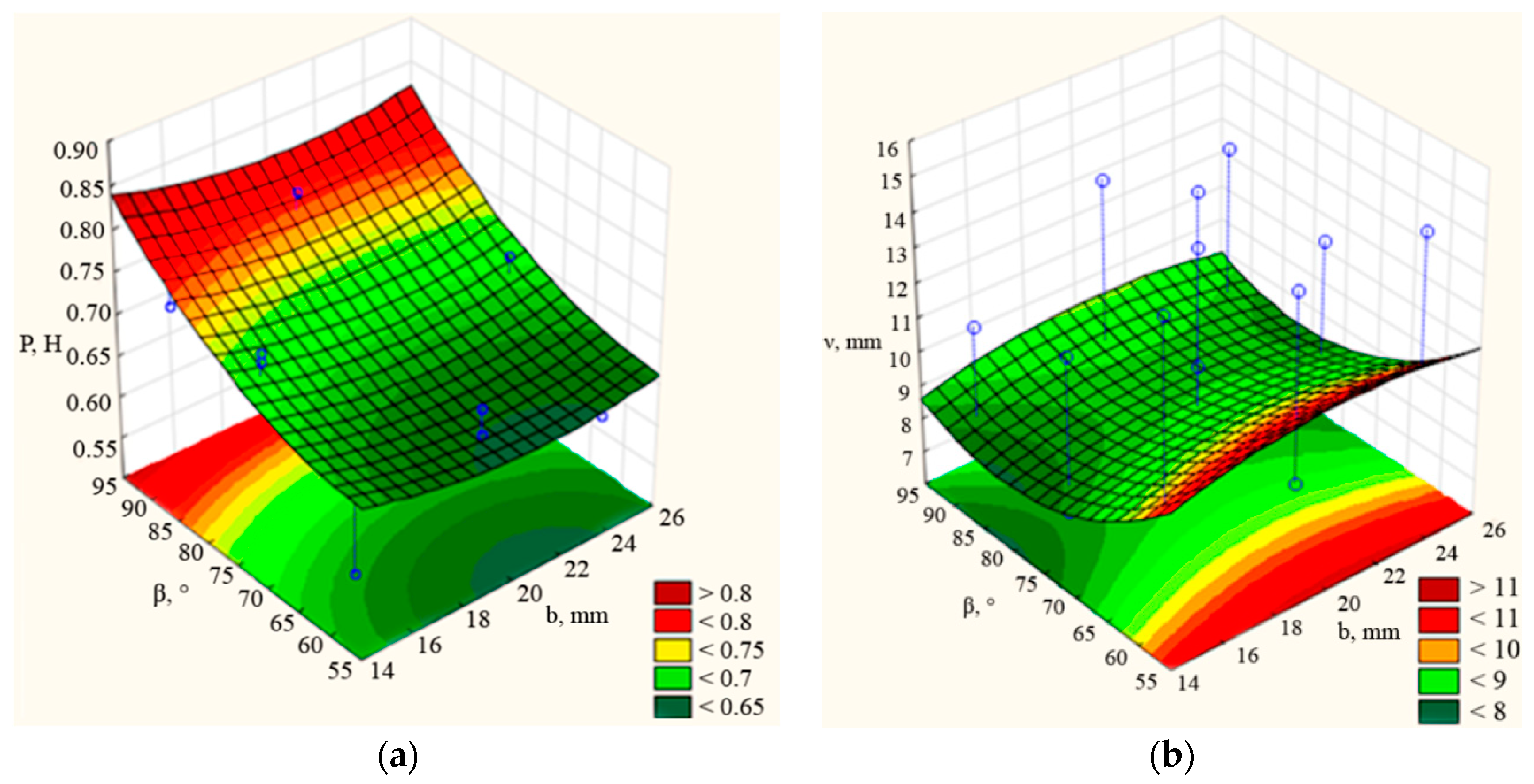
The analysis of the response surfaces, which are 3D graphs of P = f (β, b) dependences, shows that at a chisel length of 130 mm (Figure 9a), the maximum traction force is equal to 0.8 kN and the minimum traction force is 0.65 kN. In this dependence, when the chisel length increases to 145 mm (Figure A1a), the maximum traction force is more than 0.76 kN and the minimum value is less than 0.57 kN. When the length is 160 mm (Figure A2a), the range of traction force value will be the maximum value is more than 1.1 kN, and the minimum value is less than 0.95 kN. This is because as the chisel length increases to 160 mm or decreases to 130 mm, the traction force starts to increase. For the desired traction force value, the optimum mounting angle is 55–70 degrees with a chisel width of 19–23 mm and length of 130–145 mm. When considering the graphs of Figure A1b and Figure A2b, it can be noted that as the chisel length increases (Figure A2a), the dependence of the unevenness of the seed embedment depth on the mounting angle and the chisel width also increases. The hyperbola plots correspond to the response surface of the minimax type, and the optimal values of the variation coefficient of seed embedment depth can be obtained at the maximum width value at 25 mm and the minimum value at 15–16 mm. However, it is required to increase the mounting angle value from 70° to 90°. As a result of analyzing the dependences P = f (b, β) according to the graphs presented in Figure 9a, Figure A1a and Figure A2a, it can be concluded that the longer the chisel length, the higher the value of dependence of the traction force on the mounting angle of the rear part to the horizon (β) and chisel width (b). And in the case of νd = f (b, β) (Figure 9b, Figure A1b and Figure A2b), the greater the chisel length, the smaller will be the dependence value of the seed embedment depth unevenness on the mounting angle of the rear part to the horizon (β) and chisel width (b). Thus, if a length of 130–145 mm is required to reduce the traction force, 130 mm and 160 mm are necessary to reduce the variation coefficient of the seed embedment depth unevenness.
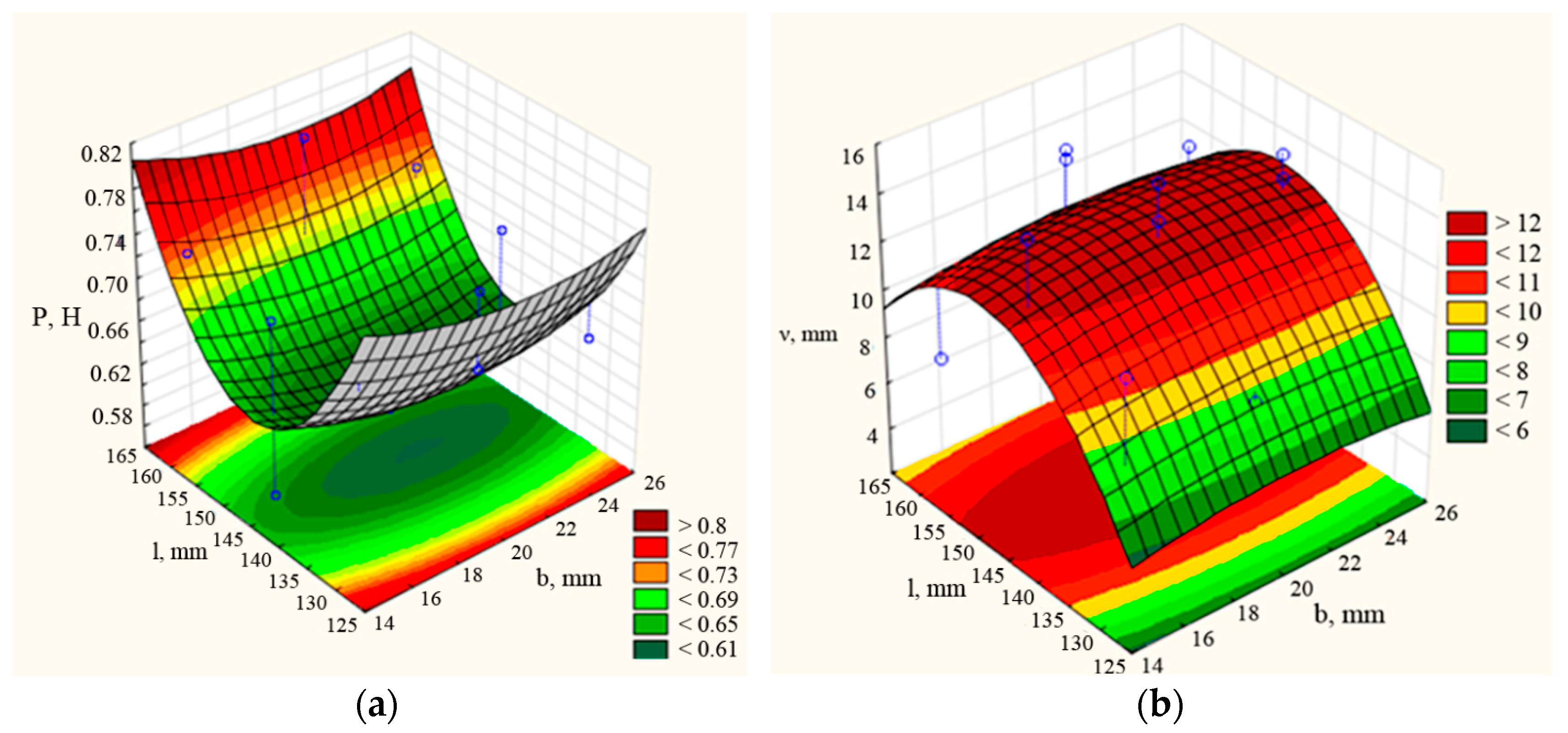
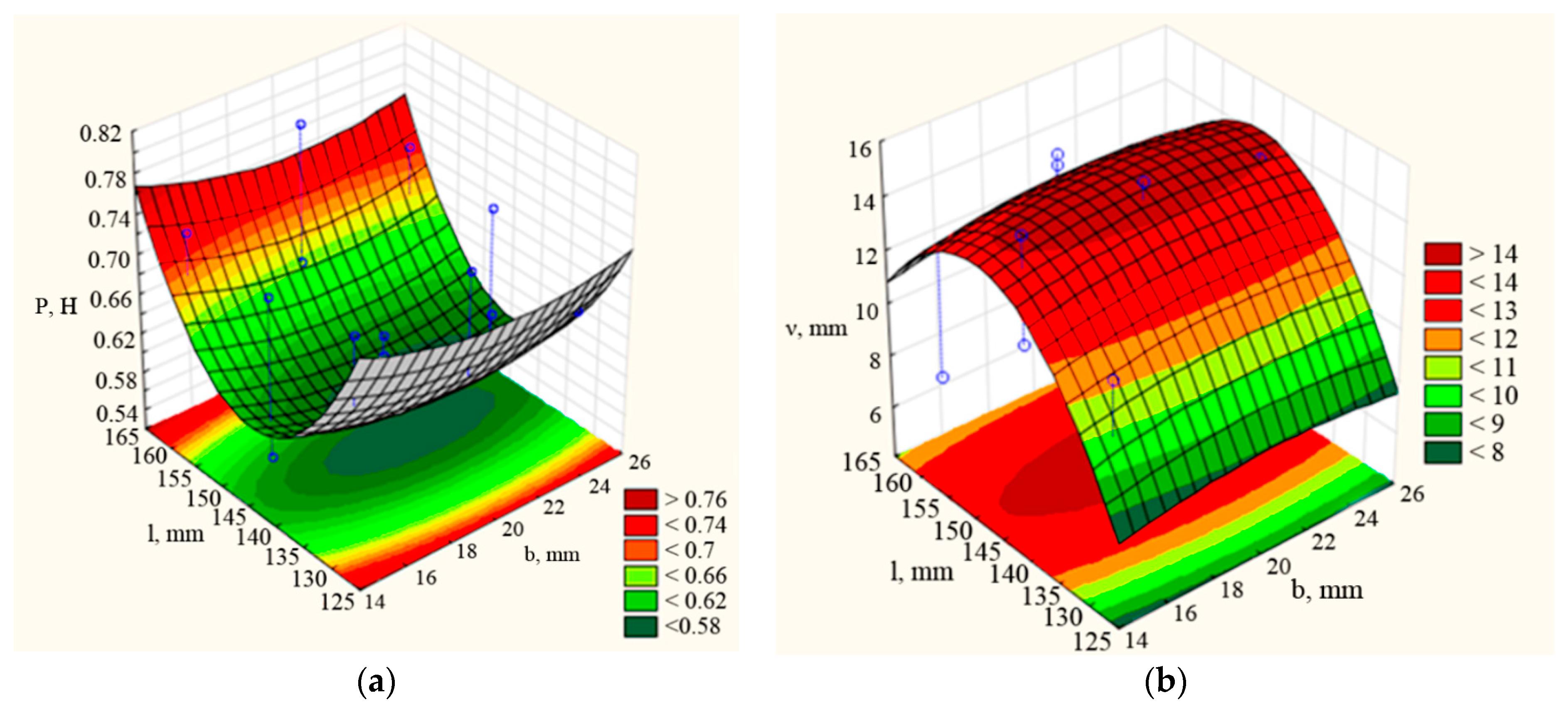
Figure 10 presents the surface responses of dependences P = f (l, b). According to the graphs, it can be noted that with increasing the mounting angle of the rear part to the horizon, the maximum and minimum values of the traction force dependence on the width (b) and length (l) of the coulter chisel also increases. At the value of the mounting angle of the rear part to the horizon β = 70° ÷ 75°, the traction force has optimal values between 0.6 ÷ 0.7 kN, with a maximum value of 0.8 kN. As can be seen from the graphs in Figure 10a, Figure A3a and Figure A4a, the traction force decreases at widths of 18–24 mm and lengths of 140–150 mm. When the mounting angle of the rear part to the horizon increases, the value of dependence of the seed embedment depth unevenness νd on the width (b) and length (l) of the coulter chisel decreases. At the value of the mounting angle of the rear part to the horizon β = 75° ÷ 90°, the seed placement depth unevenness νd have almost the same values (Figure 10b, Figure A3b and Figure A4b). At all ranges of the mounting angle, the optimum value of the variation coefficient is at a length of 125–130 mm. Based on this, it can be concluded that the average width and length values at a mounting angle of 75–90° are required to reduce the traction force. However, at this mounting angle, the seed embedment depth unevenness should be reduced to a minimum value of length. In this case, the tendencies of the chisel width range are irrelevant.
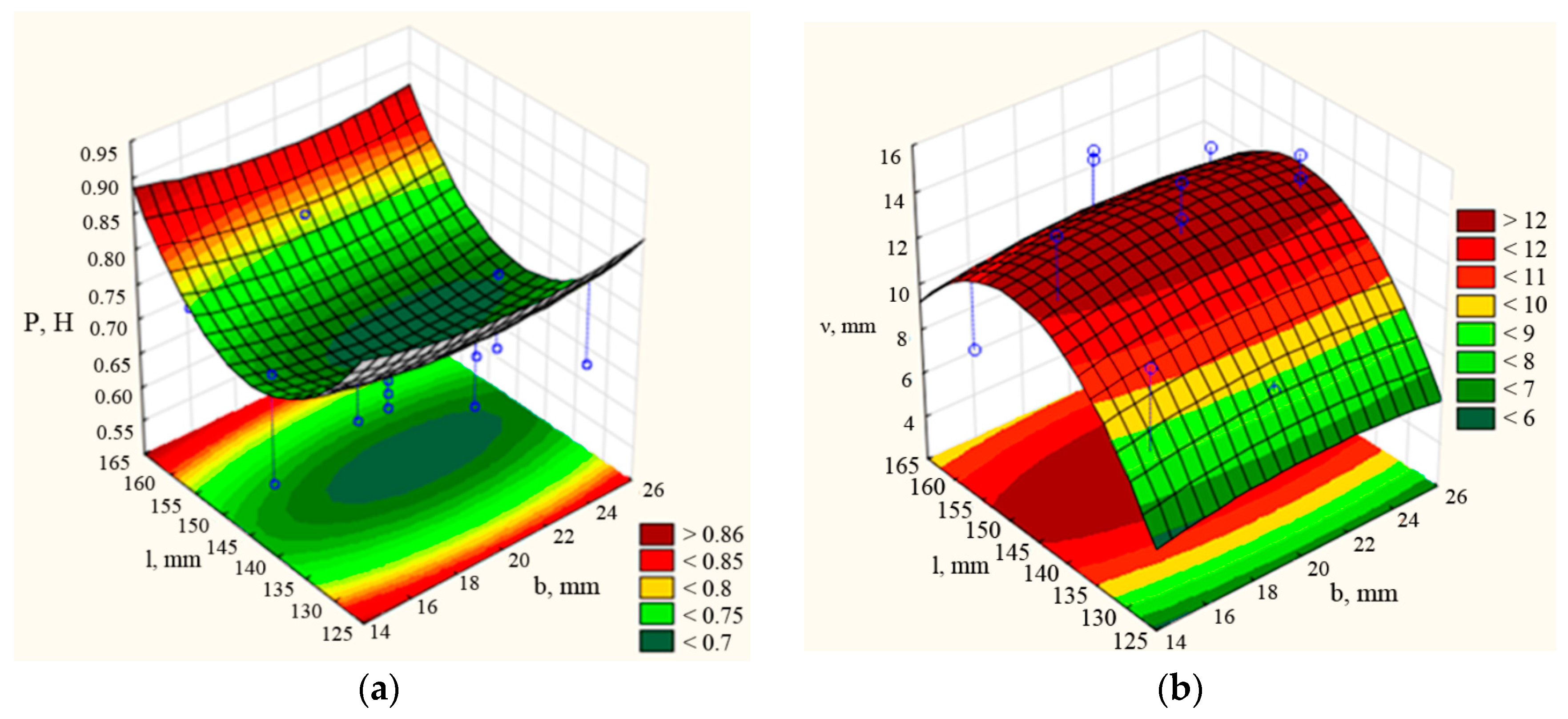
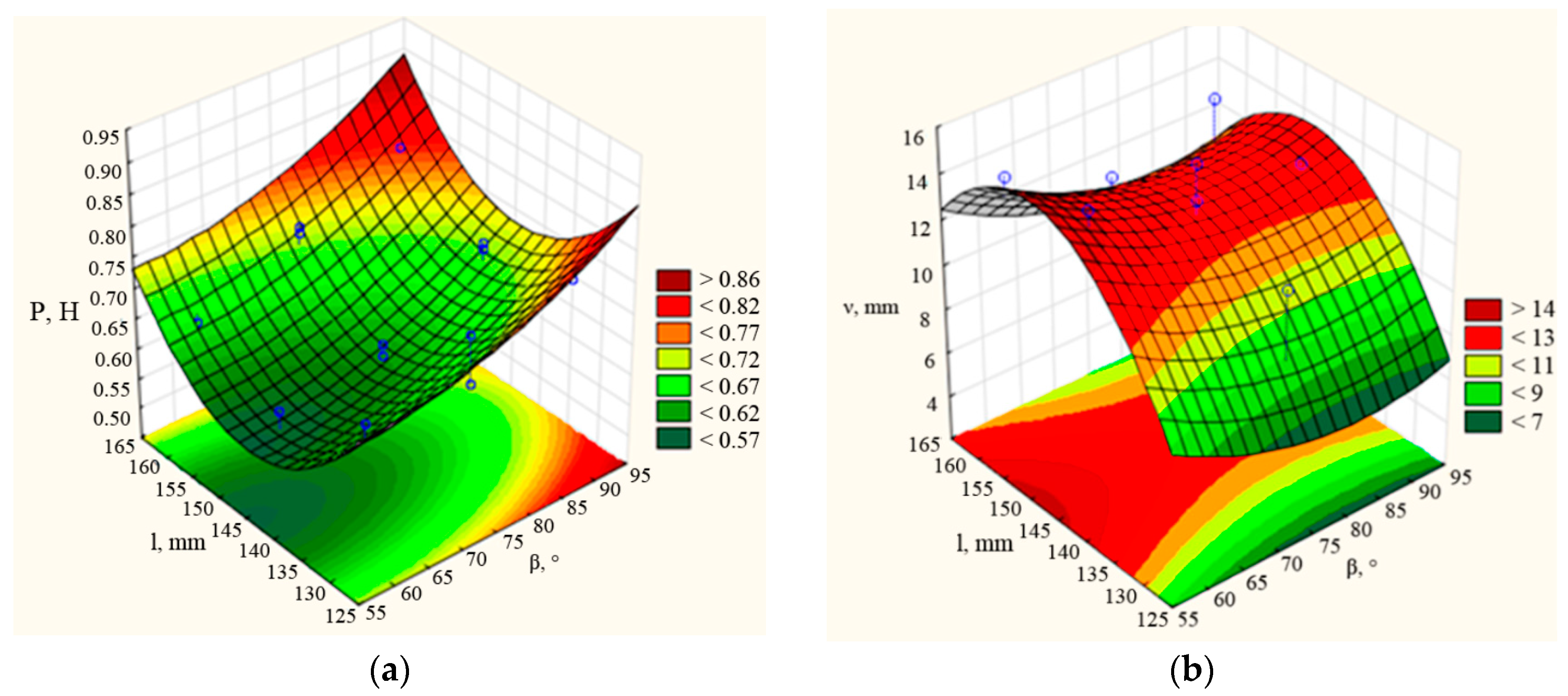
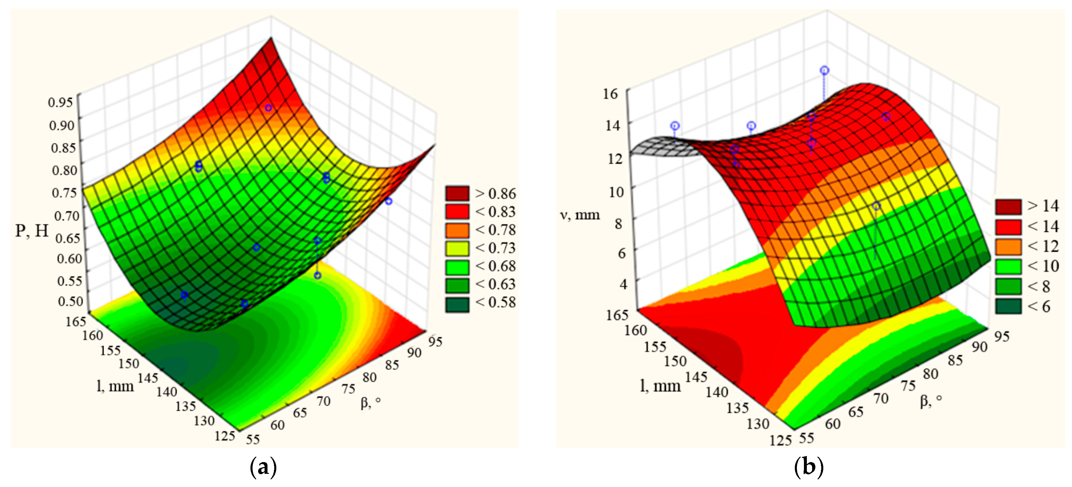
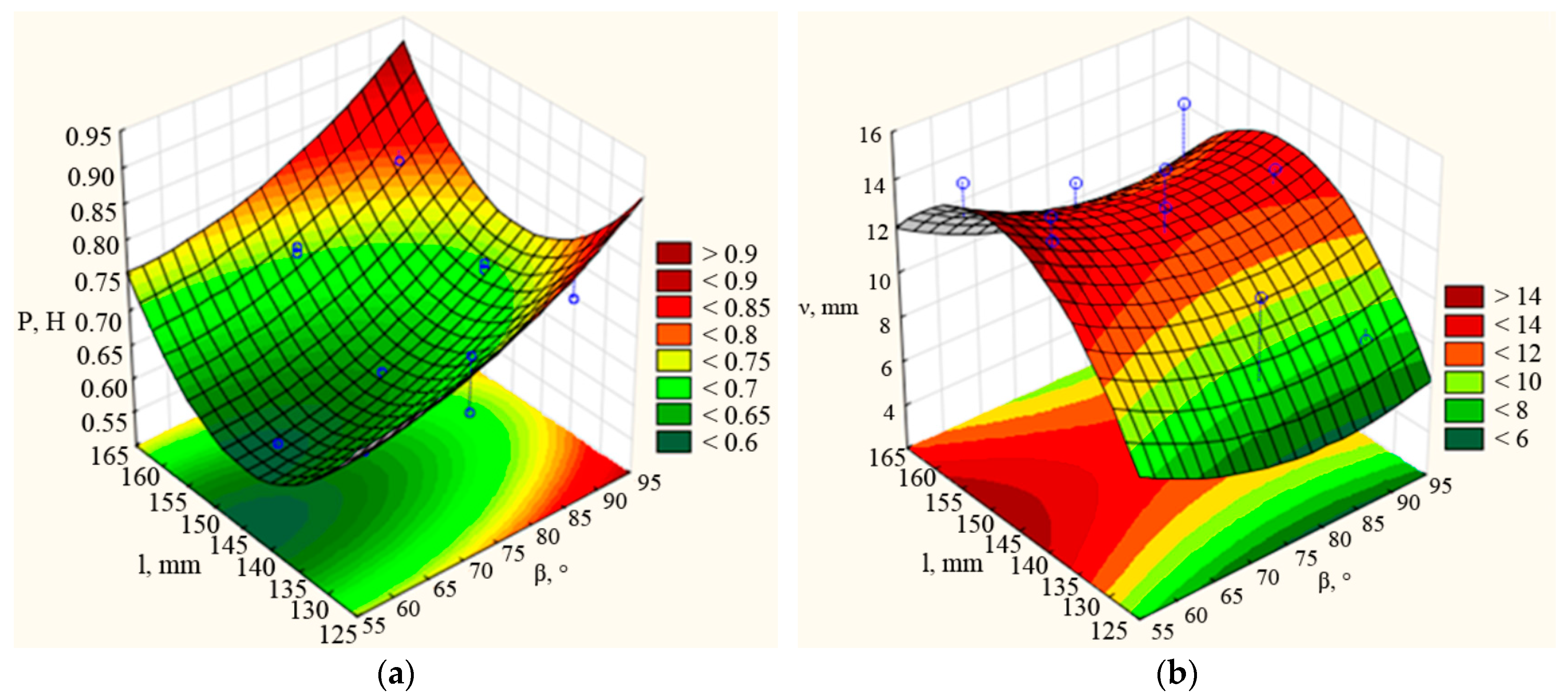
The analysis of the response surfaces of dependences P = f (l, β) shows that at chisel widths of 15 and 25 mm, dependences of traction force on the mounting angle of the rear part to the horizon (β) and length (l) of the coulter chisel increases by a maximum of 0.86 ÷ 0.9 kN and a minimum of more than 0.58 kN, Figure 11. At width value b = 19 ÷ 20 mm, the traction force has optimum values between 0.57 ÷ 0.7 kN, with a maximum value of 0.86 kN. This is explained by the fact that the more the chisel width increases, the dependence of traction force on chisel length and mounting angle decreases (Figure A5a and Figure A6a). To obtain the desired range of traction force, a length of 140–150 mm and a mounting angle of 60–65° at a width of 20 mm, a length of 142–148 mm, and a mounting angle of 60° at a width of 25 mm are required. However, the dependence of the seed embedment depth unevenness νd on the mounting angle (β) and the coulter chisel length (l) have almost the same values in all the width ranges considered. For this function of the seed embedment depth unevenness νd = f (l, β), the length has more values than the mounting angle. Based on the graphs (Figure 11b, Figure A5b and Figure A6b), it can be concluded that the smaller the chisel length, respectively, the smaller will be the variation coefficient of seed embedment depth unevenness.
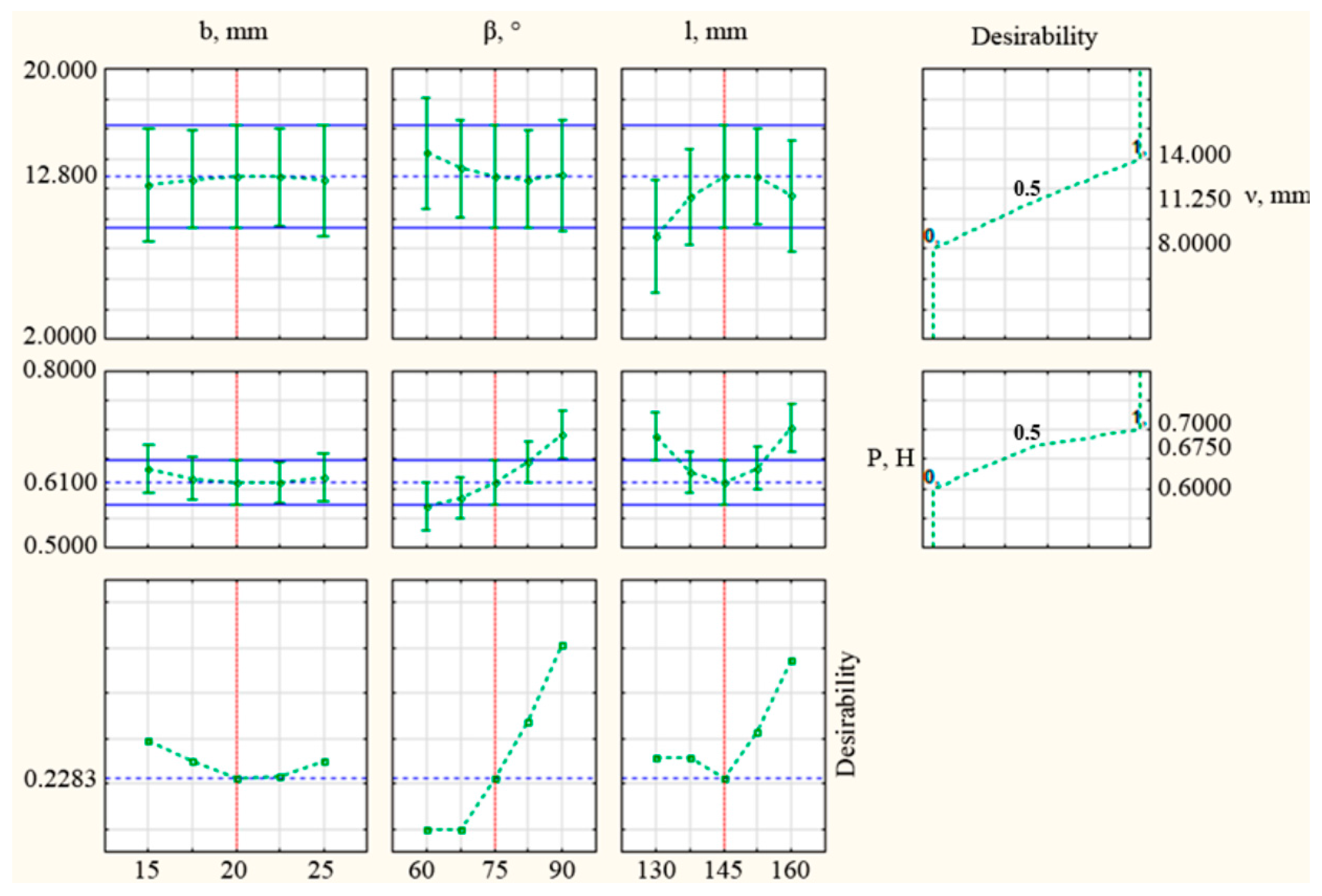
The desired optimum values (Table 5 and Table 6) of the design parameters and the profiles of the predicted values and desirability functions were obtained in the Statistica program (Figure 12).
According to Table 5 and Table 6, the controlled parameter—mounting angle of chisel affects the optimization criteria in the opposite way, i.e., if to reduce the uneven dimensionality of seed embedment it is necessary to reduce the angle, then to reduce the traction force it is necessary to increase this parameter.

3.3. Modeling of Chisel Parameters Using the Finite Element and SPH Methods

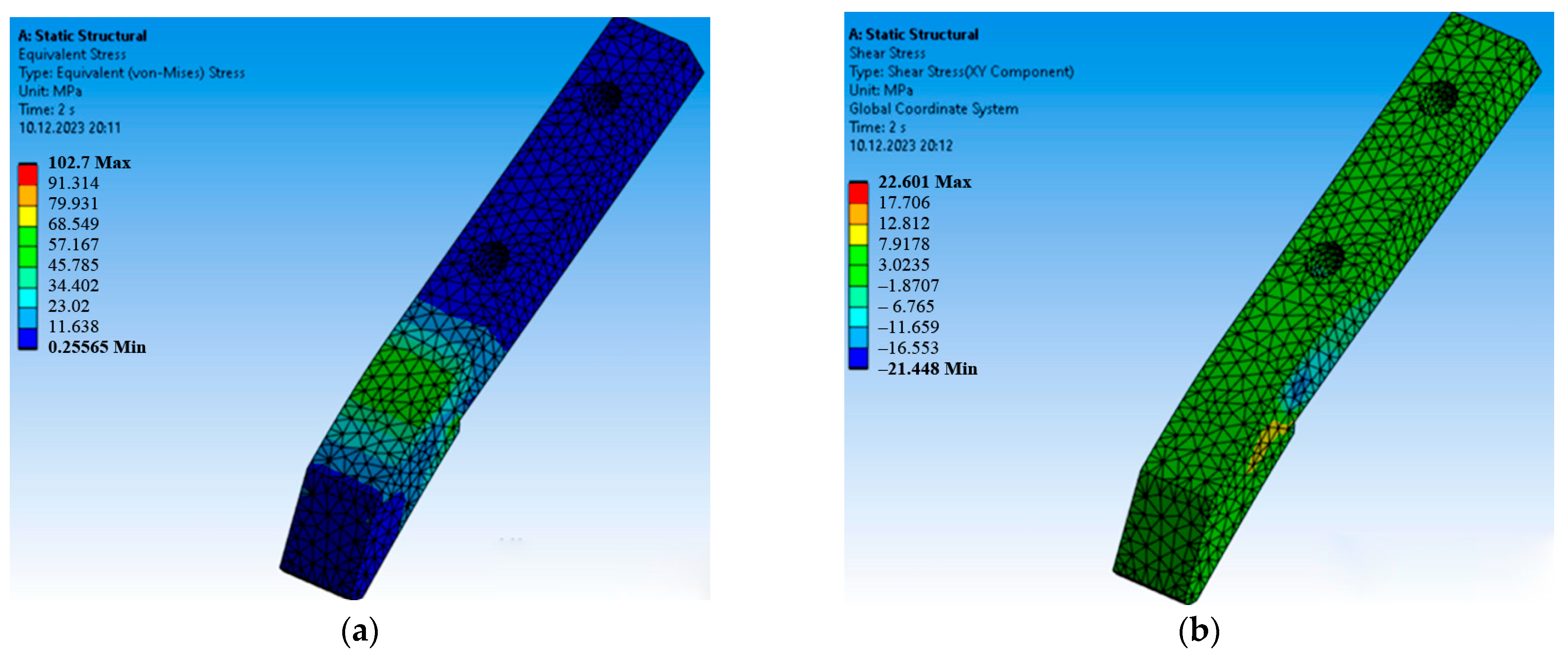
The zone of maximum deformation and dangerous wear is in the nose part of the chisel, as shown in Figure 13a. At the same time, a red-colored hazardous zone is observed, which can lead to cracks and chipping on the chisel. The simulation results show that for the chernozem in the working part, the maximum normal stress is 65.038 MPa (Figure 13b) and the shear stress is 22.601 MPa (Figure 13b and Figure A7a,b). The chisel was loaded directly with the pressure corresponding to the depth of treatment: Pmax = 2.00 MPa, Pmin = 0.7 MPa for chernozem. The distribution of equivalent von Mises stresses on the model subjected to pressure is presented in Figure 13b and Figure A7a,b. During soil embedding, the wear value of the working part is in the cantilever part, which hangs freely from the anchoring point in the rack. According to the modeling results in ANSYS, it can be concluded that the soil of the chernozem type (dark chestnut soils with moisture content of 25–45%, soil clogging with stones with an average diameter of 50 mm was 0.6–1.5 pcs/m2) can take high yield or shear stresses due to the strength of bonding between particles or between particles and aggregates, which leads to small deformations in these types of textures. The investigated width of the seeder implement corresponds to the soil type and pressure presented.
The next task in modeling was to exclude turf swelling in places after the pass and to justify the geometric parameters and mounting angles of the chisel. To solve this problem in modeling, the SPH method in LS-DYNA was applied. The width of 20 mm and the mounting angle of 75° were taken as the chisel’s geometrical parameters.
The effective stress in the soil increases as the contact area between the chisel and the soil increases during the soil-cutting process. When the soil is destroyed completely, the effective stress reaches a stable value. During the soil-cutting process, the maximum effective stress on the soil is 2.788 Pa. From Figure 14, it can be noted that the free part of the chisel is more subjected to deformation and wear during embedding. During the initial penetration of the working body into the soil, soil compaction can be seen in the furrow and in the front cantilever part. While traction force value increases at widths of 15 mm and 25 mm, the variation coefficient of embedment depth unevenness decreases, so the optimum value of chisel width is 20.97 mm (Table 2). Increasing the mounting angle of the chisel decreases both optimization criteria. The optimal desired mounting angle response is 81.6° (Table 2). Chisel length has a parabola-like curve inflection; if at chisel lengths 130 and 145 mm, the value of traction force increases, the variation coefficient at these ranges’ decreases, and the optimum length is 148.9 mm. Based on these graphs, it is possible to note the opposite influence of factors on traction force and variation coefficient of embedment depth.

3.4. Traction Force of the Working Body in the Soil Bin

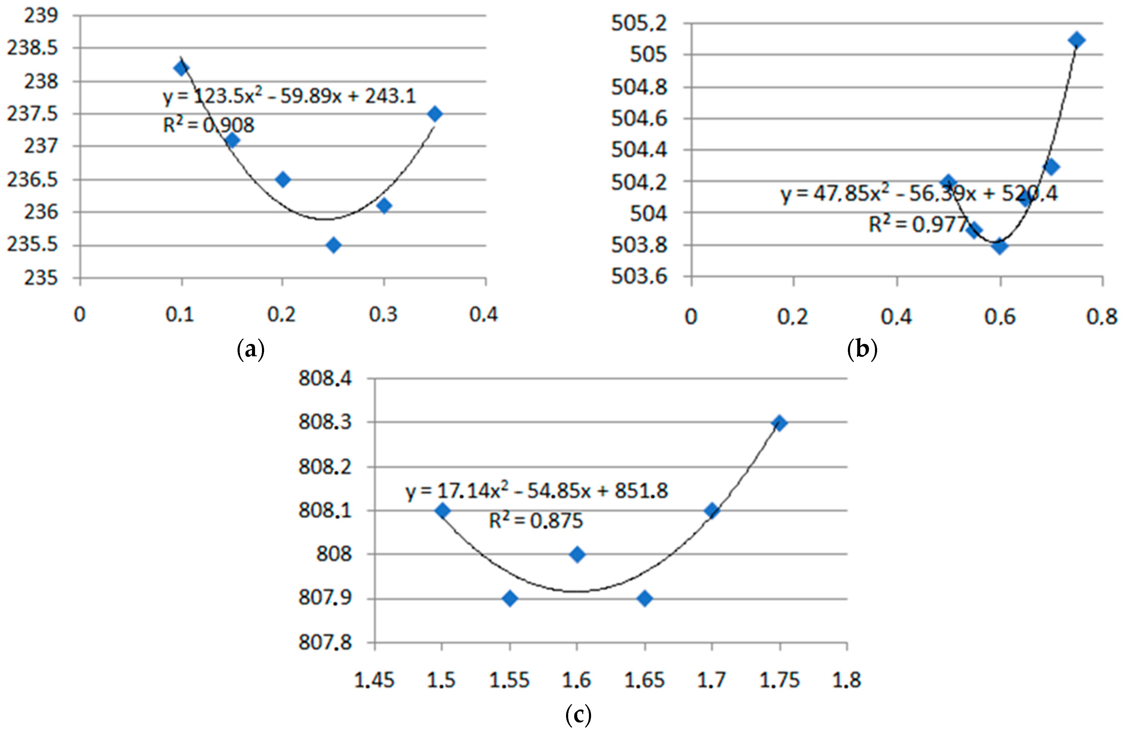
The coulter manufactured with the specified parameters was tested on the soil bin, and the data characterizing the dependence of the experimental coulter’s traction resistance on its design and technological parameters at different speed modes were obtained (Figure 15). According to the approximation [34,35] of the experimental data, the dependence of the experimental coulter’s traction resistance on the forward speed was obtained. The red and green lines are expected traction load intervals before the study and don’t have the negative influence on the results. According to the dynamometry result, the force of one working body, with a working depth of 0.1 m, varied from 790 to 838 N at maximum speed (Figure 15a). At minimum speed, the range of traction force was 230–280 N (Figure 15b).
The variation of traction force as a function of speed has a parabolic character (Figure 16).

3.5. Seeder Traction Force in Field Conditions

As the experiments have shown, a significant influence on the value of traction resistance of the seeder with experimental working bodies is the speed of the machine. Analysis of the obtained data, according to Figure 17, indicates that the traction resistance dependence of the seeder coulter’s experimental sample on the speed is straight, and the theoretical data are in sufficient agreement with the experimental data. As the speed increases from 3.7 to 8 km/h, the traction resistance of the seeder’s experimental sample increases from 8.274 kN to 8.631 kN. The decrease in traction force of the seeder at the mounting angle 75° relative to the horizon is explained by the reduction in the length of its working surface.

3.6. Unevenness of Seeder Depth in Field Conditions

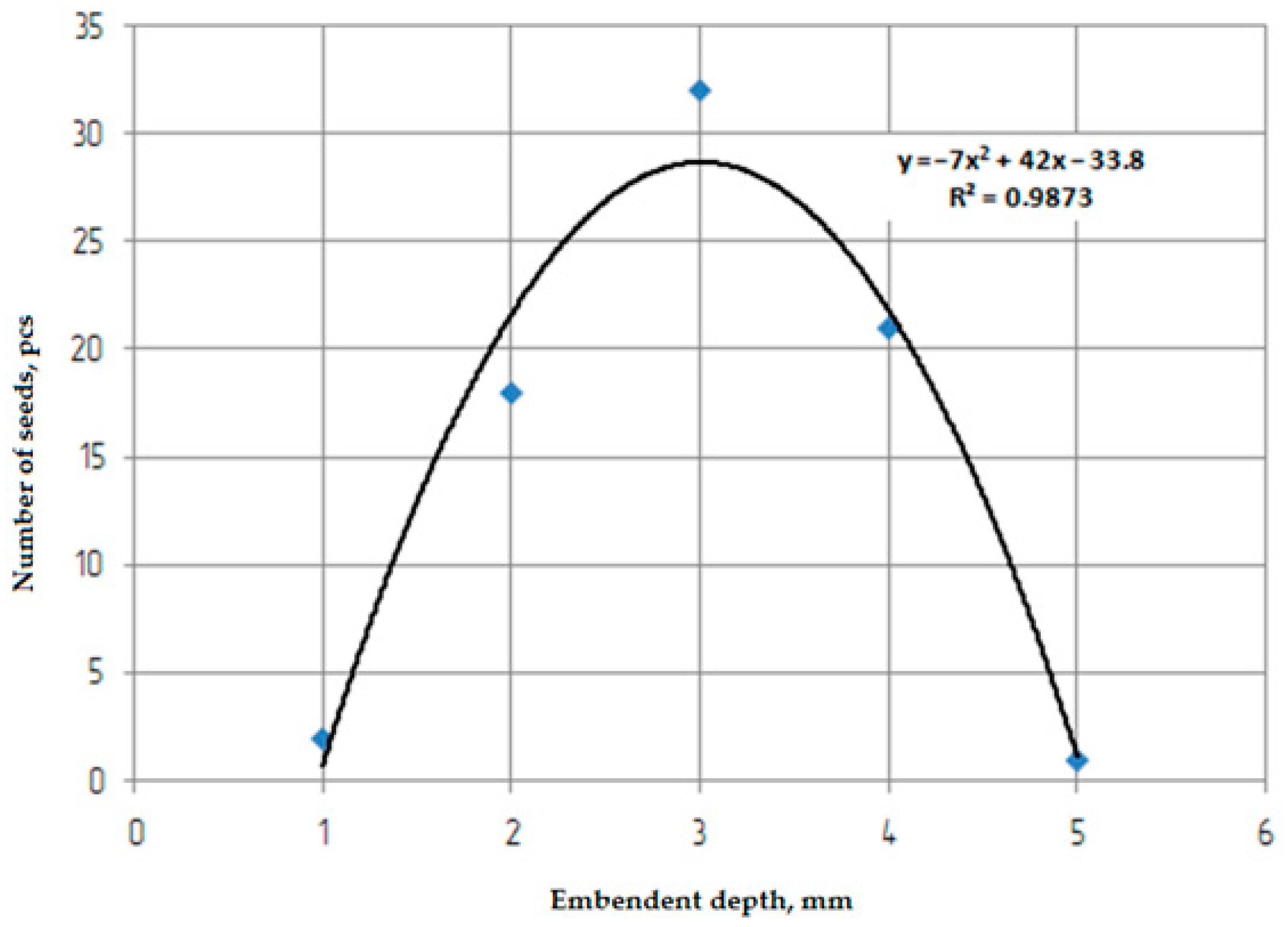
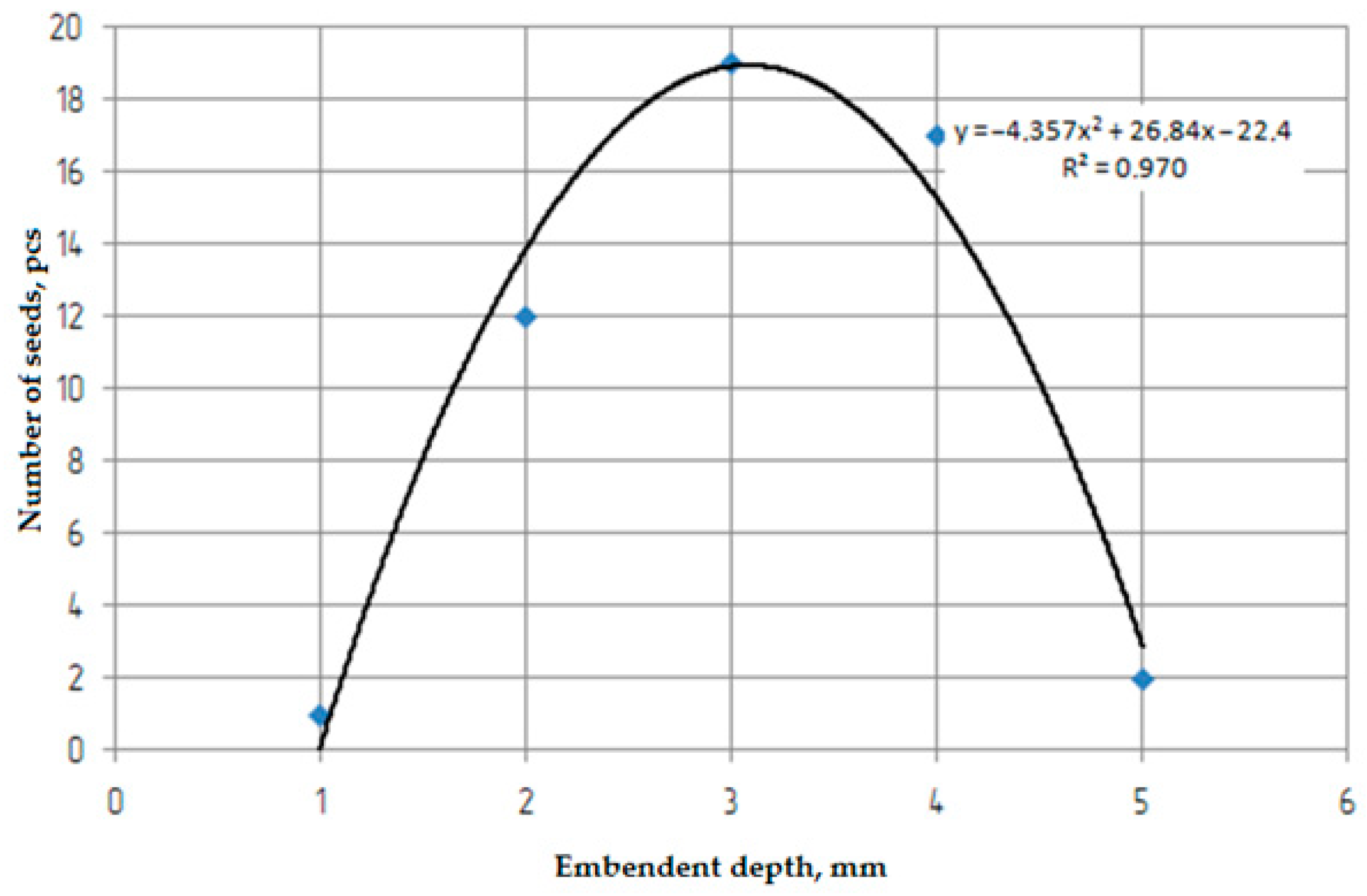
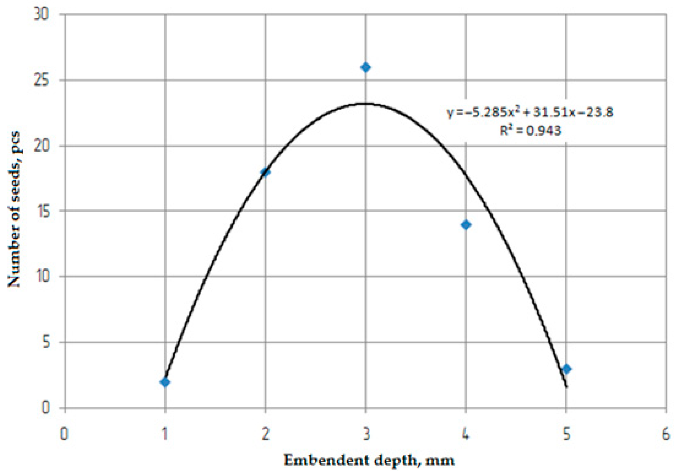
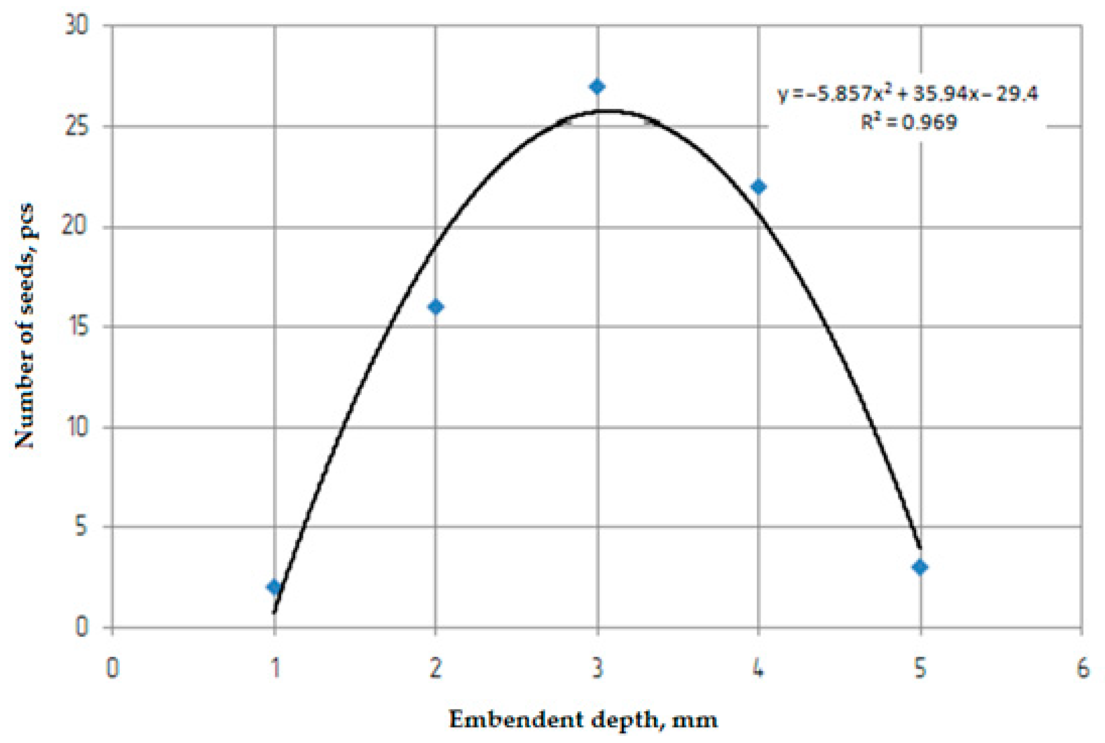
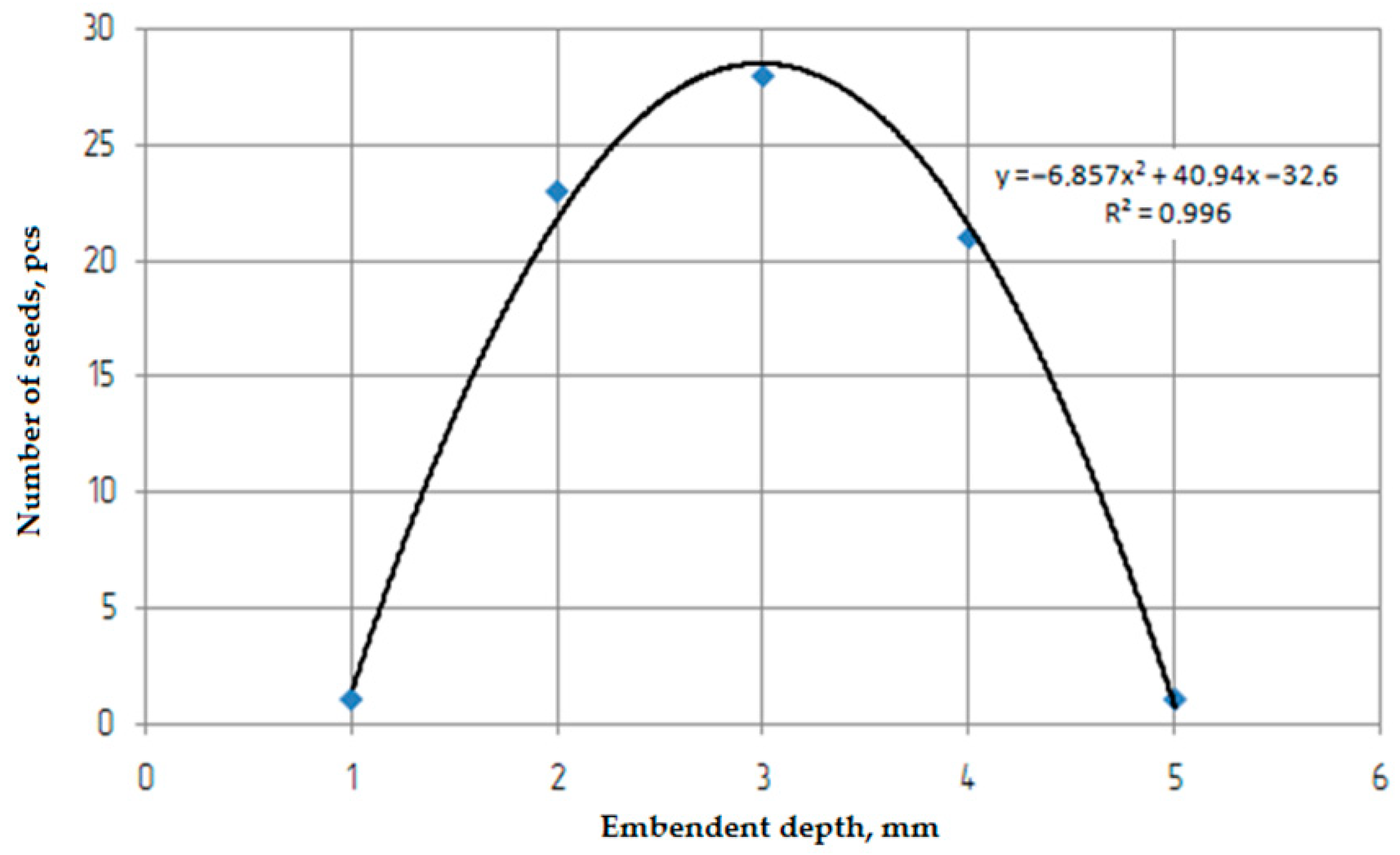
The following statistical characteristics were determined from the obtained data: average actual embedment depth of grass seeds on the sod, standard deviation, unevenness by depth (coefficient of variation), and sampling error of the average sample. The main results of the field tests are presented in Figure 18 and Figure A8, Figure A9, Figure A10, Figure A11. The graphs show that the melilot seeds are mostly located at a depth of 1.8–4 cm with variation coefficients of 19–36%, Figure 18. The wheatgrass seeds are located at a depth of 2–4.2 cm with a variation coefficient of 15–35%, Figure A8. The magnitude of the coefficient of variation (19–35%) of the location at a depth of 2–4 cm indicates a satisfactory dispersal of aweless bromegrass seeds, Figure A9. Alfalfa seed sowing also showed satisfactory dispersibility, having an embedment depth unevenness ranging from 13 to 36% at depths of 1.8–4 cm, Figure A10. Sainfoin seed dispersal has a normal distribution law, with a variation coefficient of 18–35% at depths of 2–3 cm, Figure A11. Relatively high variation coefficients of seed location by embedment depth are explained by the relief of the sod not being prepared for sowing, the soil hardness, and its influence on the stability of the experimental grain–fertilizer–grass seeder movement.

4. Discussion

All research methods and results related to traction force and unevenness of seed placement depth dependencies on working body structural and technological parameters in previous studies were comparable or equivalent to the method used in this study. The scientific novelty of this research is the substantiation of technological and structural coulter parameters for direct sowing of agricultural crops under cover crops and in turf; revealing the interaction regularity of the experimental sample of the embedding working body with the soil, and also obtaining the dependence of the coulter traction force on the parameters of the cultivated soil layer and its physical and mechanical characteristics, translational speed of the working body, and its mounting angles, solution, and friction.
In studies [23,26,29,31,32], the coulter angles of 90° and 53° on loamy field soil were adopted. In comparative analyses, the straight coulter with an inclination angle of 53° showed decreased furrow filling and increased lateral soil ejection. However, when testing the chisel of a mock-up sample of a grain–fertilizer–grass seeder with a mounting angle on the shank at 60° [34,35], it was found that when cutting a slot, there is swelling of turf and dried soil crusts. In the [24], it was found that the furrow size depends on the mounting angle of the lateral blade. Researchers [21] tested the tool in a soil bin and the DEM method by simulation when determining the mounting angle of the tool for soil immersion. When testing the implement for 300 mm depth machining, the mounting angles of 5°, 12°, 19°, 26°, and 33° were selected. The tool with a 26° mounting angle had the largest soil disturbance area, comparatively lower soil disturbance ratio, soil surface density, and traction, and higher soil loosening efficiency. However, the authors of these works [26,29,30,31] modeled the influence of the coulter angle (35–90°), and based on the results of comparison with previous studies in sandy loam soil, they found a twofold reduction in traction at a coulter angle of 71°. Therefore, this mathematical modeling adopted the mounting angles of the rear end to the horizon at 60°, 75°, and 90°.
The chisel width [26] was 30 mm, and since this width left an open furrow in the trace, for modeling, the adopted width values were 15, 20, and 25 mm, and the lengths were 130, 145, and 160 mm. At the adopted values of width 20÷25 mm and mounting angles 60° ÷ 75°, the traction force was 0.62 ÷ 0.8 Kn. According to the results of finite element modeling in SOLIDWORKS and ANSYS programs, the chisel cantilever part is more exposed to stresses and wear during soil embedment. The 20 mm and 25 mm widths have the most significant resistance to normal deformation and shear along the coordinate axes. Considering previous studies’ results [26,29,30,31,34,35], the following parameters were accepted for SPH method modeling in the LS-DYNA program: chisel width—20 mm, length—145 mm, and mounting angle—75°. In this desired range of coulter chisel parameters, the value of traction force will be within 0.74 ÷ 0.8 Kn. During the cutting process with the chisel with the adopted parameters, the soil is cut relatively stably, and the effective stress on the soil occurs in the working cutting zone. However, soil compaction in the front chisel cantilever part has been noticed, which can lead to rapid wear of the working body; therefore, during testing, chisels were hardened by different methods for comparison.
According to the above, the parameters of the coulter chisel of grain–fertilizer–grass seeders should have the following values: coulter chisel width b = 20–21 mm, mounting angle the rear part to the horizon β = 70–80°, and chisel length l = 140–150 mm.

5. Conclusions

The purpose of this work was to reduce traction force and ensure uniformity of seeding depth by justifying the optimal parameters of the coulter chisel. The results of theoretical and experimental studies showed that the speed, chisel width, mounting angle, and seed embedment depth had the most significant effect on the traction force. The optimal coulter chisel parameters that were obtained and optimized using ANSYS LS-Dyna provide a minimum traction force and a stable technological process of sowing hard-to-sow grass seeds at depths of 1.8–6 cm. The theoretical values of traction force are in sufficient accordance with the experimental data, and they varied between 8.27 and 8.39 Kn.
The seed embedment depth uniformity showed that melilot seeds (1.8–4 cm), wheatgrass (2–4.2 cm), awnless bromegrass (2–4 cm), alfalfa (1.8–4 cm), and sainfoin (2–3 cm) are located at the corresponding depths with an unevenness of 18–36%. Relatively high coefficients of variation of sown seed arrangement (depth) are explained by the relief of turf not prepared for sowing, soil hardness, and its influence on the stability of the experimental grain–fertilizer–grass seeder movement.
The modeled deformation-stress state of coulter chisel from the design parameters of the chisel allows for the effective agrotechnical and mechanical predictions regarding the occurrence of residual stresses and the working lifetime of the seeder working body.
In conclusion, the reduction in traction force by improving the design and technological parameters, as well as surface hardening, are positive influences on sowing productivity. The surface hardening methods of chisel to enhance the durability and chisel wear resistance will be investigated in future studies.

Author Contributions

Conceptualization, S.N. and D.K.; methodology, S.N. and D.K.; software, D.K. and A.S.; validation, M.R. and K.T. (Khozhakeldi Tanbayev); formal analysis, D.K. and I.M.; investigation, D.K., K.T. (Kaldybek Tleumbetov) and I.M.; resources, A.S., Y.A. and K.T. (Kaldybek Tleumbetov); data curation, M.R., Y.A. and K.T. (Kaldybek Tleumbetov); writing—original draft preparation, D.K.; writing—review and editing, S.N.; visualization, A.S. and K.T. (Khozhakeldi Tanbayev); supervision, S.N. and M.R.; project administration, S.N.; funding acquisition, S.N. All authors have read and agreed to the published version of the manuscript.

Funding

This research was funded by the Science Committee of the Ministry of Science and Higher Education of the Republic of Kazakhstan, Grant No. AP05134800.

Data Availability Statement

The original contributions presented in the study are included in the article further inquiries can be directed to the corresponding author.

Conflicts of Interest

The authors declare no conflicts of interest.

Appendix A

Table A1. Levels and intervals of variation of factors.
FactorsUnitCode DesignationVariation IntervalsNatural Factor Levels
Corresponding to Coded
−1.682−10+1+1.682
b—the coulter chisel widthmmx151015202530
β—the mounting angledegreex21545607590105
l—the coulter chisel lengthmmx315115130145160175
Table A2. Planning matrix and results.
Experiment Number x 0 x 1 x 2 x 3 x 1 x 2 x 1 x 3 x 2 x 3 x 1 x 2 x 3 x 1 2 x 2 2 x 3 2 Pνd
1234567891011121314
1234567891011121314
1111111111110.5615
2111−11−1−1−11110.614
311−11−11−1−11110.7211
411−1−1−1−1111110.7113
51−111−1−11−11110.7412
61−11−1−111−11110.667.7
71−1−111−1−111110.737.5
81−1−1−1111−11110.7212
911.6820000002.829000.688.5
101−1.6820000002.829000.758
11101.6820000002.82900.6514
1210−1.6820000002.82900.7913.6
131001.6820000002.8290.6115
14100−1.6820000002.8290.5913.4
15100000000000.6310
16100000000000.78.9
17100000000000.6611.5
18100000000000.6512
19100000000000.610
20100000000000.6213
sum20000002−213.65813.65813.65813.37230.1

Appendix B

Figure A1. Dependences of traction force P and seed embedding depth unevenness H on the mounting angle of the rear part to the horizon (β) and chisel width (b) at length at l = 145 mm: (a) P = f (b, β); (b)   ν d = f (b, β).
Agriengineering 06 00136 g0a1
Figure A2. Dependences of traction force P and seed embedding depth unevenness H on the mounting angle (β) and chisel width (b) at length at l = 160 mm: (a) P = f (b, β); (b) ν d = f (b, β).
Agriengineering 06 00136 g0a2
Figure A3. Dependences of traction force P and seed embedding depth unevenness νd on the length (l) and width (b) of the coulter chisel at the mounting angle β = 75°: (a) P = f (l, b); (b) ν d = f (l, b).
Agriengineering 06 00136 g0a3
Figure A4. Dependences of traction force P and seed embedding depth unevenness νd on the length (l) and width (b) of the coulter chisel at mounting angle β = 90°: (a) P = f (l, b); (b) ν d = f (l, b).
Agriengineering 06 00136 g0a4
Figure A5. Dependences of traction force P and the seed embedment depth unevenness νd on the length (l) of the coulter chisel and the mounting angle (β) at different chisel width b = 20 mm: (a) P = f (l, β); (b) ν d = f (l, β).
Agriengineering 06 00136 g0a5
Figure A6. Dependences of traction force P and seed embedment depth unevenness νd on the length (l) of the coulter chisel and the mounting angle (β) at different chisel width b = 25 mm: (a) P = f (l, β); (b) ν d = f (l, β).
Agriengineering 06 00136 g0a6
Figure A7. Unit and tangential stresses: (a) equivalent (von Mises) stress; (b) shear stress.
Agriengineering 06 00136 g0a7
Figure A8. Wheatgrass seed sowing.
Agriengineering 06 00136 g0a8
Figure A9. Awnless bromegrass seed sowing.
Agriengineering 06 00136 g0a9
Figure A10. Alfalfa seed sowing.
Agriengineering 06 00136 g0a10
Figure A11. Sainfoin seed sowing.
Agriengineering 06 00136 g0a11

References

  1. Nukeshev, S.; Eskhozhin, K.; Karaivanov, D.; Sankibaev, T.; Kakabayev, N. Theoretical and Experimental Substantiation of the Design of an Opener for Intrasoil Broadcast Sowing of Grain Crops. Bulg. J. Agric. Sci. 2016, 22, 862–868. [Google Scholar]
  2. He, S.; Qian, C.; Jiang, Y.; Qin, W.; Huang, Z.; Huang, D.; Wang, Z.; Zang, Y. Design and Optimization of the Seed Feeding Device with DEM-CFD Coupling Approach for Rice and Wheat. Comput. Electron. Agric. 2024, 219, 108814. [Google Scholar] [CrossRef]
  3. Hou, S.; Zhu, Y.; Zhu, X.; Wang, Y.; Ji, W.; Chen, H. Design and Experiment of a Straw Clearing Mulching No-Tillage Planter. Biosyst. Eng. 2022, 221, 69–80. [Google Scholar] [CrossRef]
  4. Romanyuk, N.; Ednach, V.; Nukeshev, S.; Troyanovskaya, I.; Voinash, S.; Kalimullin, M.; Sokolova, V. Improvement of the Design of the Plow-Subsoiler-Fertilizer to Increase Soil Fertility. J. Terramechanics 2023, 106, 89–93. [Google Scholar] [CrossRef]
  5. Malikov, V.; Ishkov, A.; Shevtsova, L.; Katasonov, A.; Tihonskii, N.; Kozlova, V. The Stress-Strain State of the 3D Models Lancet Paw. Transp. Res. Procedia 2022, 63, 2781–2788. [Google Scholar] [CrossRef]
  6. Eskhozhin, K.; Hukeshev, S.; Eskhojin, D. Karaivanov, Dimitar Stress Distribution in Soil under Action of Paraplow Ripper. Life Sci. J. 2014, 11, 20–24. [Google Scholar]
  7. Battiato, A.; Diserens, E. Tractor Traction Performance Simulation on Differently Textured Soils and Validation: A Basic Study to Make Traction and Energy Requirements Accessible to the Practice. Soil Tillage Res. 2017, 166, 18–32. [Google Scholar] [CrossRef]
  8. Zhang, S.; Jia, X.; Dong, J.; Wang, X.; Zhao, H.; Chen, X.; Zhang, Z.; Huang, Y.; Shi, J. Optimization of Operating Angles of Disc Coulters for Maize Residue Management Using Discrete Element Method. Comput. Electron. Agric. 2024, 218, 108691. [Google Scholar] [CrossRef]
  9. Nukeshev, S.; Slavov, V.; Kakabayev, N.; Amantayev, M. Mathematical Modelling in 3D of Opener with Scatterer of the Grain-Fertilizer Seeder. Mechanika 2019, 24, 840–844. [Google Scholar] [CrossRef]
  10. Conte, O.; Levien, R.; Trein, C.R.; Mazurana, M.; Debiasi, H. Resistência Mecânica Do Solo e Força de Tração Em Hastes Sulcadoras de Semeadoras-Adubadoras Em Sistema de Integração Lavoura-Pecuária. Eng. Agríc. 2008, 28, 730–739. [Google Scholar] [CrossRef]
  11. Damanauskas, V.; Janulevičius, A. Differences in Tractor Performance Parameters between Single-Wheel 4WD and Dual-Wheel 2WD Driving Systems. J. Terramechanics 2015, 60, 63–73. [Google Scholar] [CrossRef]
  12. Barbosa, L.A.P.; Magalhães, P.S.G. Tire Tread Pattern Design Trigger on the Stress Distribution over Rigid Surfaces and Soil Compaction. J. Terramechanics 2015, 58, 27–38. [Google Scholar] [CrossRef]
  13. Moitzi, G.; Haas, M.; Wagentristl, H.; Boxberger, J.; Gronauer, A. Energy Consumption in Cultivating and Ploughing with Traction Improvement System and Consideration of the Rear Furrow Wheel-Load in Ploughing. Soil Tillage Res. 2013, 134, 56–60. [Google Scholar] [CrossRef]
  14. Silva, P.R.A. Mecanismos Sulcadores de Semeadora-Adubadoracultura do Milho (Zea mays L.) no Sistema de Plantio Direto. Master’s Thesis, Universida de Estadual Paulista “Júlio de Mesquita Filho”, Botucatu, Brazil, 2003. [Google Scholar]
  15. Levien, R.; Furlani, C.E.A.; Gamero, C.A.; Conte, O.; Cavichioli, F.A. Semeadura Direta de Milho Com Dois Tipos de Sulcadores de Adubo, Em Nível e No Sentido Do Declive Do Terreno. Cienc. Rural 2011, 41, 1003–1010. [Google Scholar] [CrossRef]
  16. Seki, A.S.; Benez, S.H.; Arbex Da Silva, P.R. Desempenho Operacional de Semeadora e Produtividade Do Milho em Plantio Direto e Cultivo Mínimo. EnergAgric 2012, 27, 1. [Google Scholar] [CrossRef]
  17. Wang, X.; Zhu, R.; Huang, Y. Discrete Element Simulations and Experiments of Soil Disturbance Behaviours as Affected by the Upward Angle of Subsoiler’s Wing. In Proceedings of the 2019 ASABE Annual International Meeting, St. Joseph, MI, USA, 7–10 July 2019; p. 1900390. [Google Scholar]
  18. Wang, X.; Gao, P.; Yue, B.; Shen, H.; Fu, Z.; Zheng, Z.; Zhu, R.; Huang, Y. Optimisation of Installation Parameters of Subsoiler’ Wing Using the Discrete Element Method. Comput. Electron. Agric. 2019, 162, 523–530. [Google Scholar] [CrossRef]
  19. Li, B.; Chen, Y.; Chen, J. Comparison of Two Subsoiler Designs Using the Discrete Element Method (DEM). Trans. ASABE 2018, 61, 1529–1537. [Google Scholar] [CrossRef]
  20. Wang, X.; Fu, Z.; Zhang, Q.; Huang, Y. Short-Term Subsoiling Effects with Different Wing Mounting Heights before Winter Wheat on Soil Properties and Wheat Growth in Northwest China. Soil Tillage Res. 2021, 213, 105151. [Google Scholar] [CrossRef]
  21. Wang, X.; Zhou, H.; Ji, J. Effect of Mounting Angle on Bending Subsoiling Tool–Soil Interactions Using DEM Simulations. Agriculture 2022, 12, 1830. [Google Scholar] [CrossRef]
  22. AAskari, M.; Shahgholi, G.; Abbaspour-Gilandeh, Y.; Tash-Shamsabadi, H. The Effect of New Wings on Subsoiler Performance. Appl. Eng. Agric 2016, 32, 353–362. [Google Scholar] [CrossRef]
  23. Ucgul, M.; Fielke, J.M.; Saunders, C. 3D DEM Tillage Simulation: Validation of a Hysteretic Spring (Plastic) Contact Model for a Sweep Tool Operating in a Cohesionless Soil. Soil Tillage Res. 2014, 144, 220–227. [Google Scholar] [CrossRef]
  24. Wang, X.; Zhang, S.; Pan, H.; Zheng, Z.; Huang, Y.; Zhu, R. Effect of Soil Particle Size on Soil-Subsoiler Interactions Using the Discrete Element Method Simulations. Biosyst. Eng. 2019, 182, 138–150. [Google Scholar] [CrossRef]
  25. Barr, J.B.; Desbiolles, J.M.A.; Fielke, J.M. Minimising Soil Disturbance and Reaction Forces for High Speed Sowing Using Bentleg Furrow Openers. Biosyst. Eng. 2016, 151, 53–64. [Google Scholar] [CrossRef]
  26. Barr, J.B.; Ucgul, M.; Desbiolles, J.M.A.; Fielke, J.M. Simulating the Effect of Rake Angle on Narrow Opener Performance with the Discrete Element Method. Biosyst. Eng. 2018, 171, 1–15. [Google Scholar] [CrossRef]
  27. Barr, J.; Desbiolles, J.; Ucgul, M.; Fielke, J.M. Bentleg Furrow Opener Performance Analysis Using the Discrete Element Method. Biosyst. Eng. 2020, 189, 99–115. [Google Scholar] [CrossRef]
  28. Solhjou, A.; Fielke, J.M.; Desbiolles, J.M.A. Soil Translocation by Narrow Openers with Various Rake Angles. Biosyst. Eng. 2012, 112, 65–73. [Google Scholar] [CrossRef]
  29. Ucgul, M.; Saunders, C.; Fielke, J.M. Comparison of the Discrete Element and Finite Element Methods to Model the Interaction of Soil and Tool Cutting Edge. Biosyst. Eng. 2018, 169, 199–208. [Google Scholar] [CrossRef]
  30. Saunders, C.; Ucgul, M.; Godwin, R.J. Discrete Element Method (DEM) Simulation to Improve Performance of a Mouldboard Skimmer. Soil Tillage Res. 2021, 205, 104764. [Google Scholar] [CrossRef]
  31. Ucgul, M.; Saunders, C.; Fielke, J.M. Discrete Element Modelling of Top Soil Burial Using a Full Scale Mouldboard Plough under Field Conditions. Biosyst. Eng. 2017, 160, 140–153. [Google Scholar] [CrossRef]
  32. Barr, J.B.; Desbiolles, J.M.A.; Fielke, J.M.; Ucgul, M. Development and Field Evaluation of a High-Speed No–till Seeding System. Soil Tillage Res. 2019, 194, 104337. [Google Scholar] [CrossRef]
  33. Solhjou, A.; Desbiolles, J.M.A.; Fielke, J.M. Soil Translocation by Narrow Openers with Various Blade Face Geometries. Biosyst. Eng. 2013, 114, 259–266. [Google Scholar] [CrossRef]
  34. Nukeshev, S.; Yeskhozhin, K.; Akhmetov, Y.; Kossatbekova, D.; Tleumbetov, K.; Tanbayev, K. Traction Force Investigation of The New Working Body of The Sod Seeder. IJTech 2023, 14, 536. [Google Scholar] [CrossRef]
  35. Nukeshev, S.; Eskhozhin, K.; Akhmetov, Y.; Kossatbekova, D.; Tleumbetov, K.; Tanbayev, K. Grain-fertilizer-grass anti-erosion seeder: Eurasian Patent EA038584B1; S.Seifullin Kazakh Agrotechnical University, Astana, Kazakhstan, 2021, 1. Available online: https://patents.google.com/patent/EA038584B1/ru (accessed on 15 July 2024).
  36. Sagitov, A.; Sherov, K.; Mardonov, B.; Akhmetov, Y.; Ramazanova, Z.; Ainabekova, S.; Tattimbek, G.; Tussupbekova, G.; Esirkepov, A. Experimental Study of Improving the Durability of a Cup Cutter by Pre-Processing. JMMP 2023, 7, 146. [Google Scholar] [CrossRef]
  37. Ferreira, S.L.C.; Bruns, R.E.; Ferreira, H.S.; Matos, G.D.; David, J.M.; Brandão, G.C.; Da Silva, E.G.P.; Portugal, L.A.; Dos Reis, P.S.; Souza, A.S.; et al. Box-Behnken Design: An Alternative for the Optimization of Analytical Methods. Anal. Chim. Acta 2007, 597, 179–186. [Google Scholar] [CrossRef] [PubMed]
  38. Hill, T.; Lewicki, P.; Lewicki, P. Statistics: Methods and Applications: A Comprehensive Reference for Science, Industry, and Data Mining; StatSoft, Inc.: Tulsa, OK, USA, 2006; ISBN 1-884233-59-7. [Google Scholar]
  39. Brujaka, V.A.; Fokin, V.G.; Kuraeva, Y.V. Engineering Analysis in Ansys Workbench: A Textbook; Samara State Technical University: Samara, Russia, 2013. [Google Scholar]
  40. Spiridonov, A.A. Experiment Planning in the Study of Technological Processes; Engineering: Moscow, Russia, 1981. [Google Scholar]
Figure 1. General view of the soil bin laboratory setup: (a) frontal view; (b) experimental working body in a soil bin; (c) top view; (d) side view; (e) indicator R320 (1); (f) velocity sensor; (g) dynamometer: (1) electric motor, (2) soil bin, (3) chisel, (4) dynamometer, (5) velocity sensor, (6) mounted truck, (7) working body shank; (8) vector frequency converter, (9) power board.
Agriengineering 06 00136 g001
Figure 2. Schematic diagram of the working body with main parameters: (1) work body shank, (2) chisel, (3) knife, (4) seed tube, (5) fertilizer tube, (6) spreader, (7) splint; (b) coulter chisel width, (l) coulter chisel length, (β) rear mounting angle to the horizon.
Agriengineering 06 00136 g002
Figure 3. Determination of soil moisture and hardness: (a) bugs for moisture determination; (b) determination of the total traction force of the experimental grain–fertilizer–grass seeder: (1) experimental grain–fertilizer–grass seeder, (2) work body shank, (3) electronic dynamometer model DEP1-1D-50P-2.
Agriengineering 06 00136 g003
Figure 4. Dependences of traction force on the speed at different mounting angles: (a) velocity range υ = 1 ÷ 15 m/s; (b) velocity range υ = 1.67 ÷ 3.33 m/s (enlarged view).
Agriengineering 06 00136 g004
Figure 5. Dependences of traction force on seed embedment depth at different speeds: (a) range of embedment depth h = 0.02 ÷ 0.12 m; (b) range of embedment depth h = 0.09 ÷ 0.12 m (enlarged view).
Agriengineering 06 00136 g005
Figure 6. Dependences of traction force on the mounting angle at different widths: (a) width range b = 0.015 ÷ 0.035 m; (b) width range b = 0.02 ÷ 0.06 m.
Agriengineering 06 00136 g006
Figure 7. Dependences of traction force on seed embedment depth at different widths: (a) width range b = 0.02 ÷ 0.06 m; (b) width range b = 0.015 ÷ 0.035 m.
Agriengineering 06 00136 g007
Figure 8. Dependencies of traction force on seed embedment depth at different mounting angles: (a) embedment depth range h = 0.02 ÷ 0.12 m; (b) embedment depth range h = 0.1 ÷ 0.102 m (enlarged view).
Agriengineering 06 00136 g008
Figure 9. Dependences of traction force P and seed embedding depth unevenness H on the mounting angle of the rear part to the horizon (β) and chisel width (b) at length at l = 130 mm: (a) P = f (b, β); (b) ν d = f (b, β).
Agriengineering 06 00136 g009
Figure 10. Dependences of traction force P and seed embedding depth unevenness νd on the length (l) and width (b) of the coulter chisel at the rear part mounting angle to the horizon β = 60°: (a) P = f (l, b); (b) ν d = f (l, b).
Agriengineering 06 00136 g010
Figure 11. Dependences of traction force P and the seed embedment depth unevenness νd on the coulter chisel length (l) and the mounting angle of the rear part to the horizon (β) at different chisel width b = 15 mm: (a) P = f (l, β); (b) ν d = f (l, β).
Agriengineering 06 00136 g011
Figure 12. Predicted value profiles and desirability functions.
Agriengineering 06 00136 g012
Figure 13. Unit and tangential stresses: (a) total strain on the chisel; (b) normal motion in the OX direction.
Agriengineering 06 00136 g013
Figure 14. Effective soil stress: (a) side view; (b) chisel track.
Agriengineering 06 00136 g014
Figure 15. Traction force test result: (a) at maximum speed; (b) at minimum speed.
Agriengineering 06 00136 g015
Figure 16. Traction force dependence on speed: (a) at speeds of 0.1–0.4 m/s; (b) at speeds of 0.5–0.8 m/s; (c) at speeds of 1.45–1.8 m/s.
Agriengineering 06 00136 g016
Figure 17. Machine traction force dependence on velocity.
Agriengineering 06 00136 g017
Figure 18. Melilot seed sowing.
Agriengineering 06 00136 g018
Table 1. Technical characteristics of the soil bin.
CharacteristicsUnitValue
Soil bin dimensions: Lengthm3.93
Height 0.63
Width 0.85
Type of soil Chernozem, heavy loamy (dark chestnut soils)
Moisture%19 ÷ 23
HardnessMPa1.9 ÷ 3.2
Densitykg/m31850
Table 2. Test conditions.
IndicatorsValue of Indicators
Soil type and name by mechanical compositionSouthern carbonate chernozem, heavy loamy
Soil moisture, %, in layers, cm: 0–517.8
5–1021.56
10–1522.86
15–2019.14
20–2520.65
Soil hardness, MPa, in layers cm: 0–51.9
5–103.5
10–153.1
15–203.3
20–254.3
Table 3. Johnson–Cook model parameters for soil.
ItemInput Parameters of MaterialsUnitNumerical Value
SoilDensitykg/m31850
Shear modulusPa1 × 106
Poisson’s ratioDimensionless0.38
Bulk modulus for unloading Dimensionless30,000
Soil–soil restitution coefficientDimensionless0.66
Soil–steel restitution coefficientDimensionless0.51
Soil–soil static frictionDimensionless0.83
Soil–steel static frictionDimensionless0.5
Soil–soil rolling frictionDimensionless0.5
Soil–steel rolling frictionDimensionless0.05
Table 4. Johnson–Cook model parameters for chisel material.
ItemInput Parameters of MaterialsUnitNumerical Value
Tool (chisel)Density of steel 65 Mnkg/m37850
Shear modulusPa8.23 × 1010
Poisson’s ratioDimensionless0.3
Young’s modulusPa2 × 1011
Center of mass constraint optionDimensionless1
Global translational constraintDimensionless3
Global rotational constraintDimensionless7
Table 5. Optimal values of coulter chisel embedment depth of grain–fertilizer–grass seeders.
FactorCritical Values; Variable νd (3 Factor Box–Behnken Plan); Predicted Value: 12.8298
Observed
Minimum
Critical
Value
Observed
Maximum
b15.000020.967725.0000
β60.000081.604590.0000
l130.000148.9115160.0000
Table 6. Optimal values of traction force of coulter chisel of grain–fertilizer–grass seeders.
FactorCritical Values; Variable P (3 Factor Box–Behnken Plan); Predicted Value: 0.5666
Observed
Minimum
Critical
Value
Observed
Maximum
b15.000021.153825.0000
β60.000053.823590.0000
l130.000144.3478160.0000
Disclaimer/Publisher’s Note: The statements, opinions and data contained in all publications are solely those of the individual author(s) and contributor(s) and not of MDPI and/or the editor(s). MDPI and/or the editor(s) disclaim responsibility for any injury to people or property resulting from any ideas, methods, instructions or products referred to in the content.