Abstract
Vortex generators (VGs) attached to the leading edge of an agricultural aircraft are purported to control airflow over the upper surface of the wing by creating small vortices that delay boundary layer separation, thereby improving the performance of the aircraft. These devices are commercially available for use in the aviation industry, primarily to increase pilot control of the aircraft. The benefits attributed to VGs remain largely descriptive and anecdotal in nature without rigorous empirical assessment in the field. The intent of this study was to evaluate whether this aerodynamic device could improve deposition or reduce drift when mounted on an agricultural aircraft. Airborne drift and ground deposition were measured with monofilament lines and Mylar cards, respectively. Deposits were expressed as percent of fluorometric response using a spectrofluorophotometer. There were 46% fewer downwind drift deposits on monofilament lines when VGs were installed than when VGs were not installed. Whether or not VGs were installed on the aircraft was the predominant factor which influenced deposition on monofilament lines. Spray deposits on Mylar cards placed at ground level downwind of the applications at three different locations (5, 10, and 20 m) varied significantly (p < 0.0001) between treatments, with corresponding 31, 54, and 61% reductions in downwind deposits when VGs were installed. While these findings overall are positive, this is the first known study of its type, and more research is warranted to better understand the role of vortex generators in the reduction in drift relative to aerially applied sprays.
1. Introduction
Aerial application of pesticides is a multifactorial phenomenon composed of application hardware, environmental heterogeneity, plant canopy characteristics, spray formulations, and the inherent biological properties of pests themselves. The most important factors among such phenomena are coverage, deposition, biological efficacy, and ultimately, off-target deposition (drift) of pesticide components. During aerial applications of pest control products, a small fraction of the spray may enter the atmosphere and be transported over varying distances downwind of the target as spray drift [1,2,3,4,5,6,7,8]. Among many factors which cause drift, some of the most important aerodynamic factors are the wing-tip vortices and the turbulence created by the wake of the aircraft [1,9,10,11]. Hewitt, Johnson, Fish, Hermansky, and Valcore [12] reported that the major variables affecting drift are droplet size, spray release position (boom height and length), wind speed, and direction. Wing-tip vortices and turbulence can cause an upward movement of spray particles which, in essence, increases the spray release height. Parkin and Spillman [13] reported that an array of three small wing-like extensions, called sails, fitted horizontally to each of the wing tips of a Piper Pawnee aircraft reduced the amount of spray carried off-target from crosswinds by as much as 40% compared to the same aircraft without the sails. A commercial modification of winglets, AG-TIPS (Marburger Enterprises, Williston, ND, USA), was offered for agricultural aircraft reduce the strength of wing-tip vortices that naturally occur in the wake of spray planes. Such vortices tend to lift spray much higher than the release point. Since spray-drift potential increases with height above the canopy, anything that lifts the spray tends to increase drift. Hoffmann [14] evaluated the effectiveness of AG-TIPS vertical winglets to determine the effects on spray drift and swath width. Winglets attached to the ends of the wings interrupted the airflow around the wing tip and reduced the strength of the vortices. Winglets also tended to increase swath width and spray coverage and produced a lower percentage of spray droplets less than 100 µm. However, the use of winglets did not significantly change the level of drift deposits on samplers located 10–310 m downwind from the flight line. Hoffmann and Tom [15] designed an aerial spray boom and tested its effectiveness for decreasing off-target movement of spray droplets. With the boom in the lowered position, downwind deposition was reduced by 26% and 56% at 10 m and 310 m, respectively. Using CFD models, Ryan et al. [16] showed how crosswinds interact with aircraft wake and facilitates the movement of spray droplet trajectories from a near-field to far-field spray target. King et al. [17] used a similar modeling approach and reported that crosswind and droplet size are the two important factors affecting drift and off-target deposition.
A vortex generator (VG) is an aerodynamic device, consisting of a small vane, usually attached to the leading edge of aircraft wing control surfaces, to generate small vortices that weaken the main vortex that would otherwise be generated at these areas [18,19,20]. VGs work by mixing high-energy fluid with lower energy fluid found near the skin surface, called the boundary layer. This process is called re-energizing the boundary layer. The higher energy fluid becomes more resistant to separation from the wing and allows for higher performance of the aircraft. Properly arranged, VGs improve the stability and controllability of the aircraft, particularly at low flight speeds, climb, and high angles of attack. This jet-age technology provides improved aileron response, reduced turning time, a 7% reduction in stall speed, and reduced landing and take-off roll [21,22]. Tebbiche and Boutoudj [23] designed and studied VGs in a wind tunnel and found that they decreased drag by about 13% at a 15° stall angle, and that drag reduction would result in increased fuel economy and reduced exhaust gas and aircraft noise. Vignesh et al. [24] reported that the VG in a Clark Y type airfoil would enhance the payload and take-off as well as reduce landing distances for short runways and produce desirable changes in the stall characteristics of an airfoil wing. Hansen et al. [25] reported that an aerodynamically shaped VG, when applied on a thick airfoil, caused an increased lift-to-drag ratio compared with a standard VG in a wind tunnel. Lin [26] reported that VGs provided the most effective tool for boundary layer separation by increasing the lift potential by 10% and reducing drag by as much as 50%. Zhadanov et al. [20] studied VGs with three different shapes in a wind tunnel and found that they reduced drag coefficient and improved flight safety and quality compared to no VG treatment. Methal et al. [27] tested ramp-type VGs on a watercraft used in aviation industries at different heights and angles (°) and found that 16° and 0.6 δ, where δ is the boundary layer height, produced the least amount of drag coefficient over the watercraft’s fuselage. None of these studies on aircraft wing modifications were designed to improve spray deposition and drift mitigation when agricultural aircraft conduct their routine spray applications.
The objectives of this study were to investigate the effects of VGs on deposition and off-target drift from aerial spray applications. Researchers have documented that VGs when installed on an aircraft help its aerodynamic performance by reducing boundary layer separation, thus improving flight efficiency. No study has been reported describing the effect of VGs when installed on an agricultural aircraft relative to spray deposit and drift mitigation. The intent of this study is to determine whether VGs when installed on an agricultural aircraft would help mitigate spray drift.
2. Materials and Methods
This study was conducted near College Station, TX (30.524588° N, 96.407181° W) in June 2012. A Thrush 510G airframe (Thrush Aircraft Inc., Albany, GA, USA) powered by a General Electric turbine engine was configured with an agricultural spray system consisting of 31 nozzle positions on left and right booms and 6 nozzle position on the T-boom underneath the fuselage, for a total of 68 nozzle ports (Figure 1).
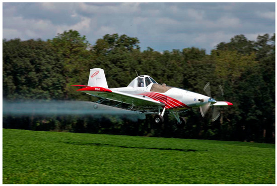
Figure 1.
A Thrush 510G turbine-powered aircraft spraying a crop over a field (Photo courtesy of Thrush Aircraft).
Under the fuselage on the T-boom, there were 6 nozzle positions, with spray nozzles placed in positions 3 and 6, referenced from port to starboard. On the left boom, nozzles were installed in the following positions (referenced from inboard to outboard): 1, 3, 5, 8, 10, 12, 14, 17, 19, 21, 23, 25, 27, 29, and 31. On the right boom, nozzles were placed in the following positions: 1, 3, 4, 5, 6, 8, 10, 12, 14, 16, 18, 20, 22, 24, 26, 28, and 31, for a total of 34 nozzles (CP-11TT, Transland, LLC., Wichita Falls, TX, USA). They were installed with 4012 tips, oriented 30° down and back, and operated at 324 kPa (Figure 2). The 4012 nozzle designation means that the tip had a 40° flat fan spray with a standard flow rate of 1.2 gpm (4.54 L/m) at 40 psi per nozzle (276 kPa). The aircraft was flown at 257 km/h with a boom height of 3 m.
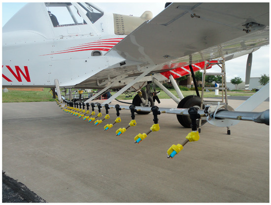
Figure 2.
Nozzle set up in the aircraft.
With a 20 m swath, this yielded an overall application rate of 20 L/ha. Based on the USDA-ARS Spray Quality Models [28], this resulted in a target volumetric median diameter (VMD, Dv0.5) of 203 µm and a droplet spectra classification of “Fine”. This is also in conformity with the ASABE S572.2 standard [29], Droplet Size Classification, to measure and interpret spray quality tips developed by the American Society of Agricultural and Biological Engineers. The Dv0.5, µm is the spray droplet diameter where 50% of the spray volume is contained in droplets smaller than this value and is commonly known as the volume median diameter (VMD).
2.1. Vortex Generators
One-hundred-and-four vortex generators (Micro Aerodynamics, Inc., Anacortes, WA, USA) were temporarily affixed full span just aft of the leading edge of the wings of a Thrush 510G agricultural aircraft by the manufacturer using silver foil tape. The VGs were temporarily installed prior to the VG treatment and then quickly removed prior to the No VG treatment so that meteorological conditions would remain consistent between treatments. The Micro Vortex Generators were manufactured under a FAA PMA from aircraft-grade 6063-T6 aluminum, alodined to military specifications (Figure 3)
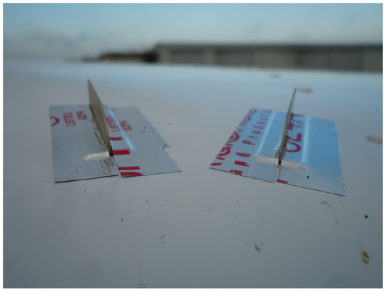
Figure 3.
Vortex generators installed on the leading edge of a Thrush aircraft.
2.2. Drift Study Setup
The target VMD of the spray applications was 200 µm. To achieve this target droplet size, nozzles were set up using the revised USDA-ARS Spray Quality Models [28]. The in-swath deposition and downwind movement of spray droplets were evaluated using the 1, 3, 6, 8-pyrenetetrasulfonic acid tetrasodium salt, PTSA dye (Spectra Colors Corp., Kearny, NJ, USA) as a tracer mixed with 757 L of water and R-11 surfactant (0.25% v/v). The spray solution was applied at 24.7 g/ha while the aircraft flew orthogonal to the prevailing wind with the sampling lines parallel to the prevailing wind (Figure 4). Three parallel sampling lines (A, B, and C), each 5 m apart, were established in the study area for measuring ground deposition. The downwind edge of the spray swath was designated as “0” distance. Negative distances represented the distance upwind of the downwind edge of the spray swath and positive distances represented downwind distances. In-swath sampling was conducted using 6 Mylar cards per sampling line placed on 929 cm2 wooden boards at distances of −25, −20, −15, −10, −5, and 0 m (Figure 5). Downwind spray deposition was measured using 6 additional Mylar cards per line placed at distances of 1, 2, 5, 10, 20, and 50 m.
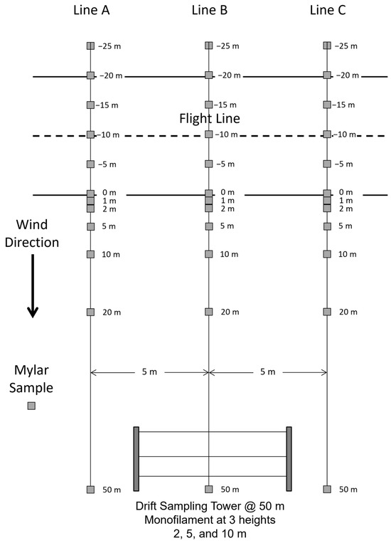
Figure 4.
Spray lines (A, B and C) showing in-swath and downwind sampling locations using Mylar cards and monofilament lines. The solid lines represent the upwind and downwind edges of the aircraft swath.
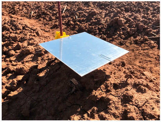
Figure 5.
Photograph of a Mylar plate placed in position in the field by affixing onto a metal rod for sampling spray deposition.
Deposition of the airborne component of the spray (i.e., drift) was measured by placing two drift towers 50 m from the downwind edge of the spray swath. Monofilament lines were horizontally suspended on the drift towers at 2, 5, and 10 m height. The drift towers were held in position using specially built stands that supported 10 m poles, which were rotated vertically up into place before each spray application. Table 1 describes the wind speed and direction recorded at 2 and 10 m monofilament heights during the test periods. Temperature and relative humidity averaged 27.4 °C and 32%, respectively, during the test period and were obtained from the Texas A&M University Farm Mesonet Site.

Table 1.
Wind velocity by treatment and replication.
2.3. Processing of Deposition Samples
Approximately 90 s after application, Mylar cards and monofilament lines were individually picked up and placed in plastic bags, stored in an ice chest, and transported to the laboratory for analysis. Ethanol (30 mL) was pipetted into each bag, the bags were thoroughly agitated, and 6 mL of the effluent was poured into a cuvette. The cuvettes were then placed into a spectrofluorophotometer (Shimadzu, Model RF5000U, Kyoto, Japan) with an excitation wavelength of 423 nm and an emission wavelength of 489 nm. To make comparisons between treatments, the fluorometric readings were converted to percent response. The highest fluorometric response within the 5/10/H sensitivity range of the samples was defined as 100% response. All other samples were referenced to this value. The spray pattern was analyzed using a fluorometric tracer method which equates fluorescence to dye concentrations. The fluorescence of processed samples was compared with the fluorescence from a set of reference samples with known dye concentrations, thus facilitating the calculation of the actual amount of dye present in the samples [30].
2.4. Data Analysis
Deposition data expressed as percent fluorometric response were analyzed using the PROC MIXED procedure with wind speed as a covariate [31]. Wind speed at 2 m height was used as a covariate in the analysis. An assessment of normality where the variance is independent of the mean is a prerequisite for conducting parametric analysis of the data. The PROC Univariate analysis of the fluorometric response from monofilament and Mylar samples indicated that the data significantly deviated from the normal distribution (Shapiro–Wilk statistic (W) = 0.88; p < 0.0001). The W is the goodness-of-fit statistic and p is the probability value testing the Ho that the data was from a normal distribution. Arcsine transformation, alias the angular transformation, was proposed for approximating the percentage responses to the normally distributed variates [32,33,34]. However, the monofilament data were analyzed without transformation because the data, when coded in proportions, were well within the 0.3 to 0.7 range for which no transformation was recommended [35,36]. However, Mylar data with proportions ranging from zero to unity were transformed to arcsine√ y, where y was the calculated percent fluorometric response. Each treatment was replicated five times and the replication was treated as a random component in the model. The DDFM = Kenward–Roger in the model statement was used to approximate denominator degrees of freedom. TRT×height and TRT×distance interactions relative to deposition on monofilament lines and Mylar cards, respectively, were partitioned using the SLICE statement. For example, SLICE = height causes a separate F-statistic to be computed for TRT effect at each height. ANCOVA analysis was conducted to test the null hypothesis that the regression lines and the intercepts were parallel, relative to deposition on monofilament lines as a function of wind speed. Graphical displays of the results were constructed using JMP®, Version 12 software [37].
3. Results and Discussion
3.1. Monofilament Lines
One objective of the study was to determine the effect of VGs on off-target spray drift. Drift deposits on monofilament lines positioned at 2, 5, and 10 m heights above ground were numerically higher in the No VG treatment compared to the VG treatment and resulted in a significant difference in drift deposits between the two treatments (F = 7.24; df = 1, 18.4; p > 0.01). Table 2 presents SLICE statements relative to deposition on each of three monofilament lines. Overall, mean percent drift deposits (±standard deviation) on monofilament lines in VG and No VG treatments were 25.32 ± 21.7% and 38.66 ± 22.9%, respectively. Deposition on monofilament lines at 2, 5, and 10 m did not vary significantly between heights (F = 2.39; df = 2, 17.3; p > 0.12). There also were no significant interactions relative to deposition on monofilament lines between treatments (F = 0.06; df = 2, 17.3; p > 0.94), which indicated that the deposition was independent of treatment. Wind speed significantly influenced deposition on monofilament lines in both VG and No VG treatments (F = 5.84; df = 1, 18.9; p > 0.03). Figure 6 shows a scatter plot of the deposits on monofilament lines vis-à-vis wind speed. Drift deposits were significantly less in the VG treatment. The reason for this is not fully understood but may be related to the boundary layer remaining intact as the airstream passes over the top of the wing and interacts with the VGs, creating small vortices that adhere to the upper surface of the wing. These vortices stay in close proximity to the top wing surface and emerge at the trailing edge of the wing with a downward flow trajectory. It is hypothesized that this downward flow trajectory interfaces with the spray plume to move the spray droplets down towards the ground (and intended target) rather than getting caught up in uncontrolled vortices generated without VGs, thus mitigating spray drift. More research is warranted to help understand how VGs reduce drift. The regression equation for the VG treatment is: Y = 43.13X − 85.83, where Y is the percent fluorometric response and X is the wind speed (m/s). The regression equation for the No VG treatment is: Y = 41.67X − 62.62. When comparing the slope coefficients of the VG and No VG treatments for homogeneity, the slopes are parallel (F = 0.00; df = 1, 26; p > 0.96), which demonstrates that the movement of driftable spray particles, once airborne, was comparable in both VG and No VG treatments, relative to wind speed. However, the test for homogeneity for the null hypothesis that the intercepts of the regression lines with a common slope are the same showed that there were indeed significant differences between the y-intercepts (F= 7.41; df = 1, 27; p > 0.01). The y-intercepts may be interpreted as the amount of spray vulnerable to drift. Because the regression lines were parallel, the difference in the least square means was equal to the difference in y-intercepts (least square means for the VG and No VG treatments were 22.34 and 41.64, respectively). These data suggest that there were nearly twice as many drift deposits in the No VG treatment than in the VG treatment.

Table 2.
Statistical analysis of the effect of vortex generators on drift deposits on monofilament lines. Means are percent fluorometric response (± standard deviation) and are a measure of drift aloft, 50 m downwind of the spray swath.
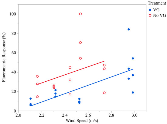
Figure 6.
Mean drift deposits on monofilament lines at varying wind speed (m/s). Deposition values for the different heights were pooled since no statistical difference between heights was established.
3.2. Mylar Cards
Deposition on Mylar cards placed at different distances downwind of the flight line of the aircraft varied significantly between treatments (F = 98.41; df = 11, 331; p < 0.0001). Moreover, interaction in deposition between treatments and the distance varied (F = 5.15; df = 11, 331; p < 0.0001). In-swath and downwind deposition on Mylar cards for the VG and No VG treatments are presented in Table 3. From the −25 m data, it can be seen that neither of the treatments caused spray deposits to move upwind. In fact, there were also no deposits for either treatment at −20 m, indicating a healthy crosswind. Downwind deposition for the VGs reached a peak on the downwind edge of the swath at 0 m and thereafter consistently decreased downwind. However, without VGs, downwind deposits reached a maximum at 5 m downwind and then continued to decrease thereafter. Significant differences in deposition between VG and No VG treatments occurred at in-swath locations, −15, 5, and 0 m, as well as at downwind locations from the edge of the swath at 5, 10, and 20 m. The No VG treatment had significantly greater deposits at each of these downwind locations compared to the VG treatment. VGs resulted in a 31.3% reduction in downwind deposits at 5 m, 53.6% reduction at 10 m downwind, and 61.0% reduction in downwind deposits at 20 m downwind. Figure 7 shows an overall in-swath and downwind deposition pattern in the VG and No VG treatments and indicates that the downwind deposition in the No VG treatment was symmetrically broader, suggesting greater downwind deposition compared to the VG treatment. These data show that more spray deposits remained within the swath when the VGs were installed and resulted in less downwind movement of the spray. This could be due to the vortex generators “bleeding off” some of the energy that would have otherwise gone towards the formation of wing-tip vortices. Some of this energy may instead be directing the spray plume back and down rather than out to the wing tips and up. Additional investigation will be needed to verify this hypothesis.

Table 3.
Statistical analysis of the effect of vortex generators on upwind, in-swath, and downwind deposits onto Mylar cards. Means are percent fluorometric response (±standard deviation) and are a measure of spray movement and deposition at various indicated distances downwind.
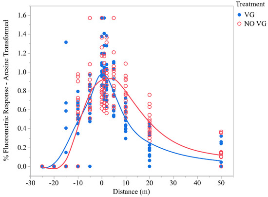
Figure 7.
In-swath and downwind deposition on Mylar cards averaged over 5 replications.
Wind speed did not significantly influence deposition on Mylar cards at ground level between treatments (F = 0.54; df = 1, 41.7; p > 0.46). This is expected as the horizontal wind (surface wind) decreases towards zero near the ground, resulting in a wind speed profile that is logarithmic with height in the surface layer [38].
Figure 8 shows the variability in deposition between VG and No VG treatments in each of the five replications. Except for Rep 3, fewer downwind deposits of dye occurred in the VG treatment compared to the No VG treatment in all other Reps. This shows that the VGs consistently reduced the number of driftable fines transported aloft. Instead, they appear to cause these fines to deposit closer to the swath of the aircraft. Although the results reported here are applicable to VGs manufactured by Micro Aerodynamics and Thrush aircraft, further studies on drift deposits, relative to other airframes and commercially available prototype VGs, are warranted.
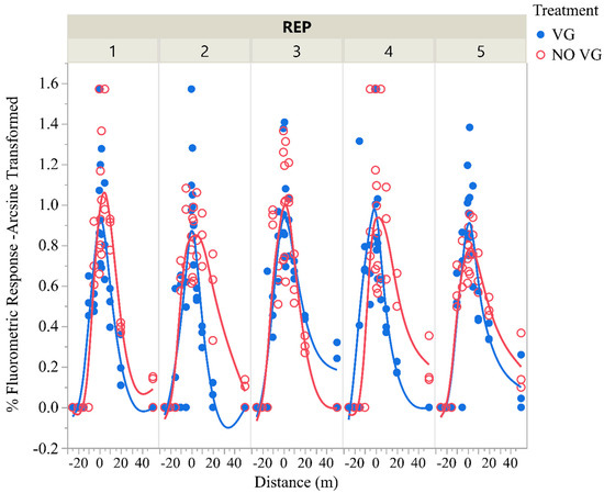
Figure 8.
In-swath and downwind deposition (arcsine transformed) of fluorescent dye on Mylar cards in each of 5 replications.
4. Conclusions
The development of new aerial application technologies is essential to protect croplands from off-target drift from agricultural spray applications. Aerodynamic devices, known as vortex generators (VGs), are commercially available for use in the aviation industry and are primarily used to increase pilot control of aircraft. Researchers have conducted studies using these devices primarily in the wind tunnel and have demonstrated that they help reduce boundary layer separation and drag coefficient, concomitantly helping to improve the performance of an aircraft. However, no studies exist describing spray deposition and drift when an agricultural aircraft is fitted with VGs. In this study, we sought to determine whether VGs could improve spray deposition and mitigate off-target drift when an agricultural aircraft conducts pest control activities in farm lands. Test results indicate that airborne deposits were significantly less in the VG treatment compared to No VG treatment and that there were nearly twice as much spray deposits in the No VG compared to No VG treatment. Moreover, ground deposit data show that more spray deposits remained within the swath when the VGs were installed and resulted in less downwind movement of the spray. The reason for the difference in spray deposition between VG and No VG treatment is not fully understood, but it is likely that the boundary layer may remain intact as the airstream passes over the top of the wing and interacts with the VGs, creating small vortices that adhere to the upper surface of the wing. These vortices stay in close proximity to the top wing surface and emerge at the trailing edge of the wing with a downward flow trajectory. It is probable that this downward flow trajectory interfaces with the spray plume to move the spray droplets downwind rather than getting caught up in uncontrolled vortices generated without VGs, thus mitigating spray drift. This study was conducted with VGs from a specific manufacturer and installed on a specific agricultural aircraft and hence may not be representative of other VGs on the market. Additional replicated studies using other airframes and commercially available VGs are warranted to better understand the effect of VGs on spray droplet trajectories, spray deposition and drift mitigation.
Author Contributions
Conceptualization, D.E.M.; methodology, D.E.M. and M.A.L.; formal analysis, M.A.L.; data curation, D.E.M. and M.A.L.; writing—review and editing, M.A.L. and D.E.M. All authors have read and agreed to the published version of the manuscript.
Funding
This research received no external funding.
Data Availability Statement
The data may be provided to anyone who is interested in the study results.
Acknowledgments
The authors would like to thank Thrush Aircraft, Inc., for use of the airplane and pilot for this study, Chief Test Pilot Jody Bays for his excellent piloting skills, Anni Brogan for providing and installing the vortex generators, Andy Scarmardo for use of his cotton field and members of the USDA-ARS Aerial Application Technology Research Team for assisting with the field work and data collection.
Conflicts of Interest
The authors declare no conflicts of interest. The Thrush Aircraft Inc. had no role in the design of the study; in the collection, analyses, or interpretation of data; in the writing of the manuscript; or in the decision to publish the results. The use of trade, firm, or corporation names in this publication is for the information and convenience of the reader. Such use does not constitute an official endorsement or approval by the United States Department of Agriculture or the Agri-cultural Research Service of any product or service to the exclusion of others that may be suitable.
References
- Teske, M.E.; Thistle, H.W.; Eav, B. New ways to predict aerial spray deposition and drift. J. For. 1998, 96, 25–31. [Google Scholar] [CrossRef]
- Klein, R.; Golus, J.; Cox, A.; Alexander, L.; Carpenter, P.; Cooper, S.; Glass, C.; Gummer Andersen, P.; Magri, B.; Robinson, T. Spray droplet size and how it is affected by pesticide formulation, concentrations, carriers, nozzle tips, pressure and additives. In Proceedings of the International Advances in Pesticide Application, Robinson College, Cambridge, UK, 9–11 January 2008; Association of Applied Biologists: Wellesbourne, UK, 2008; pp. 231–237. [Google Scholar]
- Van den Berg, F.; Kubiak, R.; Benjey, W.; Majewski, M.; Yates, S.; Reeves, G.; Smelt, J.; Van der Linden, A.M.A. Emission of Pesticides into the Air. Water Soil Air Pollut. 1999, 115, 195–218. [Google Scholar] [CrossRef]
- Salyani, M.; Cromwell, R.P. Drift losses from citrus spray applications. In Proceedings of the Florida State Horticultural Society, Fort Lauderdale, FL, USA, 1993; pp. 13–18. [Google Scholar]
- Yates, W.E.; Akesson, N.B.; Cowden, R.E. Criteria for minimizing drift residues on crops downwind from aerial applications. Trans. ASAE 1974, 17, 627–632. [Google Scholar] [CrossRef]
- Threadgill, E.; Smith, D. Effects of physical and meteorological parameters on the drift of controlled-size droplets. Trans. ASAE 1975, 18, 51–56. [Google Scholar]
- Hewitt, A.J. Developments in international harmonization of pesticide drift management. Phytoparasitica 2001, 29, 93–96. [Google Scholar] [CrossRef]
- Caldwell, D.M. Quantification of Spray Drift from Aerial Applications of Pesticide. Ph.D. Thesis, University of Saskatchewan, Saskatoon, SK, Canada, 2006. [Google Scholar]
- Reed, W.H. An Analytical Study of the Effect of Airplane Wake on the Lateral Dispersion of Aerial Sprays; Technical Note; National Advisory Committee for Aeronautics: Washington, DC, USA, 1953. [Google Scholar]
- Trayford, R.; Welch, L. Aerial spraying: A simulation of factors influencing the distribution and recovery of liquid droplets. J. Agric. Eng. Res. 1977, 22, 183–196. [Google Scholar] [CrossRef]
- Parkin, C.; Wheeler, P. Influence of spray induced vortices on the movement of drops in wind tunnels. J. Agric. Eng. Res. 1996, 63, 35–44. [Google Scholar] [CrossRef]
- Hewitt, A.J.; Johnson, D.R.; Fish, J.D.; Hermansky, C.G.; Valcore, D.L. Development of the spray drift task force database for aerial applications. Environ. Toxicol. Chem. 2002, 21, 648–658. [Google Scholar] [CrossRef] [PubMed]
- Parkin, C.; Spillman, J. The use of wing-tip sails on a spraying aircraft to reduce the amount of material carried off-target by a crosswind. J. Agric. Eng. Res. 1980, 25, 65–74. [Google Scholar] [CrossRef]
- Hoffmann, W. Influence of aircraft wingtip modifications on spray deposition and movement. In Influence of Aircraft Wingtip Modifications on Spray Deposition and Movement; American Society of Agricultural Engineers: Milwaukee, WI, USA, 2000; pp. 1–14. [Google Scholar]
- Hoffmann, W.; Tom, H.H. Effects of lowering spray boom in flight on swath width and drift. Appl. Eng. 2000, 16, 217–220. [Google Scholar] [CrossRef]
- Ryan, S.D.; Gerber, A.G.; Holloway, A.G.L. A computational study on spray dispersal in the wake of an aircraft. Trans. ASABE 2013, 56, 847–868. [Google Scholar]
- King, J.; Xue, X. A fast analysis of pesticide spray dispersion by an agricultural aircraft very near the ground. Agriculture 2022, 12, 433. [Google Scholar] [CrossRef]
- Borchers, I.; Drobietz, R.; Gruenewald, M.; Mau, K.; Reichenberger, J. Noise Reducing Vortex Generators on Aircraft Wing Control Surfaces. U.S. Patent 6,491,262 B2, 10 December 2002. [Google Scholar]
- Brüderlin, M.; Zimmer, M.; Hosters, N.; Behr, M. Numerical simulation of vortex generators on a winglet control surface. Aerosp. Sci. Technol. 2017, 71, 651–660. [Google Scholar] [CrossRef]
- Zhdanov, O.; Orlianskyi, V. Check for updates Researching Influence of Vortex Generators on Aircraft Aerodynamic Characteristics. In Proceedings of the 2nd International Workshop on Advances in Civil Aviation Systems Development; Springer Nature: Kyiv, Ukraine, 2024; pp. 410–422. [Google Scholar]
- Aeronautical Testing Service. Aeronautical Testing Service, Inc. 1999. Available online: https://www.aerotestsvc.com/ (accessed on 22 January 2024).
- Micro Vortex Generators for Single and Twin Engine Aircraft. Micro Aero Dynamics Inc. Available online: https://microaero.com/ (accessed on 9 January 2024).
- Tebbiche, H.; Boutoudj, M. Aerodynamic drag reduction by turbulent flow control with vortex generators. In Proceedings of the 5th International Symposium on Aircraft Materials, Marrakech, Morocco, 23–26 April 2014. [Google Scholar]
- Vignesh, V.; Emani, S.; Guven, U.; Velidi, G.; Yadav, R. Numerical Simulation of Aerodynamic Lift of a Clark Y Airfoil with Vortex Generators. In Proceedings of the International Conference on Modelling, Optimisation and Computing, Roorkee, India, 5 December 2011; pp. 1–5. [Google Scholar]
- Hansen, M.O.L.; Velte, C.M.; Øye, S.; Hansen, R.; Sørensen, N.N.; Madsen, J.; Mikkelsen, R. Aerodynamically shaped vortex generators. Wind. Energy 2016, 19, 563–567. [Google Scholar] [CrossRef]
- Lin, J. Control of turbulent boundary-layer separation using micro-vortex generators. In Proceedings of the 30th Fluid Dynamics Conference, Norfolk, VA, USA, 20 June–1 July 1999; p. 3404. [Google Scholar]
- Methal, Z.; Talib, A.S.A.; Bakar, M.S.A.; Rahman, M.R.A.; Sulaiman, M.S.; Saad, M.R. Improving the Aerodynamic Performance of WIG Aircraft with a Micro-Vortex Generator (MVG) in Low-Speed Condition. Aerospace 2023, 10, 617. [Google Scholar] [CrossRef]
- Fritz, B.; Hoffmann, W. Update to the USDA-ARS Fixed-Wing Spray Nozzle Models. Trans. ASABE 2015, 58, 281–295. [Google Scholar]
- ASAE S572.2; Spray Nozzle Classification by Droplet Spectra. ASABE: St. Joseph, MI, USA, 2020.
- Fritz, B.; Hoffmann, W.; Jank, P. A fluorescent tracer method for evaluating spray transport and fate of field and laboratory spray applications. J. ASTM Int. 2011, 8, 1–9. [Google Scholar]
- SAS. SAS Version 9.4; SAS Institute Inc.: Cary, NC, USA, 2012. [Google Scholar]
- Snedecor, G.W.; Cochran, W.G. Statistical Methods, 6th ed.; The Iowa State University Press: Ames, IA, USA, 1967; p. 593. [Google Scholar]
- Ott, L.R. An Introduction to Statistical Methods and Data Analysis; Duxbury Press: Belmont, CA, USA, 1993. [Google Scholar]
- Sokal, R.R.; Rohlf, R.R. Biometry—The Principles and Practice of Statistics in Biological Research; W. H. Freeman and Company: New York, NY, USA, 1969. [Google Scholar]
- Warton, D.I.; Hui, F.K.C. The arcsine is asinine: The analysis of proportions in ecology. Ecology 2011, 92, 3–10. [Google Scholar] [CrossRef] [PubMed]
- LeRoux, E.J.; Reimer, C. Variation between samples of immature stages, and of mortalities from some factors, of the eye-spotted bud moth, Spilonota ocellana (D. & S.) (Lepidoptera: Olethreutidae), and the Pistol casebearer, Coleophora serratella (L.) (Lepidoptera: Coleophoridae), on Apple in Quebec. Can. Entomol. 1959, 91, 428–449. [Google Scholar]
- SAS. JMP Version 14; SAS Institute: Cary, NC, USA, 2018. [Google Scholar]
- Stull, R.B. An Introduction to Boundary Layer Meteorology; Springer Science and Business Media: Berlin/Heidelberg, Germany, 1988. [Google Scholar]
Disclaimer/Publisher’s Note: The statements, opinions and data contained in all publications are solely those of the individual author(s) and contributor(s) and not of MDPI and/or the editor(s). MDPI and/or the editor(s) disclaim responsibility for any injury to people or property resulting from any ideas, methods, instructions or products referred to in the content. |
© 2024 by the authors. Licensee MDPI, Basel, Switzerland. This article is an open access article distributed under the terms and conditions of the Creative Commons Attribution (CC BY) license (https://creativecommons.org/licenses/by/4.0/).