Article

Blockchain-Based Malicious Behaviour Management Scheme for Smart Grids

1
Department of Computer Science and Information Technology, La Trobe University, Melbourne 3086, Australia
2
Faculty of Information Technology, Monash University, Melbourne 3800, Australia
*
Author to whom correspondence should be addressed.
Smart Cities 2023, 6(5), 3005-3031; https://doi.org/10.3390/smartcities6050135
Submission received: 15 September 2023 / Revised: 16 October 2023 / Accepted: 19 October 2023 / Published: 23 October 2023

Abstract

:
The smart grid optimises energy transmission efficiency and provides practical solutions for energy saving and life convenience. Along with a decentralised, transparent and fair trading model, the smart grid attracts many users to participate. In recent years, many researchers have contributed to the development of smart grids in terms of network and information security so that the security, reliability and stability of smart grid systems can be guaranteed. However, our investigation reveals various malicious behaviours during smart grid transactions and operations, such as electricity theft, erroneous data injection, and distributed denial of service (DDoS). These malicious behaviours threaten the interests of honest suppliers and consumers. While the existing literature has employed machine learning and other methods to detect and defend against malicious behaviour, these defence mechanisms do not impose any penalties on the attackers. This paper proposes a management scheme that can handle different types of malicious behaviour in the smart grid. The scheme uses a consortium blockchain combined with the best–worst multi-criteria decision method (BWM) to accurately quantify and manage malicious behaviour. Smart contracts are used to implement a penalty mechanism that applies appropriate penalties to different malicious users. Through a detailed description of the proposed algorithm, logic model and data structure, we show the principles and workflow of this scheme for dealing with malicious behaviour. We analysed the system’s security attributes and tested the system’s performance. The results indicate that the system meets the security attributes of confidentiality and integrity. The performance results are similar to the benchmark results, demonstrating the feasibility and stability of the system.

1. Introduction

In recent years, the smart grid concept has been noticed by many researchers. It is an electricity network that integrates technologies, including advanced metering infrastructure (AMI), energy cyber–physical systems (CPSs), and microgrids [1]. Broadly, smart grids can balance the needs of any user (supplier and consumer) to provide sustainable, economic and secure electricity supply efficiently. The advantages of smart grids are eliminating the monopoly of conventional electricity suppliers and enabling decentralised control and communication of autonomous distribution networks [2,3]. At the same time, the diverse resources in the smart grid ensure the continuity of power supply through alternate and cooperative supply, which also helps to reduce transmission losses, stabilise power supply, and prevent mass blackouts.
As a security technology applied in the smart grid, blockchain was originally proposed as a decentralised data ledger by Nakamoto [4]. It is a ledger with distributed ownership that allows information to be shared transparently across the network. In the blockchain, data information, such as transaction information is encapsulated into blocks by a consensus mechanism, and each block includes a timestamp, random number and hash value, which makes the content of the block tamper-proof and immutable. With these features, blockchains are often used in smart grids to ensure data integrity, confidentiality and availability.
A comprehensive survey of blockchain applications in smart grids through our published papers [5] reveals that the majority of contributions to the adoption of blockchain technology focus on security and privacy issues in smart grids. In a smart grid environment, security and privacy issues can be largely solved by the blockchain’s inherent characteristics. For instance, Agung and Handayani [6] utilised Ethereum to manage transactions in the smart grid, where the POW consensus mechanism assures the integrity of the transactions. Khattak [7] created a smart grid power trading system that provides privacy for smart grid transactions by using smart contracts. Guan [8] classifies and tags users into several groups; each group uses a private blockchain to record its members’ data and uses pseudonyms instead of groups to conceal users’ identities and maintain the groups’ internal privacy.
However, through the descriptions in [9], trust is a complex concept, and there is no clear consensus on this in the scientific literature. The trust issues to be considered involve not only the objects of trust, such as user-to-user trust and user-to-system trust, but also need to be evaluated at different levels of trust (e.g., physical devices, network access, distributed networks, applications and interfaces). Malicious behaviour is one of the factors that break the trust between users in the smart grid; it is a threat to the stability and reliability of the system environment, the transaction process and the supply process. These threats affect honest users in the smart grid, leading to less motivated participation [10]. We reviewed the existing literature dealing with malicious behaviour.
Jianbin’s GridMonitoring [11] proposes an electricity usage monitoring system using a combination of sovereign blockchain and smart contracts to solve the problem of user distrust of electricity usage readings. The smart contract in the system implements access control to hold defaulters in transactions accountable and penalise them while also alerting honest users. Jennath in [12] proposes the use of Bayesian inference methods to estimate the trustworthiness of each decision node in a network based on event decisions. And blockchain is used as a tool to implement node authorisation, access control, and distributed storage. The proposed approach can curb the frequency of malicious behaviour reports by isolating bad users. In [13], a trust model that can detect untrustworthy nodes in the smart grid is proposed. The model uses a fuzzy logic trust model to protect the smart grid from cyberattacks and thus reduce the proportion of malicious nodes. In [14], Aparna proposes a data analysis scheme that can detect malicious behaviour in blockchain-based smart grid systems. The scheme prevents malicious data from being recorded as transaction data in the smart grid system by testing the integrity of the data in real time and classifying the users. She also proposes an incentive mechanism to obtain malicious activity at the user end.
Through our review, we found that blockchain technology alone is insufficient to adequately discipline and counter attackers who initiate malicious behaviour. The contributions highlighted in the survey aim to ensure the authenticity of system data by addressing data integrity issues, thereby enabling users to trust system behaviour and data flows, but do not remove the fear of malicious behaviour from users.
To address the impact of malicious behaviour of users in the smart grid on other users and to improve the confidence of honest users in the security of other users and the smart grid, we propose the user management network (UMN) scheme. The scheme is based on the best–worst multi-criteria decision method (BWM) [15] and Hyperledger Fabric blockchain technology [16], which quantify various types of malicious behaviours that may exist in the smart grid based on the level of impact. Since the quantified result values are measurable and comparable, various penalty levels can be applied to different malicious behaviours. Meanwhile, the system uses the Hyperledger Fabric architecture, which provides the following benefits when creating monitoring-driven penalties and maintaining the trustworthiness of the smart grid:
  • Authenticity: Hyperledger Fabric has a built-in public key infrastructure (Fabric CA [17]) and support for external PKI, supporting authentication and protecting data integrity. Each user and entity has a unique digital certificate and corresponding private key that verifies that the identity is legitimate, trustworthy, and has not been forged.
  • Tamper-proof: Once a user’s personal account information (identification and malicious behaviour) has been identified and published to the blockchain, it is permanently recorded and cannot be tampered with.
  • Traceability: All penalties imposed on malicious users in the network and any information updated into the ledger can be traced.
This study aims to reduce the frequency of malicious behaviour in the smart grid environment with the following main contributions.
  • We propose a consortium blockchain-based network management solution for malicious behaviour penalty that intends to limit the frequency of malicious behaviour by penalising attackers and reducing their propensity to attack. We detail the design process of the scheme, including the system design architecture, system actions, operation logic, data flow, and the relevant algorithms to implement the penalties.
  • We provide criteria and methods for the quantitative evaluation of various malicious behaviours based on BWM, as well as countermeasures to penalise attackers.
The remainder of this paper is organised as follows. Section 2 briefly describes why we focus on malicious behaviour issues and reviews the gaps in smart grids. In Section 3, the system design scheme is described in detail, including the proposed framework, the participating entities, the components that make up the system, and the data structure of the ledger. Section 4 presents the algorithms and criteria used to quantify malicious behaviour during the deployment and implementation phases of the scheme. Section 5 provides a detailed description of how the program works. In Section 6, we demonstrate the confidentiality and integrity of our plans by analysing the security properties. In the performance evaluation Section 7, we evaluate the throughput and latency of the system. In Section 8, we discuss the novelty of our scheme by comparing the existing literature. Section 9 and  Section 10 summarise the future work and make a conclusion, respectively.

2. Related Work

In a smart grid, electricity can be generated by conventional power plants and users using small-scale generation facilities (such as solar panels). With the involvement of these users, there is a two-way choice between suppliers and consumers [18]. The two-way choice aims to expand user choice and increase transaction flexibility. However, this also facilitates malicious behaviour. Goel [19] and Abolfazl [20] concluded that the harm caused by malicious behaviour in the grid (e.g., illegal theft of electrical energy) is irreparable. Electricity theft through meter bypass, meter tampering, and direct line hookups may lead to electrical system instability, overloading, or interruption of electricity supply. It damages devices, causes electrical problems and results in significant financial losses. Compared to conventional grids, smart grids connected to the internet with the addition of smart control modules and databases pose additional cyber and information security issues [21,22]. Gunduz [23] summarises the smart grid’s cybersecurity threats, including eavesdropping, sniffing, false data injection, masquerading, and jamming spoofing attacks. These attacks can compromise cybersecurity objectives (confidentiality, integrity, availability (CIA) [24]), leading to many serious consequences, such as customer information leakage or infrastructure damage.
Ref. [25] investigates the solutions to address the above malicious behaviours, including encryption, authentication, security protocols, security architectures, and other network countermeasures. These methods are all based on defence and resistance, which can effectively delay the attack or reduce the probability of success of the malicious behaviour, but they cannot fundamentally avoid or reduce the presence of attackers and the frequency of attacks. Attackers will try to come up with various ways to attack, and experts will need to invest time and resources to figure out how to respond. The best way to minimize or avoid malicious behaviour is to reduce the attacker’s willingness to attack and increase the cost of the attack. To achieve this goal, we need to detect and penalise malicious behaviour. The published research papers contribute many methods for detecting and monitoring different types of malicious behaviour. We reviewed this literature and formed Table 1. Based on the detection methods in Table 1, we can penalise malicious behaviours through accountability [26] or from a legal perspective [27,28].
The invention of blockchain offers new ideas for privacy and other security objectives, including availability, integrity and confidentiality. Decentralised distributed ledger, consensus mechanism and cryptography make the block content difficult to tamper with and achieve the purpose of protecting information security. Weerapanpisit et al. [37] use blockchain technology to maintain consistency and fault tolerance of reputation management systems between different nodes. Melo et al. [38] improve the measurement applications through blockchain, ensuring the integrity of distributed measurement systems. The above literature demonstrates the great potential of blockchain to address security issues in smart grids, IoT and distributed networks, proving blockchain’s anonymity, security and availability. After combining the best–worst multi-criteria decision method (BWM), we propose a consortium blockchain-based penalty mechanism for malicious behaviour handling. It provides a new approach to proactively intervene with malicious behaviours to reduce the frequency of malicious behaviours occurring.

3. Scheme Design

In this section, we describe a Hyperledger Fabric-based user management network scheme for managing and penalising users to reduce the frequency of malicious behaviour. The key concept is to use Hyperledger Fabric to ensure the secure and stable operation of the penalty system, while improving the network’s ability to scale for timely updates and customisation flexibly. A summary of the notations we used is provided in Table A1.

3.1. Design Overview

In order to maintain a fair and reliable trading environment for smart grids, we have developed a modular, decentralised user management network (UMN) based on the Hyperledger Fabric framework (Hyperledger Fabric is an open-source blockchain framework hosted by The Linux Foundation that can be used as the basis for developing applications or solutions with a modular architecture, and its modular and versatile design can address a wide range of industry use cases, including education [39], healthcare [40], access control [41,42], IoT [43], logistics [44], supply chain [45] and more), which implements management, monitoring, and penalty functions for users involved in the smart grid. The network is designed to focus on managing user behaviour and reducing the harm caused by malicious behaviour.
The developed model can be understood as an independently operating user behaviour management module attached to the smart grid. It works similarly to the security guards between users and the smart grid, isolating malicious attackers and protecting the smart grid from attacks. Before a user can access the smart grid, they need to be authenticated by the UMN. The user submits a registration request to the administrator that includes personal or organisational information (e.g., name or organisation name, address, meter number, etc. that helps to identify the user uniquely) and authentication documents (e.g., proof of identity, proof of address, driver’s license, and other official documents). The administrator verifies and issues an identity certificate for the user. The administrator role is usually filled by a staff member with access to official government databases or a program that can authenticate. When the user is successfully registered, their access permission ( A p ) in the ledger will be marked. The smart grid determines whether a user is allowed to enter it by checking the user’s ( A p ) . The deployed UMN will monitor user behaviour in the smart grid through monitoring nodes for transaction and non-transaction processes. When malicious behaviour is detected, the monitoring node will form a corresponding malicious behaviour report for the malicious user, which the chaincode will analyse in the UMN. The results obtained from the analysis are used as criteria for whether and how to penalise the user. The benefits of this approach include:
  • Blocking any unauthorised user from accessing the smart grid to avoid anonymous attackers,
  • Promptly addressing and penalising attackers,
  • Cutting off their access to reduce grid losses, and
  • Ensuring that each phase is done correctly and alleviating the concerns of honest users.

3.2. System Architecture and Components

Hyperledger Fabric is a scalable and modularly deployable architecture that upgrades the system architecture by inserting replacement modules as the system’s complexity grows. To achieve our aims, we customised the following network architecture model. The structure illustrated in Figure 1 contains four entities that interact with the network: Users ( U i ) , Admins ( A i ) , Monitoring ( M N i ) and Smart Grid ( S G ) , and three main components that make up the network: CA, Peer and Orderer.

3.2.1. Network Entities

i
Users ( U i ) :
U i is the various groups of clients who wish to participate in S G , including consumers and suppliers directly involved in the transaction and the staff who maintain the S G . U i interacts with the UMN (c) via the Software Development Kit (SDK) to send registration proposal containing real identity information I, receive penalty decisions, verify penalty results, and interacts with S G (g) to send entry requests.
ii
Admins ( A i ) :
A i exists in each organisation to provide registration services for U i . Using a CA client, A i registers certificates (i) for U i who have passed verification. By communicating with the UMN, A i can initialize U i account information into the ledger (d). A i are not allowed to access S G to participate in transactions directly and cannot interfere with the UMN system, but they can take on the role of observers, observing U i behaviour and feeding back to M N i .
iii
Monitoring Nodes ( M N i ) :
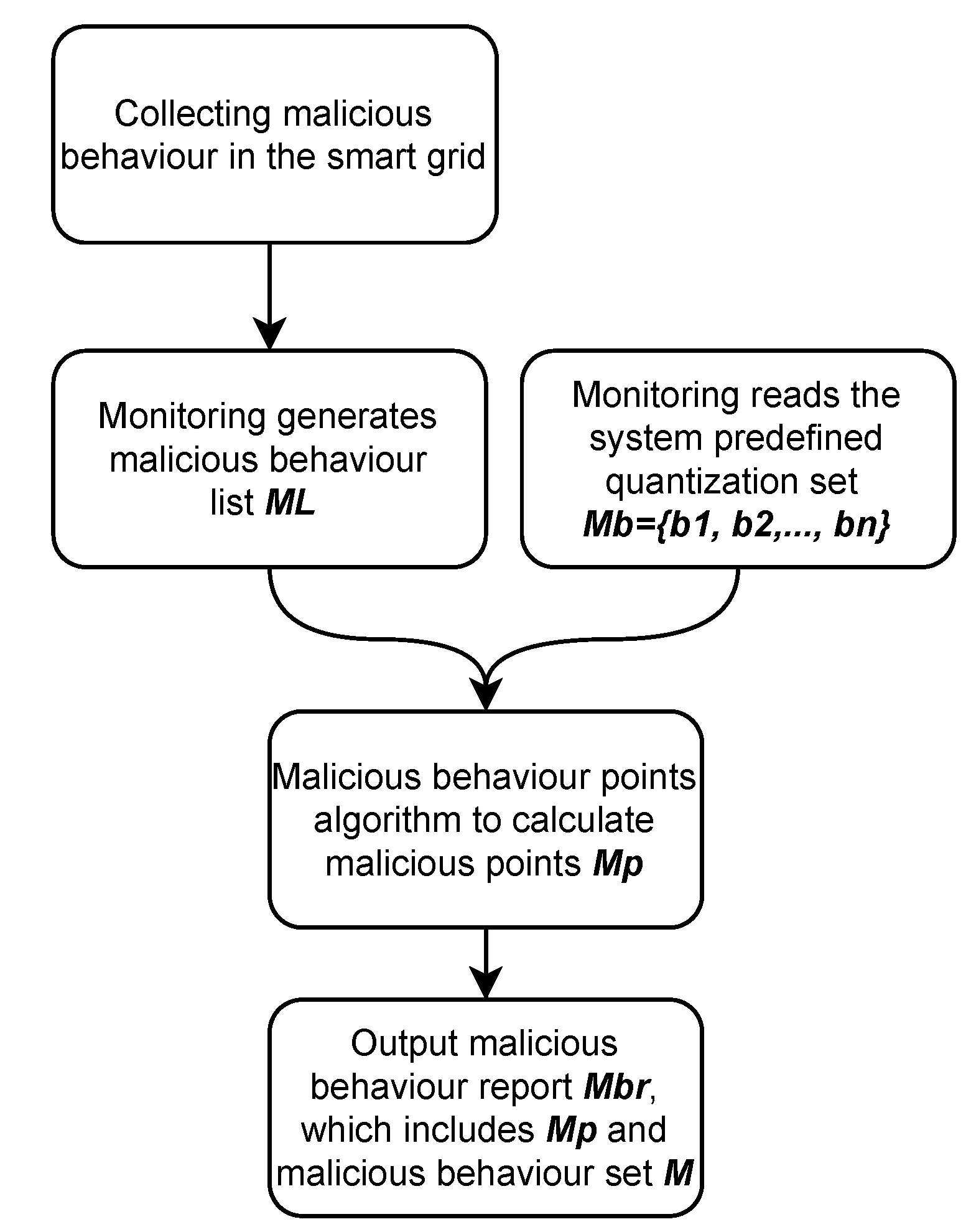
M N i is a cluster of various physical hardware devices such as Advanced Metering Infrastructure (AMI) deployed and set up to automatically perform monitoring on S G and have analysis and reporting capabilities. Among these features of M N i , the process of automatically monitoring and collecting information about malicious behaviours is complex and out of the scope of our research, so we set the following assumptions based on the support of existing research and focus on how to analyse and pre-process malicious behaviours and how to report them into UMN (f). M N i can detect the set M of all malicious behaviours imposed by a specific attacker in the smart grid (h) refer Table 1. For the collected set of malicious behaviours M, the M N i will first analyse it to generate the malicious behaviour list M L as shown in the Table 2, where the table includes the product of losses P i j for each malicious behaviour M i in the best weight ( w 1 * , w 2 * , w 3 * , , w n * ) (defined in Section 4.2.1) of different criteria and the number of times the behaviour recurs t. After generating M L , M N i will analyse and pre-process it using the steps in Section 4.2.2, and then output the user’s malicious behaviour report ( M b r ) including malicious points M p and malicious set M. The specific workflow is shown in Figure 2. The generated report M b r will be reported to the UMN network so that the penalty mechanism can be applied.
iv
Smart Grid ( S G ) :
S G is a separate, complete electricity service network for accessing and trading electricity. S G processes user requests for access to the Smart Grid Network (g) by interacting with the UMN and checking the user’s access rights attributes in the UMN world state (e). Meanwhile, S G is also responsible for collecting the penalty F p (defined in Section 4.4) and returning receipts.

3.2.2. Network Components

i
Certificate Authority (CA):
The Hyperledger Fabric contains the abstract concept of a Member Service Provider (MSP). It is based on a Public Key Infrastructure (PKI) that protects network entities, peers and orderers and maintains the network’s privacy and confidentiality. In the UMN, there are two types of CAs: the TLS CA, which protects the communication between organisations, nodes and processes. The other is the CA of each organisation, which issues certificates to the orderer nodes, peer nodes and network entities ( U i , A i , M N i , S G ) in their respective organisations so that they can verify each other’s identity. The CA structure of each organisation includes a CA server and CA client. The server is responsible for listening to permission requests from clients and performing operations such as registration, activation, renewal, and revocation. The client communicates with the server through the command line interface (CLI) to register identities and enrol the nodes to obtain certificate files.
ii
Peer:
Peer nodes have two roles in the UMN network. The first is to offer interaction for external entities to query the ledger (a-1) and execute the chaincode (smart contract). External entities can send chaincode invocation requests to the node, and the node can invoke the chaincode for pre-processing, endorsement and verification after receiving the requests. Peer is also responsible for operating the chaincode (a-2) as a carrier of the chaincode to offer a platform for the chaincode’s interaction with the network. The second role is to act as a commit and anchor node in the network to receive data blocks from the network and forward them to other nodes to synchronise, update and maintain all ledgers in the network (a-3).
Each peer node in the UMN network contains two elements, a separate copy of the ledger and a copy of the chaincode. The ledger consists of a world state and a blockchain. The world state is a database that stores the current state of the ledger, which records immutably any information changes made by smart contracts, intending to make the current value of the database state easily accessible. In contrast, the blockchain is a log of system information updates that records all changes to the world’s present state. The data structure of the blockchain is immutable and cannot be modified once written. We define the following data structure Table 3 of U i accounts that appear in the world state database and the blockchain.
In Table 3, where ID and UserName are proof to determine the user’s identity, AccessPermission is the basis used by the smart grid to determine if the user has access to the grid, MaliciousBehaviour is the malicious behaviour imposed by the user on the smart grid, MaliciousPoints is the criterion to determine if the user receives a penalty, FinesDeadlineAndFinesmap use the date as the keyword for a map to hold the amount of the penalty, for example [“01/02/2022 11:31:31”] = “$100”, TimePenalty end date is the date the advanced penalty (Defined in Section 4.1) ends, and TimeStamp is the time the ledger adds this data.
The chaincode is a component that manages and packages smart contracts. To implement the functionality of the UMN system, we have designed five smart contracts: User Registration Contract (URC), Malicious Behaviour Contract (MBC), Account Maintenance Contract (AMC), User Payment Contract (UPC) and account reset contract (ARC). Among them:
  • User Registration Contract (URC): URC will be initiated and deployed between A i to register new U i . The C r e a t e U s e r ( ) function is created and executed to initialise the user account ( U a ) , and its function will only accept proposals from A i . The contract will record additional information such as username, user id, access permission, timestamp and other relevant information.
  • Malicious Behaviour Contract (MBC): The MBC is designed to handle malicious behaviour reports M b r submitted by M N i . Based on the penalty rules in Section 4.1, the MBC will generate the penalty decision and update it to U a .
  • Account Maintenance Contract (AMC): The AMC is set up to monitor whether the user has completed the corresponding penalty. Once the penalty parameter in U a is non-empty, AMC will automatically deploy. It confirms whether further penalties are to be imposed on the U i by determining if the U i has paid the penalty F p on time during the primary penalty phase described in Section 4.1.
  • User Payment Contract (UPC): The role of the UPC is to verify that the U i has successfully paid the F p to S G . After the U i has paid the F p , he/she must submit an application to the UPC to verify the F p result. The UPC verifies the signatures of S G and U i in r e c p t ( U i ) submitted by the U i . For r e c p t ( U i ) that passes the verification, the penalty information recorded in it F i n e s D e a d l i n e A n d F i n e s m a p will be removed from the user’s U a in the world state database.
  • Reset Account Contract (ARC): ARC restores the legal status of user U a in the world state at the end of each level of penalty. Every change in the ledger will trigger the ARC, and it decides whether to update U a by examining the information in the ledger.
iii
Orderer:
The Hyperledger Fabric structure works in a way that defines the important role of the orderer in the network. To ensure that the proposals recorded in the ledger are correct and there are no forks, the orderer is required to order and distribute the proposals. The orderer uses a consensus algorithm to order the transactions for the endorsed proposals and packages them into blocks, and packaged blocks are then distributed to the submitting nodes in the network for validation against the endorsement policy [46]. The orderer is also responsible for maintaining the channel and implementing basic access control. The channel is the bridge for communication and exchange between organisations and is used to protect the privacy of credit value changes, while the orderer restricts who can read and write data and who can configure them.

4. Penalty Mechanism

The penalty mechanism in UMN is an important tool for quantifying and enforcing penalties. In this section, we first introduce the penalty settings and logic, followed by a detailed description of the penalties designed using BWM, including deployment settings, definitions, and algorithms.
BWM [15] is a method used to solve multi-criteria decision-making (MCDM) problems. In the MCDM problem, alternatives are evaluated and rated with quantitative scores based on several criteria and output a final ranking of the alternatives based on multiple criteria. According to BWM, the decision maker determines the best (e.g., most desirable and most important) and worst (e.g., least desirable and least important) criteria. These two criteria (best and worst) are then paired and compared with other criteria. A maximisation problem is then formulated and solved to determine the weights of the different criteria. The weights of the alternatives in terms of different criteria are obtained using the same process, and its final score is derived by aggregating the weights of different criteria and alternatives. These scores can then represent the position of this alternative in the overall choice and the importance percentage. According to Jafar’s statistical results, BWM outperforms in terms of the consistency ratio and other evaluation criteria (minimum violation, total deviation and consistency). Compared to conventional MCDM methods, the distinguishing characteristics of the BWM methodology are that it requires less comparable data and leads to more consistent comparisons, resulting in more accurate conclusions.

4.1. Penalty Strategies

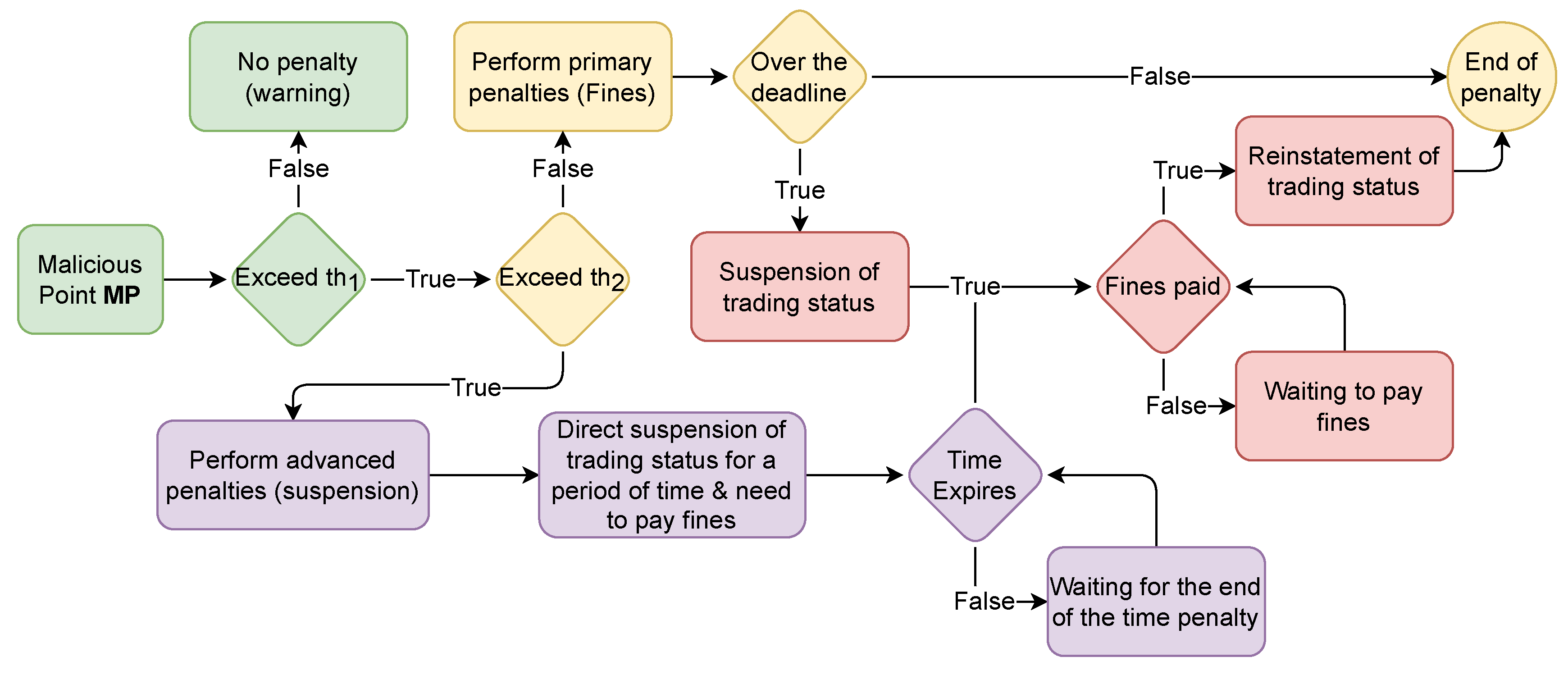
The penalty in the UMN is judged based on the user’s malicious behaviour points M p . Considering the means that can be applied to penalties in real situations, we set three levels of penalties. The first level is the warning level, which does not impose any penalty on the user but notifies and warns about the occurrence of malicious behaviour. The second level is the primary penalty (fines), where the user is required to pay a fine within a specified period, during which the user can still participate in the smart grid as normal. If the user fails to pay the fine by the deadline, the permission to access the smart grid will be suspended and not restored until the user has paid the fine. The third level is the advanced penalty (suspension). When triggered by the user, the permission to access the smart grid is immediately suspended and lasts for a while. During the period of the penalty, the user will also be required to pay a fine, and access will only be restored once both the time has expired and the fine has been paid. The specific penalty enforcement process is shown in Figure 3.

4.2. Malicious Behaviour Point Algorithm

The malicious behaviour point algorithm is designed for each organisation’s monitoring node to implement the monitored malicious behaviour and convert it into a quantifiable value, which will be added to the user’s account as a proxy for the severity of the malicious behaviour and will be used to determine the level of user malicious behaviour. The algorithm consists of two phases, the first of which exists in the deployment phase of the monitoring node and aims to generate a quantified set M b = { b 1 , b 2 , b 3 , , b n } of malicious behaviour unit conditions for the reference of the monitoring node, where b denotes the quantified value for a specific malicious behaviour unit condition, e.g., electricity stealing in the quantified value of the malicious behaviour of stealing 1 kWh of electricity is b j . The second stage exists in the real-time processing phase of the monitoring node, where the monitoring node calculates the set L p = { l 1 , l 2 , l 3 , , l n } of the damage caused by the malicious user, where l represents the product of the damage caused by malicious behaviour from the moment the behaviour occurs until the moment it is terminated. The monitoring node also invokes the set of doubling penalties for the user’s repeated mistakes R m = { r 1 , r 2 , r 3 , , r n } , where r represents the number of times each malicious behaviour occurs, corresponding to the doubling penalty factor. The final M p is calculated by combining L p and R m .

4.2.1. Deployment Phase

In order to obtain the set M b = { b 1 , b 2 , b 3 , …, b n }, we first need to obtain the criteria { c 1 , c 2 , c 3 , …, c n } used to quantify each malicious behaviour b j and the best weight ( w 1 * , w 2 * , w 3 * , …, w n * ) for criterion. The weights are calculated using the best–worst multi-criteria decision-making method (BWM) proposed by Jafar, described in the following steps.
Step 1: Identify a set of criteria that can be used to determine the impact of malicious behaviour in the smart grid { c 1 , c 2 , c 3 , …, c n }, e.g., {direct power loss ( c 1 ), direct monetary loss ( c 2 ), loss of time to repair the network ( c 3 ), loss of equipment ( c 4 ), loss of interest ( c 5 ),…, any effects that may be caused by any malicious behaviour ( c n )}
Step 2: Determine the criteria c W for the most severe impact and c M for the least severe impact, e.g., direct power loss ( c 1 ) can cause significant losses so c W = c 1 , interest loss c 5 does not jeopardize the operation of the whole grid so c M = c 5 .
Step 3: Use a number between 1 and 9 to determine the preference of the most severe influencing criterion over all other influencing criteria. The Worst-to-Others vector would be A W = ( a w 1 , a w 2 , a w 3 , …, a w n ), where a w j indicates the preference of the most severe criterion w over criterion j, and it is clear that a w w = 1 .
Step 4: Use a number between 1 and 9 to determine the preferences of all criteria relative to the least severe impact. The resulting Others-to-Minimal vector will be A M = ( a 1 m , a 2 m , a 3 m , …, a n m ) T , where a j m denotes the preference of criterion j for the least severe criterion m. It is clear that a m m = 1
Step 5: Find the optimal weights ( w 1 * , w 2 * , w 3 * , …, w n * ), where w j * indicates the optimal weight of the c j criterion where j = 1 , 2 , 3 , , n . The standard optimal weights are that for each pair w w / w j and w j / w m , we have w w / w j = a w j and w j / w m = a j m . To satisfy these conditions for all j, we should find a solution where the maximum absolute difference | w w w j a w j | and | w j w m a j m | is minimized for all j. Considering the non-negativity of the weights and the summation conditions yields, the following problem (1) results:
Min Max j w w w j a w j , w j w m a j m s . t . j = 1 n w j = 1 w j 0 ( j = 1 , 2 , 3 , , n )
The above problem (1) can be converted to the following problem (2):
Min ξ s . t . w w w j a w j ξ , j = 0 , 1 , 2 , , n w j w m a j m ξ , j = 0 , 1 , 2 , , n j = 1 n w j = 1 w j 0 , j = 1 , 2 , 3 , , n
Solving problem (2), the optimal weights ( w 1 * , w 2 * , w 3 * , …, w n * ) are obtained.
Next, after obtaining the optimal weights ( w 1 * , w 2 * , w 3 * , …, w n * ), they are used to score each possible malicious behaviour b in the network using a questionnaire that allows experts in the relevant field to score each malicious behaviour b j according to the malicious behaviour impact criterion { c 1 , c 2 , c 3 , …, c n }, and each impact c j according to the impact level from 0 to 10, with the scoring result being S. The set M b = { b 1 , b 2 , b 3 , …, b n } is then obtained by the following matrix calculation (3), where the value of each b j in M b is obtained by summing the multiplication of the scoring result S and the criteria weights w * :
M b = w 1 * w 2 * w 3 * w n * b 1 b 2 b 3 b n S 11 S 12 S 13 S 1 n S 21 S 22 S 23 S 2 n S 31 S 32 S 33 S 3 n S d 1 S d 2 S d 3 S d n b j = i = 1 n S ji · w i *

4.2.2. Real-Time Calculation Phase

Due to the possibility of multiple malicious behaviours occurring concurrently, the optimal weights ( w 1 * , w 2 * , w 3 * , …, w n * ) are used to calculate the product of losses over a certain duration using the same criteria as in the first phase. The only difference is that the number represented by the P is quantified by the actual number of behaviours that occurred for each behaviour instead of the number obtained by scoring (note that the different quantification criteria are balanced on the same units of quantity, e.g., electricity (per k W h ), time (per hours), and money (per dollar)). The product of the losses corresponding to each l j is calculated from the following matrix (4), and the set L p = { l 1 , l 2 , l 3 , …, l n } is obtained, where each l j is the sum of the products of the effects of all the different losses caused by a given action over time:
L p = w 1 * w 2 * w 3 * w n * l 1 l 2 l 3 l n P 11 P 12 P 13 P 1 n P 21 P 22 P 23 P 2 n P 31 P 32 P 33 P 3 n P d 1 P d 2 P d 3 P d n l j = i = 1 n P ji · w i *
When calculating the set L p , the set of factors R m = { r 1 , r 2 , r 3 , …, r n } used to double the penalty is also needed, where each r j denotes the factor of the number of times a particular individual behaviour is repeated. The computational equation is r = t t , where t is the number of times a particular behaviour is repeated.
After the monitoring node has calculated the set L p and R m , the final credit value M p is calculated by the following Equation (5):
M p = j = 1 n b j · l j · r j

4.3. Definition of Penalty Thresholds

The definition of the threshold value exists in the deployment phase and determines whether a user needs to be penalised. The primary penalty is triggered when the user’s account points accumulate over the threshold t h 1 , and the advanced penalty is triggered if the points reach t h 2 . The specific choice of threshold t h can be defined as follows.
After obtaining a quantitative control set M b = { b 1 , b 2 , b 3 , …, b n } of malicious behaviours for each organisation, we first sort the b j in the set M b in order from smallest to largest to form a sequence of sets M b n e w . Then we evaluate the malicious behaviours in the sequence by traversing from smallest to largest and select the first traversed behaviour that requires a primary penalty (as long as the behaviour must be penalised at the moment of occurrence) with its unit quantisation value b k as the threshold t h 1 . Similarly, t h 2 is the first traversed behaviour with zero tolerance that requires an advanced penalty.

4.4. Penalty Algorithms

From Section 4.1, our implementation requires determining a penalty amount and a penalty time. The calculation of the fine F p is based on a minimum fine amount F p m , which is determined by multiple admins and is set according to the amount of the fine that the user should pay after the threshold t h 1 behaviour unit time occurs, and the length of the deadline to pay the fine is also determined when setting the fine. After determining the F p m , the total amount of the fine F p to be paid when the malicious points exceed the threshold t h 1 is expressed as (6):
F p = User s current account total point t h 1 × F p m
Similarly, the suspension time T p defined by the advanced penalty is calculated according to the minimum penalty time T p m corresponding to the threshold t h 2 behaviour, which is expressed as (7):
T p = User s current account total point t h 2 × T p m

5. How UMN Works

According to the penalty mechanism in Section 4, our proposed UMN scheme is divided into three operational phases:
  • User registration, enrolment and login phase;
  • Monitoring and malicious behaviour handling phase;
  • Enforcing penalties, maintaining and resetting phase.
This section explains how the system works at each phase, its data structure and key algorithms.

5.1. User Registration, Enrolment and Login Phase

The user registration, enrolment and login phases are necessary for the U i to join the S G , and only those who pass this phase can access the S G . The entities involved in this phase include U i , A i and the S G .
In the registration part, A i is required to perform the following two steps. Step 1 is to verify the user’s real identity information I. Step 2 is to send a request to the CA server to register certificate U c a for U i . Specifically, U i sends a registration request r e q ( I ) to A i . After receiving r e q ( I ) , A i verifies I using methods such as database matching or two-factor authentication. When the authentication is passed, A i generates ( I D , P w ) for U i and sends r e g i s t e r ( I D , P w ) to the CA server, while A i sends a user initialisation proposal {“function”: “CreateUser”, “Args”:[“ID”, “UserName”]} to the endorsing peer node of UMN to invoke the URC.
Figure 4 shows URC (chaincode) execution steps in UMN. A i sends a proposal to the endorsing peer node. The peer node invokes URC to pre-execute the received proposal and returns the result to A i . When A i receives the number of endorsement results that meet the requirements of the endorsement policy, it packages and forwards them to the orderer node. The orderer node uses a consensus mechanism to order the received endorsements and generate blocks, which are then sent to the commit peer node. The committing peer node first validates these blocks and updates them to the ledger when they pass the validation. The successful initialisation of U a is shown in Table 3.
In the enrolment part, U i uses ( I D , P w ) to send e n r o l l ( ) to the CA server and obtain a certificate file U c a . The U c a file contains several important parts: cacerts, keystore, signcert and tlscacerts. The cacerts is a list of self-signed X.509 certificates representing the organisation’s trusted root CA. The keystore is the private key used to sign data. The signcert contains the CA-issued certificate representing the user’s identity, and the tlscacerts is similar to cacerts, but its role is to secure communication over the network.
In the user login part, S G responds to the U i login requests by verifying U c a and querying UMN to confirm access permission A p .
Moreover, it is worth noting the privacy issue of the identity of entities in UMN. In order to protect the privacy and anonymity of entities, our scheme should be able to restrict access to the true identity of any entity sending a proposal to the physical location or IP address of any entity and to associate any entity with the corresponding organisation. For this purpose, we use Identity Mixer [47] to provide privacy protection for the above issues. The Identity Mixer technology is a cryptographic protocol kit with an efficient zero-knowledge proof scheme that provides strong authentication and privacy protection. These include conducting transactions without explicitly identifying the trader (anonymity) and enabling a single identity to send multiple transactions without showing that they were sent by the same identity (unlinkability). Specifically, an entity’s secret key can correspond to multiple independent public keys simultaneously, allowing different public keys to be used for each proposal for different types of entities. Each public key can be converted into a valid zero-knowledge certificate that contains only some of the original certificate’s properties. The converted zero-knowledge certificate remains valid when verified against the issuer’s public key.

5.2. Monitoring and Malicious Behaviour Handling Phase

In the monitoring and malicious behaviour handling phase, the M N i monitors the S G , and the MBC handles and applies penalties to the monitoring results. In this phase, M N i invokes the MBC by sending M b r to the UMN, where M b r is obtained by pre-processing according to the steps in Section 4.2. MBC uses the pseudocode Algorithm 1 to handle malicious behaviour and update the results into the ledger.
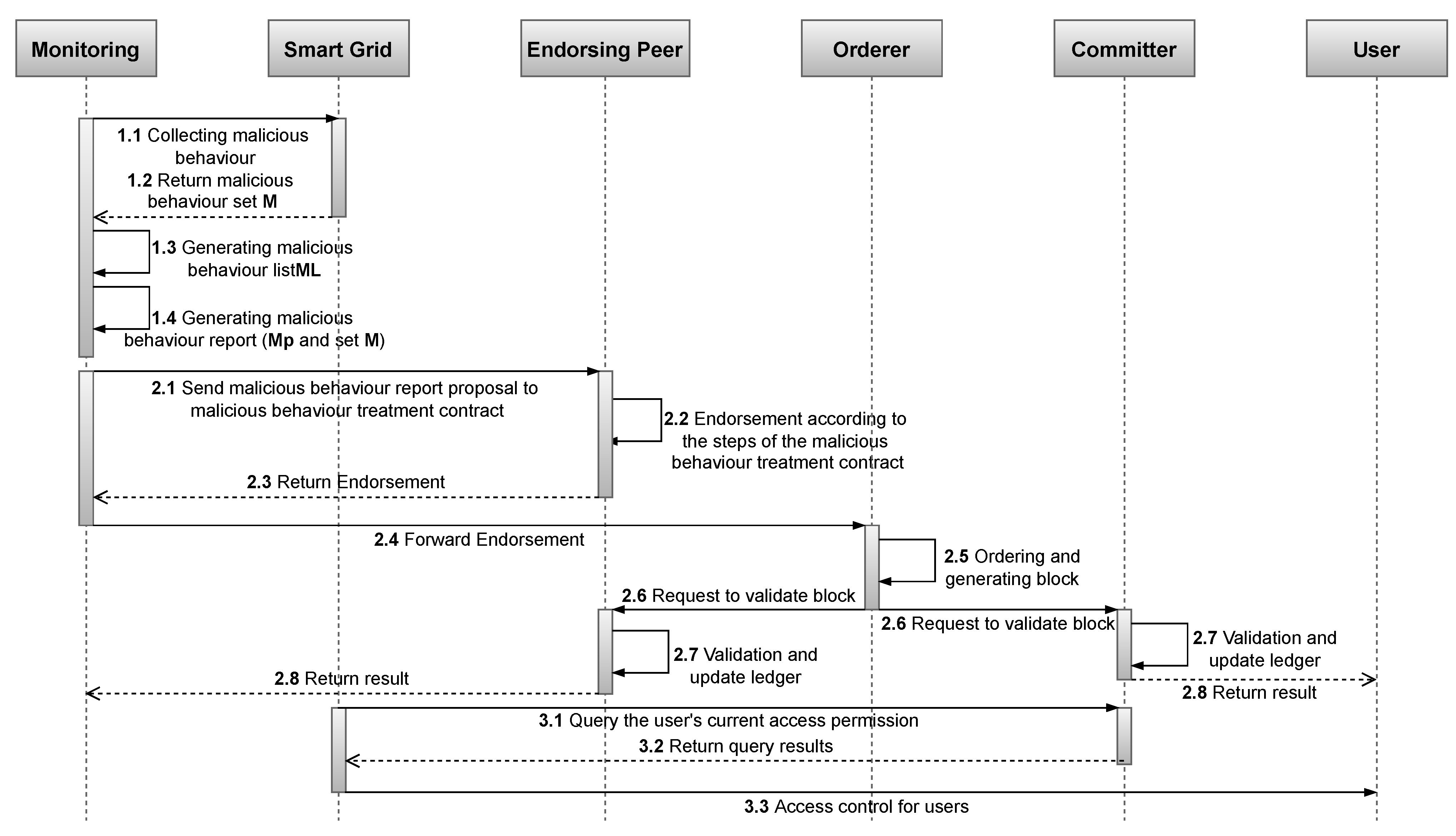
The data being executed in Algorithm 1 include AccessPermission; MaliciousBehaviour; MaliciousPoints; FinesDeadlineAndFines; TimePenalty; TimeStamp. MaliciousBehaviour and MaliciousPoints are submitted by M N i , AccessPermission; FinesDeadlineAndFines and TimePenalty are derived from the definitions and method operations set in Section 4.3 and Section 4.4. The sequence diagram in Figure 5 shows how the parts involved in monitoring penalties are connected and how penalties are created and recorded by showing the flow of transactions among M N i , S G and UMN.
  • Steps 1.1 and 1.2 are off-chain actions among M N i and S G , aiming to monitor and collect the set of malicious behaviours M in the S G . We use the contents of M as input to step 1.3 to drive the analysis module in the M N i .
  • Step 1.3 Match each malicious behaviour in M with the predefined malicious behaviour database in Section 4.2.1. The successfully matched M i are generated M L and input into step 1.4, while the unsuccessful matched M i is analysed and updated to the database by the expert group. Step 1.4 then performs further operations on the generated M L to generate M p .
  • Steps 2.1–2.4 are on-chain processes carried out by the MBC in a similar flow as Figure 4, where the input M p is compared with t h 1 and t h 2 to generate F p and T p .
  • Steps 3.1 to 3.3 are taken by the S G . For a U i , whose T p is not empty, the S G removes its permission to continue accessing the grid and isolates U i so that it loses the necessary conditions to commit malicious behaviour.
Algorithm 1 Handling malicious behaviour reports.
Input:  I D , M b r : { M p , M }
Output:  U a : ( M p t , m a p [ p a y m e n t d e a d l i n e ( D D L ) ] = F p , T p )
User’s account current total malicious points:  M p t account points + M p
   U a ( M p t , map [ payment deadline ( DDL ) ] = F p , T p )
  if  M p t > t h 2   then
     T p PenaltyAlgorithm ( M p t , T p m , t h 2 )
     F p PenaltyAlgorithm ( M p t , F p m , t h 1 )
    return  A c c e s s P e r m i s s i o n : false , M a l i c i o u s B e h a v i o u r : M
        M a l i c i o u s P o i n t s : M p t , F i n e s D e a d l i n e A n d F i n e s : map [ payment deadline ( DDL ) ] = F p
        T i m e P e n a l t y : T p , T i m e S t a m p : current system time
else if  M p t > t h 1 | | M p t < t h 2  then
     F p PenaltyAlgorithm ( M p t , F p m , t h 1 )
    return  M a l i c i o u s B e h a v i o u r : M
        M a l i c i o u s P o i n t s : M p t , F i n e s D e a d l i n e A n d F i n e s : map [ payment deadline ] = F p
        T i m e S t a m p : current system time
else
    return  M a l i c i o u s B e h a v i o u r : M , M a l i c i o u s P o i n t s : M p t
        T i m e S t a m p : current system time
end if

5.3. Enforcing Penalties, Maintaining and Resetting Phase

Enforcement penalties, maintenance and reset phases are set for all U i that have triggered penalties. According to the settings of the penalty strategy Section 4.1, the penalty that U i will receive consists of a fine penalty and a suspension penalty. The fine penalty requires the U i to submit the fine to S G and provide the returned receipt to UMN for verification. A suspension penalty is a passive and mandatory penalty controlled by the S G based on data from the UMN ledger, and the user passively accepts it until the penalty time is over. Therefore, all on-chain operations in this phase are made to manage user penalties.
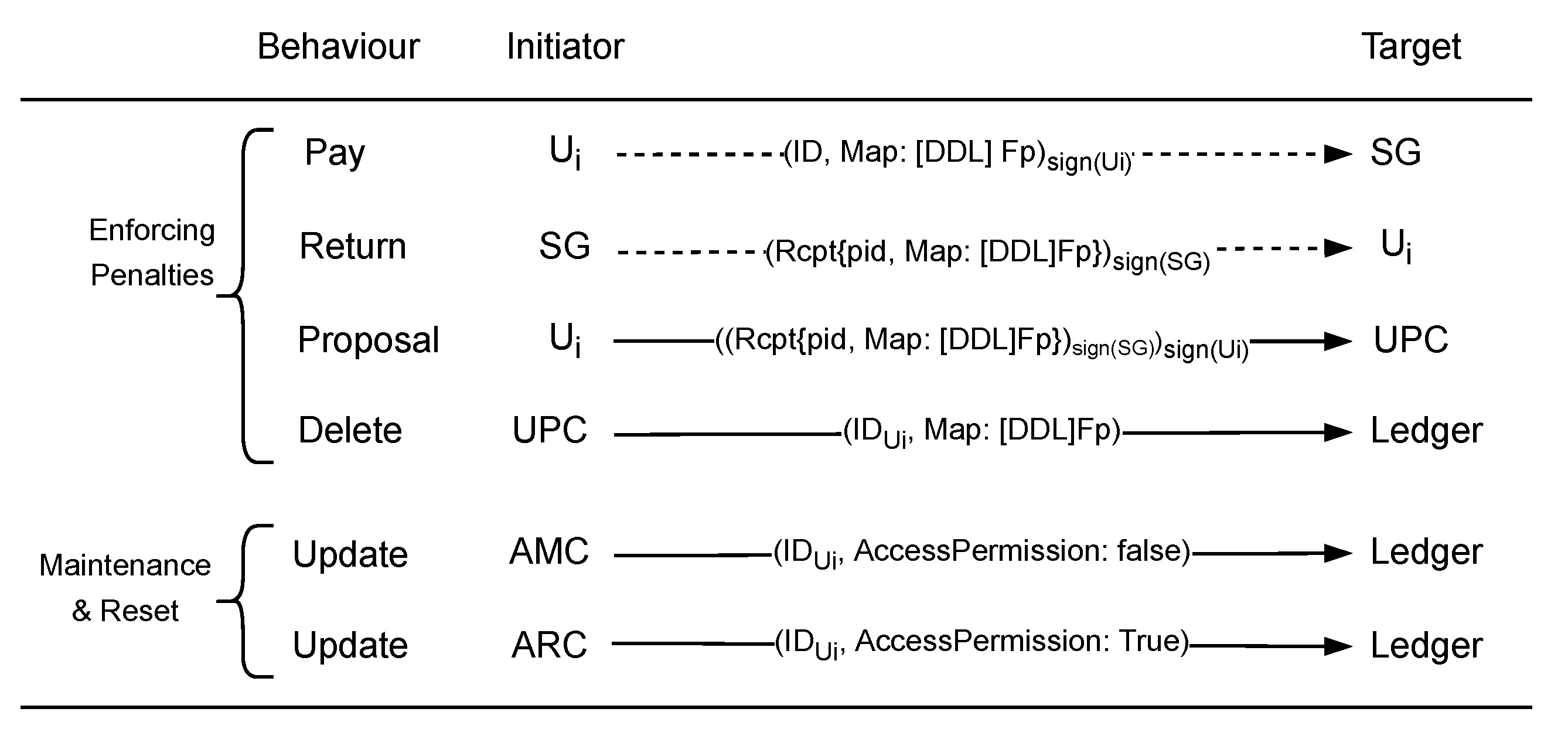
As shown in Figure 6, the enforcing penalties part is the entire flow of data from the user’s submission of the fine to the release of the penalty. The user signs the penalty M a p : [ D D L ] F p and submits it to S G along with the fine. When S G receives the penalty, it returns the signed r c p t p i d , M a p : [ D D L ] F p , where p i d is the receipt number of the penalty submission and M a p : [ D D L ] F p is used to release the penalty record in the user U a . U i adds the signature to the r c p t p i d , M a p : [ D D L ] F p and sends it to the UPC, which operates on the ledger via Algorithm 2.
Algorithm 2 User payment algorithm.
Input: (ID, Rcpt{pid, Map[DDL]Fp})
UserPayment:
if  p i d is the same as the proposal submission ID then
    Get F i n e s D e a d l i n e A n d F i n e s m a p from world state
    if  D D L and F p match F i n e s D e a d l i n e A n d F i n e s m a p  then
        Calculate malicious points ( M p ) that fines represent: M p = F p F p m × t h 1
        Delete the matching F i n e s D e a d l i n e A n d F i n e s m a p item from the user account,
        and update M a l i c i o u s P o i n t s as (old M a l i c i o u s P o i n t s M p ) to the user account
        Return
    else
        Error message: No corresponding fines found.
    end if
end if
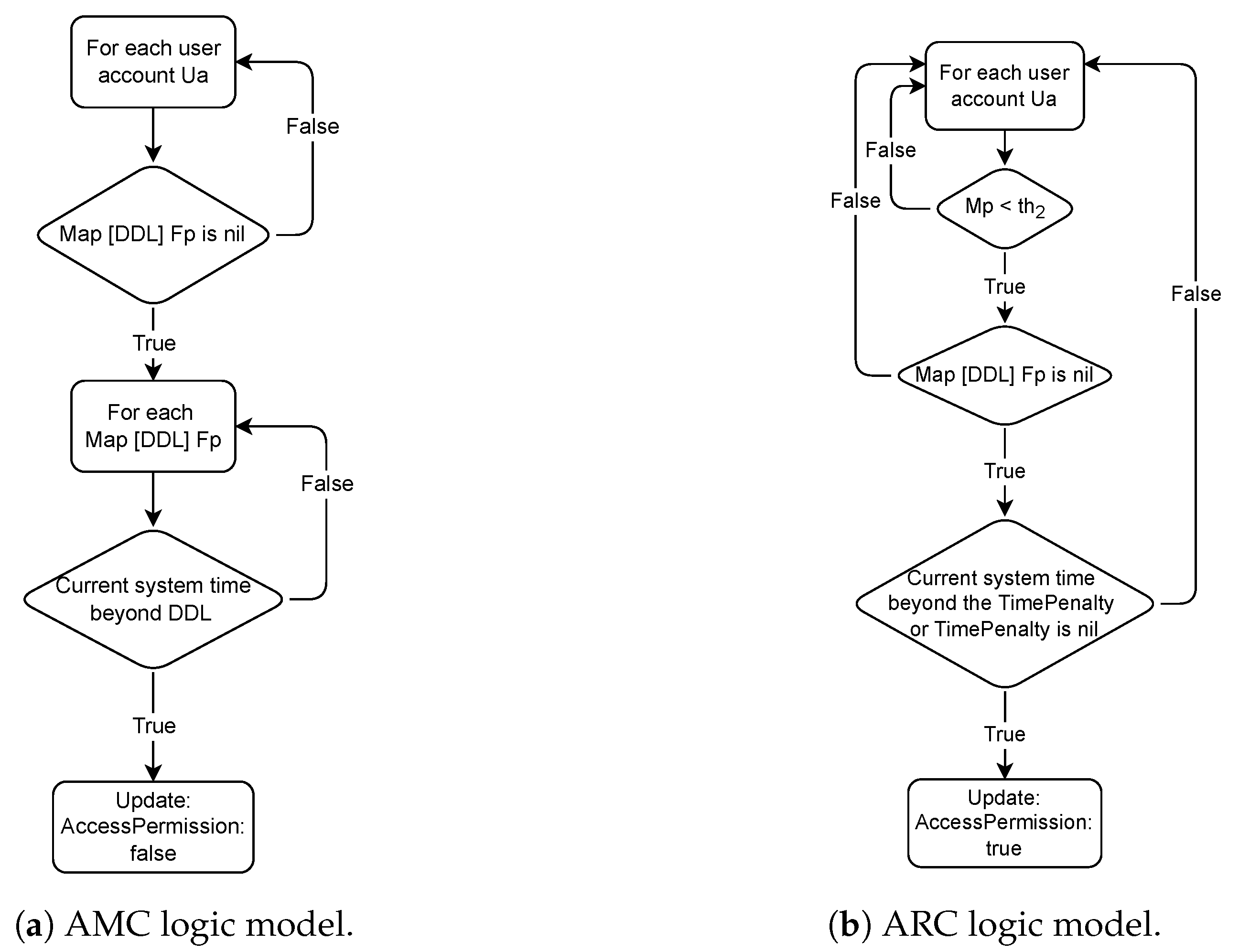
Maintenance and reset parts in Figure 6 show the further penalties set for the fine penalty and the release of those U i that complete the suspension penalty. For those U i that fail to submit the penalty in time, UMN removes their access and allows the S G to impose the suspension penalty through the AMC logic model in Figure 7a. In contrast, U i that have submitted a fine and met the conditions of the ARC in Figure 7b are released from the penalty.

6. Security Evaluation

The evaluation of security properties is an important indicator of whether the proposed system meets the design requirements. In this section, we analyse the following security properties of our scheme, namely, confidentiality and integrity. We also analyse how the proposed scheme will improve the security of the smart grid.

6.1. Assumptions Made

UMN is designed using the Hyperledger Fabric architecture, which incorporates the security mechanisms of Hyperledger Fabric [48]. We made the following assumptions to describe the UMN security properties formally. With these assumptions, we will demonstrate and verify whether the proposed system meets the security requirements.
Assumption 1. 
A t k cannot obtain the complete and usable user CA file U c a from any place where the U c a is stored (e.g., user local database and CA server).
Assumption 2. 
During information transmission, messages encrypted using TLS-CA [49] are secure and cannot be decrypted.
Assumption 3. 
The authentication tool used by A i can properly verify all honest U i .
Assumption 4. 
A i is honest in sending r e g i s t e r ( ) to the Fabric-CA server and returning the results to U i .
Assumption 5. 
I is not linked to ( I D , P w ) , and ( I D , P w ) cannot be generated directly using I.
Assumption 6. 
A t k cannot obtain U c a from Fabric-CA server without ( I D , P w ) .
Assumption 7. 
A t k cannot generate U c a directly using I.
Assumption 8. 
The monitoring node is honest and can output the correct malicious behaviour report M b r .
Assumption 9. 
Each action T will generate the correct result when the chaincode is executed correctly.
Assumption 10. 
The chaincode will only be executed automatically when the right preconditions are met.

6.2. Confidentiality

The purpose of confidentiality is to prevent any organisation’s unauthorised disclosure of system information. Access to confidential information, such as IDs, authorisation certificates, and private keys, is restricted to the data’s owner or authorised parties. If sensitive data are attacked and compromised, an attacker A t k can undermine system security by posing as an authorised person and accessing the compromised data.
In the proposed UMN, since its framework relies on Hyperledger Fabric as a permissioned blockchain, any user U i that wants to interact with the system and view system information must have a CA file U c a issued by the system’s Fabric-CA server. For instance, any time an U i wishes to authenticate a finished penalty, it must sign the proposal using the k e y s t o r e in U c a . Moreover, when U i wants to view other users’ account information, it must provide UMN with the s i g n c e r t in U c a to confirm its identity. If U c a is leaked (confidentiality is broken), the attacker A t k can disguise himself as the attacked user U i by forging U c a and entering the S G as U i . Any malicious behaviour that occurs after A t k enters the system is not traceable to A t k . Therefore, ensuring the confidentiality of U c a is important in maintaining system security. Assumptions 1 and 2 enable the risk of possible U c a disclosure to be concentrated in two parts (Proposition 1 and Proposition 2). We ensure that user CA files can satisfy confidentiality requirements by proving Propositions 1 and 2, respectively.
Proposition 1. 
During the phase of distribution, the confidentiality of U c a can be ensured.
Proof of Proposition 1. 
The distribution of U c a in UMN is implemented based on the steps shown in Figure 8. In the process of U i acquiring U c a , based on Assumptions 3 and 4, A i generates an I D and password P w (similar to a username and password) for the user during registration with Fabric-CA server and assigns roles and any required attributes to them. After successful registration, A i provides the I D and P w to U i , and U i uses ( I D , P w ) to request U c a directly from Fabric-CA. Combining with Figure 8, there are three types of participants in the distribution process: U i is the user who obtains U c a , A i is the admin who authenticates the real identity, and Fabric-CA server is the server deployed in the UMN system. With Assumptions 1–4, A t k cannot obtain U c a from any of the types of participants. Thus, it can be demonstrated that the confidentiality of user CA files can be maintained at the phase of U c a distribution, and Proposition 1 holds. □
Proposition 2. 
Any A t k cannot obtain U c a , even if it has U i ’s true identity I and disguises itself as U i .
Proof of Proposition 2. 
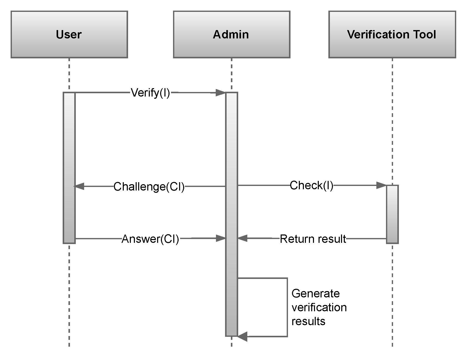
The verification process v e r i f y ( I ) of U i ’s real identity information I is performed by A i through the verification tool, and the sequence is shown in Figure 9. A i compares the I of the user with I in the authorisation database to verify I’s authenticity. Simultaneously, A i sends a challenge message C I , such as an SMS verification code, to U i to confirm its ownership of the I. Only when both the comparison result and the challenge result are correct will A i generate the verification result. In addition, A i verifies only once for each I and does not accept repeated verification.
  • If A t k uses I to try to obtain ( I D , P w ) through the registration process after U i has successfully registered and eventually obtained U c a , A i will reject it during the verification process.
  • If A t k tries to register using I before the first registration of U i , it still will not be able to pass the verification and obtain ( I D , P w ) during v e r i f y ( I ) because it cannot answer the C I correctly.
Based on Assumptions 5 and 6, A t k cannot generate ( I D , P w ) without relying on A i even if it has I. Without ( I D , P w ), A t k cannot obtain U c a from Fabric-CA server, and thus, A t k cannot obtain U c a by disguising as U i . Also based on Assumption 7, A t k cannot generate U c a by itself. Hence, Proposition 2 holds. □

6.3. Integrity

Data integrity illustrates the correctness and consistency of data throughout its life cycle (the entire process of data from the sender to the receiver) and cannot be modified by any unauthorised entity. The successful maintenance of data integrity prevents any party’s interests from being endangered by data modifications.
UMN is a consortium blockchain-driven system for recording and treating malicious user behaviour. Thus, any information processing and recording are done based on a ledger. A i needs to initialise the new user account U a by updating the ledger. M N i needs to update the ledger to complete the recording of malicious behaviour and the enforcement of penalties. U i needs to update the ledger for authentication after completing the penalties. S G needs to query the ledger to determine whether U i has permission to participate in electrical energy transactions. In any of the above scenarios, if A t k modifies the ledger, then UMN will lose its full validity as a system that provides accountability functions. Therefore, it is necessary to maintain the ledger’s integrity to ensure system security. Based on Assumption 8, the integrity analysis can be focused in Proposition 3.
Proposition 3. 
The data generated by action T in UMN maintain integrity during the life cycle.
Proof of Proposition 3. 
The set of actions T: { A , B , C , } in UMN contains two types, actions T α : { A α , B α , C α , } driven by proposals sent by external entities ϕ i and actions T β : { A β , B β , C β , } executed automatically due to the satisfaction of preconditions.
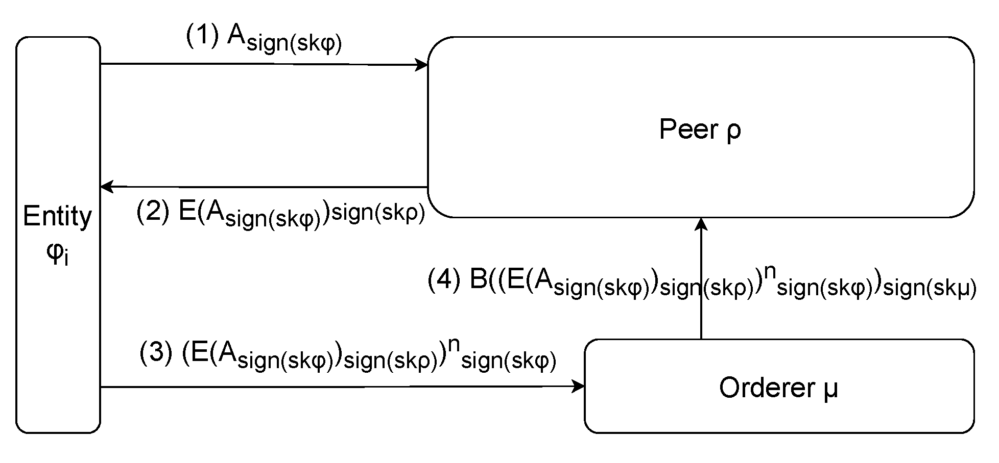
For a set of actions T α : { A α , B α , C α , } , the whole action process is shown in Figure 10. The action initiator ϕ i signs its content A s i g n ( s k ϕ ) and sends A s i g n ( s k ϕ ) to the peer node ρ , which verifies and executes it and then signs the result E ( A s i g n ( s k ϕ ) ) s i g n ( s k ρ ) and returns it to ϕ i . After ϕ i has collected a sufficient number n of the return results according to the endorsement policy, ϕ i will sign and submit ( E ( A s i g n ( s k ϕ ) ) s i g n ( s k ρ ) ) s i g n ( s k ϕ ) n ) to the ordering node μ . μ will generate blocks and attach signatures B ( ( E ( A s i g n ( s k ϕ ) ) s i g n ( s k ρ ) ) s i g n ( s k ϕ ) n ) s i g n ( s k μ ) after ordering the received results. Finally, all signatures will be verified by ρ , which maintains the ledger and will be updated to the blockchain when passed. Throughout the entire process, if Assumption 9 is satisfied, the integrity of the data can be guaranteed since each process of data transmission and generation contains the signature of the data operator or holder.
For the system set of actions T β : { A β , B β , C β , } , since it is an operation performed inside the system and does not interact with ϕ , based on Assumption 10, we can conclude that its integrity is satisfied.
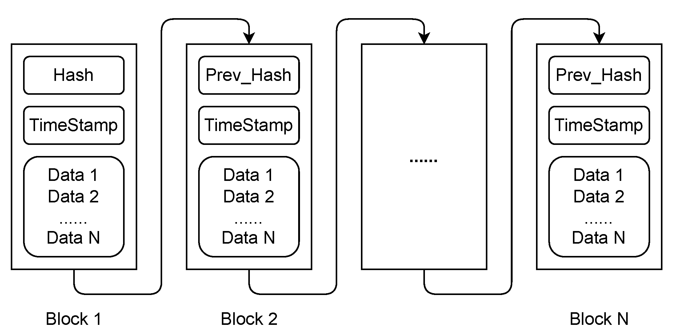
From the overall perspective, the logical structure of the blockchain we designed is shown in Figure 11. The data part of each block in the blockchain is arranged in chronological order, which means that what is recorded in each data is what happens in chronological order. Suppose the integrity of a part of d a t a i in the blockchain is corrupted, and the blockchain can be restored by tracing the previous result d a t a i 1 . Hence, Proposition 3 holds. □

6.4. Security Analysis

In order to analyse the security of the smart grid, we first review the relationship between the UMN and the smart grid. As shown in Figure 1, the UMN is a relatively independent system that only manages malicious behaviour information, records and enforces penalties. The system’s blockchain only records information related to malicious behaviour and does not logically share the ledger with the smart grid system. The smart grid acts as the entity that interacts with the system to enforce access control and penalty policies on malicious users. Based on this relationship, our discussion of improving smart grid security can focus on how the UMN interacts with the smart grid. The primary interaction between the smart grid system and the UMN consists of two parts. The interaction between the monitoring node in the UMN and the grid monitors for malicious behaviour and generates critical data. The interaction between the smart grid as an entity and the UMN reads information about malicious behaviour.
In the interaction between the monitoring node and the smart grid, the monitoring node is an observer, detecting malicious behaviour and running a malicious behaviour point generation program, and does not exchange information with the smart grid. Therefore, assuming that the monitoring node is secure at the physical and network layers, it poses no threat to the security of the smart grid. Similarly, in the interaction between the smart grid and the UMN, the smart grid entity will only read information from the UMN blockchain, as the integrity of the data is already proven in Section 6.3 during the reading process. Hence, the data read by the smart grid entity are authentic and valid and do not pose a new security risk. In summary, the security of the proposed solution is valid.

7. Performance Evaluation

In this section, we will evaluate the performance of the proposed scheme with a simulation setup. We evaluate two key elements that determine system performance: throughput and latency.

7.1. Experimental Setup

Our experimental setup consists of three parts. These include the prerequisites that have an impact on the experiment, the definition of throughput and latency and the setting of the experimental environment and parameters.
i
Prerequisites:
The results of this experiment are influenced by several factors, so for accurate evaluation and analysis, we place the following restrictions on the experimental variables.
First, we consider the block size, which indicates the number of proposals contained in each block. Research has shown that an increase in block size leads to an increase in throughput [50], and for this reason, in our experiments we fix the size of each submitted block. Simultaneously, we consider that during the whole proposal submission process, the peer processes one block at a time. Each proposal has the same complexity and is independent of each other. Secondly, the number of channels has an impact on system performance and scalability, as each channel handles different proposals independently. This experiment only discusses the case of a single channel.
ii
Definitions of Key Metrics:
The two key metrics used to evaluate performance for the experiments, throughput and latency, are defined in the Hyperledger Blockchain Performance Metrics white paper [51].
The transaction throughput is a measure of the rate at which a Hyperledger Fabric-based network environment commits valid transactions in a given period of time. A formal mathematical description can be expressed as
T r a n s a c t i o n T h r o u g h p u t = C o u n t ( T x i n ( t s , t e ) ) t e t s
In description (8), T x is the total number of submitted proposals, t s is the time of the initial proposal submission, and t e is the time of the last proposal submission.
Since the system needs time to validate transactions sent to the network, this validation time is expressed in terms of transaction latency. Specifically, the transaction latency is the time taken between the submission of a proposal and the end of validation. A formal mathematical description can be expressed as
T r a n s a c t i o n L a t e n c y = T x ( t v t p ) C o u n t ( T x i n ( t s , t e ) )
where t p is the time of the first commit of the T x transaction, and t v is the time of the successful validation of the T x transaction.
iii
Environment and Parameters: We list the tools used during the experiments as well as the configuration and parameters of the system in Table 4.

7.2. Experimental Evaluation

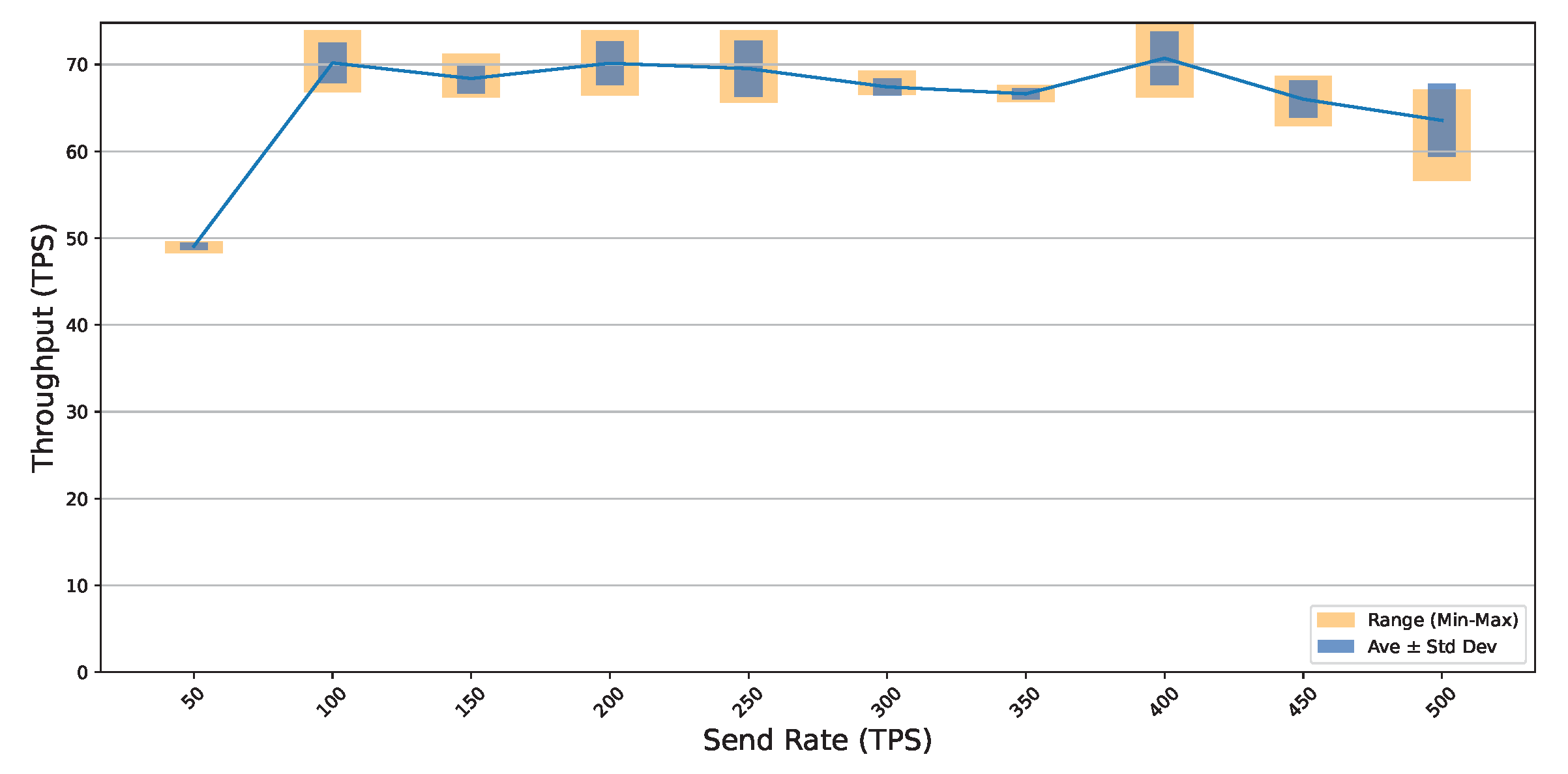
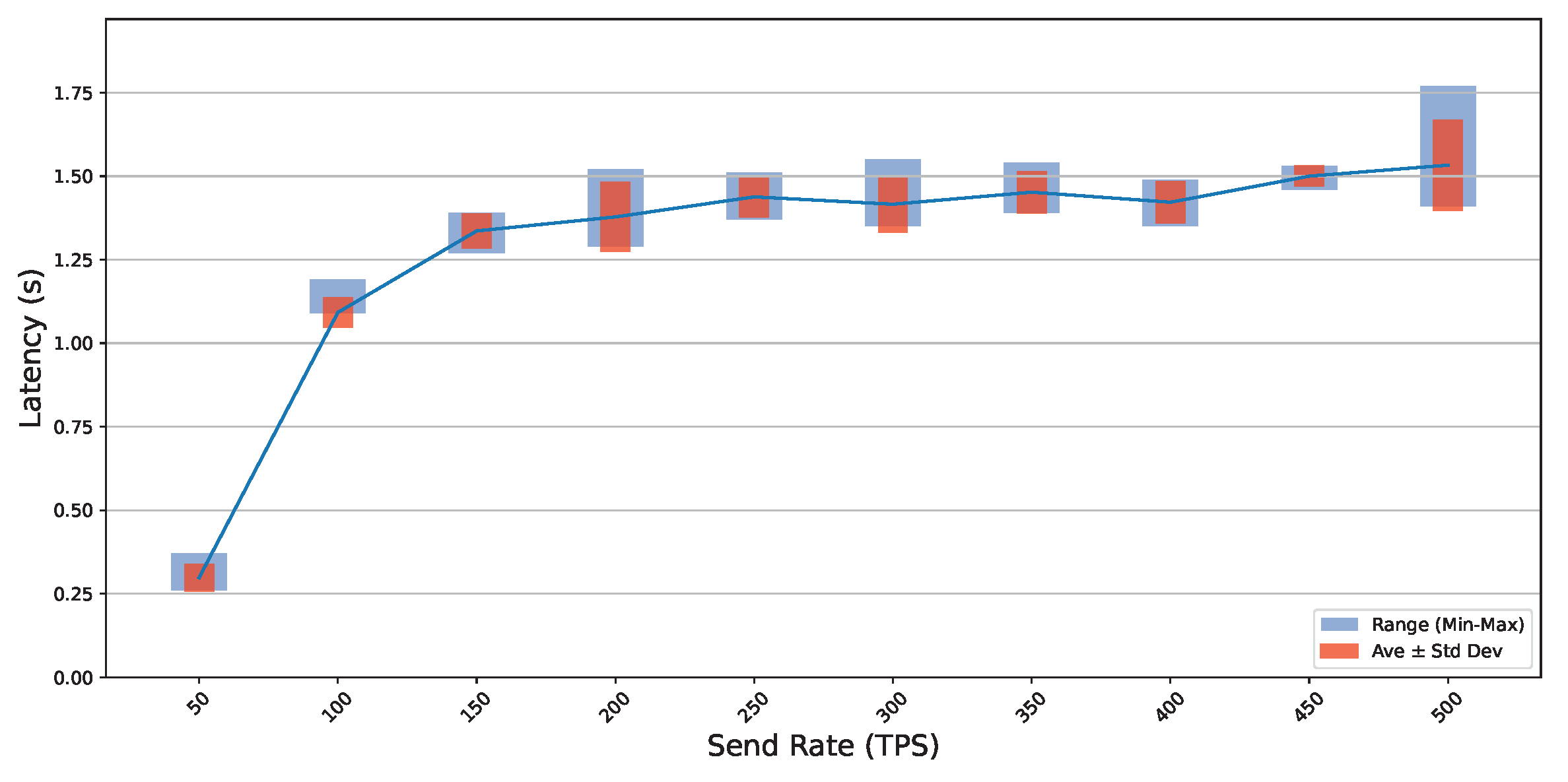
In order to evaluate the performance of our scheme in Hyperledger Fabric, we designed an experiment based on the environment and parameters set above. The experiment is repeated 50 times, and each time there are 1000 transactions at a few rates of 50, 100, 150, 200, 250, 300, 350, 400, 450, and 500 transactions per second (tps). We calculated the maximum, minimum, average and standard deviation of the results obtained from the tests.

Results

  • The throughput results from the caliper are shown in Figure 12. Throughout the experiment, the throughput increases linearly with increasing the transaction sending rates. After increasing the sending rate to 100 tps, the throughput peaked (70 tps) and levelled off. The above result shows that the maximum usable rate of the system is 70 tps. Meanwhile, there is a slight drop in throughput after the peak is reached, which is caused by a drop in the system performance when the load exceeds the peak.
  • The latency test results are shown in Figure 13. This chart depicts the latency of communication and the rate of the write transactions, where latency is measured in seconds. The latency in the chart stays very low at the beginning (0.298 s) at a send rate of 50 tps. As the transaction rate increases, the latency increases rapidly and continues to increase slowly after reaching full system capacity (100 tps). However, the latency remains under 1.6 s throughout the test range.
We tested throughput and latency to demonstrate that our system’s performance met the application standards. For our experimental results, we compared them with the benchmark results [52,53,54]. It turns out that our system has the same performance characteristics as the benchmark results. This shows that our system is stable and usable.

8. Discussion

We analysed four related works of literature in terms of seven features: data integrity, data confidentiality, traceability, access control, behaviour analysis, management strategy, and scalability. Data integrity ensures that data are not corrupted or tampered with during transmission and storage. Data confidentiality focuses on privacy and prevents unauthorised users from accessing sensitive information. The above two features discuss the literature mainly from the security dimension. It discusses whether the literature employs security techniques and whether it can ensure data security during the process or transmission. Traceability denotes the ability of a system to track history and to locate and fix faults when they occur quickly. Access control means the system can assign different access rights to different types of participants. We use traceability and access control to compare the reliability and robustness of different methods and to analyse whether the system has the ability to handle threats. Behaviour analysis is an algorithm or protocol that provides analysis of the behaviour of system users or entities. Behaviour analysis is used to detect system potentially malicious behaviour. The management strategy is to apply appropriate countermeasures to malicious behaviours. Two features, behaviour analysis and management strategy, are used to determine the system’s effectiveness in dealing with malicious behaviour. Scalability refers to the ability of a system to handle increasing workloads and data volumes effectively. This concept assesses whether the system is performing well regarding availability and performance. Table 5 shows the results of the comparison between each system in terms of security and various metrics.
In addition to the comparisons shown in Table 5, we found that the malicious behaviour detection, access control and other means described in the other schemes were theoretically effective in avoiding the impact of malicious behaviour on users. However, these schemes use the same means for all different malicious behaviours, and the penalties do not cause actual damage to the attacker. In contrast, our solution is designed with different penalties to ensure the security of the smart grid while reducing the impact of malicious behaviour and acting as a deterrent to malicious users. Meanwhile, in our proposed solution, we considered and analysed the potential impact of each malicious behaviour. We designed a penalty strategy to achieve the level of penalty by setting thresholds, and we have kept the strategy scalable so that organisers can customise different penalties. In terms of system design, we followed the Hyperledger Fabric design in detail and proposed five smart contracts with corresponding parameters to implement the penalties. Hence, our proposed solution is novel and effective in helping smart grids to limit and avoid the harm of malicious behaviour.

9. Future Work

The proposed scheme in this study includes a series of experiments on identifying malicious behaviour features, deployment monitoring, user authentication, access control, and behavioural activity tracking. We aim to solve the problem of malicious behaviour in the smart grid once and for all. The current scheme provides a theoretical basis and recommendations for subsequent experiments and research. Therefore, we will continue to work on a range of issues, for example, how to identify malicious behaviour characteristics, deploy monitoring nodes and track the behavioural activities of malicious nodes, authenticate and implement access control for users in the smart grid, and whether the penalty efficiency is realistic. This scheme uses blockchain rather than the usual database, mainly from the security point of view. Each block in a blockchain contains a link to previous transactions, so it has excellent history-tracking capabilities and the ability to protect data integrity. However, the blockchain itself may also have drawbacks in terms of scalability and sustainability compared to usual databases. At the same time, block bloating may lead to a decrease in the processing efficiency of the system with the increase in time. Therefore, we have to optimise the system’s performance and sustainability.

10. Conclusions

Smart grids are pivotal in the future energy landscape, offering a decentralised, transparent, and equitable trading model that entices active user engagement. This study is centred on the smart grid domain and seeks to tackle the issue of safeguarding the interests of legitimate suppliers and consumers in the face of malicious behaviour. To address this issue, we propose a management scheme (UMN) to handle different types of malicious behaviours in smart grids. UMN combines a consortium blockchain and the best–worst multi-criteria decision-making method (BWM) to quantify and manage malicious behaviour accurately. We use smart contracts to implement a penalty for different malicious users. By analysing the security properties of UMN and comparing it with state-of-the-art methods, we demonstrate the feasibility and innovativeness of our solution. We tested the performance of our scheme, and the results show that the performance curve of UNM has the same features as the benchmarking results.

Author Contributions

Conceptualization, Z.X., A.S.S. and C.R.; methodology, Z.X.; software, Z.X.; validation, Z.X., A.S.S. and C.R.; formal analysis, Z.X.; investigation, Z.X.; resources, Z.X.; data curation, Z.X.; writing—original draft preparation, Z.X.; writing—review and editing, Z.X., A.S.S. and C.R.; supervision, A.S.S. and C.R. All authors have read and agreed to the published version of the manuscript.

Funding

This research received no external funding.

Data Availability Statement

Not applicable.

Conflicts of Interest

The authors declare no conflict of interest.

Appendix A

Table A1. Summary of notations.
NotationExplanation
U i Users interested in participating in the smart grid.
A i Administrators responsible for authentication.
M N i Monitoring Nodes.
S G Smart Grid.
U a User accounts recorded in the ledger.
IUser’s identity verification information.
A p User permissions for accessing the smart grid.
M L Monitoring list generated by monitoring activities.
M b r Malicious behaviour reports.
M p Malicious points.
MSet of malicious behaviours.
( I D , P w ) Identifier and password pair for obtaining U c a .
U c a User certificate file.
M a p [ D D L ] F p Map of fines deadlines and fines.
F p Fines.
C I Challenge information for dual validation.
P i j Product of each malicious act M i for criteria weight w j * .
w j * Criteria weight as defined in Section 4.2.1.
tNumber of repetitions of malicious behaviour.
M b = { b 1 , , b n } Set of quantified malicious behaviour unit conditions, where b is the quantified value of a specific condition.
L p = { l 1 , , l n } Set of damages caused by malicious behaviour, where l represents the cumulative damage.
R m = { r 1 , , r n } Set of penalties for repeated malicious behavior, where r is the number of occurrences.
t h Threshold.
T p Time penalties.
A t k Perpetrators of malicious behaviour.
U R C User Registration Contract.
M B C Malicious Behaviour Contract.
A M C Account Maintenance Contract.
U P C User Payment Contract.
A R C Account Reset Contract.

References

  1. Farhangi, H. The path of the smart grid. IEEE Power Energy Mag. 2009, 8, 18–28. [Google Scholar] [CrossRef]
  2. Lo, C.H.; Ansari, N. Decentralized controls and communications for autonomous distribution networks in smart grid. IEEE Trans. Smart Grid 2012, 4, 66–77. [Google Scholar] [CrossRef]
  3. Kim, Y.J.; Thottan, M.; Kolesnikov, V.; Lee, W. A secure decentralized data-centric information infrastructure for smart grid. IEEE Commun. Mag. 2010, 48, 58–65. [Google Scholar] [CrossRef]
  4. Nakamoto, S. Bitcoin: A peer-to-peer electronic cash system. Decentralized Bus. Rev. 2008. Available online: https://bitcoin.org/bitcoin.pdf (accessed on 15 September 2023).
  5. Xu, Z.; Salehi Shahraki, A.; Rudolph, C. Blockchain Applications in Smart Grid. In Australasian Computer Science Week 2022; ACM: New York, NY, USA, 2022; pp. 37–45. [Google Scholar]
  6. Agung, A.A.G.; Handayani, R. Blockchain for smart grid. J. King Saud-Univ.-Comput. Inf. Sci. 2022, 34, 666–675. [Google Scholar] [CrossRef]
  7. Khattak, H.A.; Tehreem, K.; Almogren, A.; Ameer, Z.; Din, I.U.; Adnan, M. Dynamic pricing in industrial internet of things: Blockchain application for energy management in smart cities. J. Inf. Secur. Appl. 2020, 55, 102615. [Google Scholar] [CrossRef]
  8. Guan, Z.; Si, G.; Zhang, X.; Wu, L.; Guizani, N.; Du, X.; Ma, Y. Privacy-preserving and efficient aggregation based on blockchain for power grid communications in smart communities. IEEE Commun. Mag. 2018, 56, 82–88. [Google Scholar] [CrossRef]
  9. Sicari, S.; Rizzardi, A.; Grieco, L.A.; Coen-Porisini, A. Security, privacy and trust in Internet of Things: The road ahead. Comput. Netw. 2015, 76, 146–164. [Google Scholar] [CrossRef]
  10. Hasan, M.K.; Alkhalifah, A.; Islam, S.; Babiker, N.; Habib, A.; Aman, A.H.M.; Hossain, M.A. Blockchain technology on smart grid, energy trading, and big data: Security issues, challenges, and recommendations. Wirel. Commun. Mob. Comput. 2022, 2022, 9065768. [Google Scholar] [CrossRef]
  11. Gao, J.; Asamoah, K.O.; Sifah, E.B.; Smahi, A.; Xia, Q.; Xia, H.; Zhang, X.; Dong, G. GridMonitoring: Secured sovereign blockchain based monitoring on smart grid. IEEE Access 2018, 6, 9917–9925. [Google Scholar] [CrossRef]
  12. HS, J. Reputation management in vehicular network using blockchain. Peer-to-Peer Netw. Appl. 2022, 15, 901–920. [Google Scholar]
  13. Alnasser, A.; Sun, H. A fuzzy logic trust model for secure routing in smart grid networks. IEEE Access 2017, 5, 17896–17903. [Google Scholar] [CrossRef]
  14. Kumari, A.; Patel, M.M.; Shukla, A.; Tanwar, S.; Kumar, N.; Rodrigues, J.J. ArMor: A data analytics scheme to identify malicious behaviors on blockchain-based smart grid system. In Proceedings of the GLOBECOM 2020—2020 IEEE Global Communications Conference, Taipei, Taiwan, 7–11 December 2020; pp. 1–6. [Google Scholar]
  15. Rezaei, J. Best-worst multi-criteria decision-making method. Omega 2015, 53, 49–57. [Google Scholar] [CrossRef]
  16. Androulaki, E.; Barger, A.; Bortnikov, V.; Cachin, C.; Christidis, K.; De Caro, A.; Enyeart, D.; Ferris, C.; Laventman, G.; Manevich, Y.; et al. Hyperledger fabric: A distributed operating system for permissioned blockchains. In Proceedings of the 13th EuroSys Conference, Porto, Portugal, 23–26 April 2018; pp. 1–15. [Google Scholar]
  17. Hyperledger Fabric CA Docs. Hyperledger Fabric CA User’s Guide; Hyperledger Foundation: San Francisco, CA, USA, 2017. Available online: https://hyperledger-fabric-ca.readthedocs.io/en/latest/users-guide.html (accessed on 2 October 2023).
  18. Mollah, M.B.; Zhao, J.; Niyato, D.; Lam, K.Y.; Zhang, X.; Ghias, A.M.; Koh, L.H.; Yang, L. Blockchain for future smart grid: A comprehensive survey. IEEE Internet Things J. 2020, 8, 18–43. [Google Scholar] [CrossRef]
  19. Goel, S.; Hong, Y. Security challenges in smart grid implementation. In Smart Grid Security; Springer: Berlin/Heidelberg, Germany, 2015; pp. 1–39. [Google Scholar]
  20. Rahiminejad, A.; Plotnek, J.; Atallah, R.; Dubois, M.A.; Malatrait, D.; Ghafouri, M.; Mohammadi, A.; Debbabi, M. A resilience-based recovery scheme for smart grid restoration following cyberattacks to substations. Int. J. Electr. Power Energy Syst. 2023, 145, 108610. [Google Scholar] [CrossRef]
  21. Kabalci, Y. A survey on smart metering and smart grid communication. Renew. Sustain. Energy Rev. 2016, 57, 302–318. [Google Scholar] [CrossRef]
  22. Aoufi, S.; Derhab, A.; Guerroumi, M. Survey of false data injection in smart power grid: Attacks, countermeasures and challenges. J. Inf. Secur. Appl. 2020, 54, 102518. [Google Scholar] [CrossRef]
  23. Gunduz, M.Z.; Das, R. Cyber-security on smart grid: Threats and potential solutions. Comput. Netw. 2020, 169, 107094. [Google Scholar] [CrossRef]
  24. Yang, Y.; Littler, T.; Sezer, S.; McLaughlin, K.; Wang, H. Impact of cyber-security issues on smart grid. In Proceedings of the 2011 2nd IEEE PES International Conference and Exhibition on Innovative Smart Grid Technologies, Manchester, UK, 5–7 December 2011; pp. 1–7. [Google Scholar]
  25. El Mrabet, Z.; Kaabouch, N.; El Ghazi, H.; El Ghazi, H. Cyber-security in smart grid: Survey and challenges. Comput. Electr. Eng. 2018, 67, 469–482. [Google Scholar] [CrossRef]
  26. Liu, J.; Xiao, Y.; Gao, J. Achieving accountability in smart grid. IEEE Syst. J. 2013, 8, 493–508. [Google Scholar] [CrossRef]
  27. Melo, W. Blockchains and legal metrology: Applications and possibilities. OIML Bull. 2021, 62, 10–20. [Google Scholar]
  28. Miličević, K.; Tolić, I.; Vinko, D.; Horvat, G. Blockchain-Based Concept for Digital Transformation of Traceability Pyramid for Electrical Energy Measurement. Sensors 2022, 22, 9292. [Google Scholar] [CrossRef]
  29. Ibrahem, M.I.; Nabil, M.; Fouda, M.M.; Mahmoud, M.M.; Alasmary, W.; Alsolami, F. Efficient privacy-preserving electricity theft detection with dynamic billing and load monitoring for AMI networks. IEEE Internet Things J. 2020, 8, 1243–1258. [Google Scholar] [CrossRef]
  30. Ashfaq, T.; Khalid, R.; Yahaya, A.S.; Aslam, S.; Azar, A.T.; Alsafari, S.; Hameed, I.A. A machine learning and blockchain based efficient fraud detection mechanism. Sensors 2022, 22, 7162. [Google Scholar] [CrossRef]
  31. Jeffin, M.; Madhu, G.; Rao, A.; Singh, G.; Vyjayanthi, C. Internet of things enabled power theft detection and smart meter monitoring system. In Proceedings of the 2020 International Conference on Communication and Signal Processing (ICCSP), Chennai, India, 28–30 July 2020; pp. 0262–0267. [Google Scholar]
  32. Aman, M.N.; Javed, K.; Sikdar, B.; Chua, K.C. Detecting data tampering attacks in synchrophasor networks using time hopping. In Proceedings of the 2016 IEEE PES Innovative Smart Grid Technologies Conference Europe (ISGT-Europe), Ljubljana, Slovenia, 9–12 October 2016; pp. 1–6. [Google Scholar]
  33. Ali, S.; Li, Y. Learning multilevel auto-encoders for DDoS attack detection in smart grid network. IEEE Access 2019, 7, 108647–108659. [Google Scholar] [CrossRef]
  34. Chatfield, B.; Haddad, R.J.; Chen, L. Low-computational complexity intrusion detection system for jamming attacks in smart grids. In Proceedings of the 2018 International Conference on Computing, Networking and Communications (ICNC), Maui, HI, USA, 5–8 March 2018; pp. 367–371. [Google Scholar]
  35. Xue, A.; Xu, F.; Chow, J.H.; Leng, S.; Kong, H.; Xu, J.; Bi, T. Data-driven detection for GPS spoofing attack using phasor measurements in smart grid. Int. J. Electr. Power Energy Syst. 2021, 129, 106883. [Google Scholar] [CrossRef]
  36. He, Y.; Mendis, G.J.; Wei, J. Real-time detection of false data injection attacks in smart grid: A deep learning-based intelligent mechanism. IEEE Trans. Smart Grid 2017, 8, 2505–2516. [Google Scholar] [CrossRef]
  37. Weerapanpisit, P.; Trilles, S.; Huerta, J.; Painho, M. A decentralized location-based reputation management system in the IoT using blockchain. IEEE Internet Things J. 2022, 9, 15100–15115. [Google Scholar] [CrossRef]
  38. Melo, W.; Carmo, L.F.; Bessani, A.; Neves, N.; Santin, A. How blockchains can improve measuring instruments regulation and control. In Proceedings of the 2018 IEEE International Instrumentation and Measurement Technology Conference (I2MTC), Houston, TX, USA, 14–17 May 2018; pp. 1–6. [Google Scholar]
  39. Liang, X.; Zhao, Q.; Zhang, Y.; Liu, H.; Zhang, Q. EduChain: A highly available education consortium blockchain platform based on Hyperledger Fabric. Concurr. Comput. Pract. Exp. 2021, 35, e6330. [Google Scholar] [CrossRef]
  40. Alhajri, M.; Rudolph, C.; Shahraki, A.S. A Blockchain-Based Consent Mechanism for Access to Fitness Data in the Healthcare Context. IEEE Access 2022, 10, 22960–22979. [Google Scholar] [CrossRef]
  41. Shahraki, A.S.; Rudolph, C.; Grobler, M. Attribute-based data access control for multi-authority system. In Proceedings of the 2020 IEEE 19th International Conference on Trust, Security and Privacy in Computing and Communications (TrustCom), Guangzhou, China, 29 December 2020–1 January 2021; pp. 1834–1841. [Google Scholar]
  42. Salehi, A.; Han, R.; Rudolph, C.; Grobler, M. DACP: Enforcing a dynamic access control policy in cross-domain environments. Comput. Networks 2023, 237, 110049. [Google Scholar] [CrossRef]
  43. Liu, H.; Han, D.; Li, D. Fabric-IoT: A blockchain-based access control system in IoT. IEEE Access 2020, 8, 18207–18218. [Google Scholar] [CrossRef]
  44. Ahmad, R.W.; Hasan, H.; Jayaraman, R.; Salah, K.; Omar, M. Blockchain applications and architectures for port operations and logistics management. Res. Transp. Bus. Manag. 2021, 41, 100620. [Google Scholar] [CrossRef]
  45. Ma, C.; Kong, X.; Lan, Q.; Zhou, Z. The privacy protection mechanism of Hyperledger Fabric and its application in supply chain finance. Cybersecurity 2019, 2, 5. [Google Scholar] [CrossRef]
  46. Valenta, M.; Sandner, P. Comparison of ethereum, hyperledger fabric and corda. Frankf. Sch. Blockchain Cent. 2017, 8, 1–8. [Google Scholar]
  47. Camenisch, J.; Mödersheim, S.; Sommer, D. A formal model of identity mixer. In Proceedings of the International Workshop on Formal Methods for Industrial Critical Systems, Antwerp, Belgium, 20–21 September 2010; pp. 198–214. [Google Scholar]
  48. Li, D.; Peng, W.; Deng, W.; Gai, F. A blockchain-based authentication and security mechanism for IoT. In Proceedings of the 2018 27th International Conference on Computer Communication and Networks (ICCCN), Hangzhou, China, 30 July–2 August 2018; pp. 1–6. [Google Scholar]
  49. Tam, K. TLS in Hyperledger Fabric. Available online: https://kctheservant.medium.com/tls-in-hyperledger-fabric-b38fccb8614c (accessed on 26 May 2022).
  50. Kuzlu, M.; Pipattanasomporn, M.; Gurses, L.; Rahman, S. Performance analysis of a hyperledger fabric blockchain framework: Throughput, latency and scalability. In Proceedings of the 2019 IEEE International Conference on Blockchain (Blockchain), Atlanta, GA, USA, 14–17 July 2019; pp. 536–540. [Google Scholar]
  51. Hyperledger Performance and Scale Working Group Hyperledger Blockchain Performance Metrics White Paper. Available online: https://www.hyperledger.org/learn/publications/blockchain-performance-metrics (accessed on 31 October 2018).
  52. Baliga, A.; Solanki, N.; Verekar, S.; Pednekar, A.; Kamat, P.; Chatterjee, S. Performance characterization of hyperledger fabric. In Proceedings of the 2018 Crypto Valley Conference on Blockchain Technology (CVCBT), Zug, Switzerland, 20–22 June 2018; pp. 65–74. [Google Scholar]
  53. Thakkar, P.; Nathan, S.; Viswanathan, B. Performance benchmarking and optimizing hyperledger fabric blockchain platform. In Proceedings of the 2018 IEEE 26th International Symposium on Modeling, Analysis, and Simulation of Computer and Telecommunication Systems (MASCOTS), Milwaukee, WI, USA, 25–28 September 2018; pp. 264–276. [Google Scholar]
  54. Nasir, Q.; Qasse, I.A.; Abu Talib, M.; Nassif, A.B. Performance analysis of hyperledger fabric platforms. Secur. Commun. Netw. 2018, 2018, 3976093. [Google Scholar] [CrossRef]
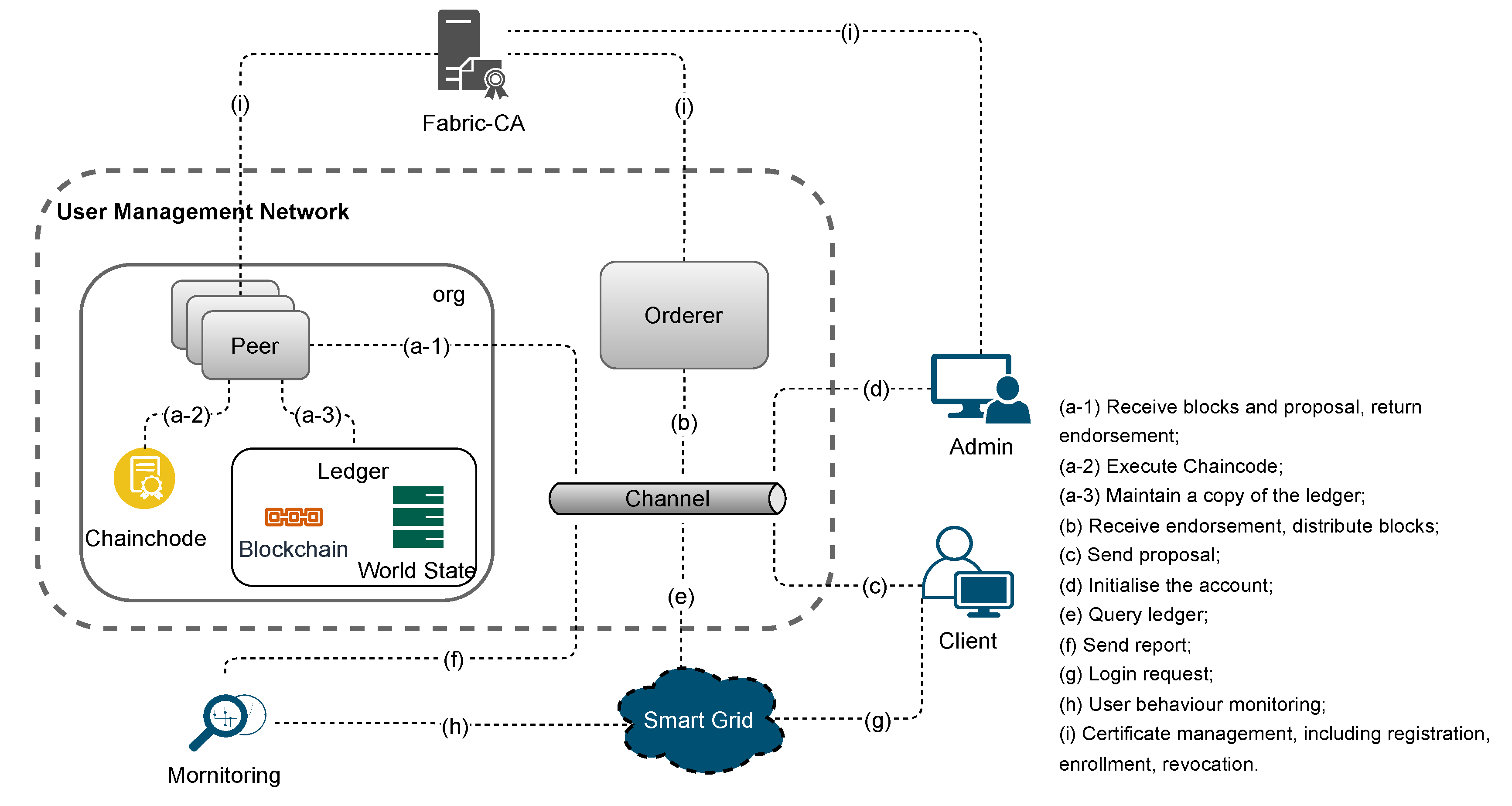
Figure 1. Proposed user management network (UMN) architecture with the behaviour of each part shown.
Smartcities 06 00135 g001
Figure 2. The monitoring node’s workflow from collecting malicious behaviour to generating malicious points.
Smartcities 06 00135 g002
Figure 3. Penalty workflow, where the green section is for warnings, the yellow and red sections are for primary penalties and the purple section is for advanced penalties.
Smartcities 06 00135 g003
Figure 4. Proposal workflow from request sent to ledger update in Hyperledger Fabric.
Smartcities 06 00135 g004
Figure 5. Sequence diagram of the monitoring and malicious behaviour handling phase.
Smartcities 06 00135 g005
Figure 6. Data flow of the proposed scheme, where the dotted line denotes off-chain operation and the solid line refers to on-chain operation.
Smartcities 06 00135 g006
Figure 7. Logic models.
Smartcities 06 00135 g007
Figure 8. Process for users to obtain CA files.
Smartcities 06 00135 g008
Figure 9. Identity verification sequence diagram.
Smartcities 06 00135 g009
Figure 10. Signature process to ensure data integrity.
Smartcities 06 00135 g010
Figure 11. Blockchain structure.
Smartcities 06 00135 g011
Figure 12. Throughput test results.
Smartcities 06 00135 g012
Figure 13. Latency test results.
Smartcities 06 00135 g013
Table 1. Literature review.
Malicious Behaviour Name and DefinitionLiterature Review
Electricity Theft: Malicious users lower their billing costs by reporting false readings.Ref. [29] presents a model for fraud detection using machine learning. The model utilises the inner product operation on encrypted readings to evaluate the machine learning model for detecting electricity theft.
Transaction Fraud: Trading with illegitimate accounts.Ref. [30] proposes a security fraud detection model based on machine learning and blockchain technology. The model detects transaction fraud by predicting how incoming transactions behave through XGboost and Random Forest (RF) algorithms.
Meter bypass, meter tampering and direct line hookups.Ref. [31] uses linear regression methods to continuously monitor smart meter data to detect electricity theft. And they develop an application to monitor the consumer’s electricity usage.
Data tampering: An attacker tampers the data in a Phasor Measurement Unit (PMU) packet.Ref. [32] proposed a randomised time-hopping sequence protocol. This random time-hopping sequence is generated from a secret seed shared by the Phasor Measurement Unit (PMU) and the Phase Data Concentrator (PDC).
Distributed Denial of Service (DDoS): Nodes send a large number of false data packets or execution requests to target servers, which result in the denial of service to legal users.Ref. [33] introduces multilevel auto-encoder-based feature learning. Features are generated by unsupervised learning of multilevel shallow and deep auto-encoders and combined with an efficient multi-kernel learning (MKL) algorithm to generate a detection model.
Jamming: By transmitting high-powered radio signals of the same frequency to jam network operations.Ref. [34] develops an intrusion detection system (IDS) to analyse the received signal strength indicator (RSSI) and packet loss rate (PLR) of 802.11 network traffic in smart grid communication systems to detect interference attacks.
GPS spoofing: Forging GPS signals to provide wrong time signals to geographically dispersed Phasor Measurement Units (PMU).Ref. [35] detects GPS spoofing attacks by monitoring the change of historical statistics and abrupt change index in Phasor Measurement Unit (PMU) data.
False Data Injection: Injecting malicious measurements into a hacked meter.Ref. [36] utilise deep learning methods to identify behavioural features associated with historical measurement data related to false data injection attacks and then employs these captured features for the real-time detection of such attacks.
Table 2. Malicious Behavior List.
Malicious Behavior MQuantitative Value P of the Criterion wTimes of Malicious Behavior Repeated
w 1 * w 2 * w n *
M 1 P 11 P 12 P 1 n t
Table 3. Data structure of user accounts in the world state and blockchain.
Variable NameData TypesInitial DataJson
IDstringUser IDjson:”ID”
UserNamestringUser Namejson:”username”
AccessPermissionbooltruejson:”accesspermission”
MaliciousBehaviourstringniljson:”maliciousbehaviour”
MaliciousPointsint0json:”maliciouspoints”
FinesDeadlineAndFinesmapmap[date]intniljson:”[finesdeadline]fines”
TimePenaltydateniljson:”timepenalty”
TimeStampdateSystem time at registrationjson:”timestamp”
Table 4. Parameters and metrics.
ParametersValues
Benchmarking Tool:Hyperledger caliper v0.5.0.
CPU:4 Core CPU (Intel i5-10210U CPU @ 1.60 GHz).
Memory:4 GB.
SSD:120 GB.
Network:25 Mbps.
Virtual Machines:Oracle VM VirtualBox.
System:Ubuntu 18.04.
Hyperledger Fabric Version:Hyperledger Fabric release v1.4.7.
Channels:1 Channel.
World State Database:CouchDB.
Block Size:20.
Consensus Mechanism:Raft.
Table 5. Comparison with related system.
Features[11][12][13][14]Our Work
Data Integrity
Data Confidentiality
Traceability
Access control
behaviour analysis
management strategy
Scalability
Disclaimer/Publisher’s Note: The statements, opinions and data contained in all publications are solely those of the individual author(s) and contributor(s) and not of MDPI and/or the editor(s). MDPI and/or the editor(s) disclaim responsibility for any injury to people or property resulting from any ideas, methods, instructions or products referred to in the content.