Article

Closed-Form Solution Lagrange Multipliers in Worst-Case Performance Optimization Beamforming

1
College of Information Engineering, Dalian University, Dalian 116622, China
2
Key Laboratory of Modern Communication and Beidou Positioning Technology in Universities of Fujian Province, Quanzhou University of Information Engineering, Quanzhou 326000, China
*
Authors to whom correspondence should be addressed.
Signals 2025, 6(4), 55; https://doi.org/10.3390/signals6040055 (registering DOI)
Submission received: 28 July 2025 / Revised: 17 September 2025 / Accepted: 24 September 2025 / Published: 4 October 2025

Abstract

This study presents a method for deriving closed-form solutions for Lagrange multipliers in worst-case performance optimization (WCPO) beamforming. By approximating the array-received signal autocorrelation matrix as a rank-1 Hermitian matrix using the low-rank approximation theory, analytical expressions for the Lagrange multipliers are derived. The method was first developed for a single plane wave scenario and then generalized to multiplane wave cases with an autocorrelation matrix rank of N. Simulations demonstrate that the proposed Lagrange multiplier formula exhibits a performance comparable to that of the second-order cone programming (SOCP) method in terms of signal-to-interference-plus-noise ratio (SINR) and direction-of-arrival (DOA) estimation accuracy, while offering a significant reduction in computational complexity. The proposed method requires three orders of magnitude less computation time than the SOCP and has a computational efficiency similar to that of the diagonal loading (DL) technique, outperforming DL in SINR and DOA estimations. Fourier amplitude spectrum analysis revealed that the beamforming filters obtained using the proposed method and the SOCP shared frequency distribution structures similar to the ideal optimal beamformer (MVDR), whereas the DL method exhibited distinct characteristics. The proposed analytical expressions for the Lagrange multipliers provide a valuable tool for implementing robust and real-time adaptive beamforming for practical applications.

1. Introduction

Adaptive beamforming technology has been widely applied in radar, sonar, wireless communication, acoustic signal processing, medical imaging, and radio astronomy. Minimum-variance distortionless response (MVDR) beamforming can achieve optimal performance by maximizing the signal-to-interference plus-noise ratio (SINR) under ideal conditions. However, in practical applications, the beamforming performance is significantly degraded by various factors, such as array element placement errors, direction-of-arrival (DOA) estimation errors, mutual coupling of array elements, gain and phase errors of array sensors, and perturbations in array element positions [1,2,3,4,5,6]. Over the past three decades, numerous robust and adaptive beamforming algorithms have been developed for various applications. Numerous researchers classify these factors into an uncertainty set of steering vectors and an autocorrelation matrix [7,8,9,10,11,12,13,14,15]. One of the key research directions is the optimization of worst-case performance beamforming, whose mathematical model is a quadratic programming problem with constraints [1,7,8,9,10]. The Lagrange multiplier method is one approach for solving this problem [11,12,13,14,15]. However, no closed-form solution is provided for the Lagrange multiplier in this case [11,12,13,14,15]. Reference [12] provides a lower bound for the Lagrange multiplier λ and uses numerical methods to iteratively determine an approximate solution to this problem. Owing to the lack of a closed-form solution for the Lagrange multiplier λ, the second-order conic programming (SOCP) method has been used to numerically solve the optimization problem [11,12,13,15]. As numerical iterative methods require large computing resources and more computing time, it is difficult to satisfy the requirements of online real-time processing scenarios.
Reference [14] explored the robust Capon beamforming guidance vector estimation problem and provided an expression for the Lagrange multiplier of the guidance vector. However, an analysis formula for the Lagrange multiplier for the worst-case performance optimization has not yet been reported. To date, the solution to the Lagrange multiplier for the worst-case performance optimization requires time iterations or recursion methods because there is no analysis formula. Because robust adaptive beamforming works online, it is necessary to search for a formula for a Lagrange multiplier. This was the motivation for this study. This study begins by modelling the problem using a planar-wave irradiation array. Using low-rank approximation theory, the array received signal autocorrelation matrix was approximated as a rank-1 Hermitian matrix, which allowed the derivation of the analytical expression for the Lagrange multiplier using matrix inversion formulas. We obtained a closed formula for the Lagrange multiplier, although it has some limitations. We further develop a more general closed formula for multiplanewave signals. Computer simulations demonstrated that these formulas are suitable for optimizing worst-case beamforming in general scenarios and exhibit excellent performance similar to that of SOCP.
The remainder of this paper is organized as follows: Section 2 describes the worst-case performance optimization (WCPO) model. In Section 3, we study a single signal impinging on a sensor array scenario to obtain the Lagrange multiplier solution formula, and then generalize this method to a multi-signal scenario to obtain the Lagrange multiplier solution formula in the form of an implicit function. The simulation and analysis of the proposed Lagrange multiplier solving formula are presented in Section 4. Section 5 deals with the discussion of the theoretical approximation and simulation results. Finally, Section 6 concludes the study.
Notation: Boldface in lower case letters represent vectors, and boldface in uppercase letters represent matrices. The notations ( · ) T and ( · ) H represent the transpose and conjugate transpose operators, respectively. t r ( · ) denotes the trace of a matrix. DL and LSMI are used interchangeably, as are OPT and MVDR.

2. Mathematical Model of the Problem and Current Results

Let the uniform linear observation array contain N sensor elements with an interval distance of half the wavelength λ. The desired signal is a narrowband signal in the far field with an incident angle θ, and the signal received by the array can be expressed as [9,10,15]
x ( k ) = s ( k ) + i ( k ) + n ( k ) , k = 1 , 2 ,
where s(k), i(k), and n(k) denote the desired, interference, and noise signals, respectively. The noise was assumed to have a white Gaussian distribution with a zero mean and variance of σ2 = 1. The steering vectors of signals are
a ( θ i ) = 1 , exp ( j 2 π ( f 0 / c ) d sin ( θ i ) , , exp ( j 2 π ( f 0 / c ) ( N 1 ) d sin ( θ i ) T , i = 1 , 2 , , I .
where θi denotes the desired and interference signal, I denotes signal number and f0 and c denote the signal frequency and wave velocity, respectively. The design goal of the WCPO method is to ensure that all steering vectors of the desired signal remain undamped, while achieving maximum suppression of interference and noise through adaptive beamforming. The mathematical model is expressed as follows [9,10]:
min w w H R w s . t . w H ( a + e ) 1 , e ε
where R = 1 / M k = 1 M x ( k ) x H ( k ) . M denotes the number of snapshots, w denotes a weight vector, and a, e, and ε represent the steering vector of the expected signal, the error vector between the steering vector of the expected signal and that of the received signal, and upper bound of the 2-norm of the above error, respectively. Equation (3) is a nonlinear, nonconvex set optimization problem. In [5], the constraint of (3), by contradiction, can be changed to w H a 1 2 2 = ε 2 w H w , which can be further expanded as [11,12]
w H ( ε 2 I a a H ) w + 2 a H w 1 = 0
Therefore, the original problem (3) is equivalent to the following convex optimization problem.
min w w H R w   s . t . w H ( ε 2 I a a H ) w + 2 a H w 1 = 0
The beamforming vector derived from the unconstrained condition of the Lagrange function is presented in [11] as shown as
w = λ ( R + λ ε 2 I ) 1 a / ( λ a H ( R + λ ε 2 I ) 1 a 1 )
Equation (6) is a function of the Lagrange multiplier, that is, w = w(λ); thus, it is not the final solution to Equation (3).
To date, most solutions to the worst-case performance optimization formula (3) have been based on (6) with numerical iterations of λ , and no closed form of the Lagrange multiplier for this type of problem has been reported yet.

3. Derivation of the Closed Formula for Lagrange Multiplier λ

Theorem 1. 
Let R   C N×N with rank(R) = N, I be an N-order unit matrix, a be a steering vector, and ε and λ are real numbers that are not equal to zero, there exists
λ 2 ε 2 a H ( R + λ ε 2 I ) 2 a 1 = 0
Proof. 
Substituting (6) into the constraint equation w H ( ε 2 I a a H ) w + 2 w H a 1 = 0 and noting that (R + λε2I) is a Hermitian matrix, we obtain
λ 2 a H R + λ ε 2 I 1 ( ε 2 I a a H ) R + λ ε 2 I 1 a [ λ a H R + λ ε 2 I 1 a 1 ] 2 + 2 λ a H R + λ ε 2 I 1 a λ a H R + λ ε 2 I 1 a 1 1 = 0
λ 2 a H ( R + λ ε 2 I ) 1 ( ε 2 I a a H ) ( R + λ ε 2 I ) 1 a + 2 λ a H ( R + λ ε 2 I ) 1 a [ λ a H ( R + λ ε 2 I ) 1 a 1 ] λ 2 a H ( R + λ ε 2 I ) 1 a a H ( R + λ ε 2 I ) 1 a + 2 λ a H ( R + λ ε 2 I ) 1 a 1 = 0
Formula (9) is simplified and organized to obtain λ 2 ε 2 a H ( R + λ ε 2 I ) 2 a 1 = 0 . □

3.1. One Plane Wave Irradiation

Following the method described in [16] (Chapter 6), we first considered the simplest scenario with N sensors uniformly distributed with single-plane wave irradiation, and then the multiplane wave irradiation. In this case, the autocorrelation matrix of the array receiving signals is a full-rank N-dimensional nonnegative matrix R = 1 / M k = 1 M x ( k ) x H ( k ) and M represents the number of snapshots. It was assumed that a strong one-plane wave was irradiated with a small amount of noise. There is only one large eigenvalue of the signal and the N-1 small eigenvalue generated by white noise, which can be approximated as a rank-1 Hermitian matrix Rx1 that consists of the eigenvector of the signal because Rx1 is a rank-1 Hermitian matrix in CN×N, there exists a complex vector q ∈ CN, such that R = qqH.
Lemma 1. 
Let A∈ CN×N be invertible, b∈ CN×1, c∈ CN×1, and d∈ C. Then
( A + d b c H ) 1 = A 1 d 1 + d c H A 1 b A 1 ( b c H ) A 1
Proof. 
The proof is based on the Sherman-Morrison-Woodbury inverse formula. □
Theorem 2. 
Let R∈ CN×N with rank(R) = 1, and I be an N-order unit matrix, and ε and λ be real numbers that are not equal to zero, there exists
( R + λ ε 2 I ) 1 = λ 1 ε 2 I λ 2 ε 4 R / ( 1 + λ 1 ε 2 t r ( R ) )
Proof. 
Let R = q q H because rank(R) = 1. In (11), we denote A = λε2I, d = 1, b = q, and c = q; then, using Lemma 1, we obtain (11). □
Applying Theorem 2 yields the following formula
( R + λ ε 2 I ) 2 = ( λ ε 2 ) 2 I 2 ( λ ε 2 ) 3 R 1 + ( λ ε 2 ) 1 t r ( R ) + ( λ ε 2 ) 4 R 2 ( 1 + ( λ ε 2 ) 1 t r ( R ) ) 2
Substituting (12) into (7) yields
ε 2 a H a 2 λ 1 ε 4 a H R a 1 + λ 1 ε 2 t r ( R ) + λ 2 ε 6 a H R 2 a [ 1 + λ 1 ε 2 t r ( R ) ] 2 = 1
Reorganizing the expressions yields
ε 4 ( a H a ε 2 ) + 2 [ ε 2 t r ( R ) a H a ε 2 a H R a ε 4 t r ( R ) ] λ + R 2 a + t r 2 ( R ) ( a H a ε 2 ) 2 t r ( R ) a H R a = 0
Equation (14) is a quadratic equation with respect to Lagrange multiplier λ, which is abbreviated as
f (λ) = Aλ2 + 2Bλ+ C = 0
The root of (15) is the solution of the Lagrange multiplier in (14), as shown in (16):
λ 1 , 2 = B ± B 2 A C A
The condition for the existence of a real root is Δ = B 2 A C 0 , where A = ε 4 ( a H a ε 2 ) ,   B = ε 2 ( a H a ε 2 ) t r ( R ) ε 2 a H R a ,
C = ( a H a ε 2 ) ( t r ( R ) ) 2 + a H R 2 a 2 t r ( R ) a H R a .

3.2. Multiplane Wave Irradiation

Lemma 2. 
Let B∈ CN×N be invertible and I∈ CN×N be identity matrix, there exists
( I + B ) 1 = I B ( I + B ) 1
Proof. 
The two sides of (17) multiplied by the ( I + B ) become true. □
Rewrite (7) into (18) as follows
a H ( I + λ 1 ε 2 R ) 2 a ε 2 = 0
Application of Lemma 2 to (18) produces
ε 4 [ a H a ε 2 ] λ 2 2 ε 2 a H R ( I + λ 1 ε 2 R ) 1 a λ + a H R 2 ( I + λ 1 ε 2 R ) 2 a = 0
It can be is abbreviated as
A 1 λ 2 + 2 B 1 λ + C 1 = 0
where A 1 = ε 4 [ a H a ε 2 ] ,   B 1 = ε 2 a H R ( I + λ 1 ε 2 R ) 1 a ,   C 1 = a H R 2 ( I + λ 1 ε 2 R ) 2 a .
We have
λ 1 , 2 = B 1 ± B 1 2 A 1 C 1 A 1
Note that a H a = N . C1 is positive and B1 is negative because R is a Hermitian matrix and is not negative-definite. In addition, it was proven that B 1 2 A 1 C 1 0 because R ( I + λ 1 ε 2 R ) 1 is semi-positive. According to the Vedah theorem, A1 must have the opposite sign as B1, such that λ > 0. A1 > 0 means that ε 2 < N .
Although (21) is suitable for multi-signal scenes, it is not applicable because its solution is recursive. In Section 4, we present our results using Equations (16) and (21), respectively. For computational simplicity, (16) was used, and the results were compared with those of the other three methods (DL, SOCP, and ideal MVDR) using simulations. In addition, we compared the results of (16) and (21).
The results are summarized below.
Theorem 3. 
Let a ( θ )  be the assumed steering vector for receiving the desired signal, and the actual steering vector of receiving the signal be c = a + e  , e 2 = c - a ( θ ) 2 ε 2 ,   ε 2 > 0  and the autocorrelation matrix of the received signal R = 1 / M k = 1 M x ( k ) x H ( k ) ,  then worst-case performance optimization problem of min w w H R w  subject to w ( a + e ) 1 , e ε  has the optimal solution as in the form of w = λ ( R + λ ε 2 I ) 1 a / ( λ a H ( R + λ ε 2 I ) 1 a 1 )  with λ 1 , 2 = ( B ± B 2 A C ) / A .
In summary, we can calculate the Lagrange multiplier if the upper bound of the uncertain set ε is given, with other physical quantities determined by the incoming wave signal parameters and array manifold.
To validate the practical applicability of the derived analytical expressions for Lagrange multipliers, a series of computer simulations are presented in the following section. These simulations compare the performance of the proposed method with those of existing beamforming techniques, highlighting its computational efficiency and robustness.

4. Computer Simulations

To verify the proposed Lagrange multiplier method, Monte Carlo experiments were conducted by comparing it with SOCP, diagonal loading (DL), and the ideal condition with no expected signal in R, which is the received-signal correlation matrix. The results show that the proposed method matches SOCP in signal-to-noise ratio performance while significantly reducing computation time, and outperforms the diagonal loading method despite comparable computation times.
The experimental design was as follows: The basic assumption of the sensor array is that it is a uniform linear array (ULA) comprising multiple sensors, with each sensor spaced at half the wavelength. Two interference-plane waves were irradiated onto the array from different directions. The expected signal was irradiated on the array at an angle of 8°, and the actual signal was irradiated at a random angle with incident angles following a uniform distribution in the interval section [6°, 10°]. The reference direction angle was a normal vector relative to the array line. The interference-to-noise ratio (INR) of the array was assumed to be 30 dB, and zero-mean unit variance Gaussian white noise was added to each simulation. The SNR at the end of the input was set to −20, −15, −10, 0, 5, 10, 15, and 20 dB. The performance criterion for the comparison was the maximum SINR of the beamforming output. These criteria were used to compare four algorithms: the proposed Lagrange multiplier method, SOCP algorithm [5], diagonal loading algorithm (LSMI) [2], and OPT algorithm (MVDR). However, the correlation matrix does not contain such signals. To ensure a fair comparison, the uncertainty set boundaries in the Lagrange multiplier method and SOCP algorithm were set to the same size ε = 3.5 [11]. In the LSMI beamformer, the diagonal loading factor was set to ten times the noise power. The covariance matrix is estimated using 100 snapshots. Unless otherwise specified, parameter values were used for each run. A total of 100 Monte Carlo simulations were conducted.

4.1. Anti-Interference Performance and Estimation for Expected Signal

  • Anti-interference performance. In this scenario, the expected signal direction was set to 8°, whereas the actual incoming wave signal direction randomly obeyed θ = 8° + (rand (.) − 0.5) 4°. Figure 1 shows that the output SINR varies with the input SNR. Figure 2 shows the directional gain with respect to the spatial angles. Four methods were used with arrays of 16 and 32 sensors for the simulations.
Figure 1. Relationship between output SINR of array and input SNR when the uncertain set radius was 3.5. The figure was produced using Equation (16).
Signals 06 00055 g001
As shown in Figure 1a,b, due to the adoption of the WCPO technology, the Lagrange multiplier and SOCP methods exhibit the same performance, both outperforming the diagonal loading method. When the number of array sensors increased, the performance of the diagonal loading method deteriorated with an increase in the input SNR.
  • DOA estimation of the expected signal. As shown in Figure 2a,b, the diagonal loading method has a significantly lower capability for identifying the direction of the incoming waves than the Lagrange multiplier and SOCP methods. The latter two methods exhibited nearly identical performances, with a relatively higher gain at 8° than at the other angles. By comparing Figure 2a,b, this phenomenon becomes more pronounced as the number of sensors increases. This indicates that the two methods using the WCPO have strong capabilities for resolving the direction of incoming waves.
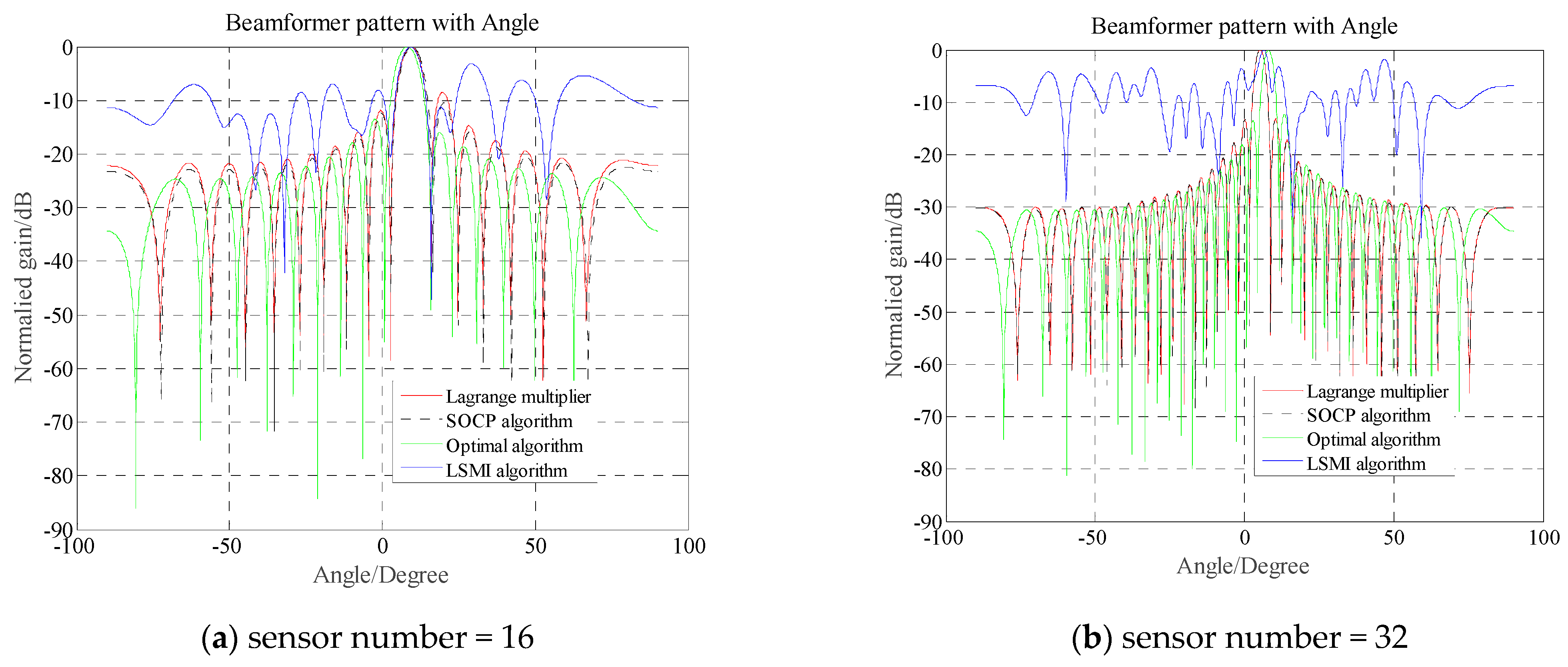
Figure 2. Array angular resolutions of different methods when the uncertain radius is 3.5.
Signals 06 00055 g002
  • Comparison of the performance of Equations (16) and (21). To verify the effectiveness of (16), we perform a simulation using (21) with the same signals and array manifolds as those used in (16). The simulation results are shown in Figure 3a,b. By comparing Figure 1a and Figure 3a with Figure 1b and Figure 3b, respectively, they had the same performance characteristics. In particular, Equation (16) can approximately substitute Equation (21) for the design of robust adaptive beamforming.
Figure 3. Relationship between output SINR of array and input SNR when the uncertain set radius was 3.5. Figure 3a,b was produced using Equation (21) in iteration.
Signals 06 00055 g003

4.2. Computation-Complexity Analysis

In this subsection, we first perform a computational complexity analysis, and then conduct a simulation for testing.
Theoretical computational complexities of the three algorithms are as follows:
(1)
SOCP employs an interior-point approach with a computational complexity of approximately O ( ln ( 1 / δ ) v N 3 ) [17]. The convergence control parameter δ = 10−8. The parameter v denotes the number of independent variables in the constraints, which is equal to the number of array elements N in this study. Therefore, the computational complexity is O ( 18 N 3.5 ) .
(2)
The computational complexity of the proposed formula was determined using A, B, and C. The computational complexity of t r ( R )  is  O ( N 3 ) , and that of a H R 2 a  is O ( 2 N 2 + N ) . Therefore, the computational loads for B, C, and A are O ( 2 N 3 + N 2 ) , O ( N 3 + 2 N 2 + N )  and O ( N ) , respectively. The complexity of this formula is known as O ( 3 N 3 + 5 N 2 + N ) = O ( 3 N 3 ) .
(3)
The computational load of LSMI is O ( N 3 ) + O ( N 2 ) + O ( N ) = O ( N 3 ) .
Therefore, the computation complexity of the SOCP is much greater than that of (16) while the complexity of (16) is three times that of the LSMI. Table 1 presents a numerical example.
The simulation is time-consuming. Computer CPU time was used as the standard for comparing the algorithms. The hardware used for the simulations was a personal computer with i7-11700 @ 2.50 GHz, 2496 MHz, eight cores, 16 logical processors, and Windows 10. The algorithms were programmed using MATLAB v2014b, and the SOCP algorithm was implemented using CVX 2014 in MATLAB. The computation times of the three algorithms are listed in Table 2. Table 2 indicates that the implementation of the Lagrange multiplier method for the WCPO and the diagonal loading method has a computation time of the same order of magnitude; however, the second-order cone method for the WCPO is more than three orders of magnitude slower than the Lagrange multiplier method.
As shown above, both the Lagrange multiplier multiplexer and SOCP offer significant advantages in optimizing the WCPO problem for SINR and DOA estimation. However, the diagonal loading technology performed worse than the other two methods in optimizing the WCPO performance, particularly in the DOA estimation. In terms of computational efficiency, the Lagrange multiplier and DL methods have comparable computation times, which are significantly shorter than those required by SOCP.
Note that differences in the implementation details of these algorithms, such as optimization algorithms and hardware capabilities, can influence their results, although the proposed method demonstrates a significant reduction in computational time compared with the SOCP method. Future studies should aim to standardize these factors for a fair comparison.

4.3. Feature Analysis and Comparison of Beamformers

To study the characteristic differences between the three algorithms for addressing the WCPO problem, this section uses the signal spectrum analysis method to study the amplitude spectrum structures of the three beamformers. The Fourier transforms of the weight vectors associated with the four beamformers are shown in Figure 4.
As shown in Figure 4, the Fourier amplitude spectra of the beamforming filters obtained by the Lagrange multiplier and SOCP methods have the same frequency distribution structure as that of the ideal OPT method, and the Fourier amplitude spectrum of the LSMI (DL) is different.

5. Discussion

In previous sections, we investigated robust adaptive beamforming for WCPO scenarios by studying the Lagrange multiplier closure formula. Assuming a high-SNR single-plane wave incident array, we derive the Lagrange multiplier closure formula in (16). Subsequently, under the assumption of multiple plane-wave irradiation arrays, we formulated the general Lagrange solution Formula (21) for practical applications. Although the Lagrange solution Formula (21) for multiplane waves aligns with real-world scenarios, it requires iterative solving as a function of λ. The single-plane wave Formula (16), derived through a low-rank approximation, demonstrates lower computational complexity than the interior point-based SOCP algorithms. Computer simulations revealed that Formula (16) achieves a performance comparable to that of SCOP algorithms while requiring significantly less computation. The simulation results indicate that Equations (16) and (21) exhibit a similar SINR performance. This demonstrates that Equation (16) can replace Equation (21) under specific engineering approximations, thereby reducing the computational demands. Note that the simulation of the solution-seeking problems was conducted on a personal computer using MATLAB 2014, which may introduce limitations related to computational and software resources. This issue requires further theoretical analyses and parallel algorithm validation through simulations.

6. Conclusions

This study addresses the optimization of the performance in the worst-case scenario for far-field narrowband signals illuminating a uniform linear array. Starting with a single plane wave, this study uses low-rank approximation theory to approximate the correlation matrix of multiple fast snapshots as a rank-1 Hermitian matrix, which can be decomposed into the outer product of two vectors. This approach provides a closed-form solution for Lagrange multipliers for studying robust beamforming in the WCPO problem. In practical scenarios, multiple plane-wave signals (including interference) are observed. We expanded the closed-form formula to (21), which is suitable for the application conditions, except for the limitation of implicit functions. In the simulations, one expected signal and two interference signals were used to test and verify the closed-form solutions with 16 and 32 sensors, respectively. Computer simulations have shown that the results derived from this assumption can be applied to multiplane-wave problems to a certain extent. The beamformer obtained by calculating the Lagrange multipliers using this formula exhibits a similar SINR and incoming wave estimation performance to those produced by the SOCP method; however, it requires three orders of magnitude fewer computations than the latter. In addition, the computational time of the former was comparable to that of the DL method, but its performance surpassed that of the DL method. This method provides a valuable reference for implementing robust real-time beamforming.

Author Contributions

Conceptualization, T.P.; methodology, T.P.; software, T.P.; validation, T.P.; B.P.; formal analysis, T.P.; investigation, T.P.; data curation, T.P.; B.P.; writing—original draft preparation, T.P.; writing—review and editing, T.P.; B.P.; supervision, T.P.; B.P.; project administration, B.P.; funding acquisition B.P. All authors have read and agreed to the published version of the manuscript.

Funding

This research was funded by the Natural Science Foundation of Fujian Province, grant number 2023J011801 and 2023J011804.

Data Availability Statement

The authors confirm that all data generated or analyzed during this study are included in this paper.

Conflicts of Interest

The authors declare no conflicts of interest.

Abbreviations

The following abbreviations are used in this manuscript:
WCPOWorst-case performance optimization
SOCPSecond-order cone programming
DOADirection-of-arrival
SINRSignal-to-interference-plus-noise ratio

References

  1. Khabbazibasmenj, A.; Vorobyov, S.A.; Hassanien, A. Robust adaptive beamforming based on steering vector estimation with as little as possible prior information. IEEE Trans. Signal Process. 2012, 60, 2974–2987. [Google Scholar] [CrossRef]
  2. Zhang, P.; Yang, Z.; Jing, G.; Ma, T. Adaptive beamforming via desired signal robust removal for interference-plus-noise covariance matrix reconstruction. Circuits Syst. Signal Process. 2021, 40, 401–417. [Google Scholar] [CrossRef]
  3. Li, W.; Qu, X.; Yang, X.; Han, B.; Zhang, Z.; Fathy, A.E. Robust adaptive beamforming method based on steering vector phase correction and covariance matrix reconstruction. IEEE Commun. Lett. 2024, 28, 193–197. [Google Scholar] [CrossRef]
  4. Li, H.R.; Geng, J.; Xie, J.H. Robust adaptive beamforming based on covariance matrix reconstruction with RCB principle. Digit. Signal Process. 2022, 127, 103565. [Google Scholar] [CrossRef]
  5. Zhang, P.; Yang, Z.; Liao, G.; Jing, G.; Ma, T. An RCB-like steering vector estimation method based on interference matrix reduction. IEEE Trans. Aerosp. Electron. Syst. 2021, 57, 636–646. [Google Scholar] [CrossRef]
  6. Zhang, J.K.; Zheng, Z.; Wang, C. Robust adaptive beamforming based on covariance matrix reconstruction with Gaussian random dimensionality reduction. Circuits Syst. Signal Process. 2024, 43, 6035–6046. [Google Scholar] [CrossRef]
  7. Huang, Y.; Fu, H.; Vorobyov, S.A.; Luo, Z.-Q. Robust adaptive beamforming via worst-case SINR maximization with non-convex uncertainty sets. IEEE Trans. Signal Process. 2023, 71, 218–232. [Google Scholar] [CrossRef]
  8. Mohammadzadeh, S.; Nascimento, V.H.; Lamare, R.C.; Kukrer, O. Covariance Matrix Reconstruction Based on Power Spectral Estimation and Uncertainty Region for Robust Adaptive Beamforming. IEEE Trans. Aerosp. Electron. Syst. 2023, 59, 3848–3858. [Google Scholar] [CrossRef]
  9. Huang, Y.; Zhou, M.; Vorobyov, S.A. New Designs on MVDR Robust Adaptive Beamforming Based on Optimal Steering Vector Estimation. IEEE Trans. Signal Process. 2019, 67, 3624–3638. [Google Scholar] [CrossRef]
  10. Irani, K.H.; Huang, Y.; Vorobyov, S.A. SINR Maximizing Distributionally Robust Adaptive Beamforming. IEEE Trans. Signal Process. 2025, 73, 2542–2557. [Google Scholar] [CrossRef]
  11. Vorobyov, S.A.; Gershman, A.B.; Luo, Z.Q. Robust Adaptive Beamforming Using Worst-Case Performance Optimization: A Solution to the Signal Mismatch Problem. IEEE Trans. Signal Process. 2003, 51, 313–324. [Google Scholar] [CrossRef]
  12. Lorenz, R.G.; Boyd, S.P. Robust Minimum Variance Beamforming. IEEE Trans. Signal Process. 2005, 53, 1684–1696. [Google Scholar] [CrossRef]
  13. Liao, B.; Chan, S.C.; Tsui, K.M. Recursive Steering Vector Estimation and Adaptive Beamforming under Uncertainties. IEEE Trans. Aerosp. Electron. Syst. 2013, 49, 489–500. [Google Scholar] [CrossRef]
  14. Zhang, P.; Yang, Z.W.; Jing, G. Further study on the RCB-like steering vector estimation method: Closed-form solution derivation via accurate Lagrange multiplier calculation. Signal Image Video Process. 2025, 19, 122. [Google Scholar] [CrossRef]
  15. Yin, J.; Wang, S.; Wang, H. A robust adaptive beamforming method based on variable constraint set. Acta Acust. 2021, 46, 871–883. (In Chinese) [Google Scholar]
  16. Trees, H.L. Optimum Array Processing; Wiley: Hoboken, NJ, USA, 2002; pp. 453–470. [Google Scholar]
  17. Tunçel, L. Polynomial Path-Following Algorithms for Linear and Convex Programming; Princeton University Press: Princeton, NJ, USA, 1999; pp. 89–95. [Google Scholar]
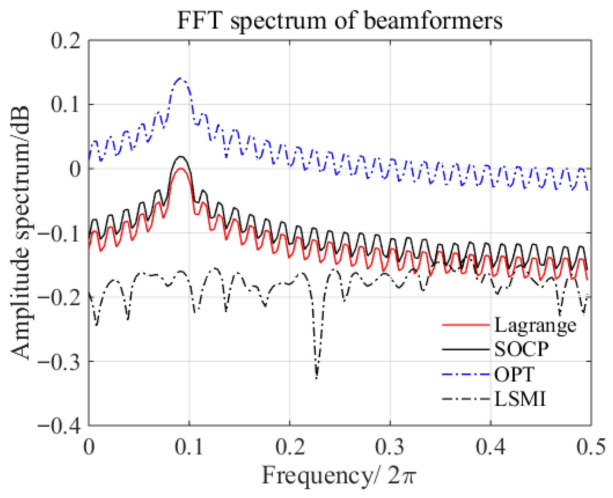
Figure 4. FFT feature of the beamforming weight of Lagrange multiplier, SOCP, OPT and LSMI.
Signals 06 00055 g004
Table 1. Computational complexity comparison of SOCP, LSMI, and Equation (16).
AlgorithmSensor Num. = 16Sensor Num. = 32Sensor Num. = 64
Operators/SOCP
Operators/LSMI
Operators/Proposed formula
  • 294,912
  • 4096
  • 13,584
4.
3,336,549
5.
32,768
6.
103,456
7.
37,748,736
8.
262,144
9.
806,976
Table 2. Computer time for various algorithms with different numbers of sensors.
AlgorithmsSOCP/sLSMI/sLagrange Multiplier/s
16 sensors165.093750.015630.14063
32 sensors323.031250.515630.20313
48 sensors325.109380.250001.07813
64 sensors1233.796881.484381.59375
Disclaimer/Publisher’s Note: The statements, opinions and data contained in all publications are solely those of the individual author(s) and contributor(s) and not of MDPI and/or the editor(s). MDPI and/or the editor(s) disclaim responsibility for any injury to people or property resulting from any ideas, methods, instructions or products referred to in the content.