Article

On the Impulse Response of Singular Discrete LTI Systems and Three Fourier Transform Pairs

Department of Electrical and Computer Engineering, Miami University, Oxford, OH 45056, USA
Signals 2024, 5(3), 460-473; https://doi.org/10.3390/signals5030023
Submission received: 6 May 2024 / Revised: 19 June 2024 / Accepted: 2 July 2024 / Published: 9 July 2024

Abstract

:
A basic tenet of linear invariant systems is that they are sufficiently described by either the impulse response function or the frequency transfer function. This implies that we can always obtain one from the other. However, when the transfer function contains uncanceled poles, the impulse function cannot be obtained by the standard inverse Fourier transform method. Specifically, when the input consists of a uniform train of pulses and the output sequence has a finite duration, the transfer function contains multiple poles on the unit cycle. We show how the impulse function can be obtained from the frequency transfer function for such marginally stable systems. We discuss three interesting discrete Fourier transform pairs that are used in demonstrating the equivalence of the impulse response and transfer functions for such systems. The Fourier transform pairs can be used to yield various trigonometric sums involving s i n π k / N s i n π L k / N , where k is the integer summing variable and N is a multiple of integer L.

1. Introduction

A linear time-invariant (LTI) system is sufficiently described by the unit impulse response function (IRF). Given an LTI system with an unknown IRF, we can use any input function to obtain the IRF. A conceptually simple way to determine a system’s IRF is to use a unit impulse and unit step function as input. However, as a unit impulse has an infinitely short duration and a unit step function has an infinitely long duration, they are not always practical to produce in reality. A more practical and convenient input test function is the rectangular function. For a discrete system, this corresponds to a sequence of uniform pulses. For example, let us have the input to a discrete LTI system as x 1 [ n ] = { 1 ,   n = 0 ,   1 0 ,   o t h e r w i s e and the corresponding output is y 1 [ n ] = { 1 ,   n = 0 ,   1 ,   2 0 ,   o t h e r w i s e . It can be seen that the IRF is h [ n ] = [1, 0, 1, −1, …], which is an infinite sequence with the repeating pattern underlined. For an LTI system, the standard method to find the system’s IRF is to inverse Fourier transform the frequency transfer function H [ k ] = Y [ k ] / X [ k ] , where X [ k ] and Y [ k ] are the discrete Fourier transform (DFT) of the input and output sequences, respectively. In this example, however, inverse discrete Fourier Transform (IDFT) cannot be applied since a singularity (pole) exists. In this article, we are largely concerned only with the singular frequency transfer function (SFTF) of marginally stable systems. In general, deconvolution via IDFT is not doable for SFTF and part of the information is considered lost [1].
To be more general, let the input sequence x [ n ] have L consecutive unit impulses, i.e., x n = 1 ,   0 n L 1 0 ,   n L . The corresponding output of an LTI system is a sequence of real values, y [ n ] . The last non-zero value in y [ n ] occurs at index L y 1 , i.e., y n = 0 ,   n L y and y n 0 for n = L y 1 . In this study, we are confined to finite L and L y . To find the IRF, h [ n ] , we can carry out a time-domain deconvolution via polynomial division or a recursive sum (e.g., [2,3]). Alternatively, the IRF for the above defined x [ n ] can be found through the convolution sum y n = m = 0 h m x n m as
h n = y n y n 1 ,             0 n L 1 y n y n 1 + h n L ,       n L .
Since y n = 0 for n L y , h L y + 1 = h [ L y L + 1 ]. h [ n ] becomes periodic with a period of L starting at m a x ( L y L + 1 ,   0 ) or sooner, where max is the maximum operator. The number of independent points in h [ n ] is M = m a x ( L y + 1 ,   L ) . h [ n ] can alternatively be expressed as
h n = m = 0 L y 1 y m q n m + h n L u n L ,
where q m = 1 ,   m = 0 1 ,   m = 1 0 ,   o t h e r w i s e   , and u m = 0   m < 0 1   m 0   is the unit step function. In general, such an LTI system has an infinite IRF.
Fundamental to LTI systems is that they are sufficiently described by either h [ n ] or its Fourier transform, the frequency transfer function H [ k ] (e.g., [3,4]). If h [ n ] and H [ k ] are indeed equivalent in characterizing an LTI system, a logical conclusion is that we can always obtain one from the other. The fact that we cannot find h [ n ] from a singular H [ k ] via IDFT may not be because H [ k ] has incomplete information but because we have not found the right way to carry it out. Otherwise, we have to admit H [ k ] and h [ n ] are not always equivalent. The problem appears to be simple and yet fundamental to LTI systems. Although LTI theory is very mature, obtaining IRF from an SFTF has not received much attention. Despite extensive searches in the Web of Science database and the open internet, the author cannot find any references on the direct conversion from SFTF to IRF. There are possibly two reasons for this: (1) we cannot apply DFT or IDFT when there are singularities; (2) alternative ways, such as polynomial division, can be used to obtain h [ n ] . General discussions on the zeros of the discrete-time system can be found in [5,6]. The stability of fractional oscillators is analyzed by Li et al. [7]. Schluter and Darup [8] showed that linear dynamic controllers with integer coefficients are usually unstable. Park et al. [9] discussed uniformly marginally stable zeros of linear sampled data systems and its application to stable inversion-based control. In the following, we demonstrate that we can recover h [ n ] from H [ k ] when X [ k ] , the DFT of the input function, is a sinc function.
To describe the problem more precisely, let us consider the details of H [ k ] . To perform the discrete Fourier transform (DFT), we zero-pad x [ n ] and y [ n ] to N elements. Let X [ k ] and Y [ k ] be the DFT of the zero-padded sequence of x [ n ] and y [ n ] , respectively. The N -point DFT of x [ n ] is defined as
X k n = 0 N 1 x n e j 2 π n k / N ,   k = 0     N 1 .
In this article, we restrict our input to x n = 1 ,   0 n L 1 0 ,   L n N 1 . For k N = 0 ,   1 ,     N 1 , we have
X k = n = 0 L 1 e j 2 π n k N = 1 W k L 1 W k = W L 1 k / 2 s i n π N L k s i n π N k .
where π N = π N and W = e j 2 π N . X k has zeros at k = l N L , where l 1 , , L 1 . We denote the set of the zeros of X k as k o = N L , L 1 N L . Denoting Y k as the N -point DFT of y n , i.e., Y k = n = 0 L y 1 y n W n k , k N , the frequency transfer function is thus
H k = Y k X k = Y k 1 W k 1 W k L .
The poles, which characterize the stability of a system, are at ko, which are all on the unit cycle in the corresponding Z -transform and H 0 = Y 0 / L . Such a system is considered to be marginally stable [10]. IDFT cannot be directly performed on H k to obtain h [ n ] when there are singularities.
If we limit our objective to obtain h [ n ] from H [ k ] , we may attempt to avoid poles in H [ k ] . As we are concerned with discrete operations, we can sample H k in such a way that there are no poles. In fact, when N is not divisible by L , H [ k ] does not necessarily have a singularity. In this first approach, the inverse transform, however, does not yield h [ n ] , as shown in Figure 1. In this example, N = 17 ,   L = 3 ,   y [ 0 : 4 ] = 0 , and y [ 5 : N 1 ] = 0 . Alternatively, when N is divisible by L , we can assign a large value at k = k o to attempt for an approximation of h [ n ] . We show an example of this second approach in Figure 2, where N = 16 ,   L = 2 , y [ 0 : 6 ] = 1 ,   y [ 7 : N 1 ] = 0 , and H [ k o ] = 10 10 . The approach does not work in two aspects. The h [ n ] computed from the IDFT method yields values proportional H [ k o ] we artificially set and it is not even proportionally correct at the beginning indices. This invalidates the notion that a large enough real value is a reasonable numerical approximation when there is a zero in the denominator.
In the following, we show that when the input function x [ n ] is a rectangular function and the output y [ n ] is a finite length sequence, h [ n ] can indeed be recovered from X [ k ] and Y [ k ] when N is divisible by L . Before we delve into the proofs, we outline our method of obtaining h [ n ] from H [ k ] in Section 2. The proof of our method is facilitated by three interesting discrete Fourier transform pairs, which are discussed in Section 3. Each of the three DFT pairs is presented as a lemma. Section 4 contains the proof of our method and we point out some potential questions to be explored further in Section 5.

2. Summary of the Solution

Let N be divisible by L throughout the following discussion, and we define
Z k 0 ,                                                  k k o   1 W k 1 W k L = e j π N L 1 k s i n π N k s i n π N L k ,      k k o ,
and H 1 k Y k Z k . H 1 k sets the poles of H k to zeros but otherwise is the same as H k . Let the N-point IDFT of H 1 k be h 1 n , i.e.,
h 1 n 1 N k = 0 N 1 H 1 k W n k .
From h 1 n , we obtain h 2 n as
h 2 n h 1 n + h 1 n + L l ,
where L l = i n t L y L L , with i n t being the integer operator. We construct h 3 k in the following manner:
h 3 n   h 2 n h 2 N h + n ,                                      N = 2 m L h 2 n h 2 n + N h L h + h 2 n + N h + L L h 2 ,        N = 2 m + 1 L   ,
where m is a positive integer, L h = i n t L 2 , and N h = i n t N 2 . Alternatively, h 3 n can be computed via the following operation:
h 3 n =   2 N m = 0 L y 1 y m k = 1 ,   o d d N 1 F 1 k ,   m n ,               N = 2 m L   1 N m = 0 L y 1 y m k = 1 N 1 ,    k o F 2 k ,   m n   ,          N = 2 m + 1 L  
where F 1 ( k , n ) W n k Z k 1 + W L l k and F 2 ( k , n ) F 1 ( k , n ) [ 1 e j π k cos π N L k ] . Finally, we duplicate h 4 n from h 3 n and make the following modifications:
h 4 n h 3 n + h 4 n M 1 , h 3 n + ( h 4 n M 2 + h 4 n M 2 L ) / 2   M 1   n N h 1 ,     N = 2 m L   M 2 n N h 1 ,     N = 2 m + 1 L
where M 1 = N h L l , M 2 = N h L l , and N h = N L 2 . ( h 4 n = 0 if n < 0 ).
In the following, we demonstrate that when N   2 L y + 1 , h 3 n = h n for n < N 2 L l if N = 2   m L , and h 3 n = h n for n < N L 2 L l if N = ( 2   m + 1 ) L . We further demonstrate h 4 n = h n for n < N / 2 if N = 2   m L . In the next section, we present three Fourier transform pairs that are used for the proofs.

3. Three Fourier Transform Pairs and Their Properties

3.1. Inverse Fourier Transform of Z 0 [ k ] and Properties of h 1 n

Defining Z 0 k Z [ k ] ( 1 δ k ) , we can rewrite h 1 n , defined by (7), as
h 1 n = 1 N L m = 0 L y 1 y m + 1 N m = 0 L y 1 y m q 0 n m ,
where
q 0 m k = 0 N 1 W m k Z 0 k = k = 1 N 1 W m k Z k ,
i.e., q 0 m and Z 0 k = Z [ k ] ( 1 δ k ) form a DFT pair. In (7a), the index of q 0 can be negative. Noting that W m N = 1 and Z k = Z * N k , where * is for complex conjugate, q 0 m can be alternatively expressed as follows:
q 0 m = 1 2 k = 1 N 1 ( W m k Z k + W m ( N k ) Z [ N k ] ) = k = 1 N 1 ,    k o cos π N ( 2 m + L 1 k ) sin π N k sin π N L k .
As q 0 m and y [ n ] are real, h 1 n is thus real as well. Since q 0 m is an IDFT, all the DFT/IDFT properties apply, including the periodicity property, q 0 m = q 0 N + m .
Lemma 1.
If  N  is divisible by  L ,
q 0 m = N h m % N δ m ,   L N h m % N + 1 δ m 1 , L ,
where  N h = N L 2 ,  m % N = m o d ( m ,   N )  is  m  modulo  N ,  δ m , L 1 ,   i f   f   m L I   0 ,   o t h e r w i s e  is the comb function with a period of L, and  I  is the set of all integers.
Proof. 
Equation (11) can be written as
q 0 m = i = 1 : N / L   N 1 W m k 1 W i 1 W i L + i = 2 : N / L   N 1 W m k 1 W i 1 W i L + + i = N / L 1 : N / L   N 1 W m k 1 W i 1 W i L ,
where i = 1 : N / L N 1 indicates that the summation starts at i with an incremental of N / L and ends at a value up to but not larger than N 1 . Since W i L = W N / L + i L for i l , the denominator in each summation does not vary with the summation index. The above equation can be simplified to
q 0 m = L k = 1   N / L 1 W m k δ m ,   L W m 1 k δ m 1 , L 1 W L k .
If m is divisible by L and for m N , we have
q 0 i + 1 L q 0 i L = L ,    N 1 L 1     i   0 .
If m 1 is divisible by L ,
q 0 i L + L + 1 q 0 i L + 1 = L ,    N 2 L 1     i   0 .
Using the fact that W N L = W L , q 0 0 through q 0 L 1 are
q 0 0 = L 2 k = 1   N L 1 ( 1 1 W L k + 1 1 W L N L k ) = N h ,
q 0 1 = q 0 0 = N h ,
q 0 l = 0 ,      1 < l L 1 ,
As q 0 m = q 0 N + m , the recursive Equations (12) and (13) lead to
q 0 m =     N h m % N , m / L I   N h + m % N 1 , ( m 1 ) / L I     0 , o t h e r w i s e
The expression can be alternatively written as Equation (11b). □
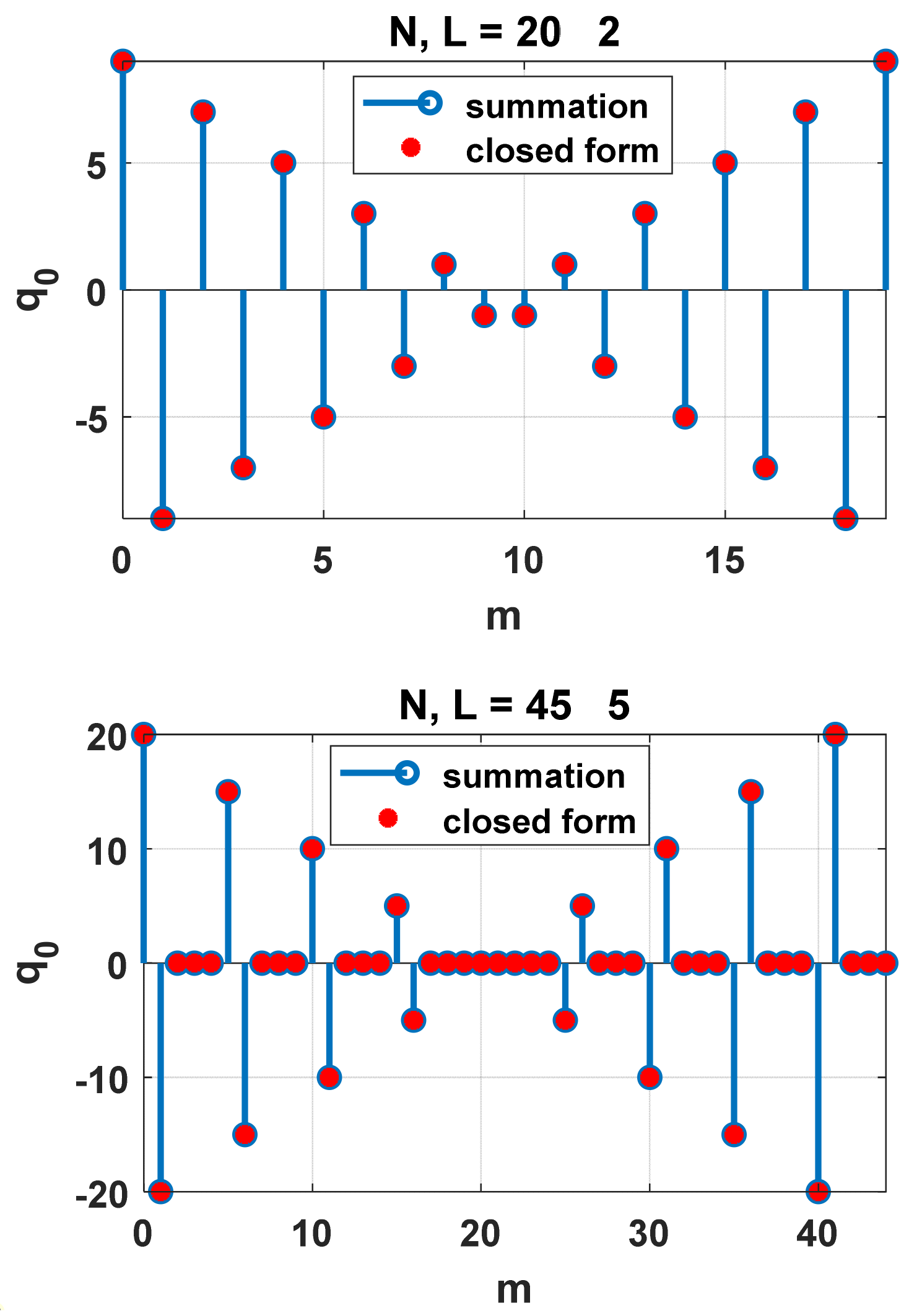
Expression (11b) consists of two linear functions in one period for m = [ 0 ,   N 1 ] . Two example plots of q 0 m expressed as the sum of (11) and the closed form of (11a) are shown in Figure 3 for N = 20 , L = 2 and N = 4   5 , L = 5 . Lemma (1) shows that the sum expressed by Equation (11a), which happens to be the Fourier transform of Z 0 [ k ] , has a simple expression. For instance, letting m = 0 , we have k = 1 N 1 ,   k o cos π N ( L 1 k ) sin π N k sin π N L k = N L 2 . Similarly, letting m = 1 leads to k = 1 N 1 ,   k o cos π N ( L + 1 k ) sin π N k sin π N L k = N L 2 .
Other than being real and periodic, for i , k , m I , q 0 has the following properties:
(i)
m = 0 N 1 q 0 m = m = i : L i + ( N 1 ) q 0 m = 0 ;
(ii)
q 0 i L + q 0 N L i L = 0;
(iii)
q 0 i L = q 0 i L + 1 = N h ( i L ) m % N ;
(iv)
q 0 i L + 1 + q 0 N L i L + 1 = 0;
(v)
q 0 i L + q 0 N i L = L + N δ ( i L ) % N ;
(vi)
q 0 i L + 1 + q 0 N i L + 1 = L N δ ( i L ) % N .
Theorem 1.
For  l L = 0 ,   1   L 1 ,  h 1 k L + l  is a linear function of  k  for  k L + l m a x ( L y L + 1 , 0) and  h 1 N 2 0  as  N .
Proof. 
From Lemma 1, (7a) can be expressed as
N h 1 n 1 L m = 0 L y 1 y m = m = 0 L y 1 y m { N h ( n m % N ) δ n m , L N h ( n m % N + 1 ) δ n m 1 , L } .
Letting n 1 = k L + l and n 2 = n 1 + L , we have
h 1 n 2 h 1 n 1 = 1 N m = 0 L y 1 y m   [ n 2 m % N n 1 m % N ] ( δ n 1 m 1 , L δ n 1 m , L ) .
The condition for h 1 k L + l to be a linear function of k is that the above expression is independent of k . This condition is satisfied when n 1 m and n 2 N 1 as n 2 m % N n 1 m % N = L and δ n 1 m 1 , L δ n 1 m , L = δ l m 1 , L δ l m , L . For n 1 < m , the right-hand side summation of (18) is zero if n 1 m 1 L + 1 due to δ n 1 m 1 , L δ n 1 m , L = 0 . If max L y L + 1 , 0 n 1 L y 2 , h 1 2 L + n 1 h 1 L + n 1 = h 1 L + n 1 h 1 n 1 = L N m = 0 n 1 y m ( δ n 1 m 1 , L δ n 1 m , L ) . Combining the cases for n 1 m and n 1 < m proves the first part of the theorem.
When N L + L y is even, we have
N h 1 2 N h + L y 2 1 L m = 0 L y 1 y m = m = 0 L y 1 y m L y 2 + m δ 2 N h + L y 2 m , L + L y 2 m 1 δ 2 N h + L y 2 m 1 , L .
For finite L y and bounded y m , all of the terms in the summation are bounded. As N ,   h 1 N + L y L 2 =   h 1 N 2 0 for even N . When N + L y L or N is odd, the same argument holds when N is replaced by N 1 . This proves the second part of the theorem. □
When N is finite, | h 1 [ n ] | around n = N + L y L 2 is typically smaller than around n = N / 2 . As the periodic linearity starts at L y L + 1 , the middle point of the linear region is at N + L y L 2 , which is the converging point of h 1 n . An example h 1 n is shown in Figure 4. Two additional examples are provided in Section 4.

3.2. Inverse Fourier Transform of Z k δ [ k + 1 , 2 ]

Let q 1 m and Z k δ [ k + 1 , 2 ] be a DFT pair, i.e.,
q 1 m k = 0   N 1    W m k Z k δ k + 1 , 2 = k = 1 ,    o d d N 1    W m k Z k .
Lemma 2.
If  N / L  is an even integer,
q 1 m = N 4 ( δ m , L δ m 1 , L ) b N [ m ] ,
where  b N [ m ] = δ m % N N 2 1 δ m % N N 2 .
Proof. 
q 1 m in one period for m N is
q 1 _ 1 m = N / 4 ,      m = 0 : L : N 2 L ;     N 2 + 1 : L :   N L + 1 N / 4 ,           m = 1 : L : N 2 L + 1 ;     N 2 : L : N L   0 ,                    o t h e r w i s e                                           .
The N -point DFT of q 1 _ 1 m is
Q 1 k = N 4 m = 0 : L N 2 1 ( W m k + W N 2 + 1 + m k W m + 1 k W N 2 + m k ) .
The denominators of the four geometric sums are the same. The sums of the geometric sequences can be reduced to
Q 1 k = N Z k ,     k = o d d      0 ,           k = e v e n
That is, q 1 _ 1 ( m ) and Q 1 k form a DFT pair. The IDFT of Q 1 k recovers q 1 _ 1 m for m N :
k = 1 ,    o d d N 1 W m k Z k = q 1 _ 1 m .
As q 1 m = q 1 N + m , a general expression for q 1 m is Equation (20a), which can be alternatively expressed as
q 1 m = ( δ m c m , L δ m 1 + c m , L ) N / 4 ,
where c m = i n t 2 N m % N = 1 b N m 2 . □
Lemma 2 can also be proven by following the approach used in proving Lemma 1. Like q 0 m , q 1 m is real and periodic. Additional properties of q 1 m include
(i)
m = 0 N 1 q 1 m = m = i : L i + ( N 1 ) q 1 m = 0 ;
(ii)
q 1 m = q 1 N L + 1 m ;
(iii)
q 1 i L = q 1 i L + 1 = N 4 b N [ i L ] ;
(iv)
q 1 m = q 1 N 2 + m .
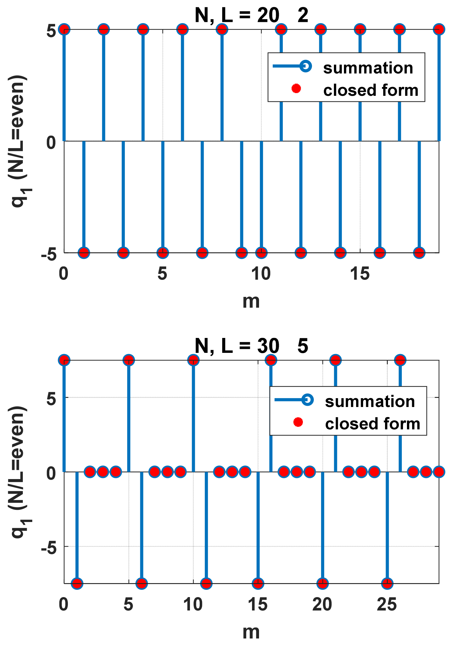
Following (11a), q 1 m can be expressed as q 1 m = k = 1 ,   o d d N 1 ,   k o cos π N ( 2 m + L 1 k ) sin π N k sin π N L k . Lemma 2 shows that this sum of trigonometric functions has only three possible values. For example, k = 1 ,   o d d N 1 ,   k o cos π N ( L 1 k ) sin π N k sin π N L k = N 4 , and k = 1 ,   o d d N 1 ,   k o cos π N ( L + 1 k ) sin π N k sin π N L k = N 4 . Two example plots for q 0 [ m ] are shown in Figure 5 for N = 20, L = 2 and N = 30, L = 5.

3.3. Inverse Fourier Transform of 1 e j π k cos π N L k Z k

We define
q 2 m k = 0 N 1 W m k 1 e j π k cos π N L k Z k                 = k = 1 N 1 W m k 1 e j π k cos π N L k Z k ,
i.e., q 2 m and 1 e j π k cos π N L k Z k form a DFT pair.
Lemma 3.
If  N / L  is an odd integer,
q 2 m = N 2 δ m , L δ m 1 , L δ m % N < N h N 2 ( δ m N h + , L δ m N h + 1 , L ) δ [ m % N N h + ] ,
where  N h + = N + L 2  and  N h = N L 2 .
Proof. 
As in the proof for Lemma 2, we take the N-point DFT of q 2 m as expressed by Equation (23a) for m N
Q 2 k = N 2 m = 0 : L N 2 L ( W m k + W N h + + 1 + m k W m + 1 k W N h + + m k ) .
The sums of the geometric sequences can be reduced to
Q 2 k = N Z k 1 e j π k c o s ( π N L k ) , k k o 0 , k = k o   .
As Z k o = 0 , the above equation can be simply written as
Q 2 k = N Z k 1 e j π k c o s ( π N L k ) .
The IDFT of Q 2 k leads back to Equation (23a) for m N , i.e.,
k = 0 N 1 W m k 1 e j π k cos π N L k Z k = N 2 ,     m = 0 : L : N L 2 L ;   N h + + 1 : L : N L + 1   N 2 ,      m = 1 : L : N L 2 L + 1 ;    N h + : L : N L   .      0 ,                               o t h e r w i s e                                    
Note that q 2 N h = q 2 N h + 1 = 0 . Since q 2 m = q 2 N + m , a more general expression for any m is Equation (23a). Alternatively, we can express Equation (23a) as
q 2 m = N 2 [ δ ( m c m N h + c m , L ) δ ( m + c m 1 N h + c m , L ) ] ,
where c m = δ m % N N h + + 1 2 δ ( m % N = N h ) ( m % N = N h + 1 ) . In this expression, we have assigned c m = 1 / 2 at m % N = N h or m % N = N h + 1 to make q 2 m zero at these two points. Analogous to Equation (20a), Equation (23a) can also be written as
q 2 m + N + L 2 = N 2 ( δ m , L + δ m 1 , L ) b N [ m ] ,
where b N [ m ] = δ m % N N h 1 δ N 2 L + 1 m % N N h . □
Other than the fact that q 2 is real and periodic, additional properties include the following:
(i)
m = 0 N 1 q 2 m = m = i : L i + ( N 1 ) q 2 m = 0 , i I ;
(ii)
q 2 m = q 2 N L + 1 m ;
(iii)
q 2 i L + q 2 i L + 1 = 0 .
Note that q 2 m = 2 q 1 m for 0 m   L ( m i n ( N 1 2 , N 2 L 2 ) 1 ) , where N 1 and N 2 are used to generate q 1 m and q 2 m , respectively, and m i n is the minimum operator. Like q 1 [ m ] , q 2 [ m ] has only three values. The lengthiness in Expression (23a) is to account for the positions of the three values. The number of positive values in q 1 per period is N / L , while there are N / L 1 positive values in q 2 per period. Similar to Lemmas 1 and 2, Lemma 3 can also be used to find sums containing s i n π k / N s i n π L k / N . Two example plots of q 2 [ m ] are shown in Figure 6 for N = 18, L = 2 and N = 25, L = 5.

4. Equivalence to the Unit Impulse Response Function

4.1. Relationship of h 3 [ n ] and h 2 [ n ] with h [ n ]

Theorem 2.
If  N   2 L y + 1 ,  h 3 n = h n  for  n < N 2 L l    when  N L  is even; and  h 3 n = h n  for  n < N L 2 L l    when  N L  is odd.
Proof. 
Case 1: N L is an even integer.
From the definition of h 1 n and h 2 n , we have
h 2 n + N 2 = 2 N L m = 0 L y 1 y m + 1 N m = 0 L y 1 y m k = 0 N 1 F 1 k ,   m n e j π k
From Equation (9) and Lemma 2, we have
h 3 n = 2 N m = 0 L y 1 y m ( q 1 n m + q 1 n + L l m ) .
The minimum value for n m is L y + 1 . When n + L l m < 0 , q 1 n + L l m ) = q 1 N + n + L l m = 0 since N + n + L l m N L + 2 . q 1 n m = q 1 n + L l m = 0 under the condition that N 2 L y 1 . When n + L l m 0 and n m < 0 , q 1 n m = q 1 N + n m = q 1 N 2 + n m = q 1 n + L l m under the condition that N 2 L y + 1 . Thus, when n m < 0 , q 1 n m + q 1 n + L l m = 0 if N 2 L y + 1 . When n m 0 and n + L l < N 2 , q 1 n m = q 1 n + L l m as L l is zero or a multiple of L . Thus,
h 3 n = 4 N m = 0 L y 1 y m q 1 n m = m = 0 L y 1 y m q n m + h n L u n L
This is the same as Equation (2). Therefore, if N 2 L y + 1 , h 3 n = h n for n < N 2 L l .
In order to produce M points (corresponding to index n = 0 : M 1 ) accurately in h 3 [ n ] , the minimum N required is N m i n = 2 m a x ( L y + 1 , L ) + 2 L y 2 m o d ( L y , L ) 1 . For example, if L y = 4 , L = 3 , N m i n = 4 L y 1 = 15 . Since N / L needs to be an even integer, N should be 18 to authentically produce the first five elements.
Case 2: N L is an odd integer
Similar to Case 1 and applying Equation (10) for odd N / L and Lemma 3, h 3 n can be written as
h 3 n = 1 N m = 0 L y 1 y m ( q 2 n m + q 2 n + L l m ) .
Using the same process as in case 1, h 3 n can be shown to be identical to h [ n ] for n < N L 2 L l and N   2 L y + 1 . □
Corollary 1.
h 2 n h n  for finite  n  as  N .
Proof. 
For finite L and L y , h 2 n = h 3 n + h 2 n + N h = h n + h 1 n + N h + h 1 n + N h + L l as N for finite n . From Lemma 1, h 1 n + N h = h 1 n + N h + L l = 0 for finite n and L l . Thus, h 2 n h n for finite n as N . The corollary states that h 2 n can be a good approximation of h [ n ] if N is sufficiently large. □

4.2. Relationship of h 4 [ n ] with h [ n ]

Theorem 3.
If  N   2 L y + 1  and  N / L  is even,  h 4 n = h n  for  0 n < N 2 .
Proof. 
Let n = k M 1 + n 1 , where M 1 = N / 2 L l , k = i n t ( n / M 1 ) , and n 1 = m o d ( n , M 1 ) . The recursive Equation (10) for even N / L can be written as
h 4 [ n ] = i = 0 k h 3 [ n 1 + ( k i ) M 1 ] .
When k = 0 , h 4 [ n ] = h 3 [ n ] = h [ n ] for n < N 2 L l , as demonstrated in Theorem 2. We just need to consider k 1 and N 2 L l n < N 2 in the following. Note that m o d ( n 1 + ( k i ) M 1 , L ) = m o d ( n 1 , L ) for all integer k and n 1 . Using property (iv) of q 1 [ n ] and Equation (27), the above summation results in
h 4 n = 2 N m = 0 L y 1 y m ( q 1 n m + q 1 n 1 + L l m ) .
When n 1 + L l m < 0 , q 1 n 1 + L l m = 0 as n 1 + L l m > L + 2 , which makes q 1 n m = 0 . When n 1 + L l m 0 and n m < 0 , q 1 n m = q 1 n 1 + L l m . When n 1 + L l m 0 and n m 0 , q 1 n m = q 1 n 1 + L l m for n < N / 2 . Thus, for n m 0 and n < N 2 , q 1 n m = q 1 n + L l m , which leads to
h 4 n = 4 N m = 0 L y 1 y m q 1 n m = h [ n ] .
The above is the same equation as (25a) except the applicable range for n is improved to n < N / 2 . □
When N L is an odd integer and n N h 1 , the following recursive equation appears to be true:
h 4 [ n ] = h 3 n + ( h 4 n N h + L l + h 4 n N h + L l L ) / 2 .
However, the author is unable to obtain a proof at this point.

4.3. Examples

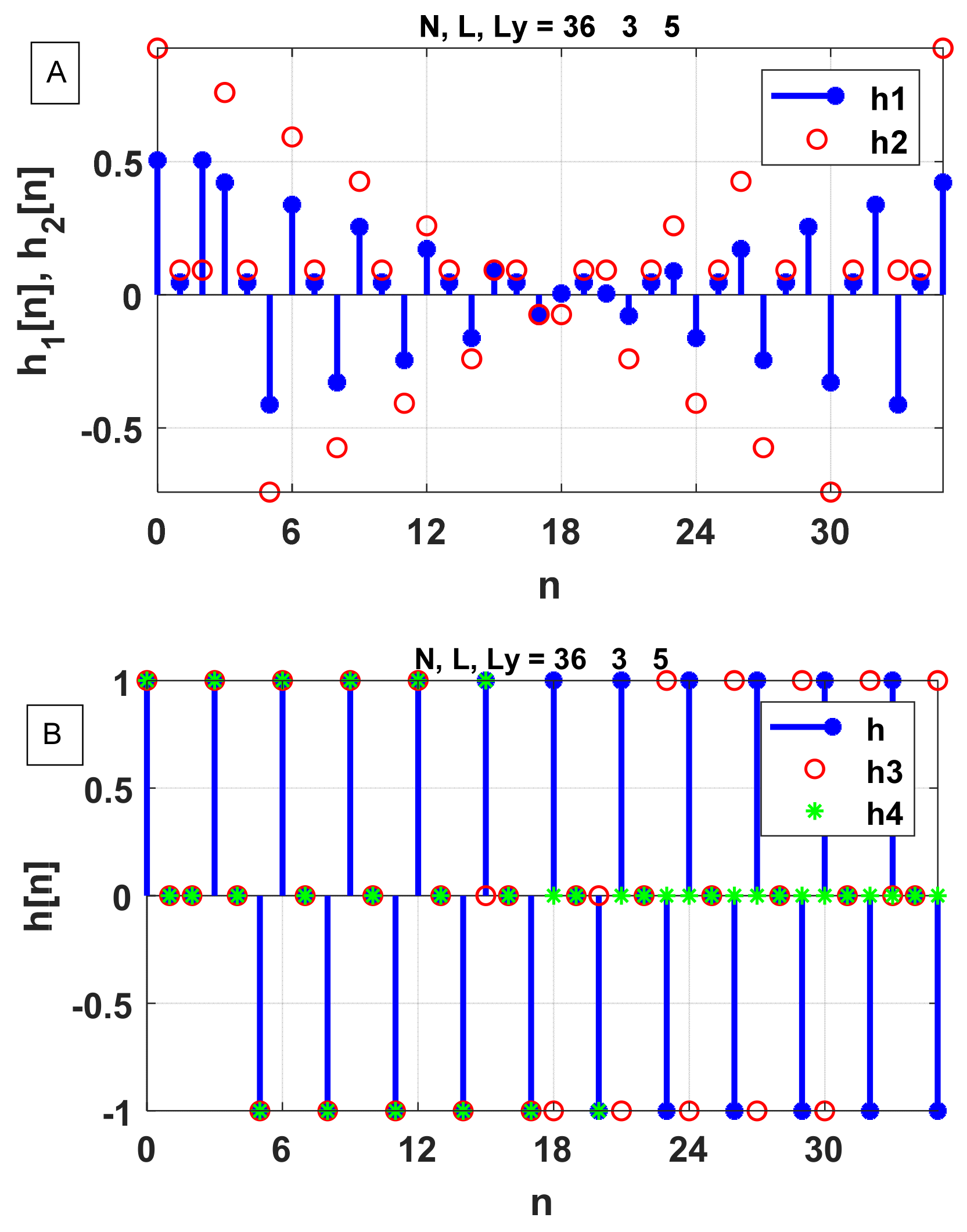
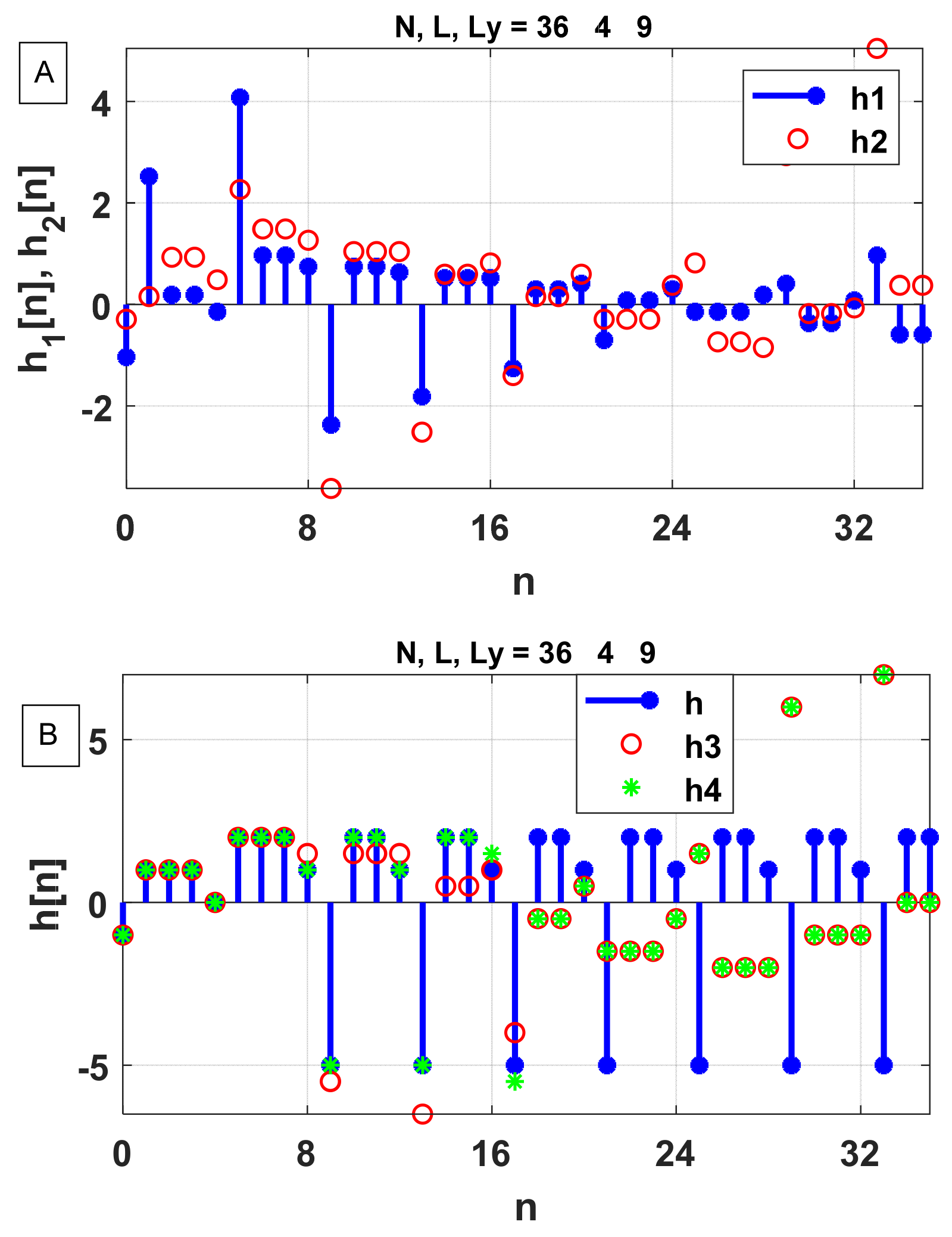
In our first example ( N / L is even), input x n = 1 ,   0 n 2 0 ,   3 n N , and output y n = 1 ,   0 n 4 0 ,   5 n N , with N being 36. h 1 n and h 2 n are plotted in Figure 7A, while h 3 n and h 4 n are plotted along with the true impulse response function, h n , in Figure 7B. As seen in Figure 7A, h 1 n starts to be periodically linear at index 3 i . e . ,   L y L + 1 . h 3 n is the same as h n = [1, 0, 0, 1, 0, −1…] for the first N / 2 i n t L y / L L = 15 points and h 4 n is the same as h n for the first N / 2 = 18 points in agreement with the above discussion. In the second example ( N / L is odd), the input is x n = 1 ,   0 n 3 0 ,   4 n N , and the output is y n = n 1 ,   0 n 8 0 ,   9 n N , with N = 36 . The impulse response function for this system is h [ n ] = [−1, 1, 1, 1, 0, 2, 2, 2, 1, −5, …], with the periodic oscillations starting after six data points. The periodic linearity for h [ n ] starts at index 6, as seen from Figure 8A. As indicated in Figure 8A, h 3 n is the same as h [ n ] for the first ( N L ) / 2 i n t ( L y / L ) L = 8 data points. In this case, N is not large enough for h 3 n to obtain all 10 independent points in h [ n ] . h 4 n , which is computed from Equation (29), is the same as h [ n ] for the first N L 2 1 = 15 points. In Figure 9, we show an example of relatively large L (80) and Ly (149) with N = 4 L . The output sequence, y [ n ] , is an integer array consisting of randomized numbers from 1 to 149. h 4 n is the same as h [ n ] for the first N 2 = 160 points, while h 4 n equals h [ n ] for the first N 2 L l = 80 points.

5. Conclusions

The frequency transfer function, H [ k ] , of a linear time-invariant system is generally considered to be equivalent to the unit impulse response function h [ n ] . The normal process of obtaining the impulse function from the frequency transfer function via the DFT, however, breaks down when the latter has singularities for discrete systems. This happens when the input time-domain function is a uniform train of pulses and the transfer function contains zeros on the unit cycle. We show that the frequency transfer function contains complete information to determine the IRF in such a case. A broader fundamental question to be answered is whether the IRF can always be determined from a frequency transfer function containing singularities. If the answer is positive, the ensuring question is how to find h [ n ] from H [ k ] with any kind of pole in general.
Our method to obtain h [ n ] from H [ k ] involves performing the inverse Fourier transform of the transfer function by excluding the poles to obtain a time-domain function, h 1 n . We show that a linear combination of h 1 n and its shifts can yield h [ n ] . It is important to note that the poles in the transfer function discussed here are all on the unit circle in the z-domain. Such systems are marginally stable and h [ n ] is periodic after m a x ( L y L + 1 ,   0 ) points. The number of independent points in h [ n ] , M , is the larger of L y + 1 or L . Our method requires the length of the discrete transfer function, N , to be at least 2 M to correctly capture the first M points in h [ n ] . It is of interest to explore whether it is possible to obtain the first M points of h [ n ] using N < 2 M .
In demonstrating that h [ n ] can be obtained using the DFT method, we have explored three interesting Fourier transform pairs. These DFT pairs are used not only for obtaining h [ n ] from H [ k ] but can be used to yield various trigonometric sums involving s i n π k / N s i n π L k / N , where N is a multiple of integer L and k is the summing integer variable.

Funding

The study is partially supported by the U.S. National Science Foundation grant AGS-2152109.

Data Availability Statement

No new data were created or analyzed in this study. Data sharing is not applicable to this article.

Conflicts of Interest

The author declares no conflicts of interest.

References

  1. Press, W.; Teukolsky, S.; Vetterling, W.; Flannery, B. Numerical Recipes: The Art of Scientific Computing, 3rd ed.; Cambridge University Press: Cambridge, UK, 2007; p. 645. [Google Scholar]
  2. Franklin, G.F.; Powell, J.D.; Emami-Naeini, A. Feedback Control of Dynamic Systems, 7th ed.; Pearson: Upper Saddle River, NJ, USA, 2015; p. 617. [Google Scholar]
  3. Proakis, G.G.; Manolakis, D.G. Digital Signal Processing Principles, Algorithms, and Applications, 3rd ed.; Prentice-Hall International, Inc.: London, UK, 1996; pp. 363–365. [Google Scholar]
  4. Oppenheim, A.V.; Willsky, A.; Nawab, S. Signals and Systems; Prentice Hall: New York, NY, USA, 1997. [Google Scholar]
  5. Åström, K.J.; Hagander, P.; Sternby, J. Zeros of sampled systems. Automatica 1984, 20, 31–38. [Google Scholar] [CrossRef]
  6. Blachuta, J. On zeros of pulse transfer functions. IEEE Trans. Autom. Control 1999, 44, 1229–1234. [Google Scholar] [CrossRef]
  7. Li, M.; Lim, S.C.; Chen, S.Y. Exact Solution of Impulse Response to a Class of Fractional Oscillators and Its Stability. Math. Prob. Eng. 2011, 2011, 657839. [Google Scholar] [CrossRef]
  8. Schluter, N.; Darup, M.S. On the stability of linear dynamic controllers with integer coefficients. IEEE Trans. Autom. Control 2022, 67, 5610–5613. [Google Scholar] [CrossRef]
  9. Park, G.; Shim, H.; Hagiwara, T. On existence of uniformly marginally stable zeros of linear sampled-data systems and its application to stable inversion-based control. IEEE Access 2024, 12, 49826–49836. [Google Scholar] [CrossRef]
  10. Nice, N.S. Control Systems Engineering, 6th ed.; John Wiley & Sons, Inc.: New York, NY, USA, 2011; p. 302. [Google Scholar]
Figure 1. An example showing that h [ n ] obtained by IDFT is not correct when N/L is not an integer. Red stems are the results from IDFT, while blue circles represent the true h [ n ] .
Signals 05 00023 g001
Figure 2. An example showing that h [ n ] obtained by IDFT (red) is not correct when H [ k o ] is set to 1010. Note that, in this case, the IDFT results, as indicated by the red symbols, are scaled down by 10−9. Blue circles represent the true h [ n ] values.
Signals 05 00023 g002
Figure 3. Example plots to show that the summation expressed by (11a) is the same as the closed form expressed in (11b). Note that q 0 consists of two linear functions.
Signals 05 00023 g003
Figure 4. An example of h 1 [ n ] . In this example, N = 42, L = 3 and y is a train of 11 contiguous unit impulses.
Signals 05 00023 g004
Figure 5. Example plots to show that the summation expressed by (20) is the same as the closed form expressed in (20a). q 1 has only three possible values.
Signals 05 00023 g005
Figure 6. Example plots to show that the summation expressed by (20) is the same as the closed form expressed in (20a).
Signals 05 00023 g006
Figure 7. The upper panel is for h 1 [ n ] and h 2 [ n ] while the lower panel is for h 3 [ n ] and h 4 [ n ] and the true impulse response, h [ n ] . In this example, N = 36, L = 3 and L y = 5. Note that h [ n ] and h 3 [ n ] are the same for n = 0:14, while h [ n ] and h 4 [ n ] are the same for n = 0:17.
Signals 05 00023 g007
Figure 8. Same as Figure 7 except that, in this example, N = 36, L = 4 and L y = 6. h [ n ] and h 3 [ n ] are the same for n = 0:11, while h [ n ] and h 4 [ n ] are the same for n = 0:15.
Signals 05 00023 g008
Figure 9. An example plot for h [ n ] ,   h 3 [ n ] and h 4 [ n ] with L = 80, Ly = 149 and N = 320. Each element in y [ n ] is a random integer from 1 to 149.
Signals 05 00023 g009
Disclaimer/Publisher’s Note: The statements, opinions and data contained in all publications are solely those of the individual author(s) and contributor(s) and not of MDPI and/or the editor(s). MDPI and/or the editor(s) disclaim responsibility for any injury to people or property resulting from any ideas, methods, instructions or products referred to in the content.