Article

Vibration Suppression of Graphene Reinforced Laminates Using Shunted Piezoelectric Systems and Machine Learning

by
Georgios Drosopoulos
1,2,*,
Georgia Foutsitzi
3,
Maria-Styliani Daraki
4 and
Georgios E. Stavroulakis
4
1
Discipline of Civil Engineering, University of Central Lancashire, Preston PR1 2HE, UK
2
Discipline of Civil Engineering, University of KwaZulu-Natal, Durban 4041, South Africa
3
Department of Informatics and Telecommunications, University of Ioannina, GR-47100 Arta, Greece
4
School of Production Engineering and Management, Technical University of Crete, GR-73100 Chania, Greece
*
Author to whom correspondence should be addressed.
Signals 2024, 5(2), 326-342; https://doi.org/10.3390/signals5020017
Submission received: 5 April 2024 / Revised: 7 May 2024 / Accepted: 18 May 2024 / Published: 23 May 2024

Abstract

:
The implementation of a machine learning approach to predict vibration suppression, as derived from nanocomposite laminates with piezoelectric shunted systems, is studied in this article. Datasets providing the vibration response and vibration attenuation are developed using parametric finite element simulations. A graphene/fibre-reinforced laminate cantilever beam is used in those simulations. Parameters, including the graphene and fibre reinforcements content, as well as the fibre angles, are among the inputs. Output is the vibration suppression achieved by the piezoelectric shunted system. Artificial Neural Networks are trained and tested using the derived datasets. The proposed methodology can be used for a fast and accurate prediction of the vibration response of nanocomposite laminates.

1. Introduction

Nanocomposites with nano-scale reinforcements, such as carbon nanotubes (CNTs) or graphene nanoplatelets (GPLs), have gained significant attention in recent years due to their excellent properties and potential applications. These materials consist of a matrix phase reinforced with nanoscale fibres and/or particles, resulting in improved material qualities compared to macroscale composites [1]. CNTs and graphene are two materials that possess superior mechanical properties, including high strength and strain to failure, making them suitable for lightweight structural and ballistic material applications [2]. Additionally, CNTs and graphene exhibit special optical and electronic properties, which are adopted in various applications in photonics, optoelectronics, nanoelectronics, and sensors [3].
Several researchers have conducted studies on the free vibration, buckling, and static bending behaviour of multi-layered composite structures reinforced with graphene nanoplatelets (GPL) [4,5]. Their findings revealed a significant enhancement in natural frequencies and buckling loads upon the incorporation of graphene. The study in [6] focused on investigating the vibration-damping characteristics of GPL-reinforced NR/EPDM (Natural rubber/ethylene-propylene-diene rubber) composites through free vibration tests. The results demonstrated a notable increase in damping ratio values (up to 50 % ) with the addition of GPLs compared to the blend of NR/EPDM alone.
For many years, there has been growing scientific interest in the use of piezoelectric materials for active or passive vibration control [7,8]. Piezoelectricity refers to the capacity of a piezoelectric material to undergo a dual electro-mechanical transformation, achieved through either the direct effect (i.e., production of an electrical charge under pressure) or the inverse effect (i.e., mechanical strain induced when subjected to an electric field) [9]. Many of those studies focus on the passive vibration control of structures by using shunted piezoelectric elements connected to electric circuits [10,11,12].
In recent times, there has been increasing attention within the scientific community on the incorporation of piezoelectric layers into graphene nanoplatelets composite structures in order to actively control and reduce unexpected mechanical responses. Several studies have been conducted to investigate the mechanical behaviour of such structures. In [13], the dynamic response and the active vibration control of functionally graded (FG) multilayer GPLs reinforced composite plates integrated with piezoelectric layer were studied. Dong et al. [14] studied the active vibration control and vibration characteristics of a sandwich-thin cylindrical shell whose intermediate layer is made of graphene-reinforced composite that is bonded with integrated piezoelectric actuator and sensor layers at its outer and inner surfaces. Also, parameters like weight fractions, distribution patterns and geometrical sizes of graphene platelets, temperature variations, thicknesses of layers, the feedback control gain on the vibration characteristics, and the active vibration control of the novel sandwich cylindrical shell are discussed. The static and dynamic response of smart FG microplates reinforced by GPLs and integrated with piezoelectric layers under concurrently mechanical and electrical loads was studied in [15]. Furthermore, active control of responses for an intelligent FG microplate, including the structural damping effect under simultaneous mechanical and electrical loads, was examined. The active control of vibrations of a nanocomposite microplate reinforced by graphene platelets as host layer bonded with two piezoelectric layers as sensor and actuator layers in the thermal environment was studied in [16]. A closed-loop PD controller based on the velocity and the displacement feedback signals is developed for the active control of vibrations of the piezo-electric functionally graded (FG) GPL microplate. The effects of the control gain values, the material length scale parameter, the boundary condition type, the GPL distribution pattern, and the GPL weight fraction on the dynamic response of the piezoelectric GPL microplate are investigated. Zhang et al. [17] studied the nonlinear vibration suppression of a piezoelectric functionally graded graphene-reinforced laminated composite cantilever using a positive position feedback control strategy.
To the authors’ best knowledge, even though numerous studies have been conducted about the active control of multilayered GPL reinforced composite structures, nonetheless, there is no paper relating the passive vibration control of such structures by utilising shunted piezoelectric elements.
On the other hand, in recent years, machine learning (ML), a sub-category of artificial intelligence, has provided researchers and engineers with novel methods for engaging with the data collected. In particular, ML techniques have shown great potential in material design. Transfer learning-based deep neural networks were developed by Pashmforoush [18] to predict the mechanical properties of various graphene-reinforced nanocomposites, even with limited data samples. A machine-learning model is utilised to estimate the temperature-dependent moduli of neat, thermally reduced graphene and covalently functionalised graphene/epoxy nanocomposites [19]. The governed mathematical expressions have been used to solve the buckling problem of beams fabricated from such nanocomposites in the presence of a thermal gradient.
Numerous authors have chosen to utilise ML techniques in addressing the vibration problems related to composite structures. Anitescu et al. [20] introduced an appropriate approach for resolving partial differential equations through the employment of artificial neural networks and an adaptive collocation technique. Guo et al. [21] proposed a novel deep collocation method for addressing Kirchhoff plate bending by first creating randomly distributed collocation points.
Very few papers have been reported on the vibration analysis of graphene-reinforced nanocomposite structures using a machine learning-based approach. An ML-assisted micromechanics model for the investigation of the buckling response of functionally graded hydrogen-functionalised graphene-reinforced beams at different temperatures has been developed in [22]. A machine learning based probabilistic model is proposed in [23] to perform the vibration analysis of functionally graded porous plates reinforced with graphene nanoplatelets with statistical variation in the elastic moduli of constituents, porosity index, and weight fraction of graphene nanoplatelets.
Based on the preceding literature, we found that the problem of vibrations of graphene/fibre reinforced (GPLFR) nanocomposite beams with shunted piezoelectric patches using machine learning based techniques has not been explored to the best of the authors’ knowledge. Therefore, the objective of the present study is to propose an efficient Artificial Neural Network (ANN) model in order to investigate the variation in the natural frequency as well as the vibration-damping performance of a GPLFR nanocomposite beam considering variation in material properties and electric circuit components. Emphasis is given to predicting the vibration suppression of the system. A key aspect of the investigation is to evaluate the level of accuracy that can be achieved. As will be shown, the accuracy of the trained ANN to predict the vibration response is quite high, indicating that the proposed approach can safely be adopted. Another goal of the study is to highlight the benefits of adopting machine learning in this field, to decrease the computational cost and effort. It is noted that within the traditional path, this problem would normally involve developing a finite element model, probably in a programming code environment, since not all commercial finite element packages can offer physics-oriented tools, like the shunted piezoelectric elements. Instead, calling a trained ANN to predict the response can be used to drastically reduce the effort to develop and solve the equivalent model.

2. Piezoelectric Graphene/Fibre-Reinforced Nanocomposite Beam

In this paper, a GPLFR nanocomposite beam with a shunted piezoelectric system is considered. The longitudinal cross-section of the laminated composite beam integrated with two piezoelectric patches on its top and bottom surfaces in a bimorph arrangement is illustrated in Figure 1. The host beam consists of composite plies made of a polymer matrix reinforced with graphene nanoplatelets and fibres, which make a three-phase material. The length, thickness, and width of the beam are denoted by l , h , and b, respectively, and the thickness of the PZT layer is denoted by h p . The mid-plane of the composite beam is considered the reference plane. The origin of the laminate coordinate system (x,y,z) is located on the mid-plane of the host GPLFR beam. The thickness coordinates (z) of the bottom and top surfaces of any k- th layer of the overall laminated GPLFR beam are represented by z k and z k + 1 , k = 0 , 1 , . . . , N l , respectively. The fibre orientation angle of the k-th layer is denoted by θ k . The piezoelectric patches have opposite poling directions along the z-axis as indicated by the direction of the arrows in Figure 1. In addition they are covered by continuous electrodes, which are assumed to be perfectly conductive with negligible thickness. The electrodes are connected in series to a passive electrical circuit composed of a resistor R and an inductor L.

2.1. Mathematical Description of the GPL-Reinforced Matrix

The Halpin–Tsai model is utilised to determine the material properties of the nanocomposite-reinforced polymeric matrix. Based on these principles, the effective material properties of the graphene-reinforced matrix can be computed as [5]
E G M = 3 8 1 + ξ L η L V G P L 1 η L V G P L + 5 8 1 + ξ w η w V G P L 1 η w V G P L × E M v G M = v G P L V G P L + v m ( 1 V G P L ) G G M = E G M 2 ( 1 + v G M ) ρ G M = ρ G P L V G P L + ρ m ( 1 V G P L )
where
ξ L = 2 l G P L h G P L , ξ w = 2 w G P L h G P L , η L = ( E G P L / E M ) 1 ( E G P L / E M ) + ξ L , η w = ( E G P L / E M ) 1 ( E G P L / E M ) + ξ w
The parameters E , v , G , ρ and V in relations (1) and (2) express the Young modulus, Poisson’s ratio, shear modulus, density, and volume fraction of nano materials, respectively. The subscripts G P L , M , and G M are used to denote the graphene nanoplatelets ( G P L ), the matrix (M), and the graphene-reinforced matrix ( G M ). Also, l G P L , w D P L and h G P L denote the geometrical characteristics of the isolated GPLs.
The volume content V G P L of graphene nanoplatelets is calculated in terms of its weight fraction W G P L as:
V G P L = W G P L W G P L + ( ρ G P L / ρ M ) ( 1 W G P L )

2.2. Mixture of Fibres and GPL Reinforced Matrix

After specifying the mechanical characteristics of the GPL-reinforced matrix, it is necessary to achieve the mechanical specifications of the multi-phase material that consists of a mixture of fibres and the GPL-reinforced matrix. According to the Halpin–Tsai hypotheses, which serve as a micro-mechanic model, the orthotropic mechanical characteristics of the suggested mixture are provided as follows [5]:
E 11 = E F 11 V F + E G M ( 1 V F )
E 22 = E G M E F 22 + E G M + ( E F 22 E G M ) V F E F 22 + E G M ( E F 22 E G M ) V F
G 12 = G 12 = G G M G F 12 + G G M + ( G F 12 G G M ) V F G F 12 + G G M ( G F 12 G G M ) V F
G 23 = E 22 2 ( 1 + v 23 )
v 12 = v F 12 V F + v G M ( 1 V F )
v 23 = v F 12 V F + v G M ( 1 V F ) 1 + v G M + v 12 E G M / E 11 1 v G M 2 + v 12 v G M E G M / E 11
ρ = ρ F V F + ρ G M ( 1 V F )

2.3. Constitutive Equations

In this paper, it is assumed that the top and bottom layers are made of the isotropic piezoelectric material and the host beam is made of the multi-phase GPL/fibre-reinforced polymer orthotropic composite material. Therefore, for the analysis of a (1D) beam problem, the constitutive equations can be rewritten in the following form:
for piezoelectric layers:
σ ( p ) = σ x τ x z ( p ) = Q ˜ 11 ( p ) 0 0 k s c Q ˜ 55 ( p ) ε x γ x z e ˜ 31 ( p ) 0 E z ( p )
D z ( p ) = e ˜ 31 ( p ) ε x + ξ ˜ 33 ( p ) E z ( p )
for GPLFR layers:
σ ( k ) = σ x τ x z ( k ) = Q ˜ 11 ( k ) 0 0 k s c Q ˜ 55 ( k ) ε x γ x z
where the superscripts p and k are referred to as the piezoelectric and the elastic plies, respectively. In Equations (11)–(13), σ x , τ x z denote the normal and shear stress, respectively, and ε x , γ x z denote normal and shear strain, respectively. Also, the reduced stiffness coefficients are denoted as Q ˜ 11 , Q ˜ 55 . The transverse electric displacement is represented by D z , and the electric field is represented by E z . The piezoelectric constant is denoted by e ˜ 31 ( p ) and the electric permittivity constant by ξ ˜ 33 ( p ) . Lastly, the shear correction coefficient is represented by k s c and, in this work, is assumed to be equal to 5 6 . Notably, in this paper, the employed piezoelectric material is assumed to be of beam type in which only the electric field through the thickness direction of the piezoelectric patch is dominant. Furthermore, it is assumed that the electric potential varies linearly in the thickness direction. Therefore, the electric field of each piezoelectric layer can be expressed as follows:
E z ( p ) = v p h p B v v p
where h p , v p are the thickness and the difference of electric potential between the electrodes covering the surface of each side of the piezoelectric layer.
Finally, for the case of cross-ply composite configuration, the parameters Q ˜ 11 ( k ) and Q ˜ 55 ( k ) can be expressed as:
Q ˜ 11 ( k ) = Q ¯ 11 ( k ) Q ¯ 12 ( k ) 2 Q ¯ 22 ( k ) , Q ˜ 55 ( k ) = Q ¯ 55 ( k )
with
Q ¯ 11 ( k ) = Q 11 ( k ) cos 4 θ + 2 ( Q 12 ( k ) + 2 Q 66 ( k ) ) sin 2 θ cos 2 θ + Q 22 ( k ) sin 4 θ , Q ¯ 55 ( k ) = Q 55 ( k ) cos 2 θ + Q 44 ( k ) sin 2 θ
and
Q 11 ( k ) = E 11 ( k ) 1 v 12 ( k ) v 21 ( k ) , Q 12 ( k ) = v 12 ( k ) E 22 ( k ) 1 v 12 ( k ) v 21 ( k ) , Q 22 ( k ) = E 22 ( k ) 1 v 12 ( k ) v 21 ( k ) , Q 66 ( k ) = G 12 ( k ) , Q 44 ( k ) = k s c G 23 ( k ) , Q 55 ( k ) = k s c G 13 ( k )
where E 11 ( k ) , E 22 ( k ) are the longitudinal and transverse moduli, v 12 ( k ) , v 21 ( k ) are the Poisson’s ratios, G 12 ( k ) , G 13 ( k ) , G 23 ( k ) are the shear moduli of the k t h layer. For the case of isotropic material, two mater l constants are required, namely Young’s modulus E and Poisson ratio v. In addition Q 11 = Q 22 , Q 12 = Q 21 and Q 66 = G apply with G = E / ( 2 ( 1 + v ) ) .

3. Governing Equations

The displacement fields are postulated in accordance with Timoshenko’s beam theory as follow:
u = u ( x , y , z , t ) w ( x , y , z , t ) = u 0 ( x , t ) w 0 ( x , t ) + z ψ x ( x , t ) 0
where t denotes the time, u 0 and w 0 denote the axial and transverse displacements of the beam mid–plane, respectively, and ψ x is the rotation of the beam cross section about the positive y-axis.
The composite beam in this study has been discretised through the use of a two-nodded superconvergent beam element. Each node of this element has three degrees of freedom. The interpolation of the generalised displacement vector is expressed as follows:
u ¯ = { u 0 , w 0 , ψ x } T = N ( x ) d e ( t ) = { N u , N w , N ψ } T d e
where d e = { u 0 1 , w 0 1 , ψ x 1 , u 0 2 , w 0 2 , ψ x 2 } T and N u , N w , N ψ are the super convergence shape functions [12]. Two further degrees of freedom (DOF) per element are incorporated to represent the electrical voltages of two distinct piezoelectric layers. For each additional piezoelectric layer, an extra voltage DOF is required per element.
By utilising the extended Hamilton’s variational principle, we can deduce the governing equations of motion of the piezoelectric composite beam in relation to the global coordinates by employing the standard procedure of the finite element (FE) method:
M d ¨ + K d + Θ 1 v 1 + Θ 2 v 2 = F m
Θ 1 T d + C p 1 v 1 = Q 1
Θ 2 T d + C p 2 v 1 = Q 2
where d is the global vector of mechanical degrees of freedom, M is the global mass matrix, K is the global stiffness matrix and F m is the global vector of mechanical forces. Also, Θ 1 , Θ 2 are the electromechanical coupling matrices, C p i and Q i are the capacitance and the electric charge output of the piezoelectric layer i, respectively. Notice that the enforcement of equipotentiality in the electrodes is achieved by assigning a single electrical degree of freedom for each piezoelectric layer. Details regarding the development of this finite element model can be found in previous works from the authors [12].

3.1. Free Vibrations Analysis

There exist two possible configurations for the patches, namely the short-circuit and open-circuit configurations. In the open-circuit configuration, which is often denoted as the sensor configuration, the two patch electrodes are disconnected. In the case where the piezoelectric layers are shorted, the difference of the electric potentials between their electrodes vanishes ( v 1 = v 2 = 0 ). Therefore, the Equation (20) becomes
M d ¨ + K d = F m
On the other hand, if the piezoelectric layers are open-circuited, then the electric potentials between their electrodes can be evaluated using the Equations (21) and (22), such that
v i = C p i 1 Θ i T d
Substituting Equation (24) into (20) the following condensed equation of motion is obtained
M d ¨ + K o d = F m
where
K o = K + C p 1 1 Θ 1 Θ 1 T + C p 2 1 Θ 2 Θ 2 T
Once the global mass matrix M and stiffness matrix K have been generated, the natural frequencies and mode shape for the short-circuit and open-circuit configurations can be calculated by solving the following eigenvalue equations:
K ω s 2 M u s = 0
K o ω o 2 M u o = 0
where ω s , u s and ω o , u o are the eigenfrequencies and eigenvectors for the short-circuit and open circuit configuration, respectively.

3.2. Inclusion of the Passive Shunt Circuit

In the event that a R L circuit is connected to the piezoelectric patches (as depicted in Figure 1), the total output charge is equivalent to the individual output charge produced by each piezoelectric layer, namely Q 1 = Q 2 = q . Similarly, the total output voltage is the aggregate of each output voltage, i.e., v = v 1 + v 2 . Additionally, as the two piezoelectric layers are identical in terms of material and dimensions and are poled in opposite directions, C p 1 = C p 2 = C p . Summing up the Equations (21) and (22), we obtain
C p v 2 q Θ 1 T + Θ 2 T d = 0
By employing Kirchhoff’s voltage law, the electrical dynamics is represented by a second-order equation:
v = R q ˙ L q ¨
Solving the Equations (21) and (22) with respect to v 1 and v 2 , respectively, substituting into (20) and using (29) and (30) we obtain the governing equations of the shunted piezoelectric damping structural system:
M d ¨ + K o d + C p 1 Θ 1 + Θ 2 q = F m
L C p q ¨ + R C p q ˙ + 2 q + Θ 1 T + Θ 2 T d = 0
In order to derive the frequency response equation of the above system, a harmonic input F m = F 0 e j ω t can be assumed. Therefore, solutions of the mechanical displacement and electric charge responses can be formulated as d = d 0 e j ω t and q = q 0 e j ω t , where d 0 and q 0 are the amplitudes of the displacement and the charge, respectively, and is the driving frequency. Substituting the assumed solutions in the system Equations (31) and (32) and doing some mathematical manipulations, the frequency response equation is obtained as:
H s h ( ω ) d 0 = f 0
where the analytical frequency response matrix is given by
H s h ( ω ) = ω 2 M + K o 1 C p ( ω 2 L C p + j ω R C p + 2 ) Θ 1 + Θ 2 Θ 1 T + Θ 2 T 1
Open- and closed-loop behaviour of the laminated GPLFR beams is studied by the frequency response function (FRF) for the transverse displacement at the free end of the laminated GPLFR beam. Since the study focuses on the passive vibration damping of the second mode, a range of frequencies only around the second mode of vibrations is used. Thus, the performance of the shunt damping control for the laminated GPLFR beam can be evaluated as the percentage reduction between the maximum amplitudes of the FRF (resonance peak) for short-circuit and shunt-circuit conditions as
P I = m a x ω | H i i o ( ω ) | m a x ω | H i i s h ( ω ) | m a x ω | H i i o ( ω ) |
where H i i o ( ω ) and H i i s h ( ω ) denote, respectively, the frequency response of the open-loop (short circuit) and closed-loop (shunt circuit) system at the tip (i node) for excitation at the same point (i node).

4. Machine Learning

During the last few years, increasing effort has been made to use accumulated data, either numerically or experimentally derived, in the investigation of the mechanical response of various structural systems. In this framework, several machine learning methodologies have been adopted, using tools such as artificial neural networks, decision trees, support vector machines, image recognition, and others [24].
Artificial neural networks (ANNs) are machine learning algorithms which are developed by mimicking the human brain structure. Thus, neurons are interconnected to imitate thinking, recognition, and decision-making. Among various types of neural networks, the feedforward artificial neural network is probably the most widely used system due to its simplicity and robustness in solving engineering (among other) problems. A sketch providing the general layout of an ANN is provided in Figure 2. Briefly, an ANN adopts a supervised training mode, where input and output parameters are used to determine optimal weight values that minimise the error between the prediction and the real (dataset) values. Different activation functions are also used, such as the nonlinear continuous sigmoid, the tangent sigmoid function, and others [24].
In this work, two ANN models are developed in Matlab and used to predict the vibration response and attenuation of a shunted piezoelectric beam. Details for the architecture of the ANN models are presented in Section 5 of the article. To train the ANNs, the Levenberg–Marquardt backpropagation algorithm is chosen in Matlab [25].

5. Results and Discussion

5.1. Preliminary Investigation

In this section, a preliminary investigation is presented, focusing on the influence of significant parameters, such as the R, L values or the graphene and fibre volume contents, V G P L , V F , on vibration reduction that can be achieved by the shunted piezoelectric composite beam.
Two parametric simulations are conducted, the first adopting a range of values for the R and L parameters, while the graphene and fibre reinforcement V G P L , V F , as well as the fibre angles θ are constant. In the second parametric simulations, constant R , L and fibre angle values θ are considered, and the graphene-fibre reinforcements V G P L , V F vary. In both simulations, the output is the vibration reduction index ( P I ).
In the first group of parametric simulations, graphene volume content V G P L is equal to 1%, fibre volume content V F is 30% and stacking sequence θ is 45° per layer, for all layers. According to Figure 3, optimal R , L parameters leading to maximum vibration suppression are derived for R = 10 , 000   O h m , L = 39   H .
In the second group of parametric simulations, R and L are constant and equal to R = 10 , 000   O h m , L = 39   H , respectively, and the fibre angle θ is 45 ° for all layers. The influence of varying graphene and fibre reinforcement V G P L , V F on the vibration suppression is shown in the graph of Figure 4. To better visualise this graph, labels with graphene content ( X ) , fibre content ( Y ) , and vibration attenuation ( Z ) values are added to chosen points of the graph. According to Figure 4 the optimal vibration attenuation is obtained for graphene volume content V G P L equal to 0.012 ( 1.2 % ) . For increasing graphene volume content above this value, no improvement in the vibration response is derived.

5.2. Results

Next, two Artificial Neural Networks (ANNs) have been trained, using as input parameters the R and L properties of the shunted piezoelectric beam, as well as the graphene nanoplatelets volume content V G P L , the fibre volume content V F , and the fibre angle θ . In the first ANN output is the vibration reduction ( P I ) that can be achieved by the shunted piezoelectric beam. This output is provided as the absolute value of the difference between the maximum response from the short-circuit condition (no damping) and the open-circuit condition (damping) (see Equation (35)).
In the second ANN, 5 output parameters are considered, namely, the first and second natural frequencies for the short-circuit, the first and second natural frequencies for the open-circuit, as well as the shunt damping performance P I , also considered in the first ANN.
For the parametric simulations, which are considered to develop the dataset that is then used for the training, 16,807 simulations leading to respective dataset points are considered. For the input parameters, the following range of values have been considered in the parametric simulations:
1000 R 37000 33 L 39 0 V G P L 0.036 0.1 V F 0.70 0 θ 90
After the dataset points are generated from the parametric finite element simulations, which are conducted in Matlab, all input parameters are normalised to be in the range 0 , 1 . All datasets generated by the aforementioned procedure are available upon request (the dataset format is described in the Appendix A).
Next, the two ANNs are developed, trained, and validated. The data are split to 75% of the overall dataset points for training, 15% for validation and 15% for testing. The Levenberg–Marquardt backpropagation training function is adopted in Matlab. Before concluding the final ANN architecture, some numerical tests are conducted in the first ANN, the one with five input and one output parameter. Thus, to investigate the optimal number of neurons per hidden layer, a parametric training is implemented varying between 1 and 20 neurons per hidden layer, and the corresponding Root Mean Squared Error (RMSE, %) derived from each training is recorded. The process is repeated for one and two hidden layers, and the corresponding results are shown in Figure 5.
Both figures show that the RMSE tends to decrease as the number of neurons increases. A low number of neurons in both cases leads to a significant error attributed to underfitting. Though some error picks are shown for an increased number of neurons per hidden layer, mainly for the case of two hidden layers (Figure 5b), the error is less than 10% for more than 5 neurons and occasionally is close to zero, for the case with two hidden layers (Figure 5b). It is noted that though it is not clearly depicted for the tested number of neurons per hidden layer, it is expected that for a significant increase in the neurons number, overfitting resulting in poor performance and high RMSE may also arise.
As shown in Figure 5, the lowest values of error arise in the ANN with two hidden layers and various numbers of neurons, such as 8, 9, 10, 12, 13, 15, 16, 18, 19 (Figure 5b). Thus, for the subsequent results, training of an ANN with two hidden layers and 13 neurons per hidden layer is considered.
For the first ANN, thus the one with five input parameters and one output (the percentage of vibration reduction achieved by the shunted piezoelectric system P I ), the error derived from the training, validation, and testing of the model with two hidden layers and 13 neurons per layer, is shown in Figure 6.
For the same ANN, the regression plots are provided in Figure 7. As shown in this figure, results indicate that the accuracy of the mentioned regression is pretty high. Thus, the trained ANN can be used to provide a fast and accurate prediction of the vibration reduction for the considered system.
The second ANN uses as input the same five parameters ( R , L , graphene content V G P L , fibre content V F , fibre angle θ ) and five output parameters (first and second natural frequencies for the short-circuit, first and second natural frequencies for the open-circuit, shunt damping performance index P I . According to Figure 8 the error derived from training, validation, and testing of the ANN with two hidden layers and 13 neurons per layer is acceptable.
The regression plots obtained from this ANN are shown in Figure 9. According to this figure, the plots provide high accuracy of the adopted ANN to predict the five output parameters.

6. Conclusions

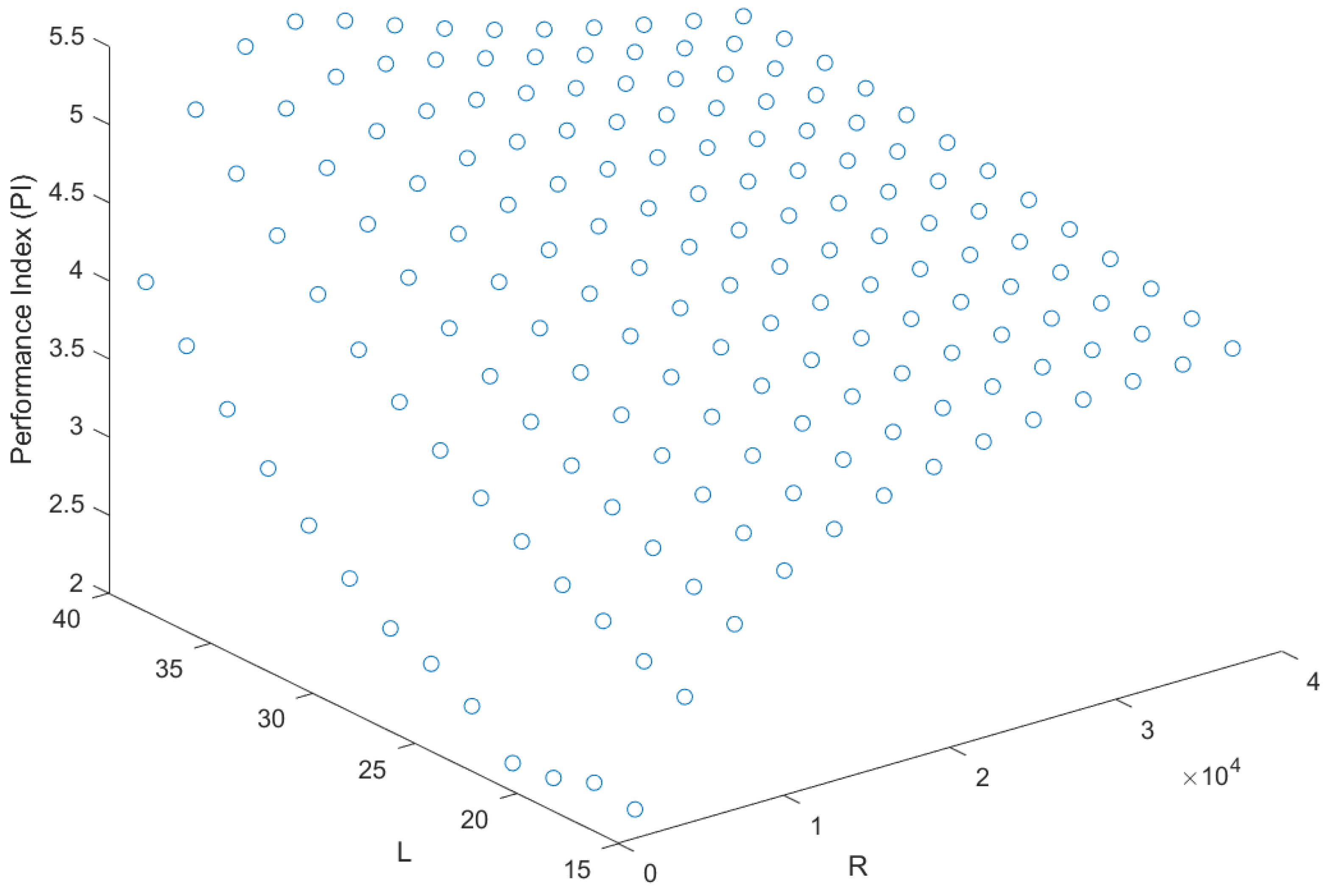
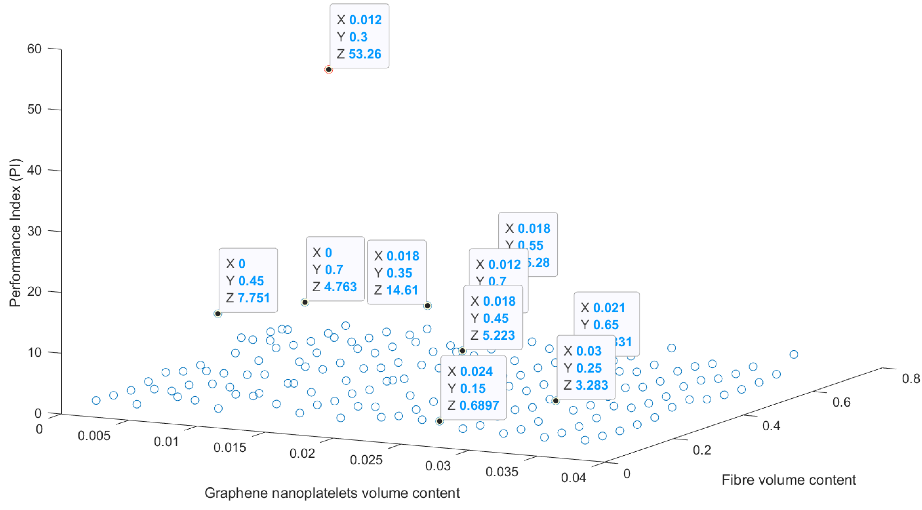
A data-driven machine learning methodology is adopted in this article, aiming to investigate the vibration response of a shunted piezoelectric composite beam. A dataset is first developed using parametric finite element simulations, considering various input and output parameters. Input parameters are the R and L properties of the shunted piezoelectric beam, the graphene nanoplatelets volume content V G P L , the fibre volume content V F , and the fibre angles θ . Output parameters are the vibration reduction achieved by the shunted piezoelectric beam ( P I ), as well as the first and second natural frequencies for the short-circuit and the first and second natural frequencies for the open-circuit conditions.
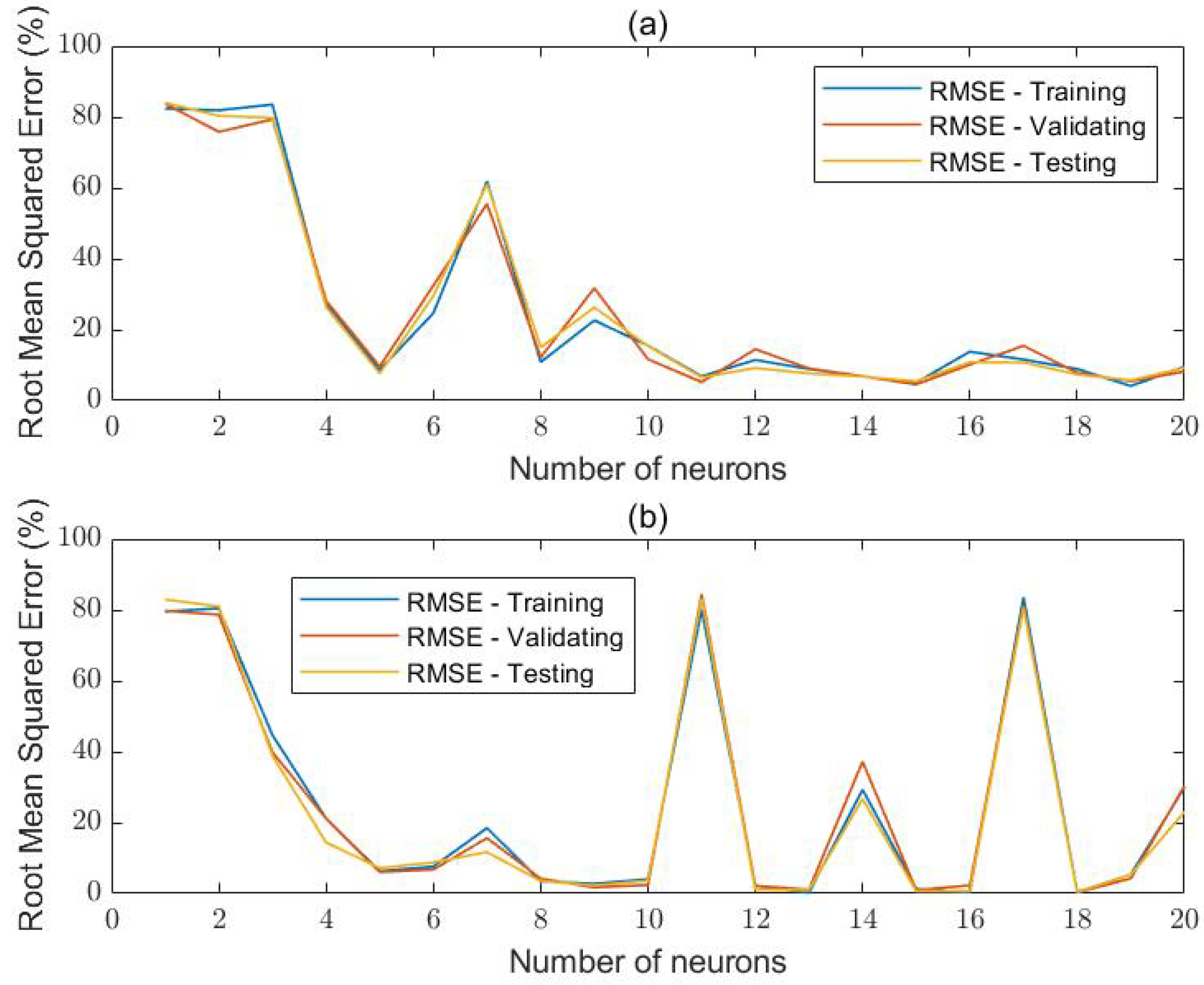
Those input and output parameters are used to train, validate, and test two artificial neural networks in Matlab. After a parametric investigation, an optimal architecture of two hidden layers and 13 neurons per hidden layer is chosen for this study.
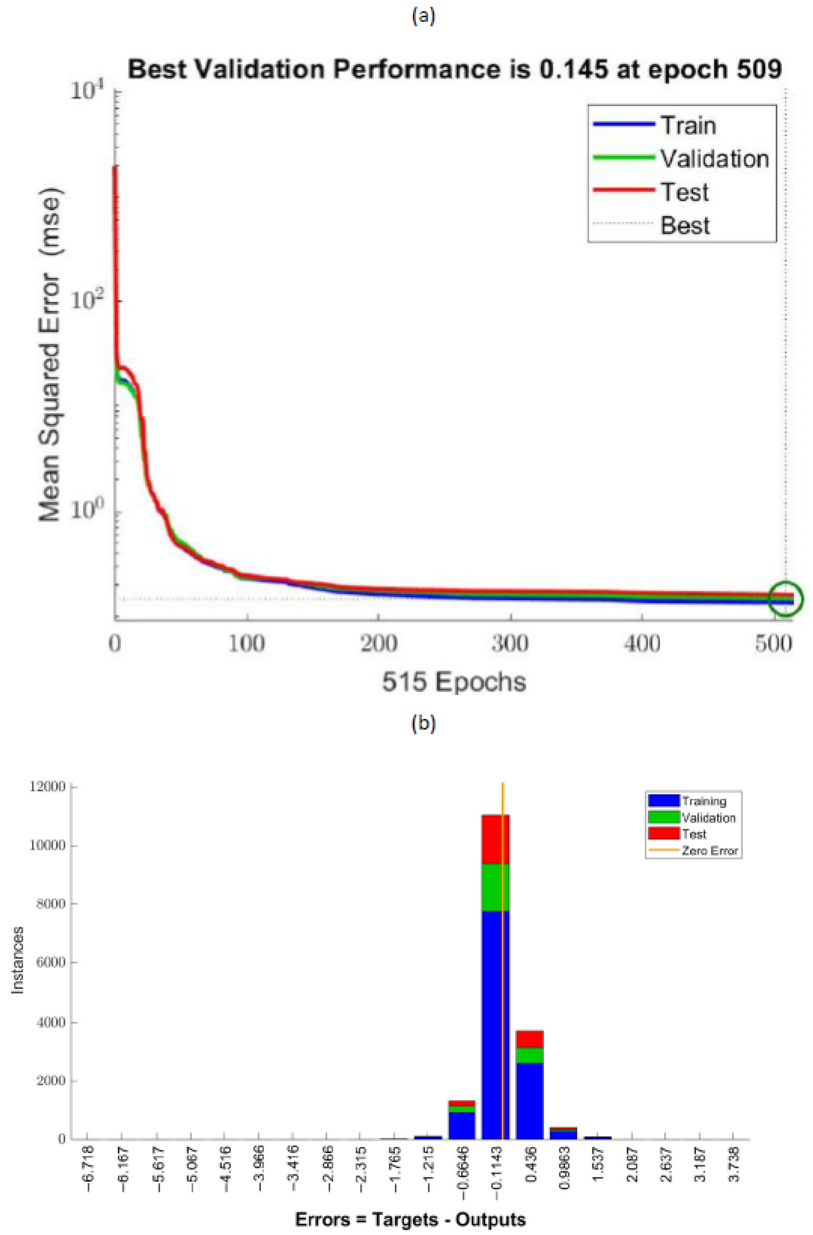
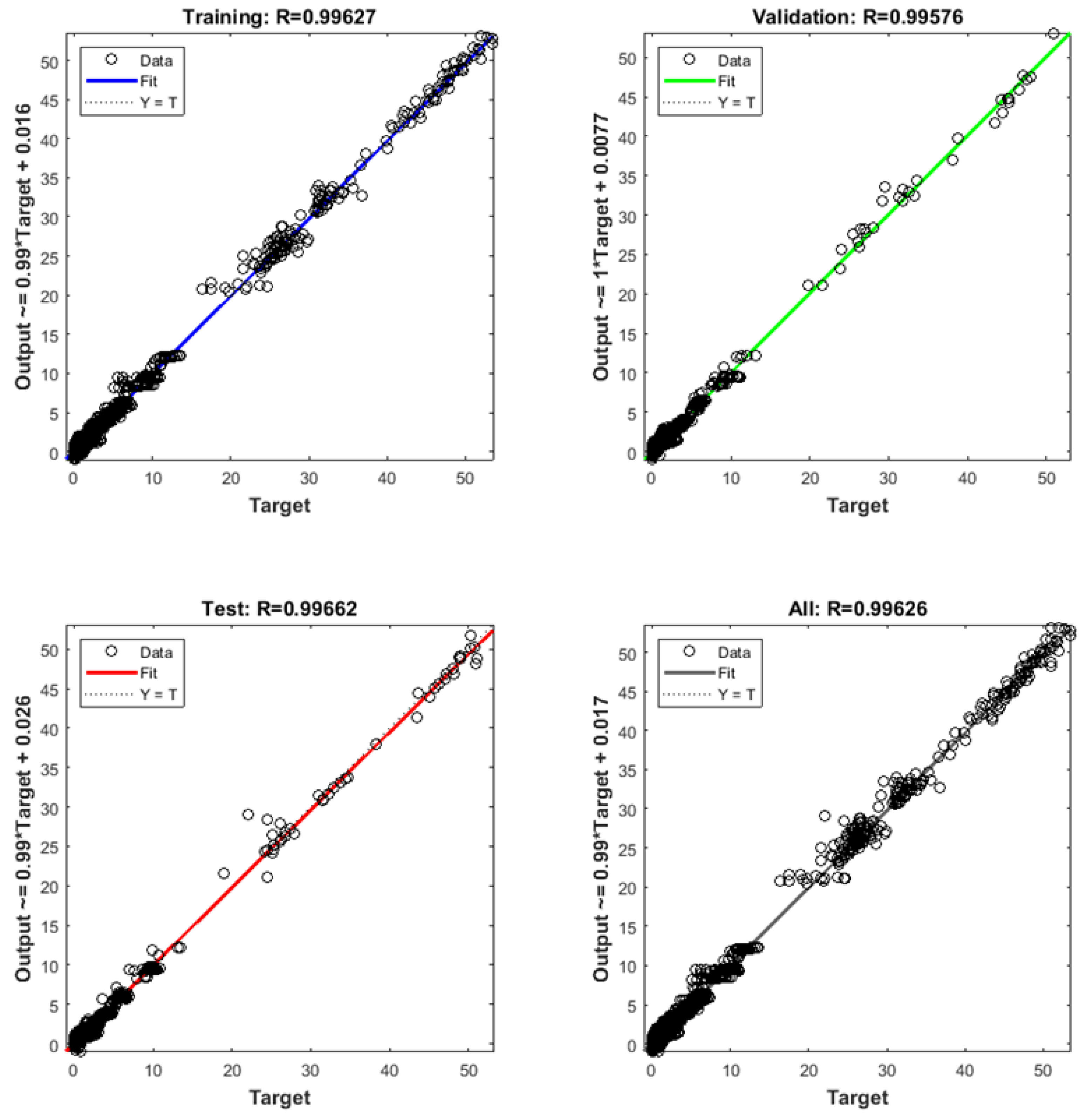
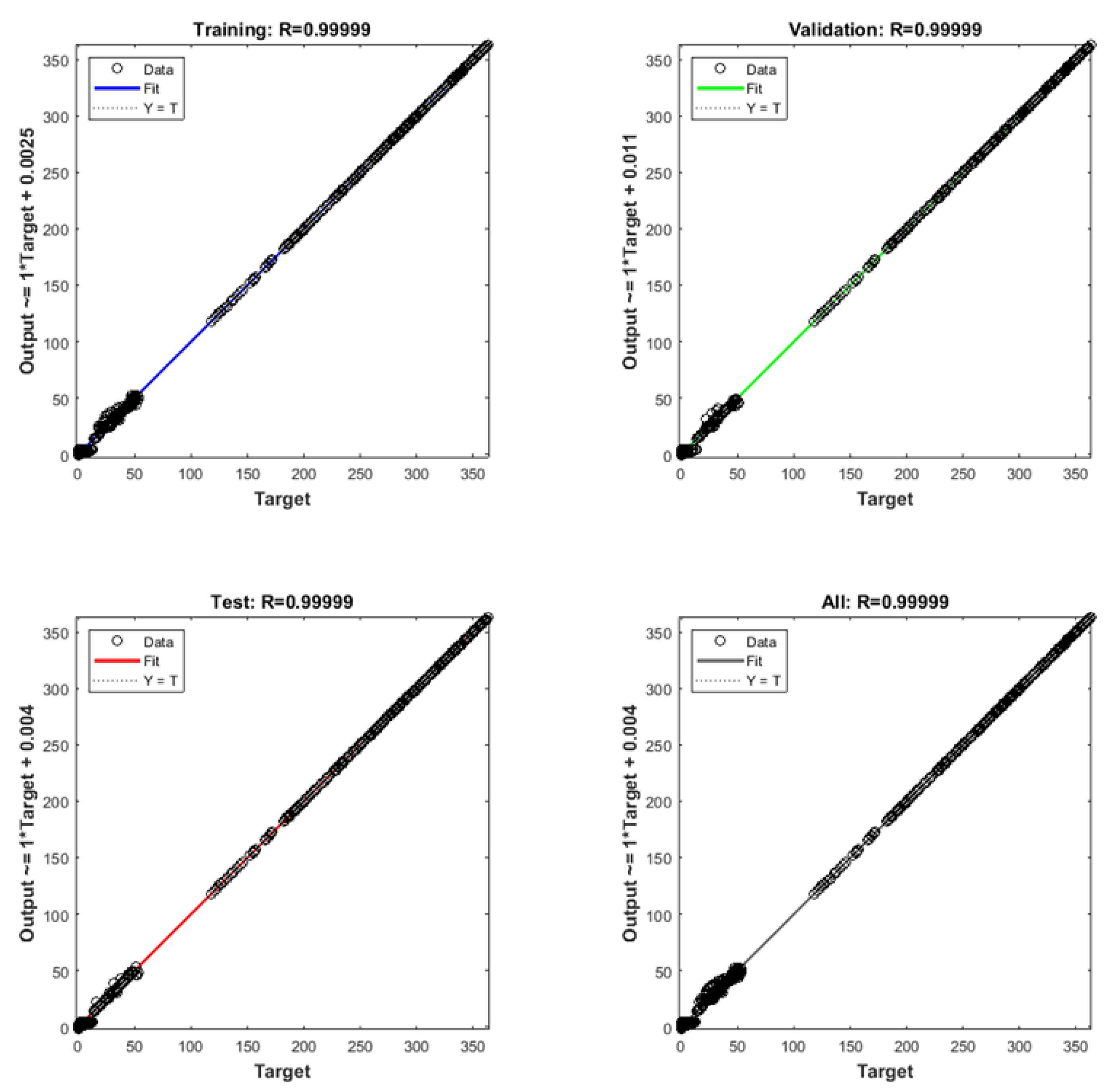
Results of the investigation indicate that the accuracy of the trained ANNs to predict the vibration response of the composite beam is high. In addition, relevant regression diagrams provide high values for the correlation factor (close to 1), indicating a high correlation between the predicted parameters by the trained ANNs and the real dataset values.
The methodology offers the opportunity for a fast and accurate prediction of the mechanical response of composite beams under vibration analysis. It is noted, that though a single finite element simulation of this type has a relatively low computational cost, the effort, time, knowledge, and expertise needed to develop relevant numerical models in a programming code (like Matlab or Python) are pretty demanding. This further increases the impact of the proposed approach in evaluating the mechanical response of those systems.
Future studies can include the investigation of different beam geometries involving potentially varying numbers of input and output parameters, incorporating, for instance, the geometric parameters of the beam, the piezoelectric patch thickness, etc.

Author Contributions

The contributions to this article include: conceptualization, G.D.; methodology, G.D. and G.F.; software, G.D. and G.F.; validation, G.D. and M.-S.D.; formal analysis, M.-S.D.; investigation, G.D. and M.-S.D.; resources, G.D., G.F. and M.-S.D.; data curation, G.D.; writing—original draft preparation, G.D. and G.F.; writing—review and editing, G.D. and G.E.S.; visualization, G.D.; supervision, G.D. and G.E.S.; project administration, G.F. All authors have read and agreed to the published version of the manuscript.

Funding

This research received no external funding.

Data Availability Statement

The developed datasets will be made available upon reasonable request sent to Georgios Drosopoulos ([email protected]).

Conflicts of Interest

The authors declare no conflicts of interest.

Abbreviations

The following abbreviations are used in this manuscript:
CNTCarbon nanotube
GPLGraphene nanoplatelet
MLMachine Learning
GPLFRGraphene/fibre reinforced
DOFDegree of freedom
FEFinite element
ANNArtificial neural networl
RMSERoot Mean Squared Error

Appendix A. Datasets Information

The datasets generated and/or analysed during the current study will be made available to researchers upon request. In particular, the available files are in Matlab format (“.mat” files) providing all input and output parameters of the datasets. The name of each “.mat” file, the corresponding Matlab variable and the related input-output parameter are described below:
  • input_all.mat: ’ann_input’ variable, 16807 dataset lines of all input parameters (R-first column, L-second column, V G P L -third column, V F -fourth column, fibre angle θ -fifth column of the .mat file)
  • output_frequency_1_SC.mat: ’ann_output_frequency_1_SC’, 16807 dataset lines of first frequency for the short-circuit configuration
  • output_frequency_2_SC.mat: ’ann_output_frequency_2_SC’, 16807 dataset lines of second frequency for the short-circuit configuration
  • output_frequency_1_OC.mat: ’ann_output_frequency_1_OC’ variable, 16807 dataset lines of first frequency for the open-circuit configuration
  • output_frequency_2_OC.mat: ’ann_output_frequency_OC’, 16807 dataset lines of second frequency for the open-circuit configuration
  • output_PI.mat: ’ann_output_PI’, 16807 dataset lines of the shunt damping performance P I
  • output_all.mat: ’ann_output’, 16807 dataset lines of all output parameters (first frequency (short-circuit), second frequency (short-circuit), first frequency (open-circuit), second frequency (open-circuit), P I

References

  1. Mahmood, T.; Ullah, A.; Ali, R. Improved nanocomposite materials and their applications. In Nanocomposite Materials for Biomedical and Energy Storage Applications; 2022. [Google Scholar] [CrossRef]
  2. Alhakeem, M.R.H. An Overview of modeling of nano-composite materials and structures. Brill. Res. Artif. Intell. 2022, 2, 145–161. [Google Scholar] [CrossRef]
  3. Aldosari, H. Graphene reinforced polymer matrix nanocomposites: Fabrication method, properties and applications. In Graphene—A Wonder Material for Scientists and Engineers; 2022. [Google Scholar] [CrossRef]
  4. Thai, C.H.; Ferreira, A.; Tran, T.; Phung-Van, P. Free vibration, buckling and bending analyses of multilayer functionally graded graphene nanoplatelets reinforced composite plates using the NURBS formulation. Compos. Struct. 2019, 220, 749–759. [Google Scholar] [CrossRef]
  5. Jeawon, Y.; Drosopoulos, G.; Foutsitzi, G.; Stavroulakis, G.; Adali, S. Optimization and analysis of frequencies of multi-scale graphene/fibre reinforced nanocomposite laminates with non-uniform distributions of reinforcements. Eng. Struct. 2021, 228, 111525. [Google Scholar] [CrossRef]
  6. Mohamad, N.; Yaakub, J.; Ab Maulod, H.; Jeefferie, A.; Yuhazri, M.; Lau, K.; Ahsan, Q.; Shueb, M.; Othman, R. Vibrational damping behaviors of graphene nanoplatelets reinforced NR/EPDM nanocomposites. J. Mech. Eng. Sci. 2017, 11, 3274–3287. [Google Scholar] [CrossRef]
  7. Moheimani, S.R.; Fleming, A.J. Piezoelectric Transducers for Vibration Control and Damping; Springer Science & Business Media: Berlin/Heidelberg, Germany, 2006. [Google Scholar]
  8. Preumont, A. Vibration Control of Active Structures: An Introduction; Springer: Berlin/Heidelberg, Germany, 2018; Volume 246. [Google Scholar]
  9. Aabid, A.; Parveez, B.; Raheman, M.A.; Ibrahim, Y.E.; Anjum, A.; Hrairi, M.; Parveen, N.; Mohammed Zayan, J. A review of piezoelectric material-based structural control and health monitoring techniques for engineering structures: Challenges and opportunities. Actuators 2021, 10, 101. [Google Scholar] [CrossRef]
  10. Thomas, O.; Ducarne, J.; Deü, J.F. Performance of piezoelectric shunts for vibration reduction. Smart Mater. Struct. 2011, 21, 015008. [Google Scholar] [CrossRef]
  11. Deghboudj, S.; Boukhedena, W.; Satha, H. Free Vibration Analysis of Symmetric Laminated Composite Thin Rectangular Plate and Passive Control with Attached Patches. J. Fail. Anal. Prev. 2021, 21, 1240–1251. [Google Scholar] [CrossRef]
  12. Marakakis, K.; Tairidis, G.K.; Foutsitzi, G.A.; Antoniadis, N.A.; Stavroulakis, G.E. New Optimal Design of Multimode Shunt-Damping Circuits for Enhanced Vibration Control. Signals 2022, 3, 830–856. [Google Scholar] [CrossRef]
  13. Selim, B.; Liu, Z.; Liew, K. Active vibration control of functionally graded graphene nanoplatelets reinforced composite plates integrated with piezoelectric layers. Thin-Walled Struct. 2019, 145, 106372. [Google Scholar] [CrossRef]
  14. Dong, Y.; Li, Y.; Li, X.; Yang, J. Active control of dynamic behaviors of graded graphene reinforced cylindrical shells with piezoelectric actuator/sensor layers. Appl. Math. Model. 2020, 82, 252–270. [Google Scholar] [CrossRef]
  15. Nguyen, N.V.; Lee, J. On the static and dynamic responses of smart piezoelectric functionally graded graphene platelet-reinforced microplates. Int. J. Mech. Sci. 2021, 197, 106310. [Google Scholar] [CrossRef]
  16. Abbaspour, F.; Arvin, H.; Shahriari-Kahkeshi, M. Active control of vibrations of piezoelectric rectangular nanocomposite micro plates reinforced with graphene platelet in thermal ambient considering the structural damping. Int. J. Comput. Methods Eng. Sci. Mech. 2022, 23, 243–262. [Google Scholar] [CrossRef]
  17. Jiang, Y.; Zhang, W.; Zhang, Y.; Lu, S. Nonlinear vibrations of four-degrees of freedom for piezoelectric functionally graded graphene-reinforced laminated composite cantilever rectangular plate with PPF control strategy. Thin-Walled Struct. 2023, 188, 110830. [Google Scholar] [CrossRef]
  18. Pashmforoush, F. Mechanical properties prediction of various graphene reinforced nanocomposites using transfer learning-based deep neural network. Proc. Inst. Mech. Eng. Part E J. Process. Mech. Eng. 2023, 237, 1214–1223. [Google Scholar] [CrossRef]
  19. Ebrahimi, F.; Ezzati, H. A machine-learning-based model for buckling analysis of thermally affected covalently functionalized graphene/epoxy nanocomposite beams. Mathematics 2023, 11, 1496. [Google Scholar] [CrossRef]
  20. Anitescu, C.; Atroshchenko, E.; Alajlan, N.; Rabczuk, T. Artificial neural network methods for the solution of second order boundary value problems. Comput. Mater. Contin. 2019, 59, 345–359. [Google Scholar] [CrossRef]
  21. Guo, H.; Zhuang, X.; Rabczuk, T. A deep collocation method for the bending analysis of Kirchhoff plate. arXiv 2021, arXiv:2102.02617. [Google Scholar] [CrossRef]
  22. Zhao, S.; Zhang, Y.; Zhang, Y.; Zhang, W.; Yang, J.; Kitipornchai, S. Buckling of functionally graded hydrogen-functionalized graphene reinforced beams based on machine learning-assisted micromechanics models. Eur. J. -Mech.-A/Solids 2022, 96, 104675. [Google Scholar] [CrossRef]
  23. Shakir, M.; Talha, M.; Dileep, A. Machine learning based probabilistic model for free vibration analysis of functionally graded graphene nanoplatelets reinforced porous plates. In MECH ADV MATER STRUC; 2023; pp. 1–14. [Google Scholar]
  24. Skansi, S. Introduction to Deep Learning: From Logical Calculus to Artificial Intelligence; Springer: Berlin/Heidelberg, Germany, 2018. [Google Scholar]
  25. Hagan, M.T.; Menhaj, M.B. Training feedforward networks with the Marquardt algorithm. IEEE Trans. Neural Netw. 1994, 5, 989–993. [Google Scholar] [CrossRef] [PubMed]
Figure 1. The GPLFR nanocomposite beam with the shunted piezoelectric system.
Signals 05 00017 g001
Figure 2. Layout of an artificial neural network.
Signals 05 00017 g002
Figure 3. Vibration suppression for varying R , L parameters.
Signals 05 00017 g003
Figure 4. Vibration suppression for varying graphene nanoplatelets ( X ) , and fibre volume ( Y ) contents.
Signals 05 00017 g004
Figure 5. Parametric investigation on the influence of the number of neurons per hidden layer for the ANN model (a), one hidden layer (b), and two hidden layers.
Signals 05 00017 g005
Figure 6. Error obtained from the training, validation, and testing of the ANN with two hidden layers, 13 neurons per hidden layer and one output parameter in the form of (a) mean squared error derived for increasing epoch number, (b) error distribution.
Signals 05 00017 g006
Figure 7. Regression plots obtained from the ANN model with 2 hidden layers, 13 neurons per hidden layer and one output parameter.
Signals 05 00017 g007
Figure 8. Error obtained from the training, validation, and testing of the ANN with two hidden layers, 13 neurons per hidden layer and five output parameters in the form of (a) mean squared error derived for increasing epoch number, (b) error distribution.
Signals 05 00017 g008
Figure 9. Regression plots obtained from the ANN model with 2 hidden layers, 13 neurons per hidden layer and five output parameters.
Signals 05 00017 g009
Disclaimer/Publisher’s Note: The statements, opinions and data contained in all publications are solely those of the individual author(s) and contributor(s) and not of MDPI and/or the editor(s). MDPI and/or the editor(s) disclaim responsibility for any injury to people or property resulting from any ideas, methods, instructions or products referred to in the content.

