Article

A Comparison between Ultrasonic Guided Wave Leakage and Half-Cell Potential Methods in Detection of Corrosion in Reinforced Concrete Decks

by
Ahmad Shoaib Amiri
1,*,
Ece Erdogmus
2 and
Dana Richter-Egger
3
1
Durham School of Architectural Engineering and Construction, University of Nebraska-Lincoln, Omaha, NE 68182, USA
2
School of Building Construction, Georgia Institute of Technology, Atlanta, GA 30332, USA
3
Department of Chemistry, University of Nebraska Omaha, Omaha, NE 68182, USA
*
Author to whom correspondence should be addressed.
Signals 2021, 2(3), 413-433; https://doi.org/10.3390/signals2030026
Submission received: 25 September 2020 / Revised: 2 June 2021 / Accepted: 23 June 2021 / Published: 30 June 2021
(This article belongs to the Special Issue Advanced Signal/Data Processing for Structural Health Monitoring)

Abstract

:
This article presents the advantages and limitations of a recently developed Ultrasonic Guided Wave Leakage (UGWL) method in comparison to the well-known Half-Cell Potential (HCP) method in their ability to detect corrosion in reinforced concrete (RC) bridge decks. This research also establishes a correlation between UGWL data and chloride content in concrete RC slabs. Concrete slabs submerged in a 10% NaCl solution were monitored using both methods over a period of six months. The chloride content from the three cores (0.84, 0.55, and 0.18%) extracted from the slab after the 6-month long process all exceeded the chloride threshold values suggested in ACI 318, which is 0.05 to 0.1% by weight of concrete. Further, the UGWL method detected changes due to corrosion approximately 21 days earlier than the HCP method.

1. Introduction

This work has the following two main goals: First, to compare the advantages and the limitations of the recently developed Ultrasonic Guided Wave Leakage (UGWL) approach and the better-known Half-Cell Potential (HCP) method in the detection of corrosion in reinforced concrete (RC) bridge decks. Secondly, to establish a quantitative correlation between UGWL data and chloride content.
In prior work, the UGWL method, a new approach to non-destructive testing (NDT) of reinforced concrete members using ultrasound, demonstrated the ability to detect the onset of corrosion and delaminations between rebar and concrete [1,2,3]. It was demonstrated that the UGWL method can be used effectively on epoxy-coated bars and the method’s field readiness was tested through two field pilot studies. On the other hand, HCP is a well-known and standardized method used to detect corrosion in RC systems and is commonly used on bridge deck inspections. To establish the goals of the project, an experimental program was conducted. The two methods are compared using data from lab specimens submerged in 10% NaCl over a period of six months. In addition, the chloride content in the concrete was determined at the end of the period and correlated to the data from UGWL and HCP methods.

Significance

In this research, two NDT techniques (UGWL and HCP) have been used and compared for the detection of corrosion from the onset and through mild corrosion build-up. The team’s previous work on the UGWL method showcased that it can detect changes in the condition of an RC element sooner than any other method currently available. Early detection of corrosion activity with an established statistical certainty can reduce significant issues with bridge decks and reduce maintenance and repair costs for the departments of transportation (DOTs). This paper builds upon the prior work on the development of the UGWL method. The specific contributions presented here are as follows: (1) providing a comparison to the HCP method in a variety of ways (e.g., time of detection, limitations in application, etc.), and (2) quantifying the level of corrosion in terms of changes in the UGWL amplitudes with respect to measured chloride levels.
It is estimated that more than half of the bridges in the United States are made up of reinforced concrete [4]. Three major causes that lead to the deterioration of RC bridge decks are chloride-induced corrosion, freeze–thaw cycles, and poor construction practices [5]. Corrosion is a major problem with RC bridge decks, especially from chloride products and carbon dioxide [6]. Approximately 15 percent of deterioration in RC bridge decks is caused by corrosion; more than any other degradation mechanism [7]. Corrosion in RC structures leads to significant repair costs, sometimes exceeding the initial cost of construction or even resulting in structural collapse [8]. The annual repair cost caused by corrosion in highway bridges is around USD 8.3 billion, of which approximately USD 2 billion is for bridge decks [9]. Thus, early corrosion detection in RC bridge desks should provide long term cost savings and improve the infrastructure’s function, reliability, and lifespan.
The motivation for comparing the UGWL and HCP methods is also two-fold: First, because UGWL is a newly developed non-destructive evaluation technique for the detection of corrosion in RC bridge decks, it is important to benchmark it with a monitoring method traditionally used by DOTs, such as HCP, to highlight its advantages over the existing approach. Second, detecting corrosion activity at earlier stages than the previously established methods (i.e., HCP) can help better prevent progression of the corrosion into irreversible damage, such as cracking, spalling, and delamination in the bridge deck. Detecting these problems earlier can significantly reduce the costs associated with repairs.

2. Background

2.1. Causes and Mechanism of Corrosion

Corrosion is commonly caused by chloride ingress to the rebar from deicing salts, groundwater, or seawater [10]. At early stages, steel remains in the passivated state, having a high pH (around 12.5), and it is protected by a thin and dense layer of iron oxide that impedes anodic reactions from happening [11]. However, this protective layer can be damaged, and corrosion can be initiated when the chloride ions reach the rebar [12,13]. As the corrosion progresses, it can lead to cracking, delamination, and eventual repair needs. Several procedures are practiced for the prevention of corrosion such as the application of mechanical barriers (i.e., membranes), chemical protection such as corrosion inhibitors, and enhancing the quality of concrete. Though these prevention measures are helpful, corrosion of RC structures is still common and the repairs still costly. Identifying corrosion and related deterioration in its early stages can reduce repair costs [14].

2.2. Chloride Content Analysis

Corrosion is initiated once the chloride content present in the concrete exceeds a certain threshold, called the chloride threshold level (CTL). This threshold value is also referred to as the critical chloride content in the literature. The CTL is often expressed in terms of “chloride content relative to the weight of the cement” [15]. The CTL can also be expressed as the total chloride content relative to the concrete weight or as a ratio of free chloride to hydroxyl threshold or (Cl):(OH) [15,16,17]. Different standards provide guidance on the CTL for concrete structures. For instance, ACI 318 [18] limits the CTL in concrete in the range of 0.08 to 0.1% by weight of concrete. Table 1 indicates the CTLs provided by other standards, expressed in terms of chloride content relative to percentage weight of the cement.

2.3. Non-Destructive Corrosion Monitoring

To monitor corrosion in RC structures, there are various NDT techniques, which may be classified into six categories as indicated by Zaki [22] and they are as follows: (1) visual inspection; (2) electrochemical methods (i.e., open circuit potential method, resistivity method, polarization resistance, galvanostatic pulse method (GPM), electrochemical noise (EN)); (3) elastic wave methods (i.e., ultrasonic pulse velocity, (UPV), acoustic emission, (AE), and impact echo (IE)); (4) electromagnetic methods (i.e., ground penetrating radar (GPR)); (5) optical sensing methods (i.e., fiber Bragg grating (FBG)); and (6) infrared thermography (IRT).
Visual inspection is a commonly used inspection technique that can be used to monitor the corrosion damage on the surface of RC structures. Nevertheless, this method requires highly experienced staff, and it is not effective in detecting unseen corrosion [22]. Thus, other methods, such as electrochemical methods (i.e., HCP) and elastic wave methods (i.e., ultrasonic testing and AE), are more suitable in detecting corrosion at the rebar level below the surface.
Electrochemical methods, such as HCP, are known to be the most suitable technique for corrosion monitoring. HCP is capable of detecting corrosion regardless of the depth of concrete cover, the rebar size and detailing, and, in addition to indicating the corrosion activity at the most external layers of reinforcement, it can indicate the corrosion in greater depth [23]. However, this method has some limitations, which will be discussed later.
Ultrasonic testing (UT) is an evaluation method consisting of a transmitter and receiver circuit, a transducer, and a display device [24]. The UT measurements can be used to locate the cracks and determine the flaw size. This evaluation system is known for its speed of scanning and good resolution capabilities.
AE is another NDT method that has been extensively used for corrosion monitoring in R structures. Ohtsu and Tomola [25] compared AE with HCP for non-destructive testing of corrosion in RC slabs and analyzed the concentration of chloride ions around the rebar. It was demonstrated that AE monitoring can detect the onset of corrosion activity earlier than HCP. With investigation of the ingress of chloride ions, a correlation between AE activity and chloride concentration was observed. Once the chloride contents surpass 0.3 kg/m3, a high AE activity period is observed, which marks the first stage of the deterioration process caused by NaCl attack. Another stage of high AE activity can be observed once the chloride content becomes higher than 1.2 kg/m3, which corresponds to the second stage of the deterioration process. Li et al. [26] used AE to detect corrosion activity in RC structures at an early stage, where a significant increase in cumulative AE hits can be an indication of the onset of corrosion. Thus, AE can be used as a real-time corrosion monitoring technique that can detect corrosion activity at an early stage.
In this research, UGWL and HCP have been used as two NDT methods for continuous monitoring of corrosion in RC structures. These two methods are further explained in the next section.

3. Methodology

3.1. Ultrasonic Guided Wave Leakage (UGWL) Method

UGWL has the ability to identify the onset and progression of flaws in RC structures such as concrete-rebar delamination, corrosion, and cracking. The team’s previous work successfully demonstrated that UGWL is capable of identifying delaminations as small as 0.2 mm (0.008 in) and the onset of rebar corrosion [1,2,3]. A study conducted by Garcia et al. [2] successfully demonstrated that the amplitude of the leaked energy that radiates from the reinforcing bar waveguide is sensitive to corrosion initiation and cracks.
In ultrasonic testing, the ultrasonic waves can propagate as either bulk waves or guided waves [27]. In case of the bulk wave propagation, which is also known as the normal-beam excitation, the ultrasonic waves are leaked into the surrounding material and the insonified area is limited to the contact point between the sensor and the test material [28]. The insonified area in traditional ultrasonic testing is the region that is flooded with carefully controlled sound waves (i.e., ultrasonic waves), whereas in ultrasonic guided wave propagation, the ultrasonic waves propagate through a waveguide, and the ultrasonic waves can travel longer distances compared to bulk wave propagation.
In the UGWL method proposed by the authors, the leaked energy in the guided wave system propagates through the surrounding materials (i.e., concrete) [28], and is detected by a receiver on the surface of the concrete. While a range of ultrasonic frequencies (20–100 kHz) have been used in homogeneous concrete systems, 54 kHz was found to be optimal for this application [1]. Most ultrasonic guided wave studies on RC structures have utilized lower ultrasonic frequencies [1,2,3,27,29,30], mostly because the lower frequencies have a higher sensitivity to bond conditions and are easier to solve [27]. Since the concrete is a heterogeneous material, many agree that it is better to use lower frequencies in ultrasonic testing, typically 20 to 100 kHz [27]. Though higher frequencies are more sensitive to smaller defects and can be used with specimens with smaller thicknesses, they are also prone to higher attenuation [31].
In the UGWL testing method, the following two types of transducers are involved: (1) transmitter; and (2) receiver [28]. A transmitter is used to transmit the ultrasonic waves through the waveguide (such as the steel bar in this case). These ultrasonic waves naturally leak into the surrounding material (i.e., the concrete) and are monitored using the receiver. In the UGWL method, the transmitter is connected to the rebar, either directly to its end or at an angle by a couplant. The couplant facilitates the sensor-to-material connection and makes it easy to transmit the ultrasonic pulses from the transmitter to the waveguide. While collecting the test data, the transmitter can either be held connected to the rebar by hand while taking measurements, or attached using a transducer wedge, for hands-free operation and reduced human error.
The experimental set-up includes two 54 kHz transducers used as transmitter (T), and receiver (R), both having a diameter of 3 cm (1.18 in). The PULSONIC Ultrasonic Pulse Analyzer 58-E4900 from CONTROLS-Group is used as the data acquisition system and to generate the ultrasonic pulses, Figure 1.
The ultrasonic guided wave approach is typically used for inspecting long homogenous materials, such as steel pipes, with the receiver typically placed at the other end of the linear element. However, in this novel approach, instead of depending on the longitudinal waves that propagate and attenuate through the wave guide, the energy that is leaked into the surrounding medium (concrete) is measured by placing an array of receivers on the surface of the concrete. As such, the method is also different than other UT methods traditionally used for concrete structures that utilizes bulk waves that propagate perpendicular to the system.
When the transmitter is on the rebar and receivers are on the surface of concrete; flaws in the steel rebar, steel-concrete interface, and concrete along the path of the leaked waves are observed as changes in the amplitudes of the leaked waves. Another unique aspect of the UGWL method is the use of amplitude readings (frequency domain) instead of the velocity readings (in time domain) that are typical in the standardized applications of ultrasonic testing. While both sets of data can detect flaws in the RC systems, the changes in the amplitude readings were shown to be far more sensitive and easier to interpret. The change of amplitude is calculated by Equation (1) as follows:
C h a n g e   o f   A m p l i t u d e   ( % ) = ( A i A 0 1 ) × 100
where Ai is the amplitude of 54 kHz in the frequency domain of ith increment of corrosion and A0 is the amplitude of 54 kHz in the frequency domain before corrosion.
Further details of the development of this method and previous findings can be found in [1,2,3].
In a study conducted by Garcia et al. [2] at the University of Nebraska-Lincoln, two sets of concrete slabs were prepared to monitor cracks and corrosion activity. The first set of concrete slabs, 45.7 cm × 30.5 cm × 12.7 cm (18 in × 12 in × 5 in), were prepared with a 5% NaCl solution to accelerate corrosion, with a No. 5 rebar at the center level, placed at a depth of 6.3 cm (2.5 in) from the top surface of concrete. The specimens were also submerged in water with the water level just below the reinforcing bar. After monitoring the specimens for a period of 40 days, the measurements of leaked waves using receivers on the surface of the concrete detected corrosion activity. A direct correlation was noted between the increase in UGWL amplitudes and an increase in the length of time the concrete slabs were exposed to corrosive conditions. Garcia [2] concluded that the UGWL measurements are sensitive to early corrosion activity.
One of the limitations of UGWL is attenuation [28]. This limits the coverage area for testing. Attenuation in UT occurs by intrinsic and geometric effects [22], and UGWL is affected by both [28]. Erdogmus [3] successfully demonstrated the ability of UGWL in the detection of multiple flaws that occur at different locations along the rebar with a single set up. A detection range of up to 427 cm (14 ft.) was achieved in this research using a single test setup. To accurately locate the flaws, a grid of receivers located every 15 cm (6 in) along the rebar is recommended by Erdogmus [3].
Finally, to interpret the UGWL measurements, a specific data analysis method is conducted:
  • The raw data is stored in a “4K9” format using the Pulsonic Ultrasonic Pulse Analyzer.
  • The raw data is then converted to CSV files using the Ultrasonic Pulse Analyzer Data Converter. This raw data in the form of velocities in the time domain.
  • The CSV files are converted to Microsoft Excel documents and time domain data is transformed into frequency domain data using Fourier Analysis.
  • The peak amplitude values in the frequency domain are plotted against distance (i.e., the location of the receiver). This allows to determine the attenuation of the UGWL waves along the wave guide and observe any deviations from the expected (theoretical) attenuation curve that can be due to flaws on the rebar or the rebar-concrete interface.

3.2. Half-Cell Potential Method

The Half-Cell Potential (HCP) method is a rapid and cost-effective in situ testing technique used to identify the existence of active corrosion, which was first developed by Stratfull [32]. Generally, a copper/copper sulfate electrode (Cu/CuSO4) or a silver/silver chloride electrode (Ag/AgCl) reference electrode is placed on the concrete surface right above the rebar and it is connected to the exposed portion of the rebar in order to characterize the electro-chemical behavior of corrosion in the rebar. The HCP method can be used to monitor the corrosion of rebar in concrete bridge decks and other structures, as long as the temperature is more than +2 °C and the rebar is not epoxy coated [33]. ASTM C876 [33] provides a guideline to interpret half-cell measurements. The relationship between the potential measurements and the likelihood of corrosion presence are provided in Table 2. Higher magnitudes of negative half-cell readings indicate a higher probability of corrosion.
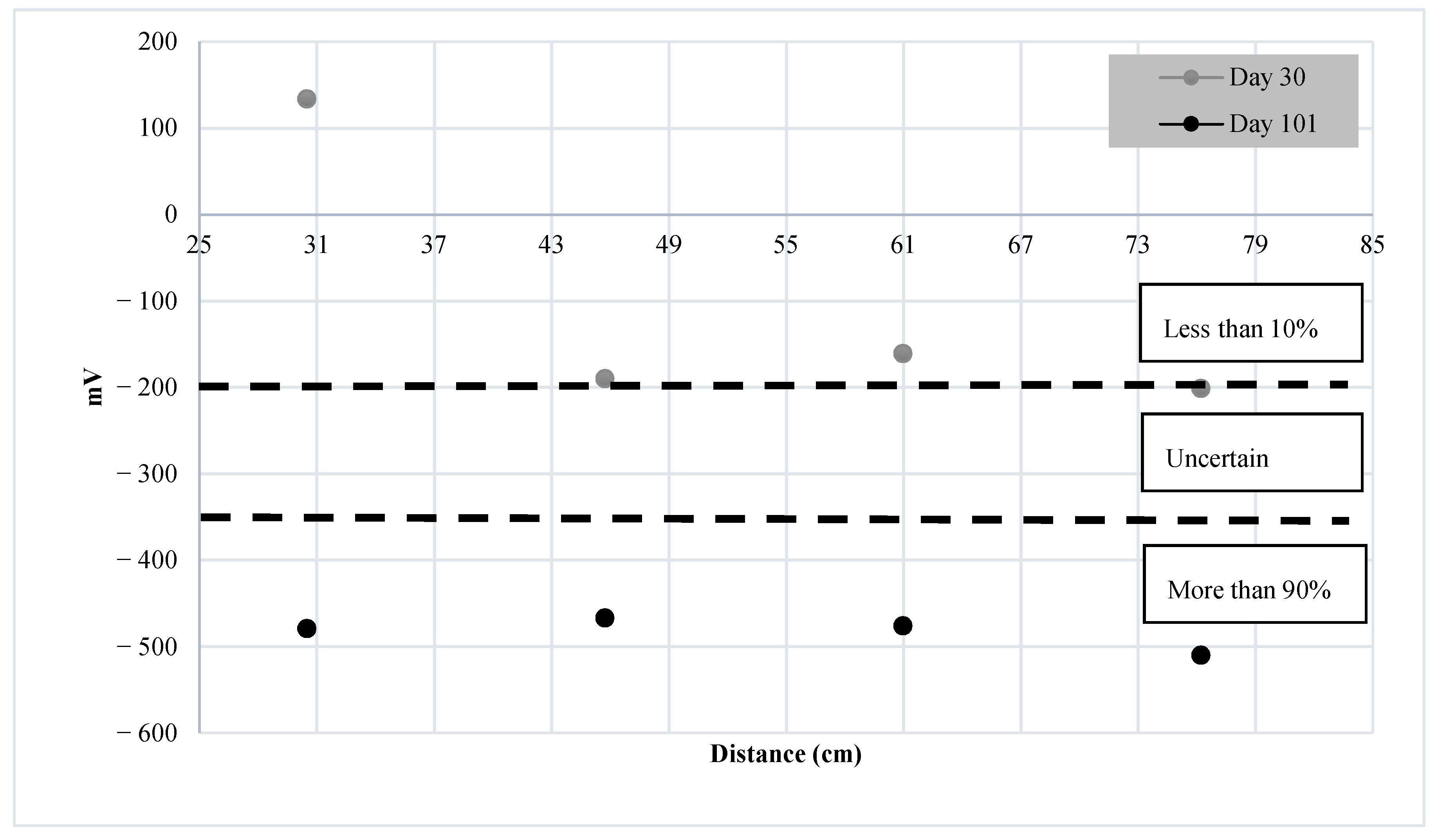
The HCP method has several limitations and is becoming decreasingly useful due to the increased use of epoxy coated rebars [33]. HCP does not provide any detailed information regarding the probability of corrosion activity between −200 and −350 mV, or 10 and 90%. Further, according to Frølund et al. [34], this method is prone to erroneous conclusions in situations where concrete is water-saturated, carbonated, and exposed to very low temperatures.
The HCP technique can be used anytime during the life a structure, and in any environment, as long as the temperature is above +2 °C [33]. Thus, this method can be used non-destructively to monitor corrosion activity in concrete structures.
According to Elsener [23], the HCP method can be used for one of the following main purposes:
  • To locate the corroding reinforcing bars, and thus, to assess the condition of reinforcement during the testing process.
  • To define the position for further destructive analysis such as cores for chloride analysis and inspection windows to visually assess the corrosion condition of the rebars.
  • To evaluate the corrosion condition of the rebar after the repair procedure, and thus, to assess the efficiency and durability of the repair.
  • To design an anode layout of cathodic protection systems.
Elsener [23] also points out that HCP measurements are generally suitable for use on structures that are exposed to the atmosphere. HCP can be used regardless of the depth of the concrete cover, rebar size, and detailing.
According to Pradhan [35], HCP can be used as an indicator of chloride-induced rebar corrosion initiation in RC structures. The top surface of the beam specimens with rebars embedded were subjected to 3% NaCl, followed by exposure to air, in cycles, for a high number of repetitions. It was concluded that HCP is a suitable method to determine the parameter indicating rebar corrosion initiation in chloride-contaminated concrete structures.
Zou [36] investigated the influence of some parameters, such as temperature, humidity, fly-ash content, and the chloride concentration, on the relationship between the HCP and the corrosion level of the rebar in concrete. The results indicated that the HCP decreases with an increase in temperature under the same corrosion level of the reinforcing bar. A decrease in HCP measurements was also observed with an increase in the chloride concentration. With an increase in the fly-ash level, the HCP measurements also increased. When the corrosion level of the rebar increased, the HCP measurements decreased. Yodsudjai [37] also observed a decrease in the HCP measurements when the chloride content increased.
In this project, a Giatech iCOR device is used to collect the HCP measurements and the experimental set-up for this testing procedure is illustrated on the right in Figure 1. “I” denotes the iCOR device on different spots on the concrete surface, and “R” shows the reference electrode that is attached to the rebar. During the procedure, the iCOR device is wirelessly connected to a tablet on which the device can be accessed and controlled. The device shows the value of potentials while the experiment is carried out on the test specimens. The measured data are stored in the tablet, which are then copied onto a computer and plotted for a better representation of data.

3.3. Specimen Details and Data Collection

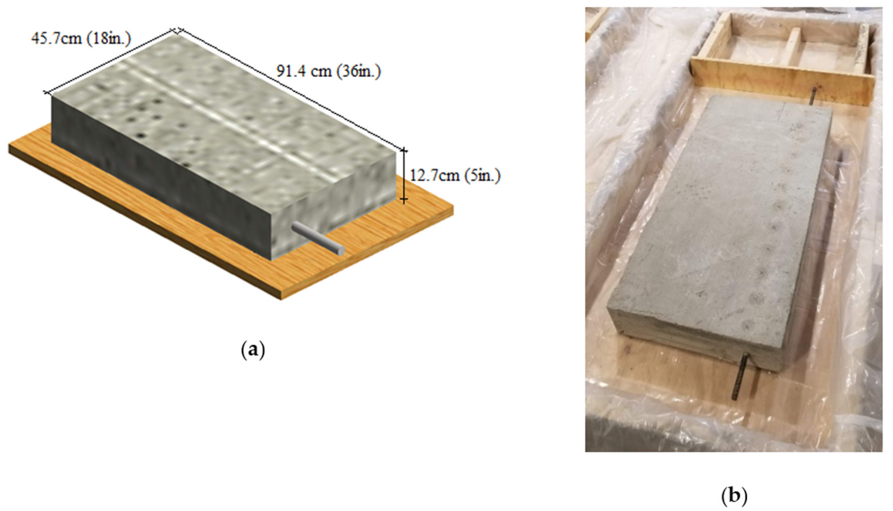
Two RC slabs (designated as Specimen A and B) measuring 91.4 cm × 45.7 cm × 12.7 cm (36 in × 18 in × 5 in) were cast with a No. 4 black rebar (12.7 mm diameter) embedded at the center of the cross-section of the slabs, as shown in Figure 2. The concrete mixture is one typically used by NDOT (Nebraska Department of Transportation) and has a specified strength of 4000 psi.
Researchers have used different concentrations of NaCl in their studies. For instance, Abbas et al. [38] investigated the effect of Cl on segments of a precast concrete tunnel lining, immersed in 3, 3.5, and 10% NaCl solutions. Various tests were conducted on cylindrical cores extracted from reinforced concrete and steel fiber-reinforced concrete segments. It was observed that the difference in the chloride penetration for NaCl concentrations of 3 and 3.5% was insignificant. In contrast, the 10% NaCl concentration specimens showed significant effects from chloride exposure. Based on this prior work, 10% NaCl is also used in this study.
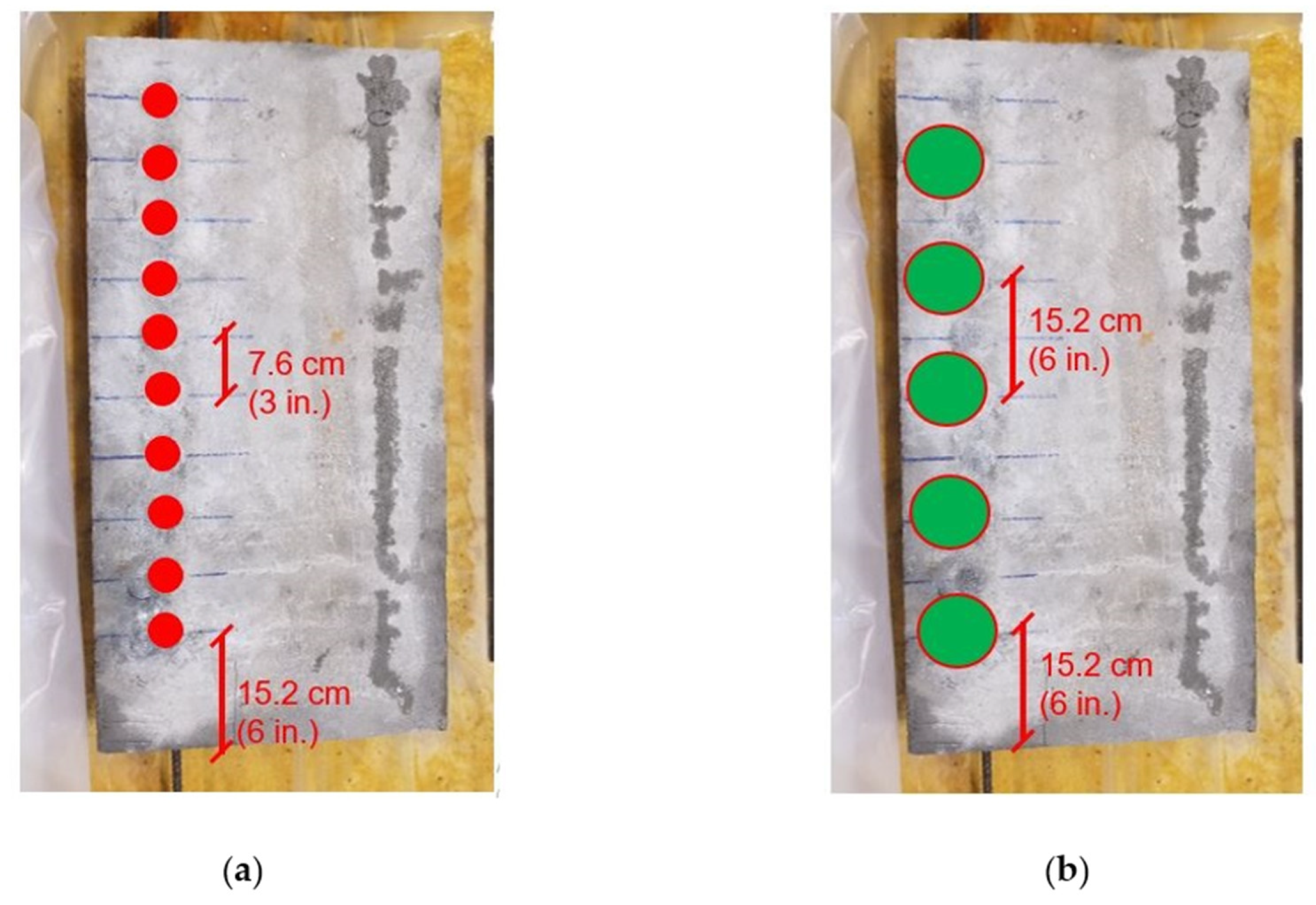
Ten equally spaced spots, 7.6 cm (3 in) apart and starting at 15.2 cm (6 in) from the edge of specimen were tested with UGWL, while five spots 15.2 cm (6 in) apart were tested with HCP (Figure 3). The data were collected once every 3 days for the first 30 days, and every 6 days for the rest of the process. Measurements collected from UGWL method were analyzed in the frequency domain as change in amplitude.

3.4. Measurement of Chloride Content

After the observation of the specimens for six months, the chloride content in Specimen A was measured to establish a quantitative correlation between chloride content and UGWL data. Cores were extracted from three locations: two that demonstrated larger variations in amplitude readings and a third with lower amplitude variation for comparison. Those cores were then pulverized (Figure 4) for chloride analysis using ion chromatography.

4. Results

4.1. Results of Monitoring Corrosion Using UGWL

The change in the recorded UGWL amplitudes during the exposure period are attributed to corrosion activity, given this was the only variable in the experiment. Further, according to previous findings by Garcia et al. [1,2], an increase in the measured amplitude values indicate the onset of corrosion in RC structures. This is because early corrosion improves the bond between concrete and rebar, thus increasing the energy leaked into the surrounding concrete. The first statistically significant increase in amplitudes (53.5%) is observed on day 9 at 30 cm away from the edge (Figure 5). Sample measured amplitudes using UGWL method is presented in Appendix A (Table A1).
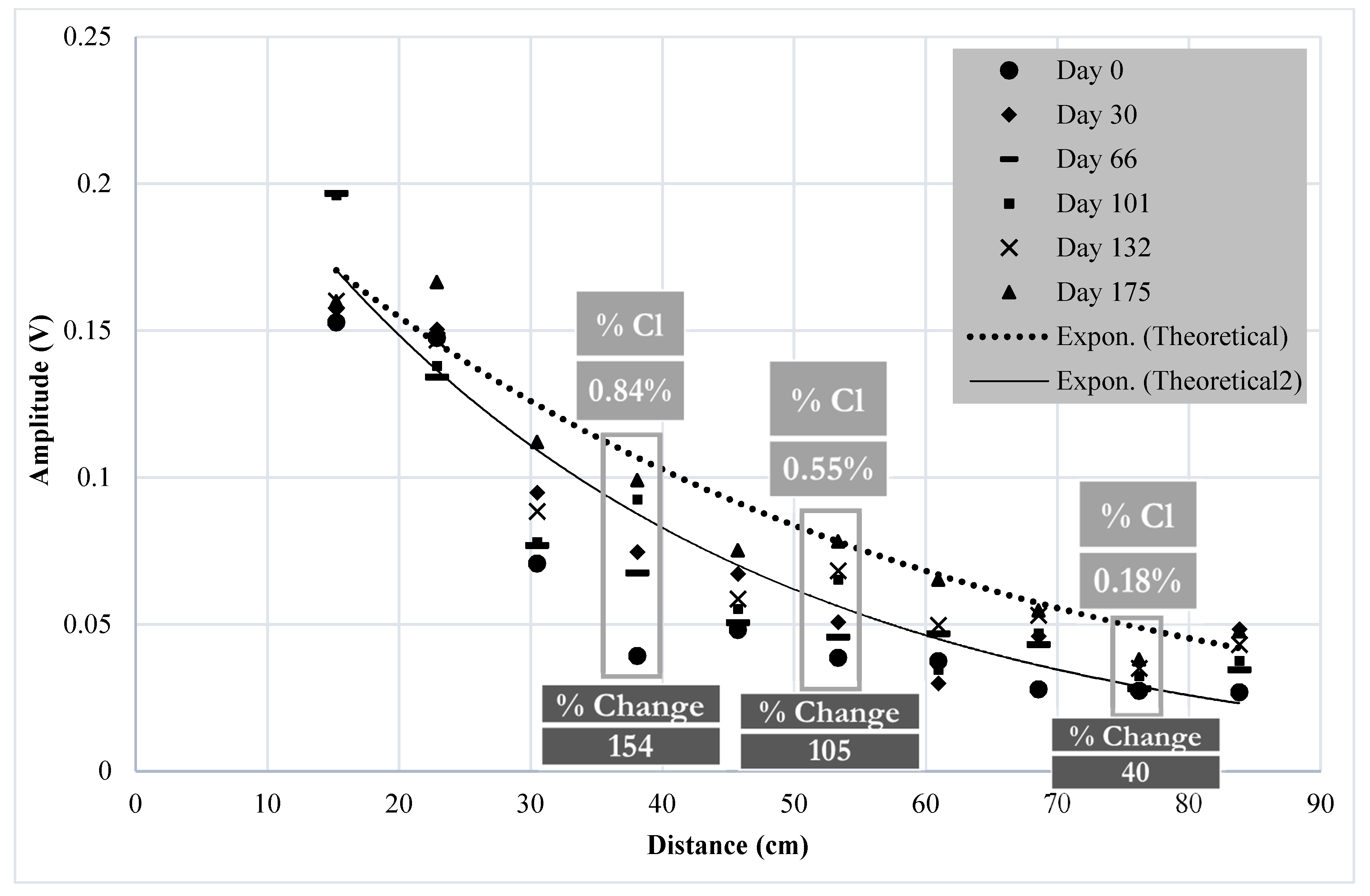
The expected exponential decay of amplitude measurements of the leaked waves along the length of specimen is shown using two theoretical curves in Figure 5. Garcia [27] previously determined these two exponential curves, i.e., the upper and lower bounds, by assuming a high and a low attenuation coefficient. It was observed that the dimensions of the test specimen affected the attenuation. The smaller the dimensions of the test specimen, the more likely that the reflection within the concrete would be detected by sensors, resulting in more variable and higher amplitude readings at the starting end of the guided wave, as well as quicker attenuation. Thus, use of a higher attenuation coefficient is more suitable for smaller specimens. In a study conducted by Garcia [27], the smaller specimen measured 45.7 cm × 45.7 cm × 12.7 cm (18 in × 18 in × 5 in). The attenuation coefficient associated with this smaller size (determined as 0.052) represents the lower bound and it is demonstrated as solid lines in all of the results plots is the paper. The larger specimen used by Garcia [24] measured 168 cm × 45.7 cm × 12.7 cm (66 in × 18 in × 5 in) and showed lower attenuation compared to the smaller specimen. This upper limit exponential curve is represented by a dashed line in the plots. The attenuation coefficient that was obtained from the leaked waves in larger specimens is identical to the attenuation of the guided wave itself, as expected.
In this paper, with the specimens having the dimensions of 91.4 cm × 45.7 cm × 12.7 cm (36 × 18 × 5 in), it is more likely that the attenuation coefficient in this case is similar to that of the smaller specimen (higher attenuation) obtained by Garcia [27]. However, both attenuation curves are used to develop an envelope to better understand this set of specimens’ attenuation behavior.
Figure 6 illustrates select days of measurements from day 0 up to 175 days for the full array of sensors. When the entire period of 175 days is considered, the most significant changes are observed at 38 cm (15 in) and 53 cm (21 in) from the transmitter end. The percent change between “Day 0” and “Day 30” of corrosion for the point at 38 cm (15 in) reaches 95%. Figure 7 further illustrates the change in amplitudes for these two points over the entire period of the experiment. Given that the specimen was continuously submerged in NaCl solution during this period, without any other interventions or change in circumstances, the changes in the UGWL amplitude are attributed to corrosion progression.
As can be seen in Figure 7, there is some fluctuation in the UGWL amplitude measurements. This fluctuation is attributed to testing or user errors (such as the sensor location being slightly different from the previous test, different amounts of couplant used, etc.) as well as the effects of ambient noise. However, when the change in the condition is significant enough (i.e., when a significant amount of corrosion product is built up), there is a significant (or “permanent”) change in the amplitude values. Table 3 quantifies the change in amplitudes for these two points over the entire period of the experiment.
On the 175th day, the percent change in the amplitude for the 38 cm (15 in) point is approximately 154%, while for the 53 cm (21 in) point it is 105%. When the general trend is studied, regardless of the day-to-day fluctuations, a permanent change in amplitude occurs after roughly a 50% change is established. This happens at day 18 for Point 1 (38 cm or 15 in from the edge) and day 83 for Point 2 (53 cm or 21 in from the edge). Consequently, this change in amplitude (50%) is suggested as the indicator of “significant change in the condition of the reinforced concrete slab”. Anything lower than 50% can be considered “uncertain” or “mild deterioration potential”, similar to the HCP uncertainty considerations. To further evaluate this conclusion, the second specimen is discussed below. Later, chloride levels corresponding to the day 175 UGWL readings will be established to further correlate the UGWL amplitude readings to corrosion progression.
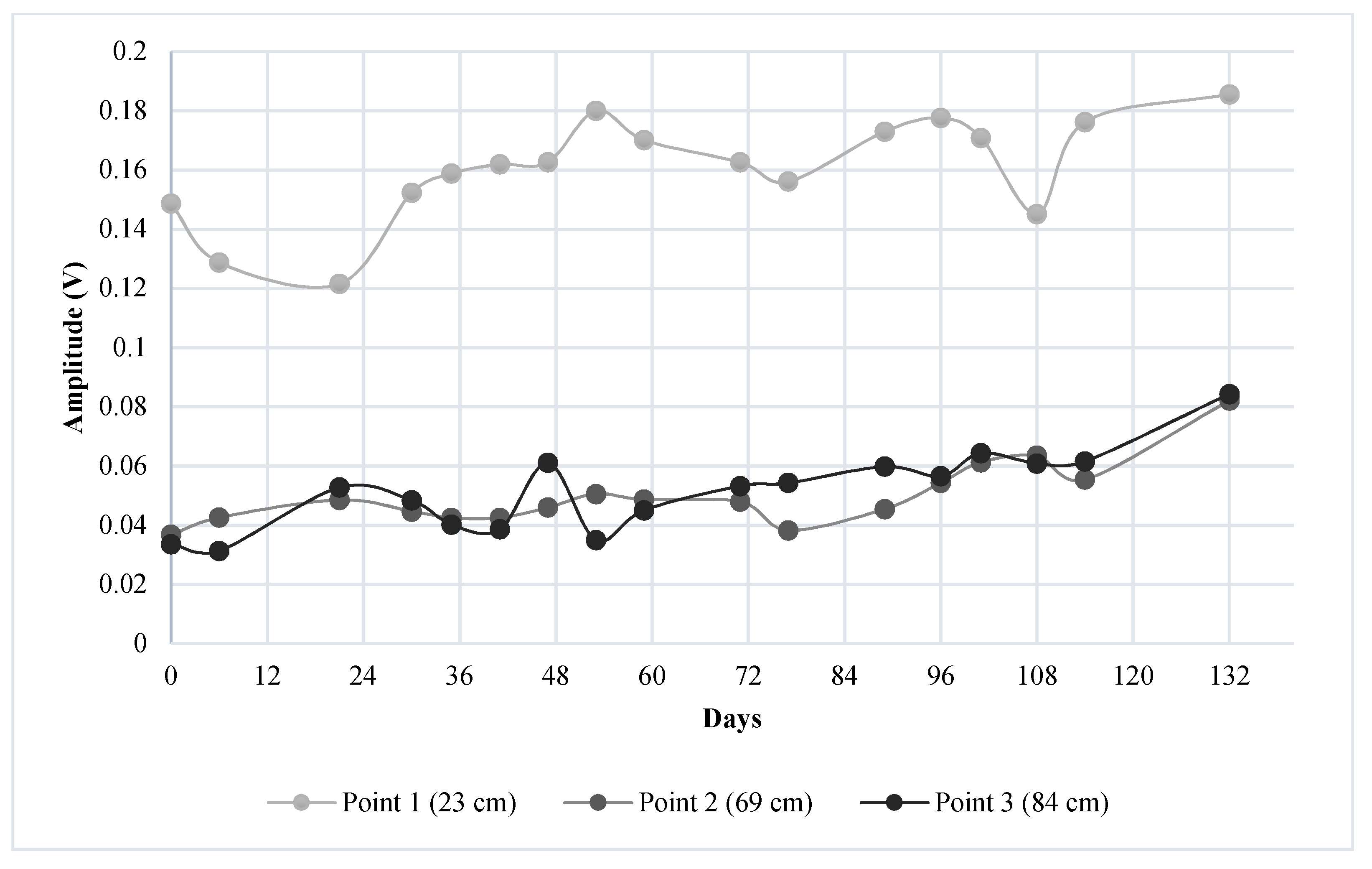
Figure 8 shows the UGWL data for Specimen B for all the measurement points through 132 days of observation, while Figure 9 presents a daily plot showing the change in the amplitudes for three specific points. The generally lower amplitudes in Specimen B compared to Specimen A is due to the fact that the transmitter is attached to the 33-degree cut angle in this case, decreasing the energy propagating through the waveguide. The three points selected for further investigation of this specimen are points at 23, 69, and 84 cm (9, 27, and 33 in, respectively) away from the transmitter end, because these areas showed the most significant changes in UGWL amplitudes (17, 105, and 151 percent, respectively, over the 132 days).
Finally, to establish an intermediary data verification, after monitoring Specimen B for 132 days using the UGWL method, an autopsy was performed, as shown in Figure 10. Some early/mild corrosion build-up can be observed on the rebar that was embedded in this specimen, which correlates to the minor changes in the amplitudes. This experiment confirms that very small changes (such as 17%) in amplitude can be an indication of the onset of the corrosion process.

4.2. Results of Monitoring Corrosion Using HCP

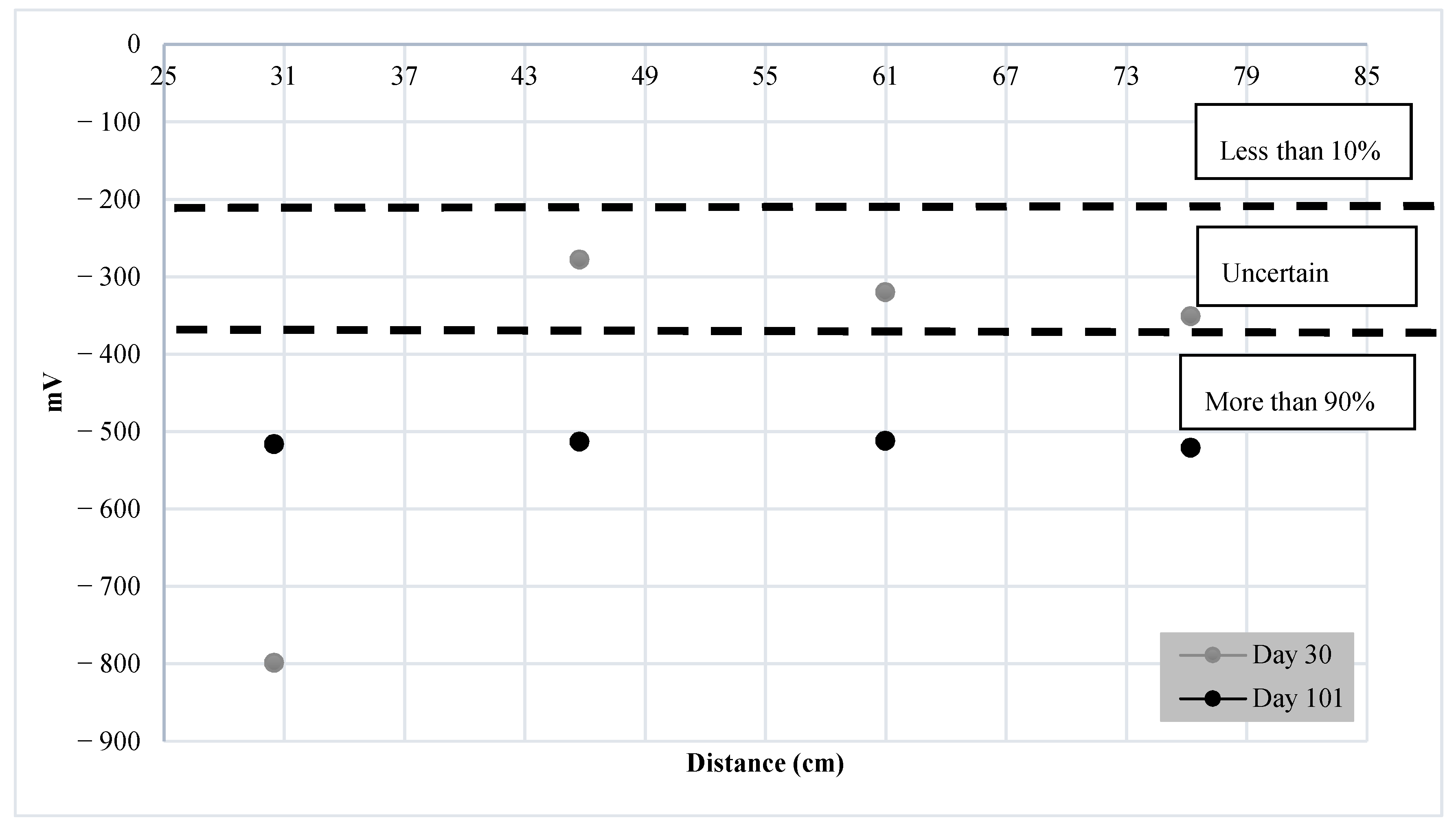
Half-Cell potential measurements were taken using the iCOR device every 6 days on the same day as the ultrasonic testing. Five test locations were marked along the rebar on the surface of the specimen, as shown in Figure 3. The HCP data are presented in terms of volts. ASTM C876 [33] provides a standard, based on which the probability of corrosion presence can be interpreted, as indicated in Table 2. The dotted lines shown in Figure 11 and Figure 12 demonstrate the limits specified by ASTM C876. These limits are also indicated in the text boxes shown on the plots, where each one shows the probability of corrosion. Sample measured amplitudes using HCP method is presented in Appendix A (Table A2).
Figure 11 shows that the HCP measurements for day 30 are mostly in the “uncertain” region according to the interpretations provided by ASTM C876 [33], which means that the probability of corrosion activity can be anywhere between 10 and 90%. Only the 30 cm (12 in) point on this specimen demonstrated a higher probability of corrosion activity per HCP data, which is aligned with the UGWL observations, where there was a significant change (53.5%) at this point as early as day 9. With the HCP readings, none of the points showed a probability higher than 10% for corrosion activity.
The HCP data for Specimen B is presented in Figure 12. All the points measured on day 30 are in the lowest probability (less than 10%) range for corrosion activity per HCP data. While some corrosion activity was detected using the UGWL method earlier than the HCP method on Specimen B, the results of the two methods are in good agreement, in that there is less potential/evidence of corrosion activity for this specimen compared to Specimen A in general. This is also in alignment with the observations from the autopsy shown in Figure 10.

4.3. Comparison of UGWL and HCP

In general, it can be stated that, for Specimen A, the HCP readings started showing an increased probability of corrosion by day 30, whereas the UGWL data demonstrated some increase in the amplitudes as early as day 9. By day 18, a permanent change and significant changes in the amplitude were recorded for some of the points using UGWL, still ahead of the 30-day mark with HCP. Further, Table 4 addresses some of the advantages and limitations of both methods based on previous work.

4.4. Measurement of Chloride Content

Chloride content analysis was conducted on Specimen A after 175 days of conditioning in an NaCl solution. The UGWL data showed the maximum variations for the points 38 cm (15 in) and 53 cm (21 in) away from the edge, as shown in Figure 3; therefore, cores were extracted from these two locations. An additional core was extracted at the 76 cm (30 in) location for comparison purposes to represent points with a lower UGWL amplitude change. The pulverized concrete samples were then sieved using a No. 20 sieve (850 μM) as recommended by ASTM C1152 [21], which provides guidelines on the acid-soluble test for the determination of chloride content in concrete. For each sample, 2 g of homogenized material was mixed with 5 mL of trace-metal-grade nitric acid and 3 drops of Methyl Orange indicator. After the color of the samples became pink, the samples were placed on a hotplate until they began boiling. The samples were then vacuum filtered using Whatman #1 filter paper. The final solutions were diluted to 250 mL using 18 Mohm water. The chloride content was subsequently determined using a Metrohm Eco IC ion chromatograph and a five-point linear calibration curve. Ion separation was achieved using a Metrosep A Supp 4-250/4.0 anion separation column, standard eluent (2.4 mM sodium carbonate and 2.5 mM sodium bicarbonate), and an eluent flow rate of 1.0 mL/minute, all at room temperature. Each sample was analyzed in duplicate along with a method blank.
The results of the chloride content analysis are given in Table 5 and Table 6 for the first and second iterations, respectively, while Table 7 presents the average percentage of chloride concentrations from the two iterations.
As it can be seen Table 5, Table 6 and Table 7, the chloride content of all the samples exceeds the CTL specified by ACI 318, which ranges between 0.05 to 0.1% by weight of concrete. As such, it can be concluded that the chloride content in this specimen has exceeded the chloride threshold values and corrosion activity had definitely started in the rebar by day 175.
Table 8 presents the correlation between the chloride content and the data from both the UGWL and HCP on day 175 (right before CTL check) for points 38 cm (15 in), 53 cm (21 in), and 76 cm (30 in) in Specimen A. There is a strong correlation between all three measurement types.
Figure 13 provides a visual for the correlation between chloride content and the UGWL data, further illustrating the potential of this method in detecting corrosion activity as early as when the chloride levels are right at the threshold of 0.18%.

5. Conclusions

From the work presented in this paper, the following conclusions can be drawn:
  • The experimental results suggest that a 50% change in UGWL data may be the threshold to be considered as a “significant change” in the condition of the rebar or the rebar–concrete interface with respect to corrosion progression in RC bridge decks. While a 50% change provided a permanent change in the data that presents a higher certainty of deterioration, it was verified by visual inspection that UGWL amplitude changes as small as 17% can indicate an onset of corrosion activity.
  • While a larger data population is needed to confirm this finding, less than a 40% change in the UGWL amplitudes correlates to the CTL threshold of 0.1% by weight of concrete established by ACI 318.
  • The findings suggest that when UGWL and HCP are benchmarked, most of the data were in good agreement. The UGWL measurements presented notablechanges in amplitude as early as 9 days, compared to 30 days with HCP. As such, UGWL may have the ability to detect corrosion activity sooner than HCP. In addition to earlier detection, UGWL allows for higher certainty in predictions compared to HCP’s large region of uncertainty, ranging between a 10 and 90% probability of corrosion activity.
  • The experimental results also indicate that noticeable changes in the UGWL readings were recorded as early as 9 days for the lab specimens submerged in 10% NaCl. Over 175 days, the change in the UGWL amplitudes were as high as 154% with respect to the baseline. The 154% increase in the UGWL amplitude change correlated to a 0.84% chloride content, which is higher than the threshold of 0.1% by concrete weight specified by ACI 318. This finding suggests a strong potential for the proposed UGWL method for corrosion monitoring.
  • UGWL has the potential to become a method that can detect multiple flaws with a single setup, because several other advantages of UGWL over HCP are identified in previous work, such as (1) UGWL can be used on epoxy-coated bars, while HCP is limited to use with black bars; and (2) UGWL can detect various flaws (corrosion, delamination, and independent cracks) with one setup, whereas HCP only detects corrosion. As such, UGWL has the potential to become a method that can detect multiple flaws with a single setup.
To improve this new method’s ability in the detection of corrosion in RC structures, future work will involve determining the chloride content at different stages of the NaCl submersion process, as well as at different depths from the concrete’s surface.

Author Contributions

Conceptualization, A.S.A. and E.E.; investigation, A.S.A., E.E., and D.R.-E.; methodology, A.S.A., E.E., and D.R.-E.; project administration, E.E; supervision, E.E.; writing—original draft preparation, A.S.A. and E.E.; writing—review and editing, A.S.A., E.E., and D.R.-E. All authors have read and agreed to the published version of the manuscript.

Funding

This research was funded by the Nebraska Department of Transportation (NDOT) under grant number SPR-P1(19) M086. Any opinions presented in this paper reflect those of the authors and do not necessarily represent those of the funding agency.

Institutional Review Board Statement

Not applicable.

Informed Consent Statement

Not applicable.

Data Availability Statement

Not applicable.

Acknowledgments

This research was funded by the Nebraska Department of Transportation (NDOT). The opinions stated in this paper belong to the authors, and do not necessarily reflect those of the funding organization. The Durham Science Center at the University of Nebraska-Omaha is acknowledged for their support with chloride testing on concrete samples. The authors also present their gratitude to the following undergraduate researchers who assisted in this research: Kelsey Stithem, Mitchael Sieh, Dylan Thompson, Ben Schnatz, and Uziel Ramos.

Conflicts of Interest

The authors declare no conflict of interest.

Appendix A

Samples of UGWL measurements as well as HCP data are given as follows:
Table A1. UGWL measurements for Specimen A.
UGWL: Specimen A
Corrosion Data
Day 30
File nameDistance (in)AmplitudeAvg.Standard Deviation
190.1495289030.1504272850.001433856
290.149136852
390.148896135
490.152310975
590.151683608
690.151007237
7120.0962500920.0947855250.002047222
8120.095550813
9120.096919853
10120.094149955
11120.09507235
12120.094267489
13120.096491907
14120.095200269
15120.09623313
16120.093337921
17150.0747257630.0746677920.000678115
18150.074688041
19150.075483172
20150.075671486
21150.07415704
22150.074486913
23150.074871704
24150.074649849
25150.074428593
26150.073593579
27180.0642331280.067169366
28180.066504016
29180.066432182
30180.06655954
31180.066835837
32180.068642605
33180.067258192
34180.068421715
35180.069637081
36210.0354430790.0350987230.000395379
37210.034969048
38210.035155169
39210.035073283
40210.035794221
41210.035327647
42210.03501156
43210.034839785
44210.035085114
45210.034288329
46240.0327877190.029891370.00239568
47240.032139173
48240.03236147
49240.032947254
50240.028859457
51240.029445851
52240.027741543
53240.028028783
54240.027311966
55240.027290484
56270.048668440.0460214390.001493144
57270.048405063
58270.044544714
59270.045752979
60270.04466398
61270.044244212
62270.045965955
63270.045768383
64270.045952916
65270.046247749
66300.0293076970.0268142230.001186757
67300.028548822
68300.029121009
69300.027857985
70300.027242585
71300.026570321
72300.026159675
73300.025861586
74300.02592397
75300.02577665
76330.0498460790.0483669680.002623562
77330.045668294
78330.045455227
79330.044984574
80330.045906164
81330.048896116
82330.052287372
83330.050199868
84330.050795235
85330.049630746
Table A2. HCP measurements for Specimen A.
HCP: Specimen A
Corrosion Data
Day 30
Distance (in)Potential (mV)Average
12−799−799
18−278−278
24−320−320
30−351−351

References

  1. Garcia, E.; Erdogmus, E.; Schuller, M.; Harvey, D. Novel method for the detection of onset of delamination in reinforced concrete bridge decks. J. Perform. Constr. Facil. 2017, 31, 04017102. [Google Scholar] [CrossRef]
  2. Garcia, E.; Erdogmus, E.; Schuller, M.; Harvey, D. Detecting onset of different types of flaws in reinforced concrete. ACI Mater. J. 2019, 116, 73–82. [Google Scholar] [CrossRef]
  3. Erdogmus, E.; Garcia, E.; Amiri, A.S.; Schuller, M. A novel structural health monitoring method for reinforced concrete bridge decks using ultrasonic guided waves. Infrastructures 2020, 5, 49. [Google Scholar] [CrossRef]
  4. Hartt, W.H.; Powers, R.G.; Leroux, V.; Lysogorski, D.K. Critical Literature Review of High.-Performance Corrosion Reinforcements in Concrete Bridge. Applications; United States Federal Highway Administration, Office of Infrastructure, Center for Marine Materials Florida Atlantic University—Sea Tech Campus: Dania Beach, FL, USA, 2004. [Google Scholar]
  5. Hema, J.; Guthrie, W.S.; Fonseca, F.S. Concrete Bridge. Deck Condition Assessment and Improvement Strategies; Utah Department of Transportation: Salt Lake City, UT, USA, 2004.
  6. Tesfamariam, S.; Bastidas-Arteaga, E.; Lounis, Z. Seismic retrofit screening of existing highway bridges with consideration of chloride-induced deterioration: A bayesian belief network model. Front. Built Environ. 2018, 4. [Google Scholar] [CrossRef]
  7. Basheer, P.A.M.; Chidiact, S.E.; Long, A.E. Predictive models for deterioration of concrete structures. Constr. Build. Mater. 1996, 10, 27–37. [Google Scholar] [CrossRef]
  8. Ji, Y.; Zhao, W.; Zhou, M.; Ma, H.; Zeng, P. Corrosion current distribution of macrocell and microcell of steel bar in concrete exposed to chloride environments. Constr. Build. Mater. 2013, 47, 104–110. [Google Scholar] [CrossRef]
  9. Cui, J. Multiple Sensor Periodic Nondestructive Evaluation on Concrete Bridge. Deck Maintenance. Ph.D. Thesis, University of Vermont, Burlington, VT, USA, 2012. [Google Scholar]
  10. Bentz, E.C. Probabilistic modeling of service life for structures subjected to chlorides. Mater. J. 2003, 100, 391–397. [Google Scholar]
  11. Sharma, A.; Sharma, S.; Sharma, S.; Mukherjee, A. Monitoring invisible corrosion in concrete using a combination of wave propagation techniques. Cem. Concr. Compos. 2018, 90, 89–99. [Google Scholar] [CrossRef]
  12. Valcarce, M.B.; Vázquez, M. Carbon steel passivity examined in alkaline solutions: The effect of chloride and nitrite ions. Electrochim. Acta 2008, 53, 5007–5015. [Google Scholar] [CrossRef]
  13. Melchers, R.E.; Li, C.Q. Phenomenological modeling of reinforcement corrosion in marine environments. ACI Mater. J. 2006, 103, 25. [Google Scholar]
  14. Modares, M.; Waksmanski, N. Overview of structural health monitoring for steel bridges. Pract. Period. Struct. Des. Constr. 2013, 18, 187–191. [Google Scholar] [CrossRef]
  15. Angst, U.; Elsener, B.; Larsen, C.K.; Vennesland, Ø. Critical chloride content in reinforced concrete—A review. Cem. Concr. Res. 2009, 39, 1122–1138. [Google Scholar] [CrossRef]
  16. Ann, K.Y.; Song, H.-W. Chloride threshold level for corrosion of steel in concrete. Corros. Sci. 2007, 49, 4113–4133. [Google Scholar] [CrossRef]
  17. Glass, G.K.; Buenfeld, N.R. Chloride-induced corrosion of steel in concrete. Prog. Struct. Eng. Mater. 2000, 2, 448–458. [Google Scholar] [CrossRef]
  18. ACI Committee, and International Organization for Standardization. Building Code Requirements for Structural Concrete (ACI 318-08) and Commentary; American Concrete Institute: Farmington Hills, MI, USA, 2008; Chapter 4; p. 60. [Google Scholar]
  19. Standard, B. Structural Use of Concrete: Code of Practice for Design and Construction, Part. 1, BS 8110; British Standard Institution: London, UK, 1997. [Google Scholar]
  20. ACI Committee 357. 357R-84: Guide for the Design and Construction of Fixed Offshore Concrete Structures (Reapproved 1997); Technical Documents. Published Online January 1; American Concrete Institute: Farmington Hills, MI, USA, 1984. [Google Scholar]
  21. ASTM C. Standard Test. Method for Acid-Soluble Chloride in Mortar and Concrete; Published Online; ASTM: West Conshohocken, PA, USA, 2012. [Google Scholar]
  22. Zaki, A.; Chai, H.K.; Aggelis, D.G.; Alver, N. Non-destructive evaluation for corrosion monitoring in concrete: A review and capability of acoustic emission technique. Sensors 2015, 15, 19069–19101. [Google Scholar] [CrossRef]
  23. Elsener, B.; Andrade, C.; Gulikers, J.; Polder, R.; Raupach, M. Hall-cell potential measurements—Potential mapping on reinforced concrete structures. Mater. Struct. 2003, 36, 461–471. [Google Scholar] [CrossRef]
  24. Gholizadeh, S. A review of non-destructive testing methods of composite materials. Procedia Struct. Integr. 2016, 1, 50–57. [Google Scholar] [CrossRef] [Green Version]
  25. Ohtsu, M.; Tomola, Y. Corrosion monitoring in reinforced concrete by Acoustic Emission. J. Acoust. Emiss. 2003, 21, 157–169. [Google Scholar]
  26. Li, W.; Xu, C.; Ho, S.C.; Wang, B.; Song, G. Monitoring concrete deterioration due to reinforcement corrosion by integrating acoustic emission and FBG strain measurements. Sensors 2017, 17, 657. [Google Scholar] [CrossRef] [Green Version]
  27. Garcia, E.V.C. Identifying the Onset, Type, and Location of Deterioration in Reinforced Concrete Using Ultrasonic Testing. Ph.D. Dissertation, University of Nebraska-Lincoln, Lincoln, NE, USA, 2016. [Google Scholar]
  28. Amiri, A.S. A Comparison between Ultrasonic Guided Wave Leakage and Half-Cell Potential Methods in Detection of Corrosion in Reinforced Concrete Structures. Master’s Thesis, University of Nebraska, Lincoln, NE, USA, 2020. [Google Scholar]
  29. Ervin, B.L. Monitoring Corrosion of Rebar Embedded in Mortar Using Guided Ultrasonic Waves (Doctor of Philosophy). Ph.D. Thesis, University of Illinois at Urbana-Champaign, Champaign, IL, USA, 2007. [Google Scholar]
  30. Mustapha, S.; Lu, Y.; Li, J.; Ye, L. Damage detection in rebar-reinforced concrete beams based on time reversal of guided waves. Struct. Health Monit. 2014, 13, 347–358. [Google Scholar] [CrossRef]
  31. Manning, D.G. Detecting Defects and Deterioration in Highway Structures; NCHRP Synthesis of Highway Practice; Transportation Research Board: Washington, DC, USA, 1985; Volume 118. [Google Scholar]
  32. Stratfull, R.F. The corrosion of steel in a reinforced concrete bridge. Corrosion 1957, 13, 43–48. [Google Scholar] [CrossRef]
  33. ASTM C. 876-99 Standard, Test. Method for Half-Cell Potentials of Uncoated Reinforcing Steel in Concrete; American Society for Testing and Materials: West Conshohocken, PA, USA, 1999. [Google Scholar]
  34. Frølund, T.; Klinghoffer, O.; Sørensen, H.E.; Denmark, D.D. Pro’s and con’s of half-cell potentials and corrosion rate measurements. In Proceedings of the International Conference on Structural Faults, London, UK, 1–3 July 2003. [Google Scholar]
  35. Pradhan, B.; Bhattacharjee, B. Half-cell potential as an indicator of chloride-induced rebar corrosion initiation in RC. J. Mater. Civ. Eng. 2009, 21, 543–552. [Google Scholar] [CrossRef]
  36. Zou, Z.H.; Wu, J.; Wang, Z.; Wang, Z. Relationship between half-cell potential and corrosion level of rebar in concrete. Corros. Eng. Sci. Technol. 2016, 51, 588–595. [Google Scholar] [CrossRef]
  37. Yodsudjai, W.; Pattarakittam, T. Factors influencing half-cell potential measurement and its relationship with corrosion level. Measurement 2017, 104, 159–168. [Google Scholar] [CrossRef]
  38. Abbas, S.; Soliman, A.M.; Nehdi, M.L. Chloride ion penetration in reinforced concrete and steel fiber-reinforced concrete precast tunnel lining segments. Mater. J. 2014, 111, 613–622. [Google Scholar]
  39. Akhtar, S. Review of nondestructive testing methods for condition monitoring of concrete structures. J. Constr. Eng. 2013. [Google Scholar] [CrossRef] [Green Version]
Figure 1. Experimental set-up: (a) UGWL; (b) HCP.
Signals 02 00026 g001
Figure 2. Test specimens: (a) illustration with dimension; (b) actual specimen before submersion.
Signals 02 00026 g002
Figure 3. Test locations on the specimens: (a) UGWL; (b) HCP.
Signals 02 00026 g003
Figure 4. (a) Extracted core from the concrete specimen; (b) Concrete sample in pulverized form.
Signals 02 00026 g004
Figure 5. Specimen A UGWL data: days 0, 3, 6 and 9.
Signals 02 00026 g005
Figure 6. Comparison of select data through 175 days, Specimen A.
Signals 02 00026 g006
Figure 7. Specimen A: UGWL amplitude change for two sensor points over 175 days.
Signals 02 00026 g007
Figure 8. Specimen B—UGWL readings for select days between day 0 and day 132.
Signals 02 00026 g008
Figure 9. Specimen B—Progression of the UGWL readings from three points over time.
Signals 02 00026 g009
Figure 10. Specimen B- Day 132 condition verification: Very mild corrosion build-up on the rebar.
Signals 02 00026 g010
Figure 11. HCP measurements for Specimen A.
Signals 02 00026 g011
Figure 12. HCP measurements for Specimen B.
Signals 02 00026 g012
Figure 13. Correlation between UGWL data and chloride content.
Signals 02 00026 g013
Table 1. Chloride threshold values specified by different standards.
StandardReferenceChloride Threshold Level (CTL) (%, Cement)
Reinforced ConcretePre-Stressed Concrete
British Standard[19]0.40.1
ACI 357 (Water-soluble Cl-)[20]0.10.06
ASTM 1152
(Acid-soluble Cl-)
[21]0.20.08
Table 2. ASTM C876 for interpretation of half-cell measurements [33].
Half-Cell Potential Measurements (Mv)Probability of Rebar Corrosion Activity
>−200Less than 10%
−200 to −350Uncertain
<−350More than 90%
Table 3. Change of amplitude for various points for Specimen A.
UGWL Data PointsDay 0Day 9Day 30Day 101Day 175
Amp.
(v)
Amp.
(v)
% change vs. Day 0Amp.
(v)
% change vs. Day 0Amp.
(v)
% change vs. Day 0Amp.
(v)
% Change vs. Day 0
38 cm (15 in)0.0390.061560.074900.0921360.099154
53 cm (21 in)0.0380.055450.051340.065710.078105
Table 4. Comparison between UGWL and HCP Methods.
ParametersUGWLHCP
Application for other purposesCan be used to detect cracks and delamination in addition to corrosion [2]; n/a
Influence of temperatureNo informationInfluenced by temperature and humidity [37,39]
Need for coupling materialIt needs coupling gel between the sensors and the test materials (i.e., concrete)Not needed
Applicability on structures involving epoxy-coated barIt was successfully used for structures involving an epoxy-coated rebar [1]Not suitable for structures that involves an epoxy-coated rebar [33]
Attachment to the rebarRequired Required
Table 5. Percentage of chloride content per weight of concrete (1st iteration).
SampleMass (g)Volume (L)Solution (ppm)%Cl per Concrete Weight
Method blank00.25000.13--
38 cm (15 in)2.10080.250070.60.84%
53 cm (21 in)2.10370.250047.50.56%
76 cm (30 in)1.98800.250015.20.19%
Table 6. Percentage of chloride content per weight of concrete (2nd iteration).
SampleMass (g)Volume (L)Solution (ppm)%Cl per Concrete Weight
Method blank00.2500Not Detected--
38 cm (15 in)2.04250.250068.70.84%
53 cm (21 in)1.96920.250042.70.54%
76 cm (30 in)2.01000.250014.20.18%
Table 7. Percentage of chlorite content per weight of concrete.
SampleAverage %Cl per Concrete Weight
38 cm (15 in)0.84%
53 cm (21 in)0.55%
76 cm (30 in)0.185%
Table 8. Correlation between CTL and UGWL data.
Measurement LocationUGWL DataHCP Data
Day 0 (Amplitude)Day 175 (Amplitude)Percentage Change in UGWL Reading (%)Day 175
Reading
(mV)
Day 175 Probability of Corrosion ActivityAverage %Cl per Concrete Weight
38 cm (15 in)0.0390.099154%−624>90%0.84%
53 cm (21 in)0.0380.078105%−595>90%0.55%
76 cm (30 in)0.0270.03840%−574>90%0.185%
Publisher’s Note: MDPI stays neutral with regard to jurisdictional claims in published maps and institutional affiliations.