Article

Development and Testing of an AI-Based Specific Sound Detection System Integrated on a Fixed-Wing VTOL UAV

by
Gabriel-Petre Badea
1,2,
Mădălin Dombrovschi
1,2,*,
Tiberius-Florian Frigioescu
1,2,
Maria Căldărar
1,2 and
Daniel-Eugeniu Crunteanu
2
1
National Research and Development Institute for Gas Turbines—COMOTI, 220D Iuliu Maniu, 061126 Bucharest, Romania
2
Faculty of Aerospace Engineering, National University of Science and Technology Politehnica Bucharest, 1-7 Polizu Street, 1, 011061 Bucharest, Romania
*
Author to whom correspondence should be addressed.
Acoustics 2025, 7(3), 48; https://doi.org/10.3390/acoustics7030048
Submission received: 26 May 2025 / Revised: 4 July 2025 / Accepted: 27 July 2025 / Published: 30 July 2025

Abstract

This study presents the development and validation of an AI-based system for detecting chainsaw sounds, integrated into a fixed-wing VTOL UAV. The system employs a convolutional neural network trained on log-mel spectrograms derived from four sound classes: chainsaw, music, electric drill, and human voices. Initial validation was performed through ground testing. Acoustic data acquisition is optimized during cruise flight, when wing-mounted motors are shut down and the rear motor operates at 40–60% capacity, significantly reducing noise interference. To address residual motor noise, a preprocessing module was developed using reference recordings obtained in an anechoic chamber. Two configurations were tested to capture the motor’s acoustic profile by changing the UAV’s orientation relative to the fixed microphone. The embedded system processes incoming audio in real time, enabling low-latency classification without data transmission. Field experiments confirmed the model’s high precision and robustness under varying flight and environmental conditions. Results validate the feasibility of real-time, onboard acoustic event detection using spectrogram-based deep learning on UAV platforms, and support its applicability for scalable aerial monitoring tasks.

1. Introduction

The rapid proliferation of Unmanned Aerial Vehicles (UAVs), particularly fixed-wing Vertical Takeoff and Landing (VTOL) variants, has revolutionized multiple sectors, including surveillance, logistics, environmental monitoring, and military applications [1]. However, the widespread use of UAVs has also introduced significant security, privacy, and safety challenges, necessitating the development of robust detection and classification systems [2]. Among the numerous detection methodologies, acoustic-based systems have gained prominence due to their passive nature, cost-effectiveness, and adaptability in environments where visual or radio frequency (RF) methods may fail [3].
The current research landscape in AI-based sound detection for UAVs is marked by rapid advancements in machine learning (ML) and deep learning (DL) techniques. Convolutional Neural Networks (CNNs) have proven highly effective in processing spectrogram images of audio signals, facilitating accurate UAV detection [4]. Recurrent Neural Networks (RNNs), especially Long Short-Term Memory (LSTM) networks, excel in temporal sequence analysis, enabling reliable detection in low signal-to-noise ratio (SNR) conditions [5]. Hybrid models, such as Convolutional Recurrent Neural Networks (CRNNs), combine the strengths of CNNs and RNNs, offering enhanced detection accuracy [6].
Traditional ML approaches also remain relevant. Support Vector Machines (SVMs) have demonstrated effectiveness when paired with Mel-Frequency Cepstral Coefficients (MFCCs) for feature extraction, achieving high precision in drone detection tasks [7]. Ensemble methods, including Random Forests and Bagged Trees, have shown strong performance in multi-class classification scenarios [8]. Multi-modal sensor fusion, integrating acoustic data with RF and visual inputs, has further improved detection robustness, especially in noisy or obstructed environments [9,10]. Sensor integration is critical for capturing high-quality acoustic data. Microphone arrays, particularly those employing Micro-Electro-Mechanical Systems (MEMS), provide compact and efficient solutions for UAV detection, achieving significant detection ranges [11]. Techniques like Direction of Arrival (DOA) estimation and Beamforming enhance sound localization, improving tracking accuracy [12]. Multi-modal sensor configurations that combine acoustic, RF, and visual data have demonstrated superior performance compared to single-modality systems [13].
Data processing techniques play a crucial role in optimizing detection performance. MFCCs are the most widely used feature extraction method due to their ability to represent perceptual characteristics of audio [14]. Wavelet Scattering Transform (WST) has proven effective in providing multi-resolution time-frequency representations, enhancing robustness against noise [15]. Data augmentation methods, such as noise addition, pitch shifting, and time delays, further improve model generalizability [16]. Rigorous testing and validation are essential to ensure system reliability. Key metrics, including accuracy, precision, recall, and F1-score, are used to assess model performance [17]. Detection range and robustness against environmental factors, such as noise and signal attenuation, are also critical performance indicators [18]. Real-time performance is another essential aspect, with systems achieving low-latency predictions through optimized algorithms [19]. Despite notable progress, several challenges persist in the field of acoustic UAV detection. These include maintaining high detection accuracy in noisy environments, optimizing detection range without excessive computational costs, and ensuring real-time processing capabilities. Future research must address these issues, focusing on advanced feature extraction methods, enhanced sensor integration, and optimized ML models [20,21].
This paper provides a comprehensive review of AI-based acoustic detection systems for fixed-wing VTOL UAVs. By examining recent advancements in algorithms, sensor integration, data processing techniques, and testing methodologies, we identify current limitations and propose future research directions. Our objective is to advance the development of reliable, efficient UAV detection systems capable of operating effectively in diverse environments.

2. Materials and Methods

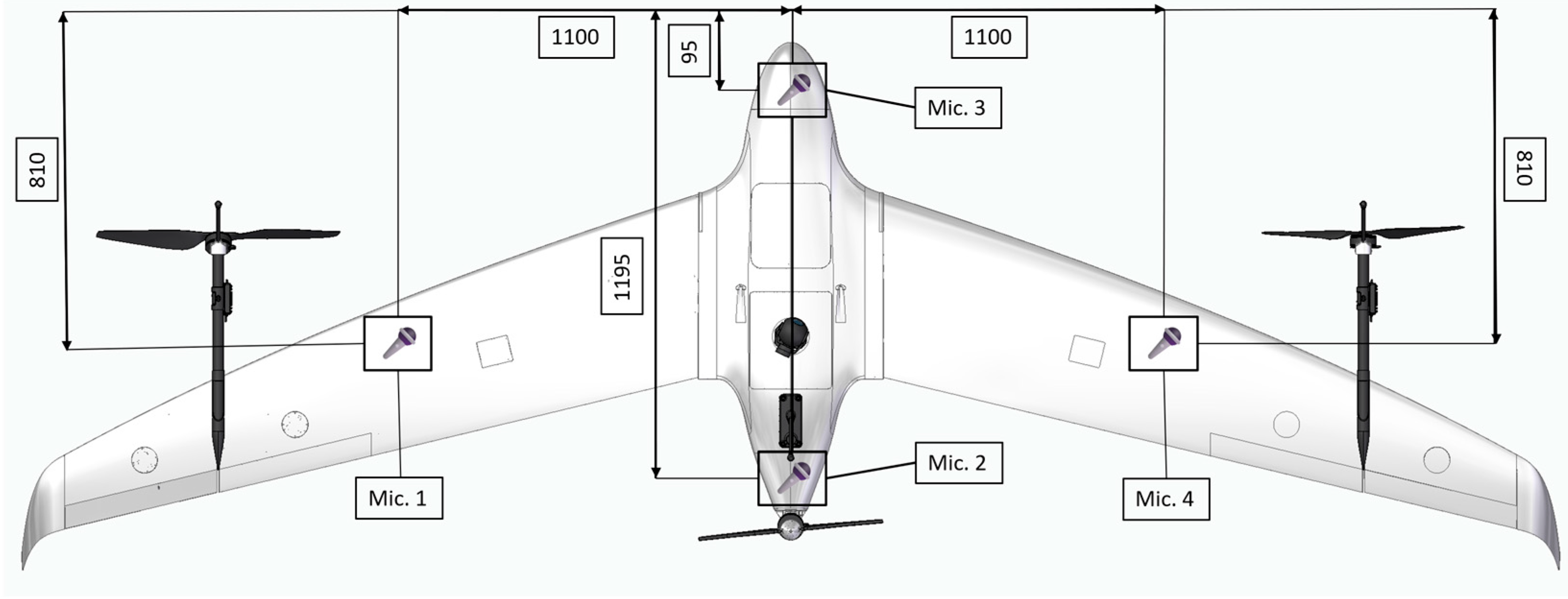
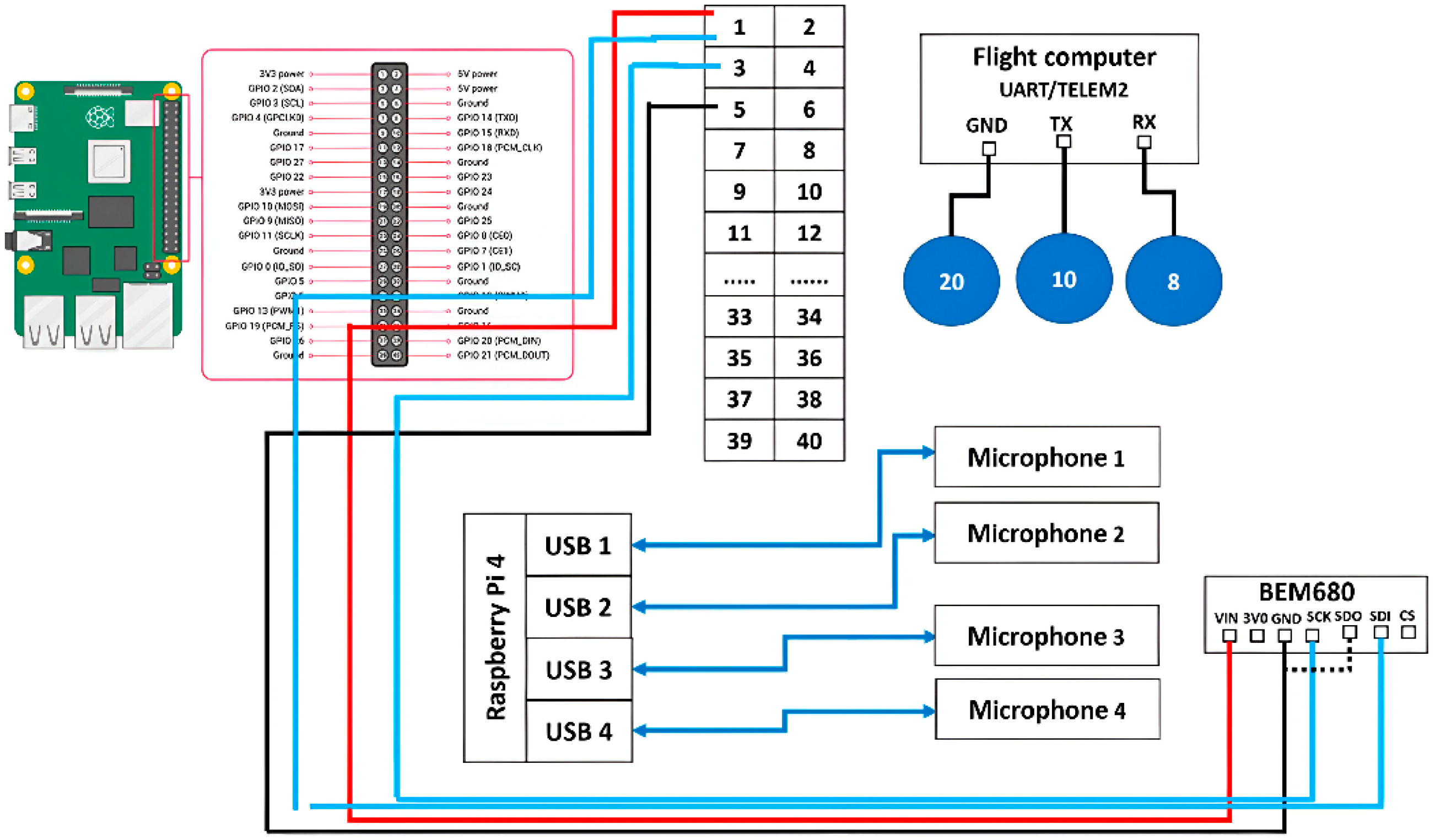
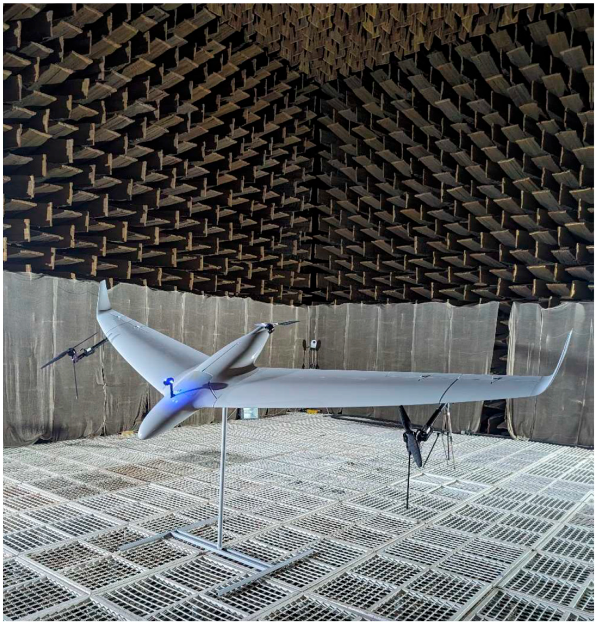
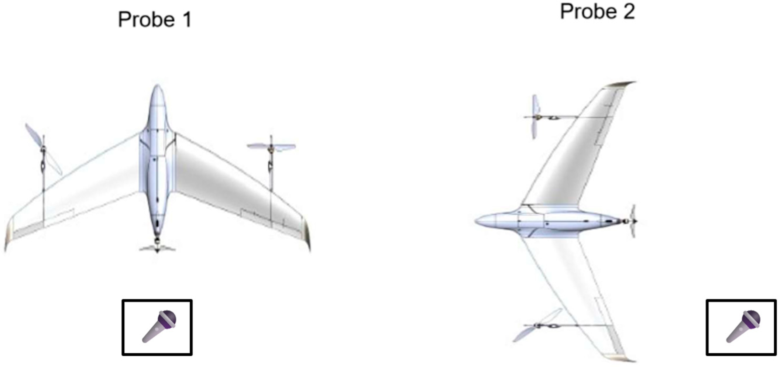
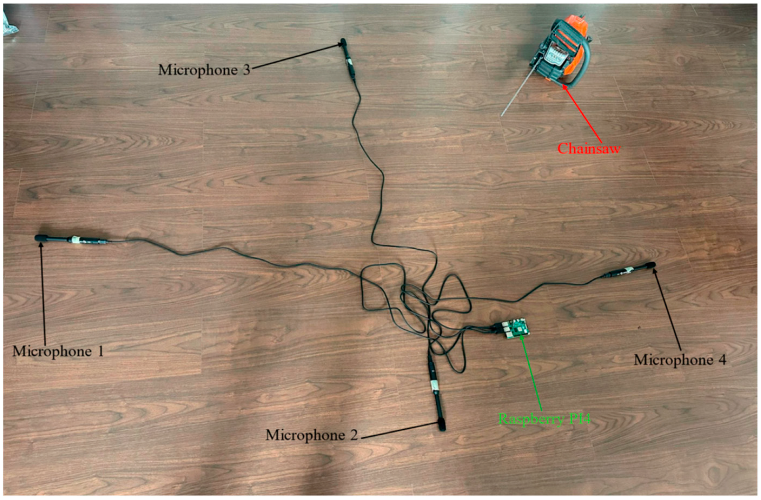
2.1. UAV Platform and Hardware Configuration

The unmanned aerial vehicle (UAV) developed in this study is a hybrid platform that combines the vertical takeoff and landing (VTOL) capabilities of rotary-wing aircraft with the efficiency of fixed-wing flight. This design facilitates operations in diverse terrains, including forested areas where runway infrastructure is unavailable [22,23]. The airframe is constructed using fiber-reinforced polymer composites, optimizing the balance between structural integrity and weight reduction. The aerodynamic configuration has been refined to achieve a cruise speed of approximately 50 km/h and a flight endurance exceeding 3 h, making it suitable for extended surveillance missions [24]. A tri-rotor configuration was selected after comparative analyses with quadcopter systems, offering advantages in terms of mechanical simplicity and energy efficiency. The VTOL system has been optimized to vectorize thrust, enhancing performance during transitions between hover and cruise flight modes. The UAV is equipped with payload bays designed to accommodate various sensors, including those for meteorological data collection. For the specific application of acoustic surveillance, a dedicated sound detection system has been integrated to identify chainsaw noise, aiding in the prevention of illegal deforestation activities. The onboard electronics suite includes components necessary for flight control, data acquisition, and real-time processing of sensor inputs. Power management systems have been implemented to ensure optimal energy distribution, supporting the UAV’s extended flight duration and the operation of its sensor payloads. To enhance the effectiveness of the acoustic detection system, noise mitigation strategies have been employed, including the strategic placement of sensors away from propulsion sources and the use of materials and structural designs that minimize acoustic interference from the UAV’s own systems [24].
Figure 1 shows a schematic representation of the UAV platform illustrating the placement of four microphones (Mic. 1 to Mic. 4) relative to the symmetry axis. The configuration was determined through a systematic analysis of acoustic performance and aerodynamic considerations.
Figure 2 provides a detailed overview of the system’s electronic configuration, highlighting the seamless integration of acoustic sensors, signal processing, and control modules. The core of the system is a Raspberry Pi 4, functioning as the primary processing unit, which receives audio inputs from four strategically positioned microphones. These microphones are connected via an analog-to-digital converter (ADC), ensuring high-fidelity signal acquisition. The captured audio signals are processed in real-time using a convolutional neural network (CNN) model optimized for sound classification, enabling the identification of target acoustic events, such as chainsaw noise. The processed acoustic data are transmitted to the UAV’s flight control system through a UART (Universal Asynchronous Receiver-Transmitter) interface, facilitating immediate system response based on detected sounds [24].
The electrical architecture also incorporates a meteorological sensor, providing supplementary environmental data to enhance acoustic analysis accuracy. Power distribution is efficiently managed, with the acoustic module directly supplied by the UAV’s primary power circuit, ensuring operational stability. This design guarantees that the acoustic system maintains optimal performance under various flight conditions, supporting precise sound detection and classification in real-time.

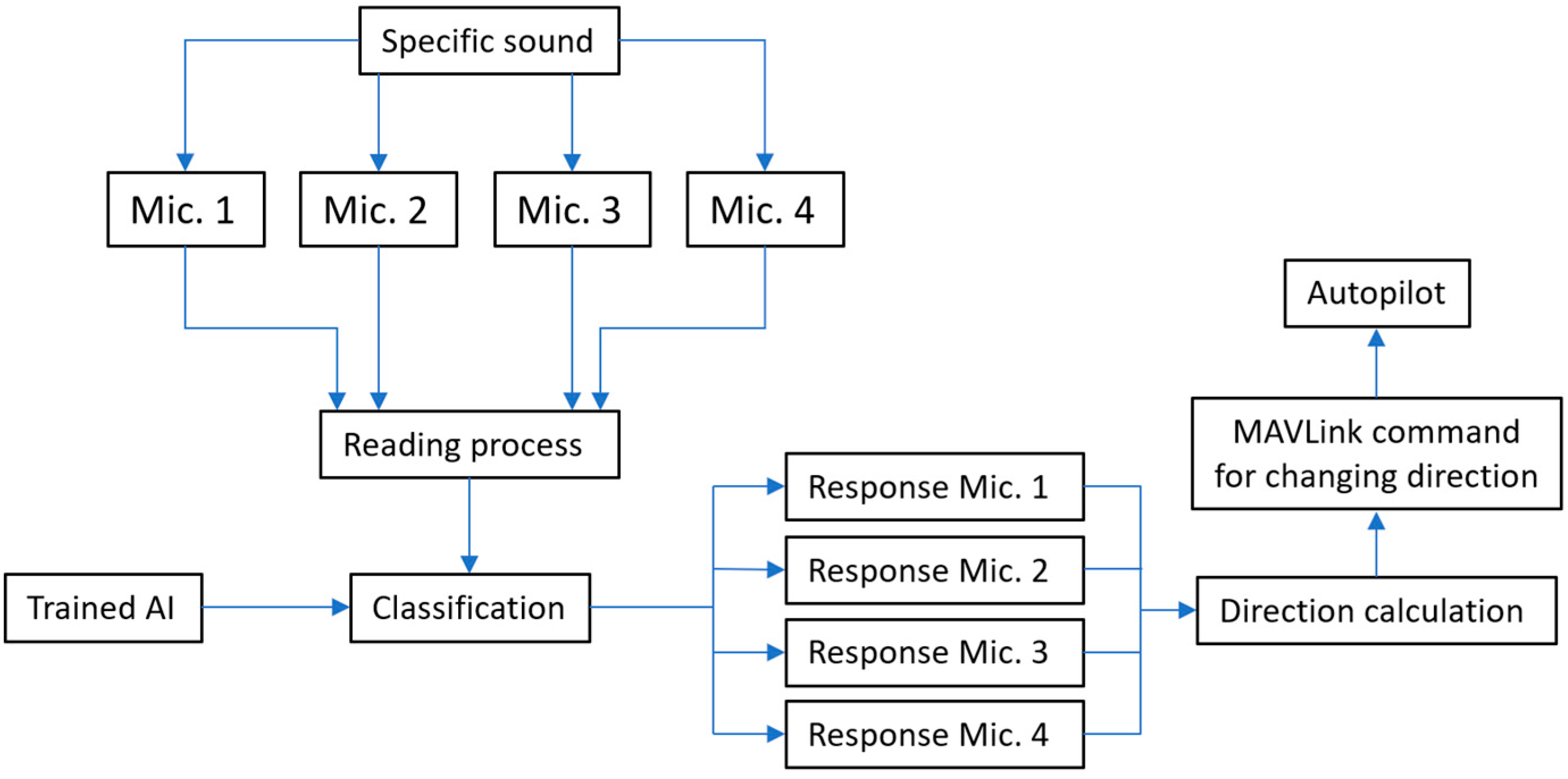
2.2. Algorithm Development

Figure 3 illustrates the architecture of an acoustic-based direction estimation and control system designed to enable autonomous navigation in response to specific sound stimuli. The system employs an array of four spatially distributed microphones to capture acoustic signals from the environment. Upon detection of a predefined sound event, each microphone records the signal with slight temporal differences due to their relative positions. These signals are then passed through a centralized preprocessing unit, where synchronization, noise filtering, and feature extraction are performed to prepare the data for analysis. The processed acoustic inputs are subsequently fed into a trained artificial intelligence (AI) model tasked with classifying the spatial origin of the sound based on learned temporal and spectral patterns. The model outputs response profiles corresponding to each microphone, which are interpreted by a directional estimation module to compute a vector indicating the likely direction of the sound source. This directional information is then converted into a standardized MAVLink command, which is transmitted to the vehicle’s autopilot system to adjust its orientation accordingly.
The integration of AI-based classification with real-time acoustic sensing enables robust and low-latency navigation decisions, making the system highly suitable for applications in GPS-denied environments, interactive robotics, and sound-guided search and rescue operations.

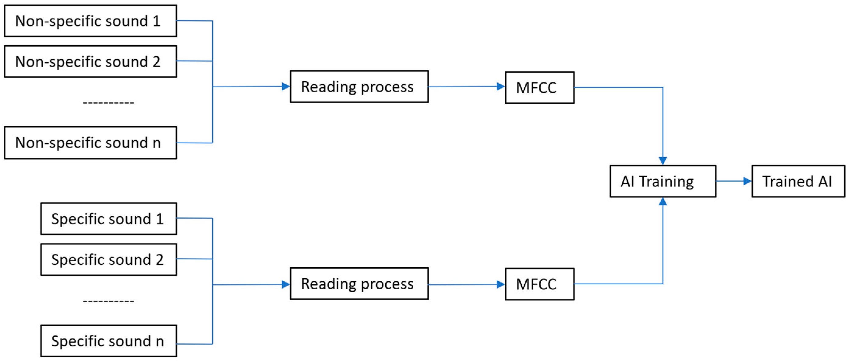
2.2.1. Training the Artificial Intelligence Model for Specific Sound Classification

The first stage of the proposed software system focuses on training a convolutional neural network (CNN) capable of automatically distinguishing between specific sounds associated with illegal logging (e.g., chainsaws, electric/thermal saws) and non-specific environmental sounds (e.g., wind, birds, power tools). This stage represents the “learning phase” of the AI system and is based on the processing of audio files using Mel Frequency Cepstral Coefficients (MFCCs), a widely used feature extraction method for audio classification tasks.
The chainsaw recordings used for training the AI classification model were sourced from a publicly available dataset comprising audio samples captured under various environmental conditions. These include differences in recording distance, background ambient noise, and tool operation settings, which help to ensure greater model robustness in non-controlled field scenarios.
Figure 4 illustrates the logical flow of the training pipeline, detailing how labeled audio inputs are processed and used to train the neural network.
The dataset is organized into two distinct classes:
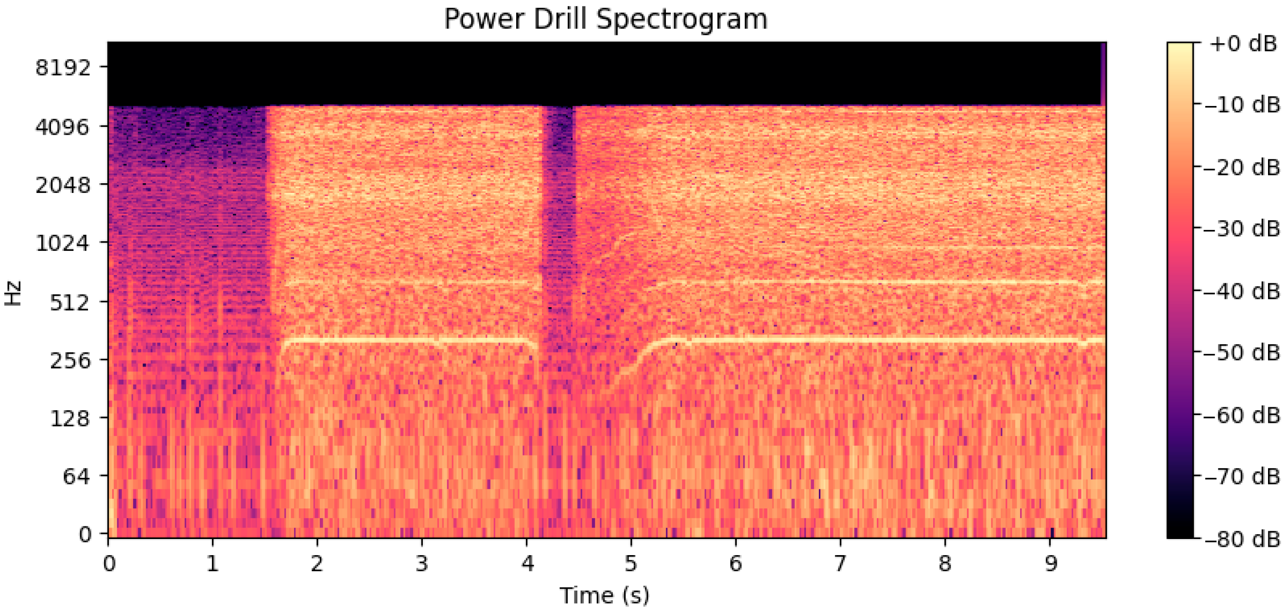
  • Non-specific sounds (negative class): environmental and mechanical sounds such as birds, wind, and traffic, including the sound of a power drill—intentionally added due to its frequency spectrum being similar to a chainsaw;
  • Specific sounds (positive class): recordings of chainsaws, electric saws, and thermal saws, typically used in tree-felling operations.
All files are read using a Python, version 3.10, based tool and processed uniformly to extract MFCCs, which serve as the input features for model training. Raw audio signals are first transformed into a set of acoustic features suitable for machine learning. To achieve this, we employ Mel-Frequency Cepstral Coefficients (MFCCs), which capture the perceptually relevant spectral characteristics of sound.
Let x ( t ) denote the discrete-time audio signal. The MFCC coefficients are computed by applying a short-time Fourier transform, followed by a Mel-scaled filter bank and logarithmic compression. The cepstral coefficient for Mel band m at time frame n is defined as:
C m , n = l o g k = 1 K X k n 2 · H m k
The MFCC value C m , n is computed by applying the Mel filter H m k to the spectral amplitude X k n , capturing perceptually relevant frequency information at each time frame.
To reduce dimensionality and produce a fixed-length feature vector suitable for classification, the MFCCs are averaged over the time dimension:
f m = 1 T n = 1 T C m , n
Resulting in a compact representation f = f 1   , f 2   , f 3 , , f M   , where M is the number of cepstral coefficients retained (typically 13–20).
The extracted feature vectors f   serve as input to a Random Forest classifier, a widely used ensemble method composed of multiple decision trees. Each decision tree T i   in the forest provides a prediction, and the final classification is obtained through majority voting or probabilistic averaging.
P y = 1   |   f = 1 N i = 1 N T i   f
where:
  • f R M   is the MFCC feature vector;
  • y 0 , 1   is the output label (0 = non-specific, 1 = specific);
  • N is the number of trees in the forest.
Each tree is trained by recursively partitioning the feature space using the Gini impurity criterion at each node:
G = 1 c = 1 C p c 2
where p c is the proportion of samples from class c at a given node, and C = 2 in the binary classification task.

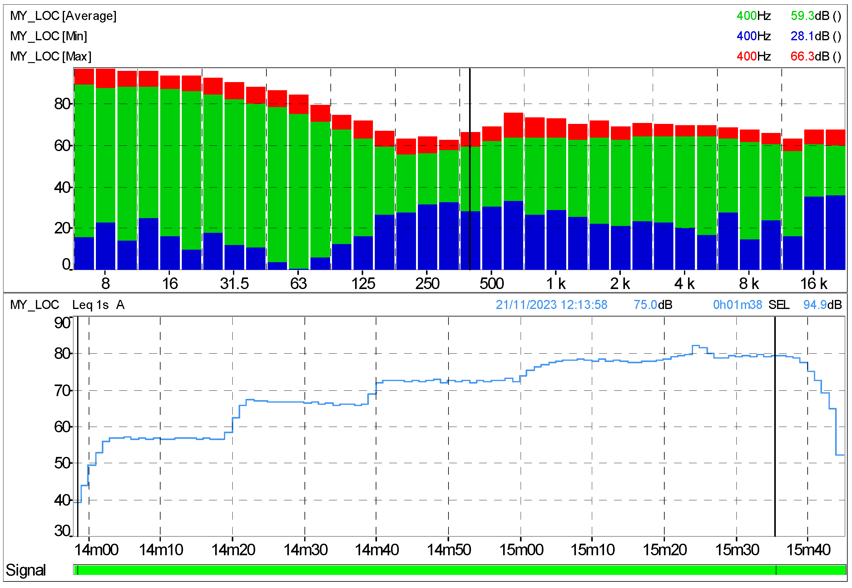
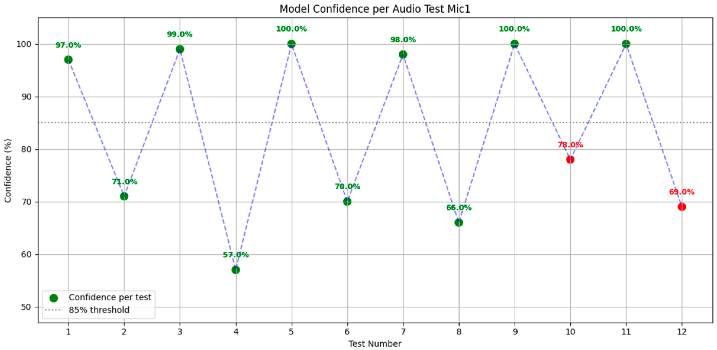
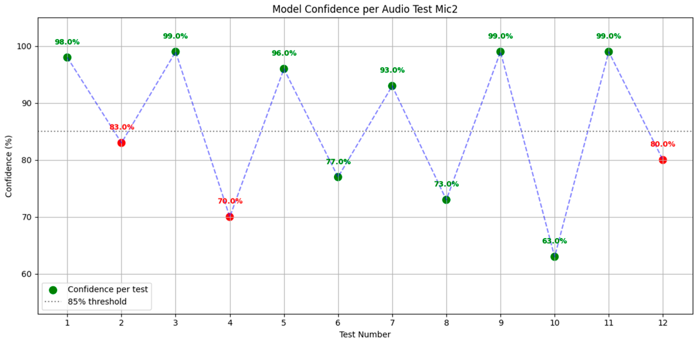
2.2.2. Experimental Validation

To validate the correct functionality and robustness of the developed software system, a series of controlled ground-level tests were conducted. The primary objective of these tests was to assess the AI model’s ability to distinguish between acoustically similar and dissimilar sound categories under consistent recording conditions.
The first phase of validation involved the generation of spectrograms corresponding to four distinct sound categories:
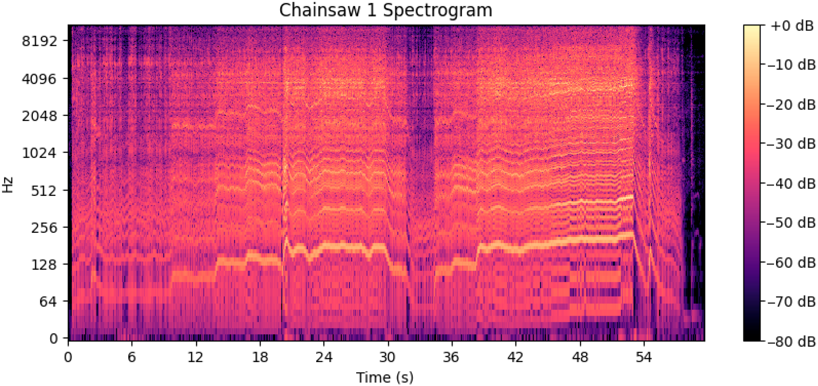
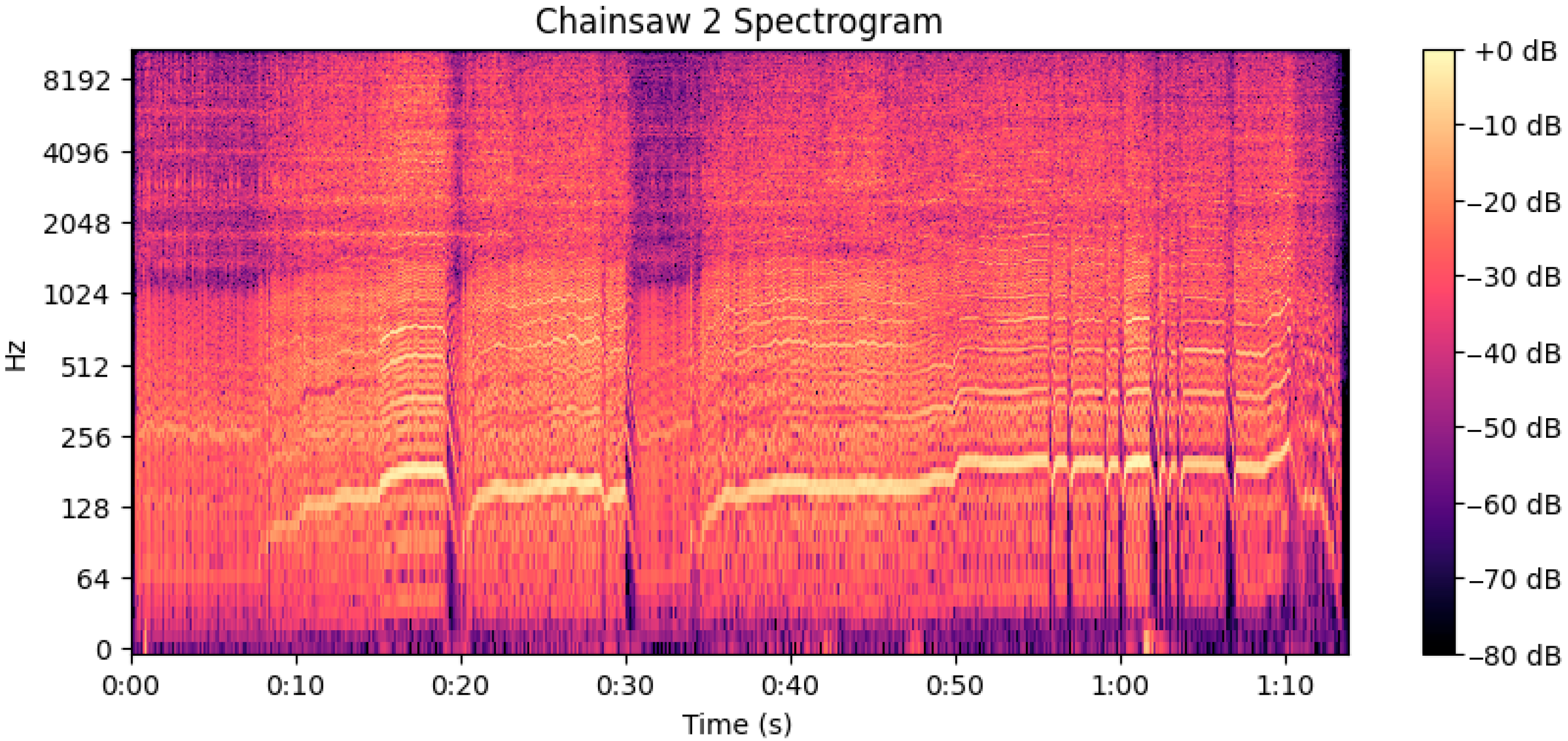
  • Gasoline-powered chainsaw sounds;
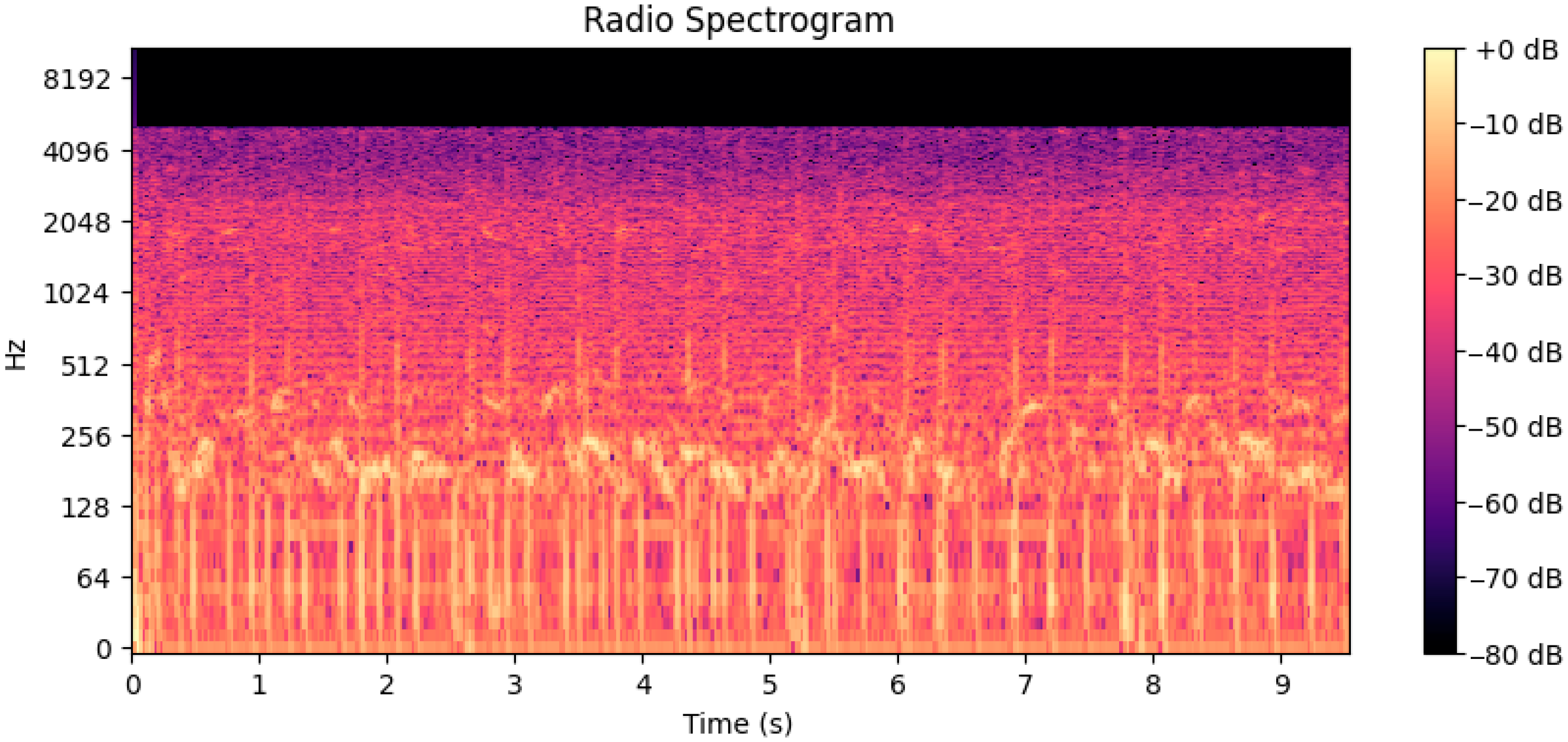
  • Radio sound;
  • Power drill sounds;
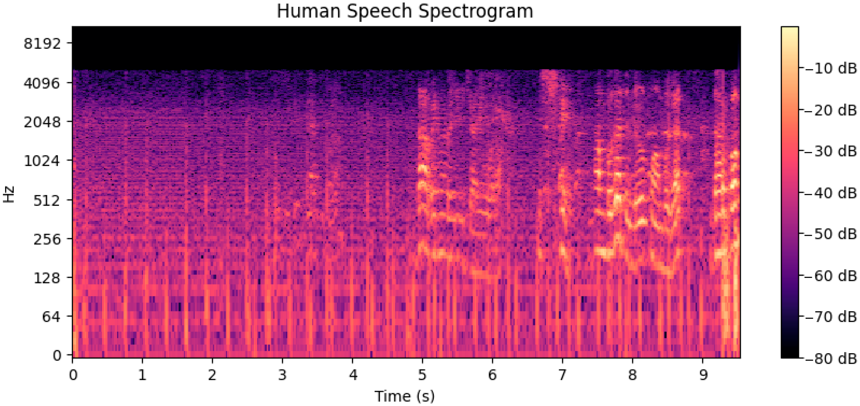
  • Human voice recordings.
The sound samples for the first category were produced using two different models of gasoline chainsaws:
  • Ruris Expert 351, with an engine power of 1.6 kW and a displacement of 45 cm3;
  • Husqvarna 135 Mark II, also rated at 1.6 kW and a displacement of 38 cm3;
All chainsaw sound recordings were carried out in a fully anechoic chamber at COMOTI–Romanian R&D Institute for Gas Turbines (Bucharest, Romania), ensuring minimal environmental noise interference and high fidelity of spectral data.
The recordings were processed to generate high-resolution spectrograms using a custom-built Python 3-based software tool developed by COMOTI specifically for acoustic signal analysis. These spectrograms provide a time-frequency representation of the acoustic signal, enabling a detailed inspection of the harmonic and transient characteristics unique to each sound type.
To produce the resulting spectrograms, the following methodology was employed, based on frequency-domain analysis of audio signals using the Short-Time Fourier Transform (STFT). The recorded WAV audio signal was first sampled and, if originally in stereo format, converted to a single-channel (mono) representation to simplify processing. The signal was then divided into successive, fixed-length frames—typically between 20 ms and 50 ms—allowing analysis of the time-varying spectral content. Each frame was multiplied by a windowing function, specifically a Hann window, to reduce discontinuities at the frame edges and minimize spectral leakage [25]. The Hann window, a tapered cosine function, is defined as:
w n = 0.5 1 c o s 2 π n N 1
where N is the window length and n ranges from 0 to N 1 . This tapering results in a smoother transition between frames and enhances frequency resolution.
The windowed frames were then transformed using the Fast Fourier Transform (FFT), converting the time-domain signal into its frequency-domain representation. The FFT output, denoted X k , contains the complex frequency components for each time segment. The power spectrum was obtained by computing the squared magnitude of the FFT:
P k = X k 2
This power spectrum was converted to a logarithmic scale, using decibels, to reflect human perception of sound intensity:
S k = 10 · l o g 10 P k + ε
where ε is a small positive constant to prevent taking the logarithm of zero.
The resulting matrix—with frequency on the vertical axis, time on the horizontal axis, and intensity values in decibels forming the matrix elements—constitutes the spectrogram. This spectrogram was visualized using a color scale (colormap), providing an intuitive graphical representation of how the signal’s energy is distributed over frequency and time, Figure 5.
To reduce the likelihood of misclassification by the AI-based acoustic recognition system, a comparison was made between two tools with acoustically similar signatures: a chainsaw and a power drill. As shown in Figure 6 and Figure 7, both spectrograms highlight time-frequency characteristics relevant for machine learning.
The chainsaw spectrogram exhibits a dynamic and complex structure, with rich harmonics extending above 4 kHz and clear variations over time. These are typical of combustion engines, where fluctuations in speed and load create shifting spectral patterns. In contrast, the power drill shows a more stable and periodic structure, with energy concentrated mainly below 1 kHz and distinct activation intervals.
The generated spectrograms were analyzed both visually and quantitatively to verify the model’s capacity to differentiate between specific (chainsaw) and non-specific (music [Figure 8], drill, voice [Figure 9]) sound categories. The chainsaw recordings served as positive control cases, while the remaining three categories provided negative examples—some of which (e.g., power drill) are acoustically similar to chainsaws and pose a greater classification challenge.

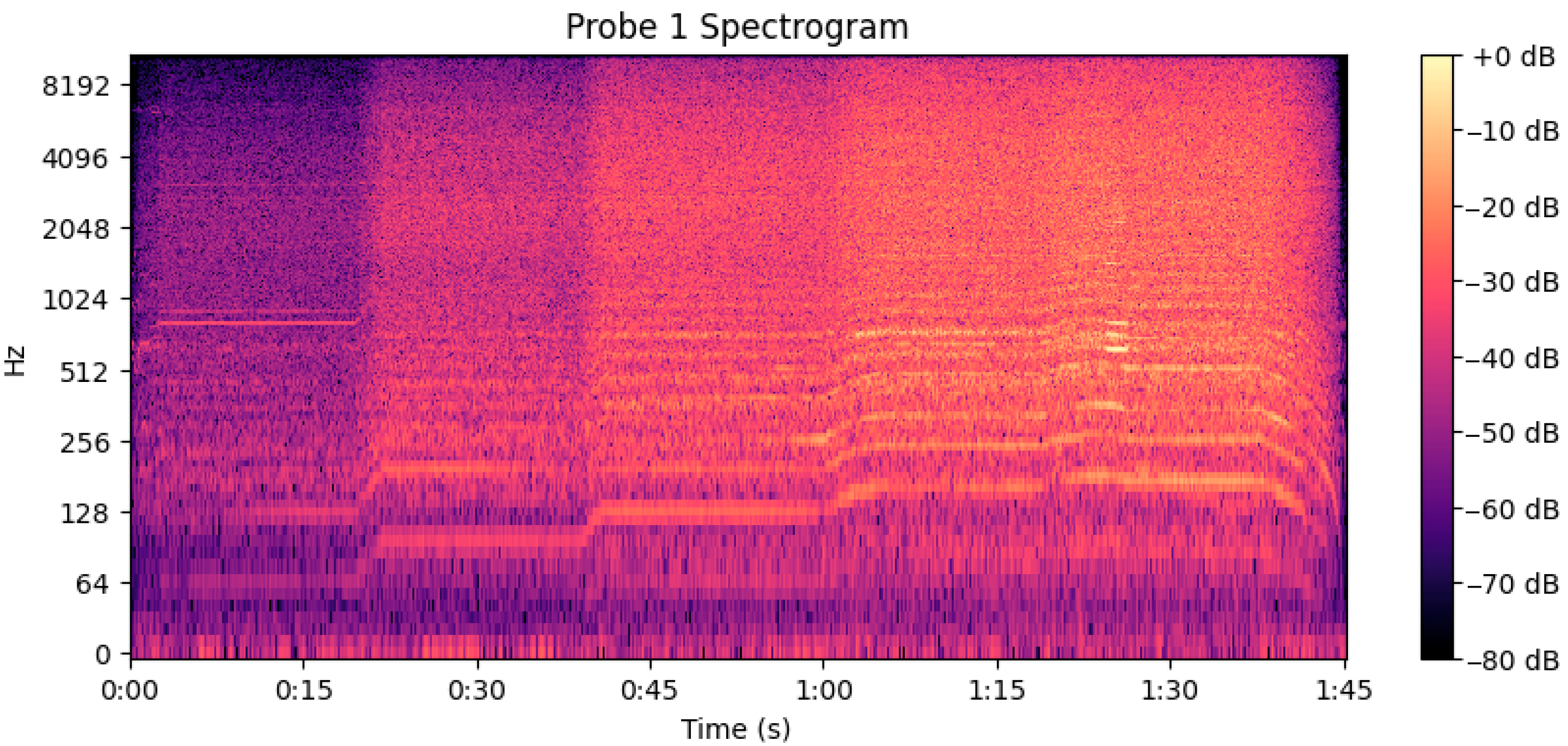
2.2.3. Noise Canceling for Propulsion Sound Isolation
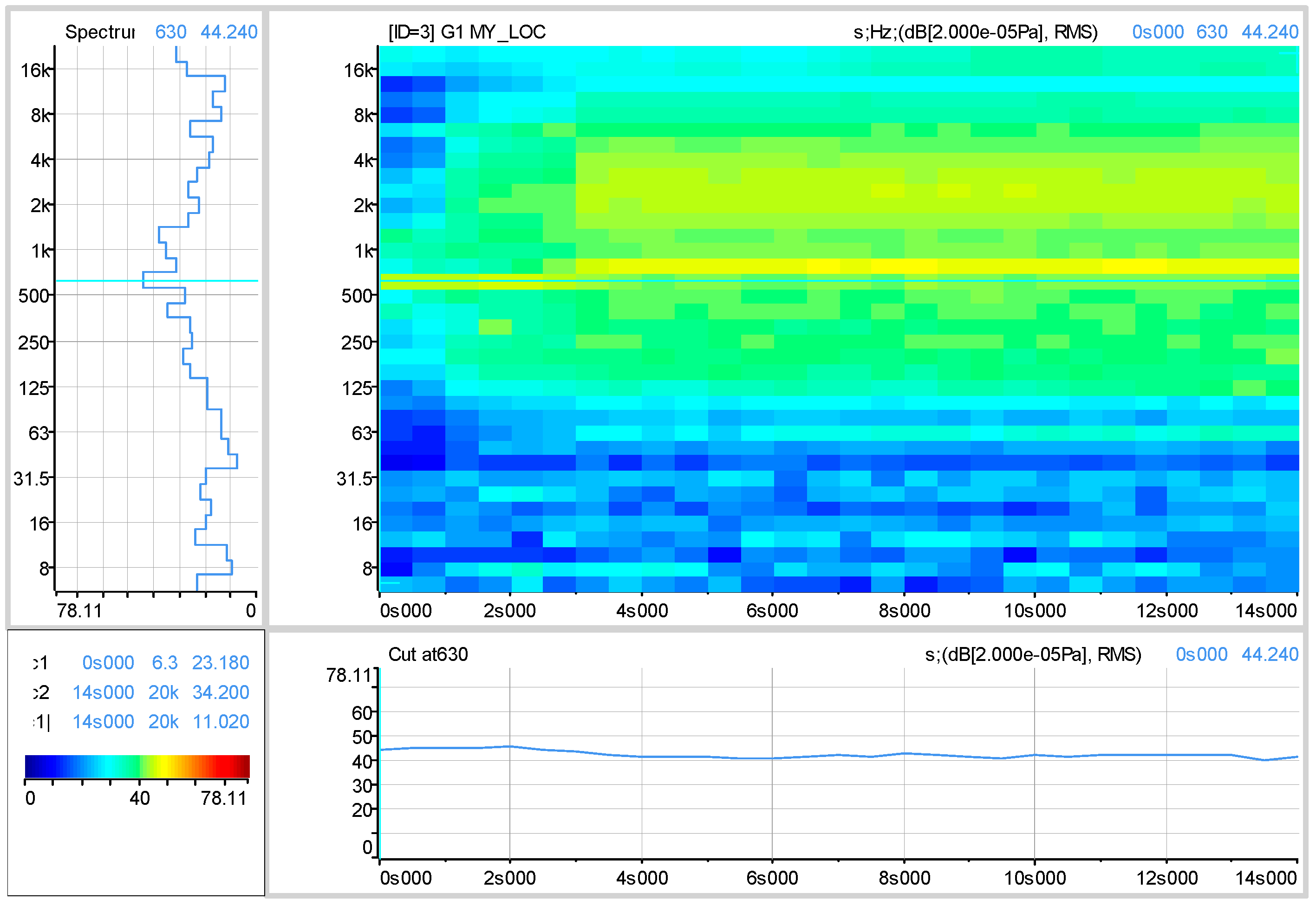
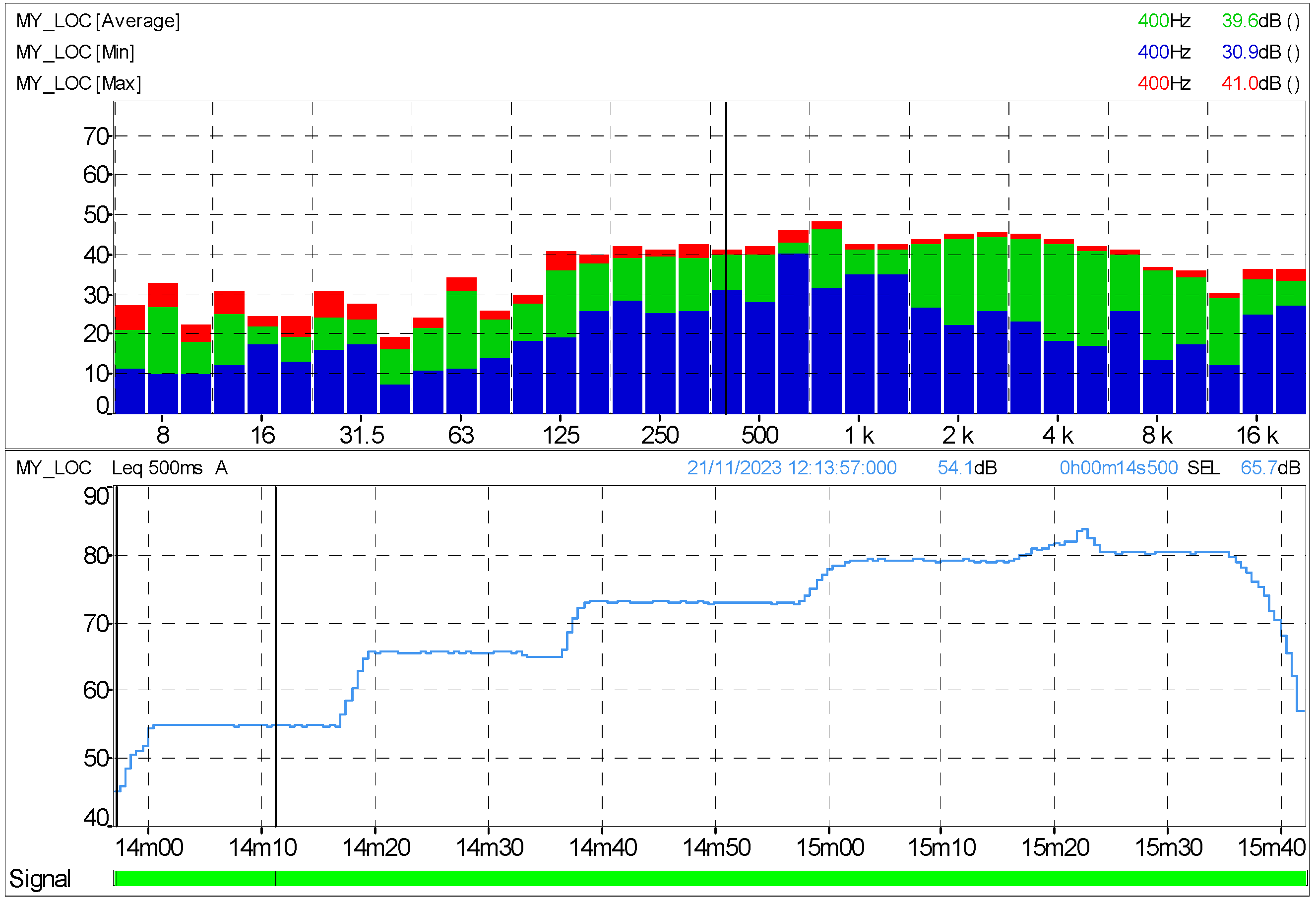
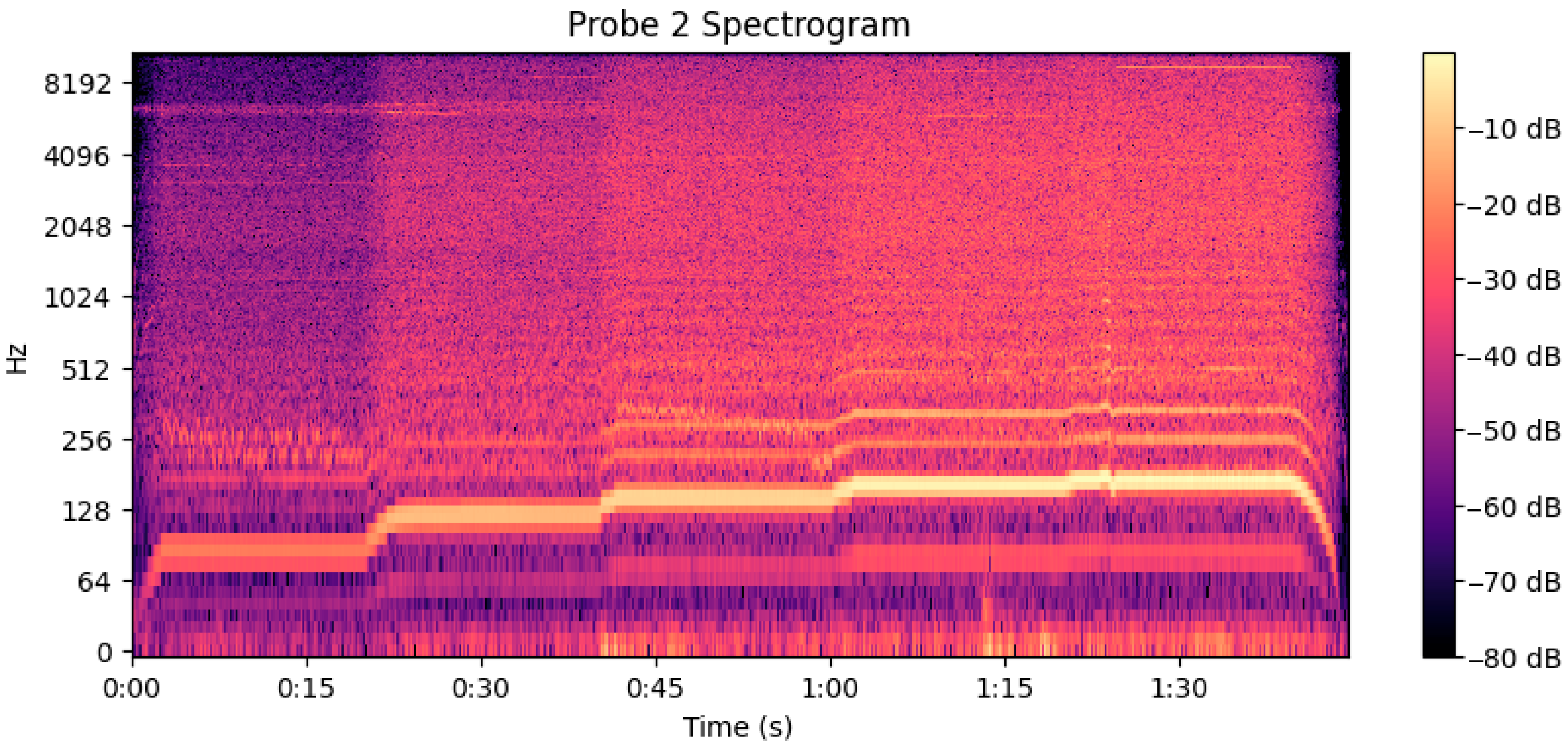
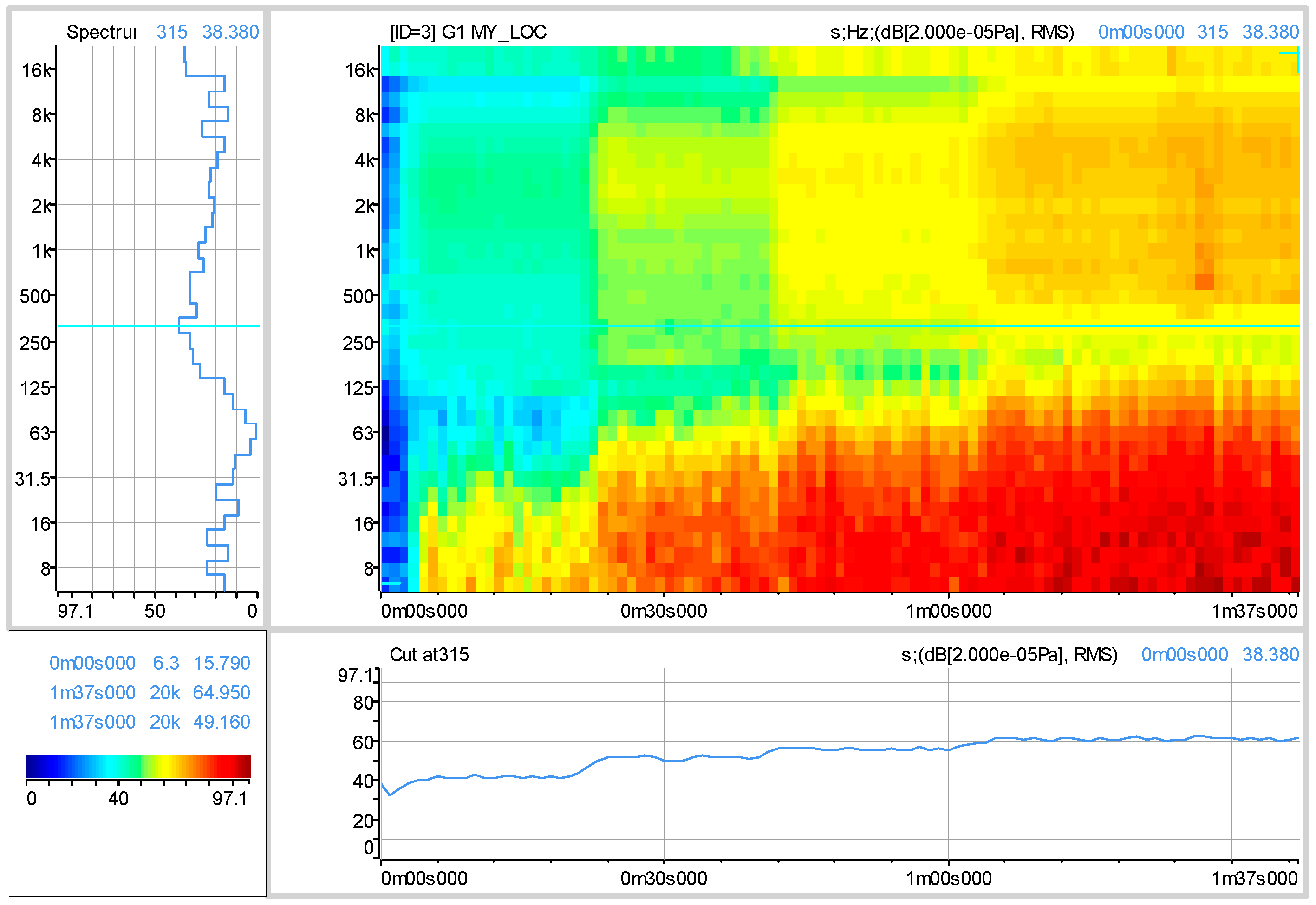
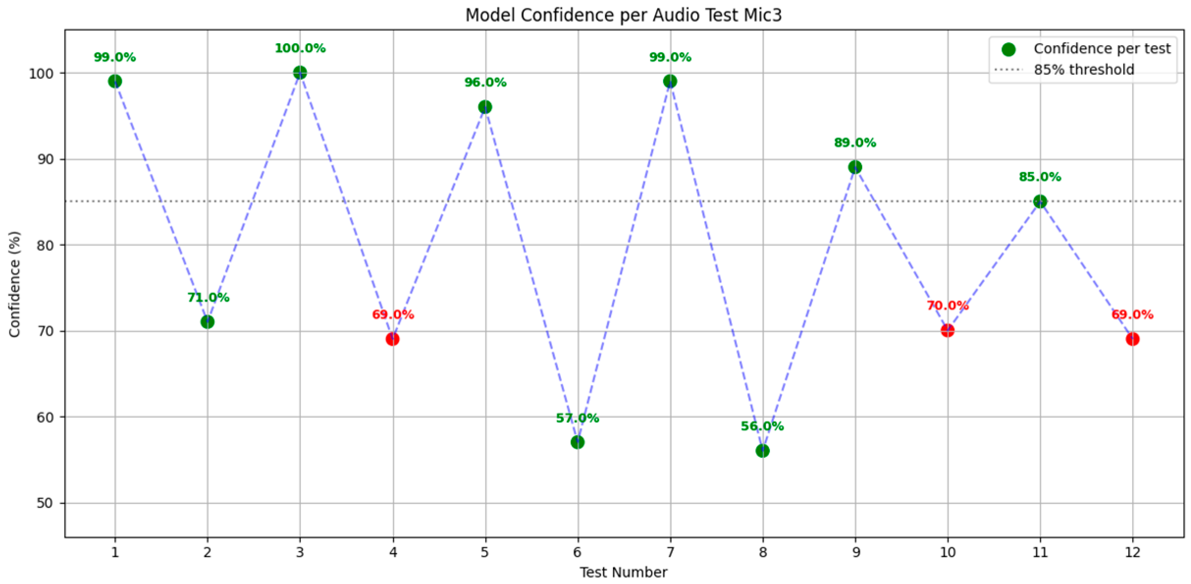
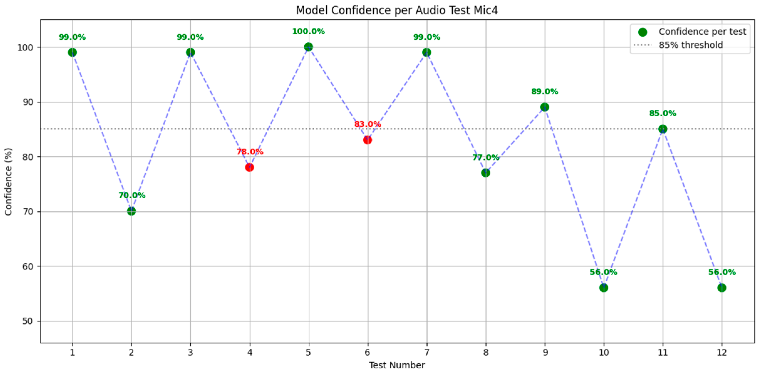
In the context of UAV (Unmanned Aerial Vehicle) acoustic analysis, one of the primary challenges encountered is the presence of persistent background noise generated by the propulsion system. The tested drone operates in two distinct flight modes: hovering and cruise. The cruise phase is of particular interest for acoustic measurements, as it presents a lower energy consumption state, with the side-mounted wing motors completely deactivated and only the rear propulsion motor operating at 40–60% of its maximum capacity. Although this configuration minimizes overall acoustic output, the electric motor noise remains a dominant component in the recorded soundscape. To enable accurate detection of external, it is crucial to isolate and suppress the recurring motor-generated noise.
As a prerequisite, the spectral fingerprint of the electric motor was recorded in a controlled environment—an anechoic chamber, as shown in Figure 10. This setup ensures a pure capture of the motor’s acoustic profile, free from reverberations or external interference. The recorded motor signal serves as a reference for developing a digital filtering method capable of selectively removing this component from in-flight recordings.
To evaluate the acoustic footprint of the propulsion system and enable accurate noise characterization for subsequent filtering and AI-based recognition tasks, two controlled acoustic tests were conducted under repeatable conditions. These tests were designed to isolate the directivity and spatial propagation characteristics of the electric motor noise emitted by the UAV.
In both cases, the recording setup involved a stationary microphone placed at a fixed location in the test environment, while the UAV’s orientation was modified between tests. The two configurations are illustrated in Figure 11.
Test 1 (Probe 1): The UAV was positioned facing forward, with its longitudinal axis aligned perpendicularly to the microphone. In this configuration, the microphone was located directly behind the drone, along the axis of the rear propulsion motor. This setup captured the full extent of the motor’s rearward noise emission, simulating a scenario where the drone flies away from an observer or receiver.
Test 2 (Probe 2): The UAV was rotated 90° relative to its original orientation, such that one wing was aligned along the axis to the microphone. The microphone’s position remained unchanged. This lateral orientation allowed assessment of the motor’s acoustic emission profile from the side, providing insights into directional variations in sound intensity.
Both tests were carried out with the drone powered on and the rear motor operating in cruise conditions (i.e., at 40–60% of maximum power), replicating the acoustic profile expected during steady-state flight. No external noise sources or background interferences were introduced during the recordings, ensuring that the captured data reflected the UAV’s intrinsic acoustic signature. This two-angle approach allowed for comparative analysis of the motor’s sound distribution and served as input for noise suppression strategies in post-processing, including the identification of dominant frequencies and propagation patterns that could be algorithmically canceled in real-time or offline.
Figure 12 presents the spectrogram of the acoustic signal recorded by Probe 1, illustrating the time-frequency evolution of the noise generated by the drone electric motor. The spectrogram clearly shows a series of harmonic components that gradually shift upwards in frequency over time, corresponding to a steady increase in the propeller’s rotational speed. The tonal structure is well defined, with multiple harmonics visible up to several kilohertz, indicating a stable and periodic acoustic emission characteristic of electrically driven rotors.
Figure 13 presents the calibrated spectrogram of Probe 1, where the acoustic signal is displayed in absolute units of sound pressure level (dB SPL, re 20 µPa). In contrast to the relative spectrogram shown in Figure 12, which emphasizes the harmonic structure and dynamic range of the signal, this calibrated representation provides a quantitative assessment of sound intensity over time and frequency. The color scale, located in the lower left corner of the figure, represents SPL values ranging from approximately 11 dB (deep blue) to 78 dB (dark red). This visual scale enables direct interpretation of the acoustic energy distribution across the frequency domain, with warmer colors (yellow to red) indicating higher intensity levels. By expressing the data in calibrated physical units, the spectrogram allows for objective comparison against standard acoustic thresholds and enhances the interpretability of tonal and broadband features in the recorded signal.
The top-right panel displays a 1/3-octave band spectrogram, revealing a dominant energy concentration around 500–1000 Hz, consistent with the harmonic content observed previously. However, in this view, the data is normalized to real-world pressure levels, enabling direct comparison with acoustic exposure thresholds or regulatory limits. The left panel shows the mean frequency spectrum, where a peak at approximately 630 Hz confirms the tonal dominance of the blade-passing frequency. The bottom panel tracks the temporal evolution of the SPL at 630 Hz, indicating a relatively stable amplitude over time with slight variations, matching the tonal components observed in Figure 12.
Figure 14 illustrates the broadband acoustic level characteristics recorded by Probe 1, using two complementary visualizations. The upper panel presents the frequency distribution of sound pressure levels (SPL) in octave bands, showing minimum (blue), average (green), and maximum (red) values. A spectral peak is observed in the 500 Hz to 2 kHz range, consistent with tonal components linked to propeller rotation.
Figure 15 shows the spectrogram recorded by Probe 2, positioned at a different location relative to the drone. While similar harmonic content is observed, the lower frequency bands (up to ~500 Hz) appear more pronounced and better resolved, suggesting stronger coupling of the microphone with the drone’s low-frequency components. The clearer step-like progression of tonal bands over time further supports the identification of discrete RPM increases. This recording complements Probe 1 by offering enhanced resolution in the low-frequency range.
Figure 16 presents the calibrated spectrogram of Probe 2, where the acoustic signal is displayed in absolute units of sound pressure level (dB SPL, re 20 µPa). In contrast to the relative spectrogram shown in Figure 15, which emphasizes the harmonic structure and dynamic range of the signal, this calibrated representation provides a quantitative assessment of sound intensity over time and frequency. The accompanying color scale, located in the lower left corner of the figure, reflects the SPL magnitude, ranging from approximately 11 dB (dark blue) to 78 dB (dark red). These color gradients correspond to the varying intensity levels within the recorded signal, with brighter tones indicating stronger acoustic emissions. This calibrated format enhances the precision of spectral interpretation and facilitates comparison with known acoustic exposure limits or environmental noise baselines.
The top-right panel displays a time-frequency spectrogram in calibrated units, showing a gradual increase in acoustic energy, particularly between 31.5 Hz and 500 Hz.
This spectral rise over the 1-min and 37-s duration indicates a consistent growth in the drone’s propulsion activity, with high-energy tonal components becoming increasingly dominant toward the end of the recording. The left panel shows the averaged sound pressure level across frequency bands, where a clear spectral peak is identified around 315 Hz, representing the main tonal component associated with the blade-passing frequency. The bottom panel provides a time-domain profile of the SPL at 315 Hz, illustrating a steady increase in level from approximately 35 dB to over 65 dB SPL. This reflects the temporal evolution of the tonal energy and supports the detection of propeller acceleration phases.
Figure 17 presents the calibrated acoustic level analysis recorded by Probe 2, using octave-band representation (top) and time-based equivalent level (bottom). The upper panel shows the minimum (blue), average (green), and maximum (red) sound pressure levels across octave bands from 8 Hz to 16 kHz. The spectrum reveals a dominant low-frequency content, particularly below 63 Hz, where the SPL values exceed 80 dB, indicating significant tonal and broadband low-frequency energy likely generated by the drone’s propulsion system. A spectral dip appears around 250 Hz, followed by moderate SPL levels between 500 Hz and 8 kHz.
While the current noise suppression approach was based on reference recordings in an anechoic chamber specific to the tested UAV configuration, we acknowledge that its transferability to other hardware platforms or environmental contexts may be limited. Variations in motor type, propeller design, and structural dynamics can result in different acoustic signatures that require platform-specific profiling. Additionally, environmental noise sources such as wind and terrain reflections can further reduce the effectiveness of static spectral filtering. Future development will explore adaptive noise suppression methods that can dynamically adjust to changes in UAV hardware and environmental conditions using real-time spectral modeling or ML-based denoising algorithms.

3. Results

To evaluate the performance of the acoustic localization system under controlled conditions, a series of ground-based experiments were carried out using the configuration depicted in Figure 18. The test platform consisted of four omnidirectional condenser microphones arranged in a non-symmetrical planar array and connected to a Raspberry Pi 4 unit responsible for real-time audio acquisition and processing. The setup was deployed in a quiet indoor environment with reflective flooring and minimal ambient noise.
As the acoustic target, a two-stroke gasoline-powered chainsaw was operated at idle and partial throttle settings to generate a broadband, high-intensity signal source. The chainsaw was manually positioned at multiple azimuth angles relative to the center of the array (e.g., 0°, 45°, 90°, 135°, etc.), simulating different incident sound directions. For each orientation, several measurements were repeated to account for variability in signal propagation and mechanical noise.
To assess the robustness and generalization capacity of the trained classifier, a series of controlled live evaluations were conducted using audio data recorded from two distinct classes: specific sounds (chainsaw) and non-specific sounds (ambient or unrelated acoustic sources). A total of 12 tests were performed in alternating order, one specific, followed by one non-specific, utilizing real-time recordings from each microphone. For each sample, the model output was analyzed not only in terms of classification outcome, but also via the associated confidence probability, expressed as a percentage.
The graphical results shown in the following figures (Figure 19, Figure 20, Figure 21 and Figure 22) demonstrate that the majority of predictions met or exceeded the predefined decision threshold of 85%, effectively confirming the reliability of the classification system under live operational conditions. Notably, a small number of samples were incorrectly classified (marked in red); however, their confidence levels remained below the threshold, thereby ensuring that non-specific sounds were still correctly rejected in the decision-making pipeline. This confirms that the threshold mechanism served as a protective layer, preventing false positives despite model uncertainty.
Moreover, these test iterations contributed to the model’s refinement process. By analyzing misclassifications with high certainty, targeted retraining was applied to improve the classifier’s discriminatory ability. This dynamic evaluation method not only provided a meaningful insight into real-world performance, but also supported the adaptive evolution of the AI through continuous exposure to varied acoustic environments.
Following the completion of the ground-based accuracy validation, the next phase involved testing the microphone array configuration during flight conditions to assess the angular resolution of the sound localization system. Figure 23 illustrates the spatial arrangement of the four microphones mounted on the UAV platform, which served as the basis for direction-of-arrival (DoA) estimation in airborne scenarios.
This configuration enabled real-time processing of acoustic signals in dynamic flight environments, allowing evaluation of the system’s localization performance under operational conditions.
For the purpose of distance estimation, Microphone 3 was selected as the reference point. From a mathematical standpoint, the angular constants ( θ ) assigned to each microphone are as follows: 0° for Microphone 3, 90° for Microphone 4, 180° for Microphone 2, and 270° for Microphone 1. Given these predefined θ values, the next step involves determining the distance d from the sound source to the closest microphone. This distance is computed according to the following relationship:
d = k A
where k is the proportionality constant serving as a calibration factor, and A represents the amplitude of the audio signal.
To estimate the direction of the sound source, each microphone is assigned a unit direction vector v i , defined in polar coordinates by the angle α i corresponding to the known position of Microphone i . Specifically, v i , indicates the direction from the center of the array toward Microphone i , and is given by
v i = c o s ( α i ) s i n ( α i )
Once all directional vectors have been obtained, their summation is required.
V = i = 1 4 v i
Thus, the resulting average angle is computed as:
α ¯ = t a n 1 V y , V x
where V y , V x represent the distance vectors projected onto the two coordinate axes.
Figure 24 illustrates the in-flight testing setup used to evaluate the acoustic localization performance of the UAV-mounted microphone array. The test involved a UAV equipped with four spatially distributed microphones, flying at a controlled altitude of approximately 10 m above a stationary ground-based sound source. The altitude was limited due to flight stability constraints associated with the UAV platform during hovering operations. As the acoustic emitter, a gasoline-powered chainsaw was selected for its consistent and broadband spectral output, suitable for time-difference-of-arrival (TDoA) and direction-of-arrival (DoA) estimation. During the test flights, multi-channel audio was recorded onboard at a sampling rate of 48 kHz. This experimental configuration enabled a realistic assessment of the localization algorithm’s performance under in-flight conditions, accounting for rotor-induced noise and environmental disturbances.
Table 1 summarizes the angular results obtained during the validation of the acoustic localization algorithm under static test conditions. The “Real Angle” column indicates the known positions of the stationary sound source relative to the UAV platform, while the “Calculated Angle” column shows the corresponding output of the localization process based on time-difference-of-arrival (TDoA) estimation and a vector transformation method. To quantitatively assess the performance of the sound localization algorithm, a set of static tests was conducted comparing the calculated direction-of-arrival (DoA) angles to known reference angles. The results, summarized in Table 1, reveal the system’s accuracy under controlled conditions. The absolute angular errors ranged from 2° to 10°, with an average of approximately 5.89° across all test cases.
A total of nine measurements were performed: two in each of the four quadrants of the circular reference frame, and one from a top-down (overhead) perspective. This spatial distribution ensured a balanced angular coverage, allowing the evaluation of the algorithm’s performance across a representative range of source positions.
These results confirm the practical limitations imposed by the acoustic hardware, particularly the microphones’ spatial resolution and sensitivity. Nonetheless, the overall angular accuracy is sufficient for UAV-integrated localization applications, providing a reliable foundation for subsequent dynamic testing phases.
Figure 25 illustrates the relationship between the known (real) angles of the sound source and those computed by the localization algorithm. The dashed line represents the ideal case (perfect estimation). Deviations from this line highlight the system’s angular error, which remains relatively small across the tested range, with good alignment in most cases.

4. Discussion

The experimental results presented in this study confirm the feasibility of integrating an acoustic classification and localization system into a fixed-wing VTOL UAV platform. The classification model demonstrated high reliability in identifying chainsaw noise under various conditions, including during flight. The in-flight tests validated the capacity of the microphone array to estimate the direction of arrival (DoA) using a purely geometric, non-AI-based approach. The mean absolute angular error of approximately 5.89°, and relative error typically under 8%, confirms that such systems are capable of achieving practical localization accuracy within the limitations of consumer-grade MEMS microphones. These findings are consistent with prior literature indicating similar levels of angular precision for low-cost sensor arrays in controlled environments [7,11].
The spectral signature of the electric propulsion system was found to be a dominant factor affecting signal clarity. The use of calibrated spectrograms and directional motor profiling (Probes 1 and 2) enabled the design of an adaptive filtering strategy for acoustic interference, which significantly enhanced the clarity of the environmental audio signal during flight. One limitation of the current system is the fixed geometry of the microphone array, which constrains localization performance to a planar 2D estimation. Additionally, wind-induced vibration and aerodynamic turbulence introduced minor signal distortions during flight, which could be mitigated by improved physical isolation or digital compensation techniques. Future research should explore the integration of adaptive beamforming methods, dynamic array reconfiguration, or even neural localization models to enhance angular resolution in real time. Further field trials in complex and cluttered environments (e.g., dense forest canopies) will also be essential to evaluate system robustness under more realistic acoustic conditions.
Although not the focus of this study, preliminary performance benchmarks were recorded during real-time classification on the embedded platform. The full inference pipeline including signal preprocessing and CNN execution required approximately 90–120 ms per frame, running on the Raspberry Pi 4′s CPU without GPU acceleration. Average CPU utilization remained under 60%, and the classification system was capable of processing up to 8–10 inputs per second. The total power consumption of the acoustic module, including the processing unit and audio interface, was estimated at 3.5–4 W, remaining well within the UAV’s power budget. Future work will incorporate formal benchmarking using standardized profiling tools.
One limitation of the current implementation is the absence of a comparative baseline analysis with alternative classification models. While the proposed CNN architecture was selected based on its favorable trade-off between accuracy and real-time feasibility on embedded hardware, future work will involve a detailed benchmark against classical machine learning models (e.g., MFCC + SVM) and lightweight deep learning architectures (e.g., CNN-lite or MobileNet) to evaluate performance, resource efficiency, and suitability for UAV deployment.
Although the system presented in this study is optimized for chainsaw detection, the underlying framework including spectrogram-based preprocessing and convolutional neural network classification is inherently adaptable to other acoustic events. By retraining the model with additional labeled data, the architecture can be extended to support a broader set of sound categories such as gunshots, alarms, emergency calls, or machinery malfunctions. This extensibility makes the platform suitable for a wide range of UAV-based monitoring applications beyond forestry surveillance.
From a regulatory perspective, the VTOL UAV platform used in this study has a maximum takeoff weight of 15 kg and, in accordance with EASA regulations, may be operated in category A3 airspace, provided that the pilot holds the appropriate remote pilot license. All flight tests were conducted in compliance with these legal requirements, specifically over sparsely populated forested areas, where the safety buffer and visibility conditions were fully respected.
Regarding privacy concerns, the use of continuous acoustic recording in this project does not raise significant issues, as the monitored environments were entirely natural, uninhabited zones with no exposure to private conversations or identifiable human activity. Consequently, the system’s deployment in such remote forestry applications is considered non-invasive and privacy-safe.

5. Conclusions

This work presents the design, implementation, and validation of a real-time, onboard acoustic classification and localization system for UAV platforms. A convolutional neural network trained on spectrogram-derived features successfully classified chainsaw sounds with high precision. Complementarily, a geometric localization method based on inter-microphone TDoA and vector transformation achieved angular estimation with an average absolute error below 6°, confirming the system’s suitability for detecting and tracking acoustic events such as illegal logging.
The methodology was validated through ground and flight tests, using a four-microphone array and a gasoline-powered chainsaw as the target sound source. In-flight tests were performed at a low altitude of 10 m to ensure UAV stability. The system proved effective even under rotor-induced noise and environmental variability, particularly due to the noise-canceling module based on spectral fingerprinting of the propulsion system.
Although the localization accuracy is constrained by the hardware limitations of MEMS microphones, the system demonstrates strong potential for deployment in aerial acoustic surveillance missions. Future developments will aim to reduce angular error further through algorithmic optimization and sensor fusion, enabling autonomous navigation and sound-tracking capabilities in real-world operational scenarios.

6. Patents

A Romanian application was filled at the OSIM—State Office for Inventions and Trademarks, application RO138102A0, registered on 30 April 2024.

Author Contributions

Conceptualization, G.-P.B., M.D. and T.-F.F.; methodology, G.-P.B. and M.D.; software, T.-F.F. and M.D.; validation, D.-E.C., T.-F.F. and M.D.; formal analysis, G.-P.B. and M.D.; investigation, T.-F.F. and D.-E.C.; resources, G.-P.B. and M.D.; data curation, M.C.; writing—original draft preparation, G.-P.B.; writing—review and editing, M.D. and M.C.; visualization, G.-P.B.; supervision, T.-F.F.; project administration, T.-F.F. and G.-P.B.; funding acquisition, T.-F.F. All authors have read and agreed to the published version of the manuscript.

Funding

This research was carried out under the “Nucleu” Program, Grant no. 31N/2023, Project PN 23.12.03.01, funded by the Romanian Ministry of Research, Innovation and Digitization. The APC was also funded by the Romanian Ministry of Research, Innovation and Digitization, through the “Nucleu” Program, Grant no. 31N/2023.

Institutional Review Board Statement

Not applicable.

Informed Consent Statement

Not applicable.

Data Availability Statement

The data presented in this study are available on request from the corresponding author.

Conflicts of Interest

The authors declare no conflicts of interest.

References

  1. Al-Emadi, S.; Al-Ali, A.; Al-Ali, A. Audio-Based Drone Detection and Identification Using Deep Learning Techniques with Dataset Enhancement through Generative Adversarial Networks. Sensors 2021, 21, 4953. [Google Scholar] [CrossRef] [PubMed]
  2. Chen, J.R. UAV Detection using Convolutional Neural Networks and Radio Frequency Data. Appl. Comput. Eng. 2024, 100, 93–100. [Google Scholar] [CrossRef]
  3. Frid, A.; Ben-Shimol, Y.; Manor, E.; Greenberg, S. Drones Detection Using a Fusion of RF and Acoustic Features and Deep Neural Networks. Sensors 2024, 24, 2427. [Google Scholar] [CrossRef] [PubMed]
  4. Seidaliyeva, U.; Ilipbayeva, L.; Taissariyeva, K.; Smailov, N.; Matson, E.T. Advances and Challenges in Drone Detection and Classification Techniques: A State-of-the-Art Review. Sensors 2024, 24, 125. [Google Scholar] [CrossRef] [PubMed]
  5. Ganapathi, U.; Sabarimalai Manikandan, M. Convolutional Neural Network Based Sound Recognition Methods for Detecting Presence of Amateur Drones in Unauthorized Zones. In Machine Learning, Image Processing, Network Security and Data Sciences; Bhattacharjee, A., Borgohain, S., Soni, B., Verma, G., Gao, X.Z., Eds.; Communications in Computer and Information Science; Springer: Singapore, 2020; Volume 1241. [Google Scholar] [CrossRef]
  6. James, M.; Atul, R.; Rawat, D.B. Ensemble Learning for UAV Detection: Developing a Multi-Class Multimodal Dataset. In Proceedings of the 2023 IEEE 24th International Conference on Information Reuse and Integration for Data Science (IRI), Bellevue, WA, USA, 4–6 August 2023; pp. 101–106. [Google Scholar] [CrossRef]
  7. Kadyrov, D.; Sedunov, A.; Sedunov, N.; Sutin, A.; Salloum, H.; Tsyuryupa, S. Improvements to the Stevens drone acoustic detection system. Proc. Meet. Acoust. 2022, 46, 45001. [Google Scholar] [CrossRef]
  8. Lai, D.; Zhang, Y.; Liu, Y.; Li, C.; Mo, H. Deep Learning-Based Multi-Modal Fusion for Robust Robot Perception and Navigation. arXiv 2025, arXiv:2504.19002. [Google Scholar] [CrossRef]
  9. Alla, I.; Olou, H.; Loscri, V.; Levorato, M. From Sound to Sight: Audio-Visual Fusion and Deep Learning for Drone Detection. In Proceedings of the 17th ACM Conference on Security and Privacy in Wireless and Mobile Networks, Seoul, Republic of Korea, 27–29 May 2024; pp. 123–133. [Google Scholar] [CrossRef]
  10. Yoon, N.; Kim, K.; Lee, S.; Bai, J.H.; Kim, H. Adaptive Sensing Data Augmentation for Drones Using Attention-Based GAN. Sensors 2024, 24, 5451. [Google Scholar] [CrossRef] [PubMed]
  11. Tejera-Berengue, D.; Zhu-Zhou, F.; Utrilla-Manso, M.; Gil-Pita, R.; Rosa-Zurera, M. Analysis of Distance and Environmental Impact on UAV Acoustic Detection. Electronics 2024, 13, 643. [Google Scholar] [CrossRef]
  12. Dumitrescu, C.; Minea, M.; Costea, I.M.; Cosmin Chiva, I.; Semenescu, A. Development of an Acoustic System for UAV Detection. Sensors 2020, 20, 4870. [Google Scholar] [CrossRef] [PubMed]
  13. Patel, K.; Ramirez, L.; Canales, D.; Rojas, E. Unmanned Aerial Vehicles Detection Using Acoustics and Quantum Signal Processing. In Proceedings of the AIAA SCITECH 2024 Forum, Orlando, FL, USA, 8–12 January 2024. [Google Scholar] [CrossRef]
  14. Mrabet, M.; Sliti, M.; Ammar, L.B. Machine learning algorithms applied for drone detection and classification: Benefits and challenges. Front. Comms. Net. 2024, 5, 1440727. [Google Scholar] [CrossRef]
  15. Vladislav, S.; Ildar, K.; Alberto, L.; Dmitriy, A.; Liliya, K.; Alessandro, C.-F. Advances in UAV detection: Integrating multi-sensor systems and AI for enhanced accuracy and efficiency. Int. J. Crit. Infrastruct. Prot. 2025, 49, 100744. [Google Scholar] [CrossRef]
  16. Rahman, M.H.; Sejan, M.A.S.; Aziz, M.A.; Tabassum, R.; Baik, J.-I.; Song, H.-K. A Comprehensive Survey of Unmanned Aerial Vehicles Detection and Classification Using Machine Learning Approach: Challenges, Solutions, and Future Directions. Remote Sens. 2024, 16, 879. [Google Scholar] [CrossRef]
  17. Tejera-Berengue, D.; Zhu-Zhou, F.; Utrilla, M.; Gil-Pita, R.; Rosa-Zurera, M. Acoustic-Based Detection of UAVs Using Machine Learning: Analysis of Distance and Environmental Effects. In Proceedings of the 2023 IEEE Sensors Applications Symposium (SAS), Ottawa, ON, Canada, 18–20 July 2023; pp. 1–6. [Google Scholar] [CrossRef]
  18. Semenyuk, V.; Kurmashev, I.; Lupidi, A.; Alyoshin, D.; Cantelli-Forti, A. Advance and Refinement: The Evolution of UAV Detection and Classification Technologies. arXiv 2024, arXiv:2409.05985. [Google Scholar] [CrossRef]
  19. Svanström, F.; Alonso-Fernandez, F.; Englund, C. Drone Detection and Tracking in Real-Time by Fusion of Different Sensing Modalities. Drones 2022, 6, 317. [Google Scholar] [CrossRef]
  20. Polyzos, K.D.; Dermatas, E. Real-Time detection, classification and DOA estimation of Unmanned Aerial Vehicle. arXiv 2019, arXiv:1902.11130. [Google Scholar]
  21. Uddin, Z.; Altaf, M.; Bilal, M.; Nkenyereye, L.; Bashir, A.K. Amateur Drones Detection: A machine learning approach utilizing the acoustic signals is the presence of strong interference. Comput. Commun. 2020, 154, 236–245. [Google Scholar] [CrossRef]
  22. López-Muñoz, P.; San Frutos, L.G.; Abarca, C.; Alegre, F.J.; Calle, J.L.; Monserrat, J.F. Hybrid Artificial-Intelligence-Based System for Unmanned Aerial Vehicle Detection, Localization, and Tracking Using Software-Defined Radio and Computer Vision Techniques. Telecom 2024, 5, 1286–1308. [Google Scholar] [CrossRef]
  23. Dombrovschi, M.; Deaconu, M.; Cristea, L.; Frigioescu, T.F.; Cican, G.; Badea, G.-P.; Totu, A.-G. Acoustic Analysis of a Hybrid Propulsion System for Drone Applications. Acoustics 2024, 6, 698–712. [Google Scholar] [CrossRef]
  24. Badea, G.P.; Frigioescu, T.F.; Dombrovschi, M.; Cican, G.; Dima, M.; Anghel, V.; Crunteanu, D.E. Innovative Hybrid UAV Design, Development, and Manufacture for Forest Preservation and Acoustic Surveillance. Inventions 2024, 9, 39. [Google Scholar] [CrossRef]
  25. Allen, J.B. Short term spectral analysis, synthesis, and modification by discrete Fourier transform. IEEE Trans. Acoust. Speech Signal Process. 1977, 25, 235–238. [Google Scholar] [CrossRef]
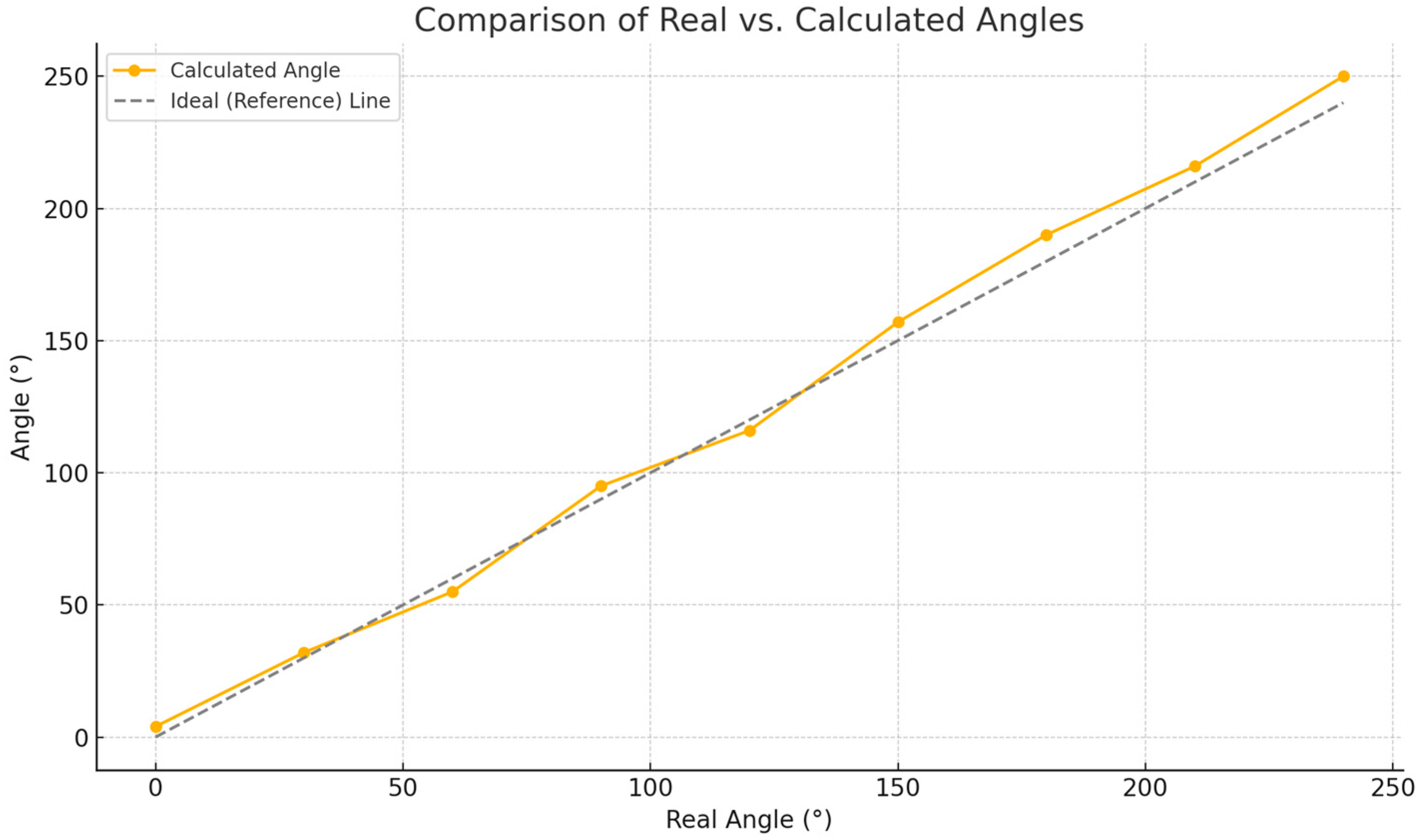
Figure 1. Microphone Placement, in mm, on the UAV Platform.
Acoustics 07 00048 g001
Figure 2. Microphone Placement on the UAV Platform [24].
Acoustics 07 00048 g002
Figure 3. Logical scheme of the system integrated on UAV platform.
Acoustics 07 00048 g003
Figure 4. Logical structure of artificial intelligence (AI) training.
Acoustics 07 00048 g004
Figure 5. Ruris Expert 351 Chainsaw Spectrogram.
Acoustics 07 00048 g005
Figure 6. Husqvarna 135 Mark II Chainsaw Spectrogram.
Acoustics 07 00048 g006
Figure 7. Power Drill Spectrogram.
Acoustics 07 00048 g007
Figure 8. Radio spectrogram.
Acoustics 07 00048 g008
Figure 9. Human Speech Spectrogram.
Acoustics 07 00048 g009
Figure 10. UAV platform stand in anechoic chamber.
Acoustics 07 00048 g010
Figure 11. Testing configuration of Probe 1 and Probe 2.
Acoustics 07 00048 g011
Figure 12. Probe 1 Spectrogram.
Acoustics 07 00048 g012
Figure 13. Calibrated Probe 1 Spectrogram.
Acoustics 07 00048 g013
Figure 14. Sound Pressure Level Distribution and Temporal Evolution for Probe 1.
Acoustics 07 00048 g014
Figure 15. Probe 2 Spectrogram.
Acoustics 07 00048 g015
Figure 16. Calibrated Probe 2 Spectrogram.
Acoustics 07 00048 g016
Figure 17. Sound Pressure Level Distribution and Temporal Evolution for Probe 2.
Acoustics 07 00048 g017
Figure 18. Ground testing configuration of AI system [24].
Acoustics 07 00048 g018
Figure 19. Model Confidence per Audio Test Mic. 1.
Acoustics 07 00048 g019
Figure 20. Model Confidence per Audio Test Mic. 2.
Acoustics 07 00048 g020
Figure 21. Model Confidence per Audio Test Mic. 3.
Acoustics 07 00048 g021
Figure 22. Model Confidence per Audio Test Mic. 4.
Acoustics 07 00048 g022
Figure 23. Microphone array configuration on a UAV platform for source localization.
Acoustics 07 00048 g023
Figure 24. In-flight experimental setup for acoustic source localization using a UAV-mounted microphone array and a ground-based sound source.
Acoustics 07 00048 g024
Figure 25. Comparison between real and calculated angles during static localization tests.
Acoustics 07 00048 g025
Table 1. Real vs. calculated angles during sound localization tests.
Test No.Real Angle [°]Resulted Angle [°]
100
22527
34548.6
46064.8
57075.6
69097.2
7135145.8
8180194.4
9200216
10240260
Disclaimer/Publisher’s Note: The statements, opinions and data contained in all publications are solely those of the individual author(s) and contributor(s) and not of MDPI and/or the editor(s). MDPI and/or the editor(s) disclaim responsibility for any injury to people or property resulting from any ideas, methods, instructions or products referred to in the content.

