Article

Experimental Investigation of Bulk Elastic Wave Propagation in the Volume of Metamaterials

by
Aleksandr Korobov
1,
Natalia Shirgina
1,
Aleksey Kokshaiskii
1,
Natalia Odina
1 and
Aleksandr Volodarskii
2,*
1
Faculty of Physics, Moscow State University, Moscow 119991, Russia
2
Emanuel Institute of Biochemical Physics RAS, Moscow 119334, Russia
*
Author to whom correspondence should be addressed.
Acoustics 2025, 7(3), 40; https://doi.org/10.3390/acoustics7030040
Submission received: 22 March 2025 / Revised: 24 May 2025 / Accepted: 13 June 2025 / Published: 26 June 2025

Abstract

This paper presents the results of experimental studies on the propagation of longitudinal and transverse ultrasonic waves through a metamaterial—a composite material based on polymer matrix with periodically arranged cylindrical elements. Such structures are known as phononic crystals. Amplitude–frequency characteristics were measured for phononic crystals with air and metal cylindrical elements, for both longitudinal waves (in the frequency range from 1.5 to 3 MHz) and transverse waves (in the range from 0.2 to 1.2 MHz). A twofold decrease in the amplitude of the transmitted longitudinal ultrasonic wave was experimentally demonstrated in the passband centered at 1.87 MHz during rotation of the phononic crystal. It was also found that the polarization angle of the transverse ultrasonic wave influences the localization of band gaps and passbands. Band gaps, characterized by amplitude minima near 240 kHz, 290 kHz, and 830 kHz and observed for waves polarized parallel to the crystal axis, are replaced by passbands when the wave is polarized perpendicularly. These results suggest the potential for developing analog ultrasonic frequency filters tunable by the angle of rotation.

1. Introduction

A metamaterial is a composite material, the properties of which are determined by its artificially created periodic structure rather than by the properties of its constituent elements. The artificial periodic structure of the material modifies its physical properties, which allows metamaterials to exhibit a negative refractive index and backward wave propagation [1] and to have a zero refractive index [2], band gaps [3], and superabsorption [4]. Interest in metamaterials arose in the mid-20th century with the work of Veselago, in which a material with a negative refractive index was theoretically described [5]. Much later (thirty years later), such materials were produced [6]. Today, the structure and properties of metamaterials [7,8] and phononic crystals [9,10,11,12,13,14,15,16,17,18,19,20,21,22,23,24,25,26] as a subclass of metamaterials attract significant interest.
Phononic crystals are an artificial periodic structure with the size of each unit cell equal to the radiation length. The structure of a crystal determines its properties and applications. Huang et al. [10] proposed a crystal with a lattice resembling a graphene allotrope, which has negative refraction of plane waves in the frequency range from 0 to 50 kHz. Laude [11] summarized various designs of waveguides based on 2D phononic crystals. Phononic crystal waveguides replace the cladding of classical homogeneous waveguides by a crystal possessing a complete phononic band gap. These phononic crystals waveguides can provide waveguides with backscattering immunity, and are often considered as a tunable manipulation of acoustic or elastic waves. Another possible application of phononic crystals is energy harvesting [12,13]. Phononic crystals create band gaps in certain frequency ranges and prevent acoustic waves from passing through the material [12]. Using an energy conversion system, the captured wave energy can be harvested in the form of strain energy. In this work, designs of phononic crystals for filtering ultrasonic signals are proposed. It should be noted that the frequency band gaps and zone structure in total are the main characteristics of phononic crystals.
Kushwaha et al. performed calculations of the zone structure in periodic elastic composites [14]. For transverse elastic waves polarized parallel to the axis of inclusions in the matrix, a “phonon” band gap was obtained, which coincides with the Brillouin zone. In [15], the authors calculated the zone structure of elastic waves propagating in two-dimensional periodic liquids or solid systems, respectively. In liquids, zones are formed simply, in contrast to the case of solids, where a large difference in density values is required. Vasseur et al. [16] studied, theoretically and experimentally, the zone structure of a two-dimensional phononic crystal consisting of steel cylinders 4 mm in diameter placed in an epoxy matrix. The measurements and numerical calculations proved the existence of two absolute band gaps that do not depend on the direction of propagation of acoustic waves. Li et al. [17] proposed a method for creating phononic crystals with large band gaps widths. In the work, it was shown by numerical simulation that the gap between two band gaps in a planar mode can be formed by using a certain number of solid or hollow round rods embedded in the matrix material. Krushynska et al. [18] theoretically analyzed a solid metamaterial with so-called quasi-resonant Bragg gaps. It was shown that the latter were achieved by overlapping the Bragg band gap with local resonant modes of the metamaterial. Wang et al. [19] supposed the equations and dispersion relations of bending waves propagating in piezoelectric phononic crystal using Mindlin’s theory combined with the plane wave expansion method. It is found that the inclusion shape significantly affects the band gap in the mid- and high-frequency ranges. The thickness affects the band gap differently than in two-dimensional models, and the cuts significantly affect the band gap. Jing et al. [20] reported that two-dimensional hierarchical crystals with local band gaps can be applied for noise suppression. Thus, it can be concluded that the zone structure of phonon crystals determines their practical application. Here, we propose 3D phononic crystals with specific zone structures in the frequency range from 0.2 to 3 MHz. The crystals are formed from acrylonitrile-butadiene-styrene (ABS) with metal and air periodical cylindrical inclusions. Similar periodical structures were investigated by Mukhin et al. [21], Sekar et al. [22], Khelif et al. [23], Hladky-Hennion et al. [24], and Jiang et al. [25]; however, they used air, metals, liquids, or epoxy as matrix materials. Ibarias et al. [26] researched acoustic properties in the frequency range 0~2 kHz of similar structures, which were made from ABS. Experimental investigation of ultrasound waves propagation in phononic crystals based on ABS are described for the first time in this work. Furthermore, the frequency range from 0.2 to 3 MHz chosen in this work provide the possibility to assess both longitudinal and transverse wave propagation in various directions of crystals.
Thus, the work considers the passage of longitudinal and transverse ultrasonic waves through a phononic crystal made of ABS depending on the inclusion materials, the rotation of the phononic crystal, and the rotation of the polarization plane relative to the axis of the phononic crystal.

2. Materials and Methods

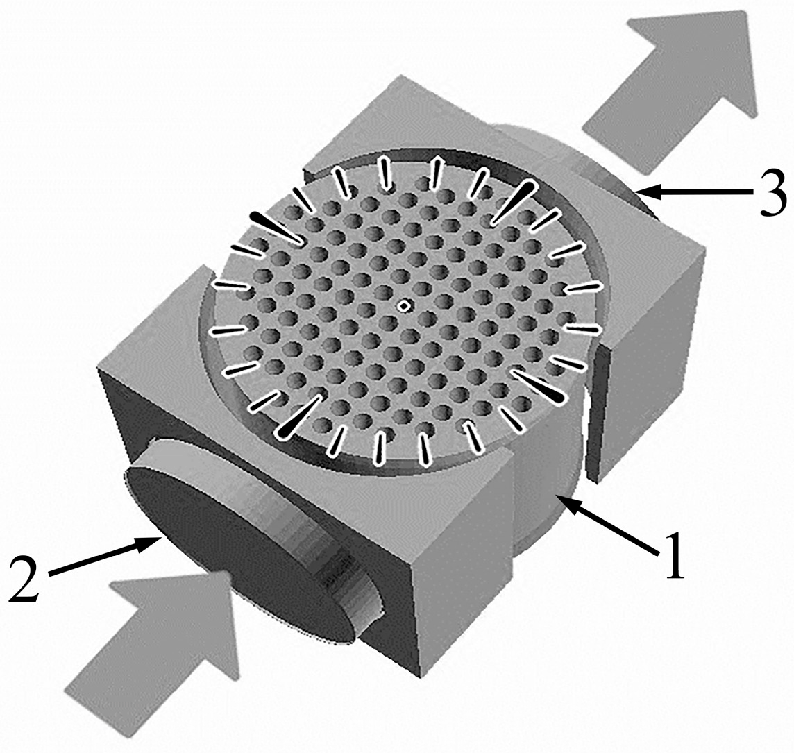
2.1. Design of the Phononic Crystal

The phononic crystal was made by 3D printing on a 3DQ Mini printer using FDM technology with a printing temperature of 160 °C from polyacrylonitrile-butadiene-styrene (ABS) in the form of a cylinder with a diameter of 33.7 mm and a height of 34 mm. The thread sizes were 0.5 mm in the transverse plane and 0.1 mm in the plane of the cylinder axis. One hundred twenty-one cylindrical holes with a diameter of 1.8 mm and a period of 3 mm were located in parallel to the axis of the cylinder. The design of the experimental cell (Figure 1) provided the ability to rotate the phononic crystal by 360° around its own axis, which allowed us to study the propagation of elastic waves through a structure with a variable periodicity. The structural elements were joined using an acoustic grease composed of silicone oil and vacuum grease. The gap between the elements was approximately 0.1 mm, which is 5 to 10 times smaller than the wavelength and therefore can be neglected.
The studies of the propagation of volume elastic waves were carried out on two phononic crystals: crystal No. 1 with air filling of cylindrical cavities and crystal No. 2 with filling of cylindrical cavities with metal rods. The difference between the acoustic impedance of the matrix material and the filling material of the phononic crystal affects the amplitude-frequency characteristic (AFC) of the crystal. The values of density, velocities of longitudinal and transverse elastic waves, and acoustic impedances of the materials used in the phononic crystals are presented in Table 1.

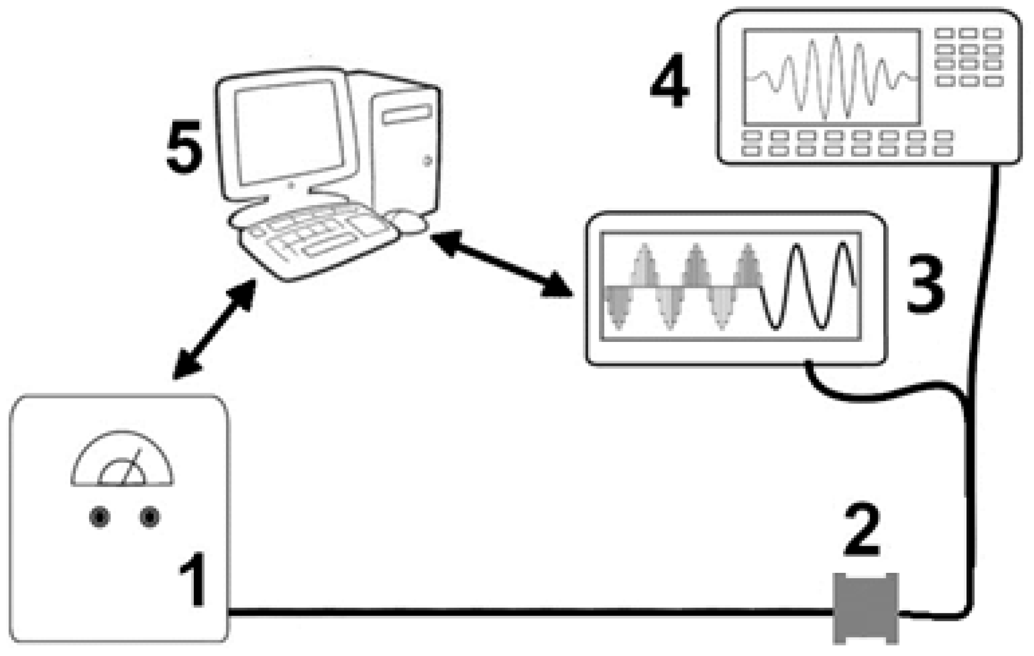
2.2. Experimental Setup

The study of the propagation of ultrasonic waves along the phononic crystal was carried out using an experimental setup (Figure 2). The setup included a generator of short high-voltage pulses (1), an experimental cell with a phononic crystal (2), a high-speed analog-to-digital converter (ADC) (3), an oscilloscope (4), and a control computer (PC) (5), with the help of which the operation of all elements was synchronized.
Excitation and reception of longitudinal and transverse elastic waves were performed using piezoceramic transducers with a diameter of 28 mm with a resonance frequency of ~1 MHz for longitudinal waves and ~0.34 MHz for transverse waves, located at the ends of the experimental cell (Figure 1). The range of frequencies used for longitudinal waves was from 1.5 to 3 MHz, and for transverse waves from 0.2 to 1.2 MHz. In the range under consideration, the length of a longitudinal wave in the polymer was from 0.56 to 1.13 mm, and a transverse wave from 0.69 to 4.15 mm, which is comparable with the periodicity of the phononic crystal structure.

2.3. Statistics and Error Estimation
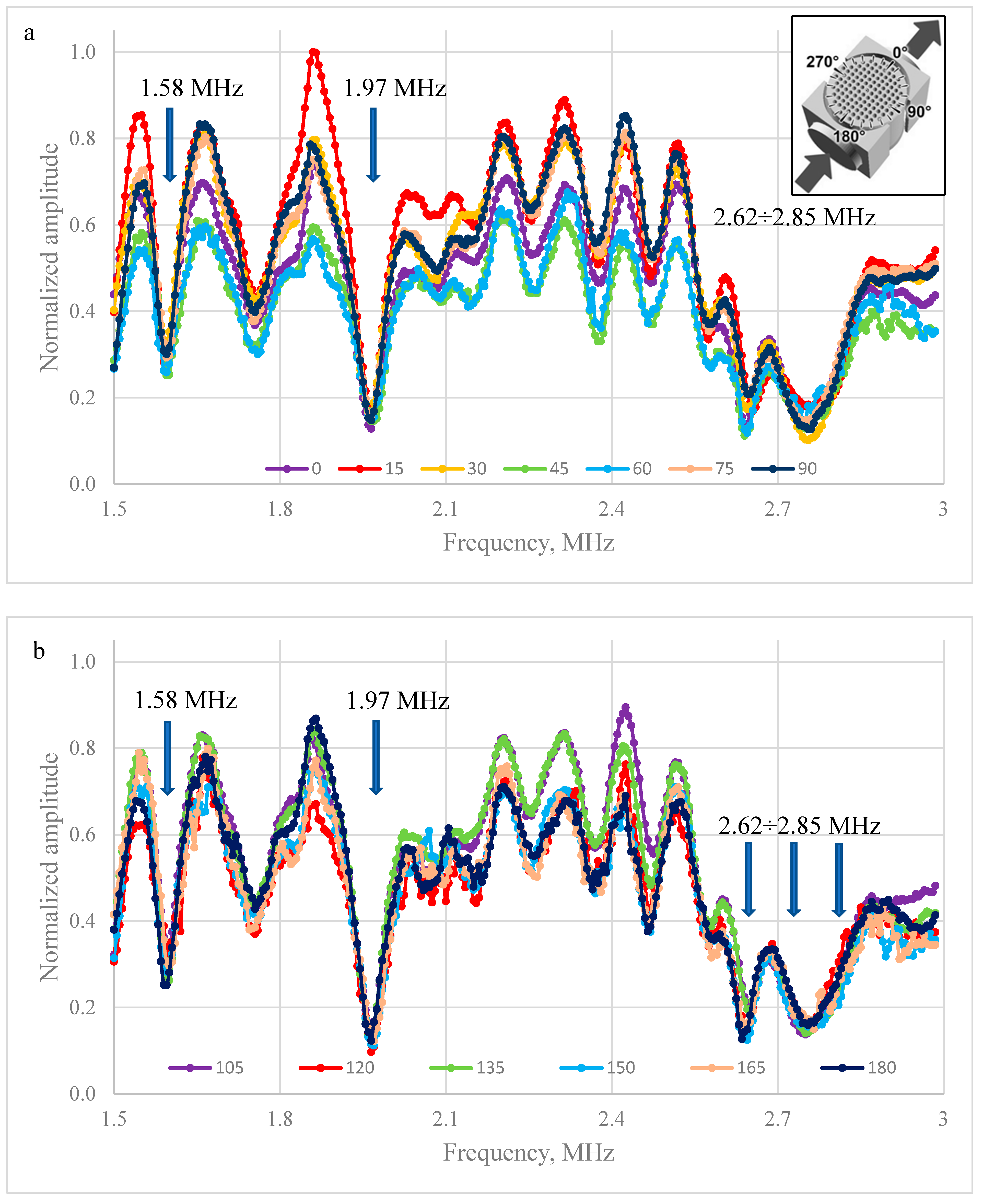
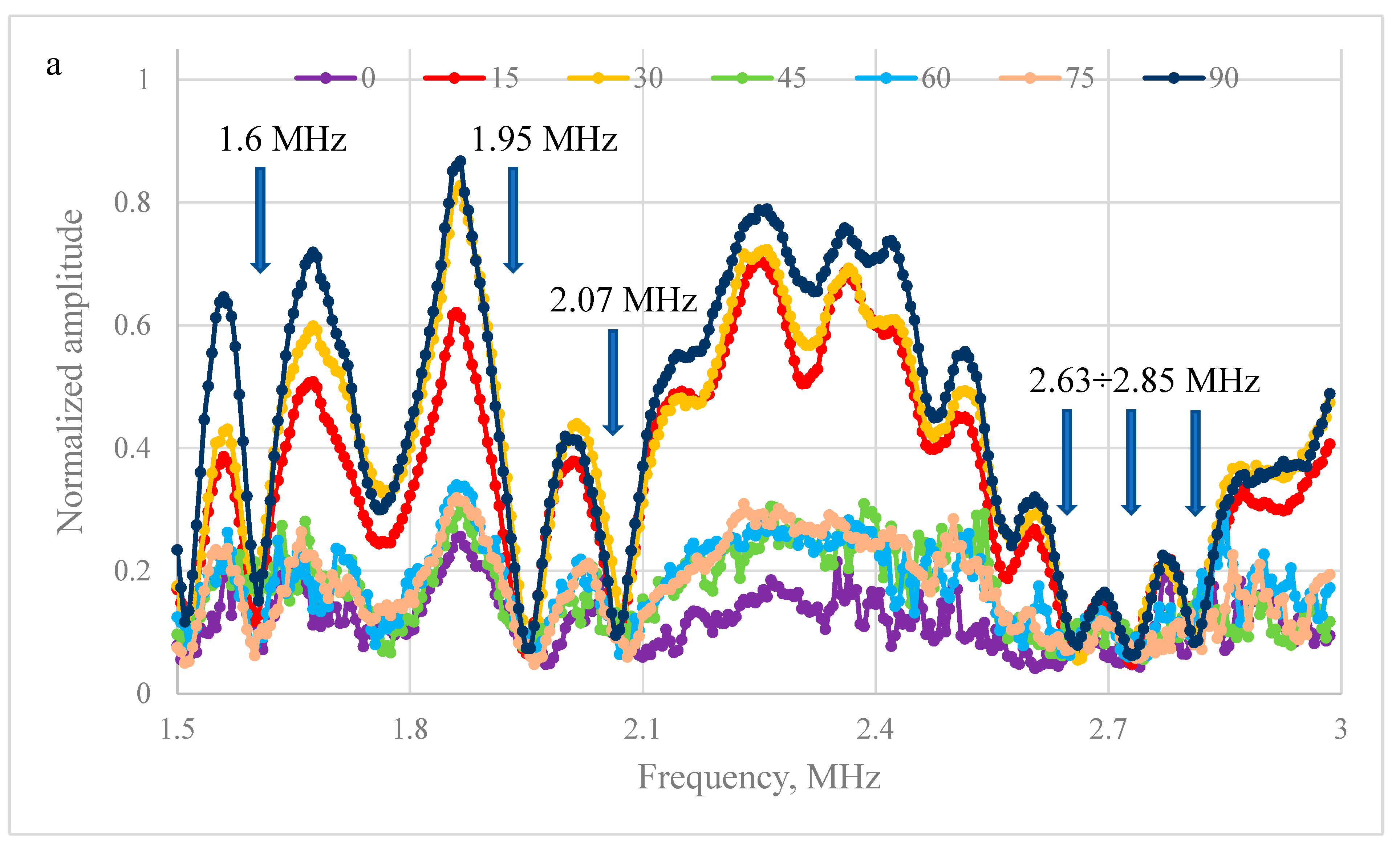
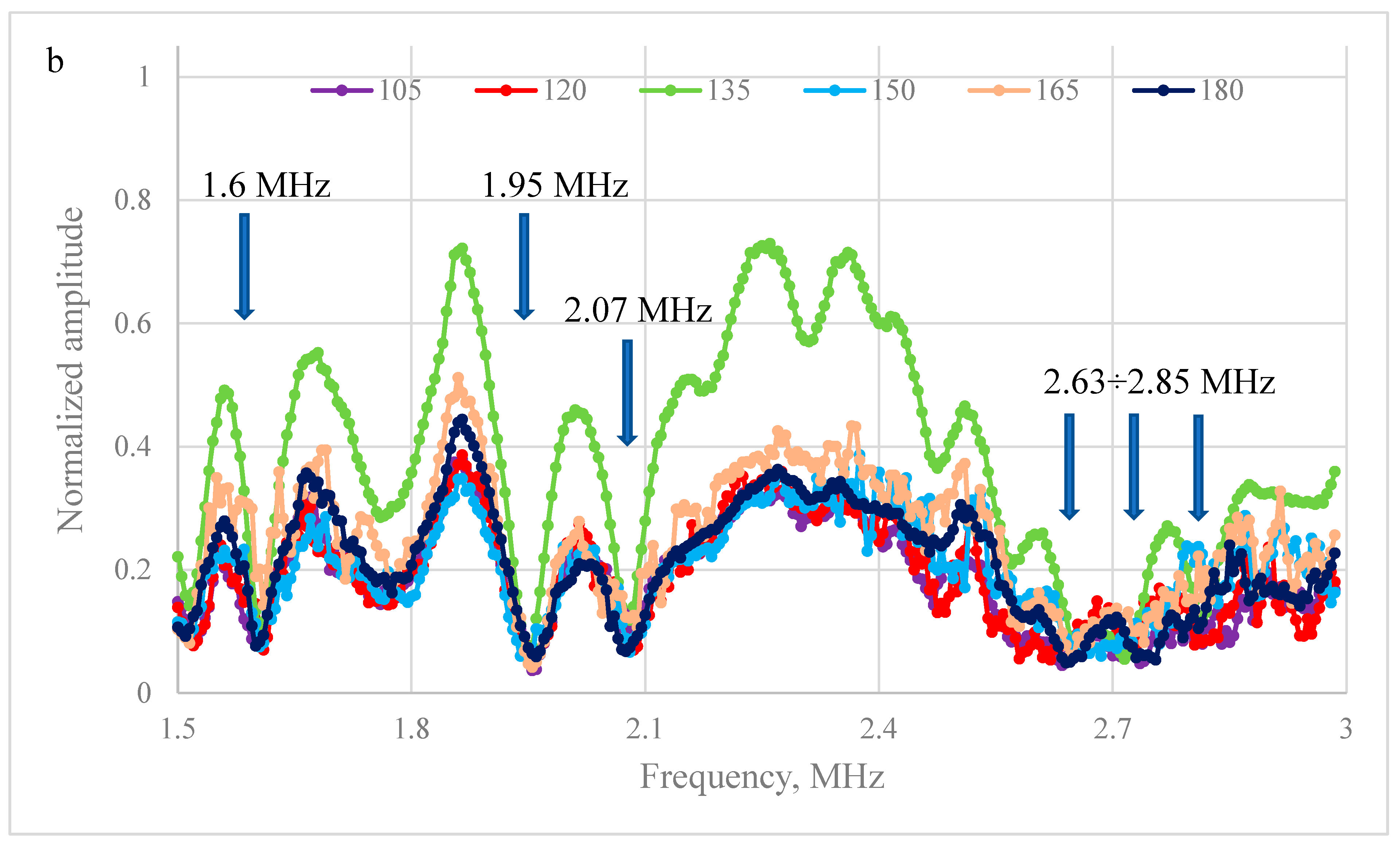
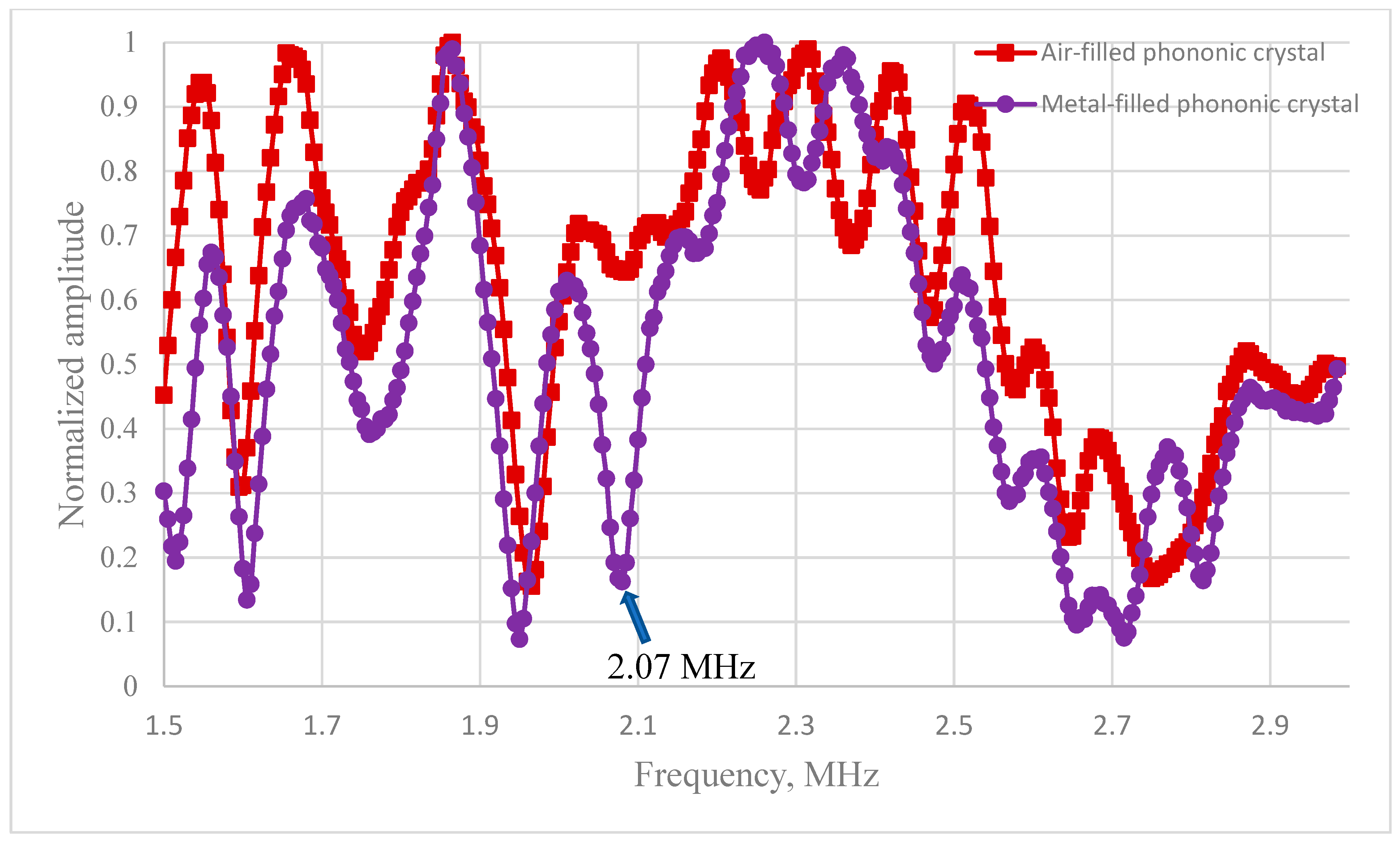
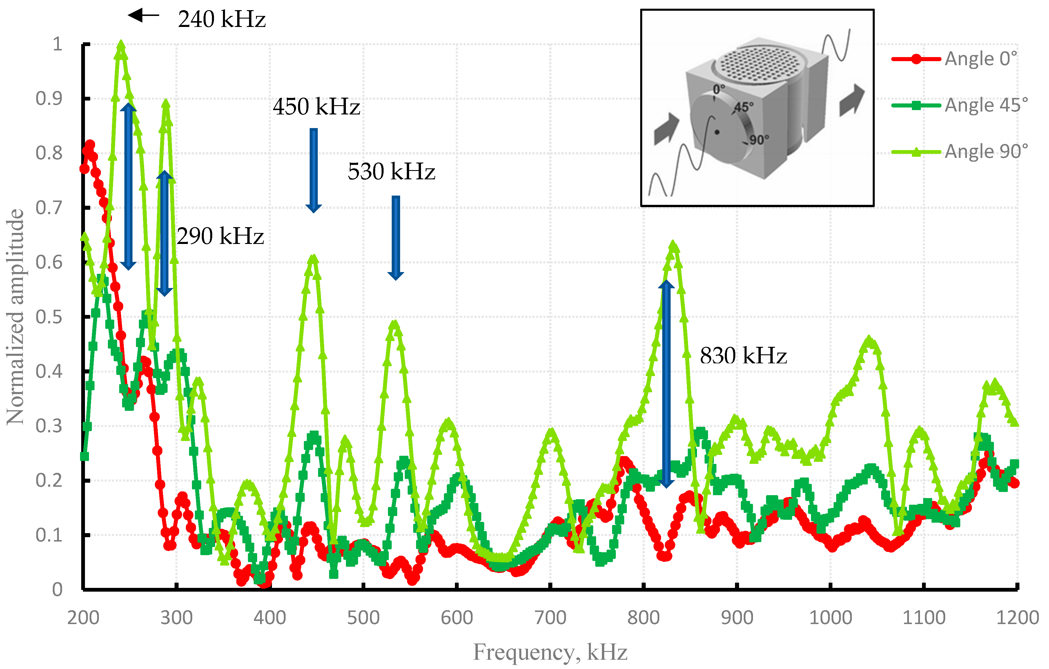
The measurements of amplitude-frequency response of phononic crystals were obtained with a crystal rotation step of 3°, and the angular positioning error was 0.5°. The error of the signal frequency and amplitude values is set by experimental equipment and an analog-to-digital converter. The frequency measurement error was approximately 1%, while the amplitude measurement error was around 3%.

3. Results

The results of experimental studies of elastic wave propagation are presented in the form of frequency response diagrams for phononic crystals No. 1, 2, normalized to the amplitudes of signals that pass through the ABS volume without a periodic structure. Normalization allows elimination of the influence of the converter’s own amplitude-frequency dependence.
Figure 3a,b shows the frequency response for an air-filled phononic crystal for crystal rotation angles in the range from 0° to 90° (Figure 3a) and from 105° to 180° (Figure 3b) with a step of 15°. The longitudinal wave data were obtained with a phonon crystal rotation step of 3 degrees. Full data for all samples are presented in the Supplementary Materials. The maxima associated with resonances of the internal periodic structure of the phononic crystal are observed. The forbidden frequencies and passband frequencies coincide for all sample rotation angles. The amplitudes of the received signals vary, and it is impossible to single out any one direction in which the amplitude is higher over the entire frequency range. For the rotations of 15° and 90° (Figure 3a), and 105°, 135°, and 180° (Figure 3b), the highest values of the received signal are observed in different areas. Thus, changing the rotation angle of the sample relative to the propagation of the longitudinal wave makes it possible to decrease the magnitude of the received signal by half without changing the frequency. The lowest values of the amplitudes of the transmitted signals are observed when the phonon crystal is rotated by 45°. Significant absorption of longitudinal ultrasonic waves is observed near frequencies of 1.58 MHz and 1.97 MHz and in the band from 2.62 to 2.85 MHz. The position of the band gaps remains largely unchanged when the crystal is rotated relative to the direction of wave propagation. In comparison, Jiang et al. [25] reported that rotation of the phononic crystal by 15°, 30°, and 45° caused a shift only in the numerically obtained band gaps. The authors attribute this to Bragg’s law.
Figure 4 shows the frequency response of a phononic crystal with a metal filling; however, the frequencies of the stop bands are different and the amplitude minima corresponding to them are localized at frequencies of 1.6 MHz, 1.95 MHz, and 2.07 MHz and in the region of 2.63~2.85 MHz. It was found that when turning by 15°, 30°, 90°, and 135° in the frequency range of 1.5~3 MHz, the amplitude of the transmitted signal increases compared to other directions of propagation of the ultrasonic wave.
Comparing the frequency response of phononic crystals with various fillings of cylindrical holes, we can note the occurrence of a band gap with a minimum at a frequency of 2.07 MHz in a crystal with a metal filling (Figure 5). The minimum amplitude is associated with the fact that at this frequency, 4 Rayleigh wavelengths fit along the surface of metal cylinders, the speed of which in steel is about 2970 m/s, and the wavelength is 1.43 mm; this is in contrast to longitudinal waves in a polymer, where the speed is about 1690 m/s and the wavelength is 0.82 mm. This can lead to the resonance of the rods and the formation of interference minima during re-radiation into the polymer volume.
A phononic crystal with metallic filling of cavities is of particular interest since transverse waves can propagate in its volume. Figure 6 shows the frequency response for waves with different polarizations. It is shown that for transverse waves with a polarization vector parallel to the metallic cylinders filling the sample, minimum values of the amplitudes of transmitted signals with local maxima not exceeding 30% are observed practically over the entire frequency range (0.3~1.2 MHz). The maxima of the amplitude of the transmitted wave are observed for all polarization directions at frequencies of 450 kHz and 530 kHz. At frequencies of 240 kHz, 290 kHz, and 830 kHz, the maxima of the wave polarized perpendicularly coincide with the minima for waves with other polarization directions.

4. Discussion

In this work, the propagation of ultrasonic waves through two phononic crystals with different inclusion materials filling the periodic cavities was investigated. The obtained amplitude-frequency dependences for longitudinal waves in the frequency range from 1.5 to 3 MHz with the crystal rotated around its own axis from 0° to 180° showed the presence of 3 non-transmission bands in this range for the air-filled phononic crystal (with the amplitude minima localized near 1.58 MHz and 1.97 MHz and in the range from 2.62 to 2.85 MHz) and 4 non-transmission bands for the metal-filled phononic crystal (with the amplitude minima localized near 1.6 MHz, 1.95 MHz, and 2.07 MHz and in the range from 2.63 to 2.85 MHz). The transmission depends on the rotation angle of the phononic crystal, since the propagation of waves can be affected by the direction of the laying of the threads during FDM printing of the sample. The minimum near the frequency of 2.07 MHz was associated with the resonance of Rayleigh waves on the surface of the metal rods. Other minima were associated with the geometry and periodic structure of the phononic crystal.
The observed pattern of passbands and band gaps for ultrasonic longitudinal waves suggests that phononic crystals of this design can function as analog bandpass filters, which can be tuned by altering the filling material.
The passage of transverse waves in the frequency range from 200 kHz to 1200 kHz was investigated for the phononic crystal with a metal filling; amplitude-frequency dependences were obtained for the waves polarized in three planes (at angles of 0°, 45°, and 90° to the axis of the phononic crystal). For the wave polarized perpendicularly, a strongly jagged frequency response of the phononic crystal was observed. For the waves with other polarization directions, a minimum value of the amplitudes of the transmitted signals was noted in the range above 300 kHz.
The obtained results showed the possibility of using the phononic crystal of the considered design as an analog bandpass filter, tuned by rotating the crystal axis relative to the plane of polarization of the incident wave.
The presence of local maxima of the received amplitude of the transmitted acoustic wave, which did not coincide for different polarization directions, allowed us to assume that the applied design of the phononic crystal could act as not only a bandpass, but also a polarization filter for transverse waves.

5. Conclusions

In this work, the propagation of longitudinal and transverse ultrasonic waves through phononic crystals made of ABS with air and metal filling was experimentally investigated. The amplitude-frequency characteristics were obtained for longitudinal (in the frequency range from 1.5 to 3 MHz) and transverse waves (in the frequency range from 0.2 to 1.2 MHz) transmitted through the phononic crystals. A two-fold decrease in amplitude was experimentally obtained for a longitudinal ultrasonic wave in the passband centered at a frequency of 1.87 MHz during the rotation of the phononic crystal about its axis. It was shown that the polarization angle of the transverse ultrasonic wave affected the localization of the band gaps and passbands. The band gaps with amplitude minima localized at 240 kHz, 290 kHz, and 830 kHz observed for a wave polarized parallel to the crystal axis were replaced by passbands for a wave polarized perpendicularly.

Supplementary Materials

The following supporting information can be downloaded at: https://www.mdpi.com/article/10.3390/acoustics7030040/s1, Figure S1: Series of frequency response for phononic crystal No. 1 at angles of 0°~15° of incidence of a longitudinal elastic wave relative to the axis of symmetry of the hole arrangement; Figure S2: Series of frequency response for phononic crystal No. 1 at angles of 18°~30° of incidence of a longitudinal elastic wave relative to the axis of symmetry of the hole arrangement; Figure S3: Series of frequency response for phononic crystal No. 1 at angles of 33°~45° of incidence of a longitudinal elastic wave relative to the axis of symmetry of the hole arrangement; Figure S4: Series of frequency response for phononic crystal No. 1 at angles of 48°~60° of incidence of a longitudinal elastic wave relative to the axis of symmetry of the hole arrangement; Figure S5: Series of frequency response for phononic crystal No. 1 at angles of 63°~75° of incidence of a longitudinal elastic wave relative to the axis of symmetry of the hole arrangement; Figure S6: Series of frequency response for phononic crystal No. 1 at angles of 78°~90° of incidence of a longitudinal elastic wave relative to the axis of symmetry of the hole arrangement; Figure S7: Series of frequency response for phononic crystal No. 1 at angles of 93°~105° of incidence of a longitudinal elastic wave relative to the axis of symmetry of the hole arrangement; Figure S8: Series of frequency response for phononic crystal No. 1 at angles of 108°~120° of incidence of a longitudinal elastic wave relative to the axis of symmetry of the hole arrangement; Figure S9: Series of frequency response for phononic crystal No. 1 at angles of 123°~135° of incidence of a longitudinal elastic wave relative to the axis of symmetry of the hole arrangement; Figure S10: Series of frequency response for phononic crystal No. 1 at angles of 138°~150° of incidence of a longitudinal elastic wave relative to the axis of symmetry of the hole arrangement; Figure S11: Series of frequency response for phononic crystal No. 1 at angles of 153°~165° of incidence of a longitudinal elastic wave relative to the axis of symmetry of the hole arrangement; Figure S12: Series of frequency response for phononic crystal No. 1 at angles of 168°~180° of incidence of a longitudinal elastic wave relative to the axis of symmetry of the hole arrangement; Figure S13: Series of frequency responses for phononic crystal No. 2 at angles of 0°~15° of incidence of a longitudinal elastic wave relative to the axis of symmetry of the hole arrangement; Figure S14: Series of frequency responses for phononic crystal No. 2 at angles of 18°~30° of incidence of a longitudinal elastic wave relative to the axis of symmetry of the hole arrangement; Figure S15: Series of frequency responses for phononic crystal No. 2 at angles of 33°~45° of incidence of a longitudinal elastic wave relative to the axis of symmetry of the hole arrangement; Figure S16: Series of frequency responses for phononic crystal No. 2 at angles of 48°~60° of incidence of a longitudinal elastic wave relative to the axis of symmetry of the hole arrangement; Figure S17: Series of frequency responses for phononic crystal No. 2 at angles of 63°~75° of incidence of a longitudinal elastic wave relative to the axis of symmetry of the hole arrangement; Figure S18: Series of frequency responses for phononic crystal No. 2 at angles of 78°~90° of incidence of a longitudinal elastic wave relative to the axis of symmetry of the hole arrangement; Figure S19: Series of frequency responses for phononic crystal No. 2 at angles of 93°~105° of incidence of a longitudinal elastic wave relative to the axis of symmetry of the hole arrangement; Figure S20: Series of frequency responses for phononic crystal No. 2 at angles of 108°~120° of incidence of a longitudinal elastic wave relative to the axis of symmetry of the hole arrangement; Figure S21: Series of frequency responses for phononic crystal No. 2 at angles of 123°~135° of incidence of a longitudinal elastic wave relative to the axis of symmetry of the hole arrangement; Figure S22: Series of frequency responses for phononic crystal No. 2 at angles of 138°~150° of incidence of a longitudinal elastic wave relative to the axis of symmetry of the hole arrangement; Figure S23: Series of frequency responses for phononic crystal No. 2 at angles of 153°~165° of incidence of a longitudinal elastic wave relative to the axis of symmetry of the hole arrangement; Figure S24: Series of frequency responses for phononic crystal No. 2 at angles of 168°~180° of incidence of a longitudinal elastic wave relative to the axis of symmetry of the hole arrangement; Figure S25: Normalized frequency responses of phononic crystal No. 2 for different orientations of the polarization vector of the transverse elastic wave.

Author Contributions

Conceptualization, A.K. (Aleksandr Korobov) and N.S.; methodology, A.K. (Aleksey Kokshaiskii); validation, A.K. (Aleksey Kokshaiskii), N.O. and A.V.; investigation, A.K. (Aleksey Kokshaiskii) and A.V.; resources, A.K. (Aleksey Kokshaiskii); data curation A.K. (Aleksey Kokshaiskii) and A.V.; writing—original draft preparation, N.S.; writing—review and editing, A.V.; visualization, A.V.; supervision, A.K. (Aleksandr Korobov) and N.O.; project administration, N.O. All authors have read and agreed to the published version of the manuscript.

Funding

The studies of elastic characteristics were carried out with the support of a grant from the Russian Science Foundation (project No. 19-12-00098).

Data Availability Statement

Data are contained within the article or Supplementary Material.

Conflicts of Interest

The authors declare no conflicts of interest.

Abbreviations

The following abbreviations are used in this manuscript:
ABSPolyacrylonitrile-butadiene-styrene
ADC Analog-to-digital converter
AFCAmplitude Frequency Characteristic
PCPersonal computer
FDMFused deposition modeling

References

  1. Pendry, J.B. Negative refraction makes a perfect lens. Phys. Rev. Lett. 2000, 85, 3966–3969. [Google Scholar] [CrossRef] [PubMed]
  2. Silveirinha, M.; Engheta, N. Tunneling of Electromagnetic Energy through Subwavelength Channels and Bends using ε-Near-Zero Materials. Phys. Rev. Lett. 2006, 97, 157403. [Google Scholar] [CrossRef]
  3. Erofeev, V.I.; Pavlov, I.S. Mechanics and acoustics of metamaterials: Mathematical modeling, experimental research, prospects for application in mechanical engineering. Probl. Strength Plast. 2021, 83, 391–414. [Google Scholar] [CrossRef]
  4. Landy, N.I.; Sajuyigbe, S.; Mock, J.J.; Smith, D.R.; Padilla, W.J. Perfect metamaterial absorber. Phys. Rev. Lett. 2008, 100, 207402. [Google Scholar] [CrossRef] [PubMed]
  5. Veselago, V.G. The electrodynamics of substances with simultaneously negative values of ε and μ. Sov. Phys. Uspekhi 1968, 10, 509–514. [Google Scholar] [CrossRef]
  6. Smith, D.R.; Padilla, W.J.; Vier, D.C.; Nemat-Nasser, S.C.; Schultz, S. Composite Medium with Simultaneously Negative Permeability and Permittivity. Phys. Rev. Lett. 2000, 84, 4184–4187. [Google Scholar] [CrossRef]
  7. Vendik, I.B.; Vendik, O.G. Metamaterials and their application in microwaves: A review. Tech. Phys. 2013, 58, 1–24. [Google Scholar] [CrossRef]
  8. Veselago, V.G. Waves in metamaterials: Their role in modern physics. Phys.-Uspekhi 2011, 54, 1161–1165. [Google Scholar] [CrossRef]
  9. Muhammad; Lim, C.W. From photonic crystals to seismic metamaterials: A review via phononic crystals and acoustic metamaterials. Arch. Comput. Methods Eng. 2022, 29, 1137–1198. [Google Scholar] [CrossRef]
  10. Huang, H.; Huo, S.; Chen, J. Subwavelength elastic topological negative refraction in ternary locally resonant phononic crystals. Intern. J. Mech. Sc. 2021, 198, 106391. [Google Scholar] [CrossRef]
  11. Laude, V. Principles and properties of phononic crystal waveguides. APL Mater. 2021, 9, 080701. [Google Scholar] [CrossRef]
  12. Akbari-Farahani, F.; Ebrahimi-Nejad, S. From defect mode to topological metamaterials: A state-of-the-art review of phononic crystals & acoustic metamaterials for energy harvesting. Sens. Act. A Phys. 2024, 365, 114871. [Google Scholar] [CrossRef]
  13. Dhillon, J.; Walker, E.; Krokhin, A.; Neogi, A. Energy trapping in a phononic crystal cavity enhanced by nonreciprocal acoustic wave transmission. App. Acoust. 2023, 203, 109192. [Google Scholar] [CrossRef]
  14. Kushwaha, M.S.; Halevi, P.; Dobrzynski, L.; Djafari-Rouhani, B. Acoustic Band-Structure of Periodic Elastic Composites. Phys. Rev. Lett. 1993, 71, 2022–2025. [Google Scholar] [CrossRef] [PubMed]
  15. Sigalas, M.; Economou, E.N. Band structure of elastic waves in two dimensional systems. Solid State Commun. 1993, 86, 141–143. [Google Scholar] [CrossRef]
  16. Vasseur, J.O.; Deymier, P.A.; Chenni, B.; Djafari-Rouhani, B.; Dobrzynski, L.; Prevost, D. Experimental and Theoretical Evidence for the Existence of Absolute Acoustic Band Gaps in Two-Dimensional Solid Phononic Crystals. Phys. Rev. Lett. 2001, 86, 3012–3015. [Google Scholar] [CrossRef]
  17. Li, Y.F.; Meng, F.; Li, S.; Jia, B.; Zhou, S.; Huang, X. Designing broad phononic band gaps for in-plane modes. Phys. Lett. A 2018, 382, 679–684. [Google Scholar] [CrossRef]
  18. Krushynska, A.O.; Miniaci, M.; Bosia, F.; Pugno, N.M. Coupling local resonance with Bragg band gaps in single-phase mechanical metamaterials. Extrem. Mech. Lett. 2017, 12, 30–36. [Google Scholar] [CrossRef]
  19. Wang, Z.; Zhou, C.; Dong, Y.; Zhu, S.; Pei, W.; Weng, J. Research on bending vibration characteristics of phononic crystal plates based on Mindlin’s piezoelectric plate theory. Smart Mater. Struct. 2023, 32, 105012. [Google Scholar] [CrossRef]
  20. Jing, J.; Sun, P.; Wu, Z.; Li, F. Investigation on enhanced band-gap properties of 2D hierarchical phononic crystals. Mech. Syst. Sig. Proc. 2025, 223, 111827. [Google Scholar] [CrossRef]
  21. Mukhin, N.; Kutia, M.; Aman, A.; Steinmann, U.; Lucklum, R. Two-dimensional phononic crystal based sensor for characterization of mixtures and heterogeneous liquids. Sensors 2022, 22, 2816. [Google Scholar] [CrossRef] [PubMed]
  22. Sekar, V.; Cantwell, W.J.; Liao, K.; Berton, B.; Jacquart, P.M.; Abu Al-Rub, R.K. Additively manufactured metamaterials for acoustic absorption: A review. Virtual Phys. Prototyp. 2024, 19, e2435562. [Google Scholar] [CrossRef]
  23. Khelif, A.; Hsiao, F.-L.; Choujaa, A.; Benchabane, S.; Laude, V. Octave omnidirectional band gap in a three-dimensional phononic crystal. IEEE Trans. Ultrason. Ferroelec. Freq. Control 2010, 57, 1621–1625. [Google Scholar] [CrossRef]
  24. Hladky-Hennion, A.-C.; Vasseur, J.O.; Haw, G.; Croënne, C.; Haumesser, L.; Norris, A.N. Negative refraction of acoustic waves using a foam-like metallic structure. Appl. Phys. Lett. 2013, 102, 144103. [Google Scholar] [CrossRef]
  25. Jiang, G.; Liu, Y.; Wu, Y.; Xu, W.; Kong, Q.; Zhang, C. Transmission and radiation of acoustic oblique incident through tube arrays based on phononic crystals theory. Appl. Acous. 2017, 116, 117–126. [Google Scholar] [CrossRef]
  26. Ibarias, M.; Sánchez-Dehesa, J.; Krokhin, A. Phononic supercrystal as a highly absorbing metamaterial. Phys. Rev. Res. 2024, 6, L042005. [Google Scholar] [CrossRef]
Figure 1. Schematic representation of the experimental cell: 1—phononic crystal made of ABS with a periodic lattice of cylindrical holes, 2—piezoelectric ultrasound emitter, 3—ultrasound receiver.
Acoustics 07 00040 g001
Figure 2. Experimental setup scheme: 1—generator, 2—experimental cell, 3—ADC, 4—oscilloscope, 5—PC.
Acoustics 07 00040 g002
Figure 3. (a) Series of frequency response for phononic crystal No. 1 at angles of 0°~90° of incidence of a longitudinal elastic wave relative to the axis of symmetry of the hole arrangement; (b) Series of frequency response for phononic crystal No. 1 at angles of 105°~180° of incidence of a longitudinal elastic wave relative to the axis of symmetry of the hole arrangement.
Acoustics 07 00040 g003
Figure 4. (a) Series of frequency responses for phononic crystal No. 2 at angles of 0°~90° of incidence of a longitudinal elastic wave relative to the axis of symmetry of the hole arrangement; (b) Series of frequency responses for phononic crystal No. 2 at angles of 105°~180° of incidence of a longitudinal elastic wave relative to the axis of symmetry of the hole arrangement.
Acoustics 07 00040 g004aAcoustics 07 00040 g004b
Figure 5. Comparison of the frequency response, normalized to the maximum signal amplitude, of samples No. 1 and 2 at a rotation angle of 135°. Asynchrony of the maxima and minima is observed for several frequencies in the range of 2.2~2.4 MHz and two local minima at a frequency of 2.07 and 2.7 MHz.
Acoustics 07 00040 g005
Figure 6. Normalized frequency responses of phononic crystal No. 2 for different orientations of the polarization vector of the transverse elastic wave.
Acoustics 07 00040 g006
Table 1. Basic elastic characteristics of materials used in phononic crystals.
ρ, kg/m3VL, m/sVT, m/sZL, N∙s/m3ZT, N∙s/m3
ABS10201690 ± 50830 ± 301.72 × 1068.5 × 105
Air1.28330-4.2 × 10²-
Steel7800610033004.8 × 1072.6 × 107
Disclaimer/Publisher’s Note: The statements, opinions and data contained in all publications are solely those of the individual author(s) and contributor(s) and not of MDPI and/or the editor(s). MDPI and/or the editor(s) disclaim responsibility for any injury to people or property resulting from any ideas, methods, instructions or products referred to in the content.

