Abstract
Due to the nature of their deployment, very few people know the location and course of a submarine during its time at sea, including only a handful of the ship’s crew. The possibility of immediate retaliation by the UK and her allies is aided by the submarine’s ability to remain undetected by SONAR at all times. To investigate one method for improving acoustic stealth, a finite element model (FEM) was created on ANSYS to model a unit-cell of an Alberich coating and impeding sound wave representative of SONAR. A simplification of a widely used acoustic impedance equation was adopted into MATLAB code to attain values of impedance that were applied to the model in place of a water loading boundary. Using the results given by five sets of simulations, an optimised Alberich coating was modelled, containing a 26 mm spherical cavity, 40 mm anechoic layer and 30 mm long steel backplate. This optimised model improved the acoustic stealth of submarines by displaying greater acoustic absorption at both ends of the frequency range, compared with other models used, showing that Alberich-style coatings can be used to improve acoustic stealth, to combat new low-frequency SONAR.
1. Introduction
The United Kingdom’s submarine service was formed in 1901 and is known internationally as ‘the silent service’. Since 1968, the Navy has operated the Continuous at Sea Deterrent (CASD), where at least one of the country’s nuclear ballistic missile submarines is deployed at any given time carrying the Trident missile system, the UK’s nuclear deterrent. Their acoustic stealth, the ability to go unnoticed by SONAR (pulses of sound that are reflected off objects and the time taken for their return used to calculate distance) is of paramount importance to their operations.
There are many different methods that can be used to improve the acoustic stealth of submarines. Active acoustic illusion devices can be used to misrepresent data about a target; however, this requires prior knowledge of the incident and primary acoustic fields and is best suited to more arbitrary shapes than submarines [1]. The underwater vehicle head can be utilised to reduce the target strength of the submarine. However, changing the entire hull of the vehicle is impractical and costly, and the method only applies to waves acting incidentally on the head and no other parts of the ship’s body [2]. Metamaterials used to create triangular arrays have been shown to realise point source moving and acoustic focusing but require the selection of a focusing frequency and have only been used in very-high-frequency ranges [3].
Alberich coatings, originally used on German U-Boats during the Second World War, are an effective and widely implemented method to improve acoustic stealth, consisting of an anechoic tile containing air cavities adhered to the hull of a ship. Alberich coatings are not solely based in theory and laboratory work and have been proven to efficiently absorb SONAR in the aquatic field. ‘Alberich-type coatings generally use a periodic arrangement of inclusions in a viscoelastic matrix, either in two or three dimensions’ [4]. The doubly periodic inclusions can be spherical or cylindrical, and ‘in the frequency band of interest, the incident wave excites a resonance mode of the inclusions and the coating behaves as a sound absorber’ [5].
Rather than modelling the entire structure, ‘using classical Bloch-type relations between displacement or pressure values at points that are separated by the grating spacing, only one unit cell (of this second region) has to be meshed with finite elements’ [5]. Though this paper [5] was written some time ago, the use of Bloch conditions to model a single unit cell of a doubly periodic structure has been employed in the simulations of all of the literature reviewed. This enabled the computation of infinite structures [6] and was used in combination with Finite Element Modelling (FEM) to simplify the anechoic coating model [7]. Modelling the fluid layer when only the overall properties, such as transmission, reflection and absorption coefficient, are of interest is unnecessary and the effects of including it are negligible, except around the dip in resonance [8]. The water domain can instead be simulated by applying the impedance boundary condition to the front face (water closure side) of the model [9]. This greatly reduces computational time while maintaining accuracy compared to theoretical results.
Using the well-known impedance transfer formula and accounting for the increased mass per unit area of the steel backplate, the formula for impedance is derived [6]. However, in a more recent paper [10], the impedance equation was simplified ‘considering the low-frequency waterborne sound application’, producing consistent results while reducing CPU time and increasing the applicability of the formula into computer code for further application.
It has been previously stated that the effect of the base layer on the occurrence of resonance is minimal and has little effect on the coefficients achieved [8]. However, it has also been shown that ‘the anechoic coatings are bonded to the hull of the submarine, and the vibration of the hull should not be neglected when the analysis is performed’ [7]. The vibration of the steel plate of known thickness has a significant effect on the acoustic absorptance of the anechoic layer in low-frequency ranges [10]. Therefore, when conducting research relating to the acoustic properties of an anechoic coating, the inclusion of a steel backplate in the simulations is necessary for providing accurate and representational results.
The classical criteria states that the largest length of each element in the mesh must be smaller than a quarter of the transverse wavelength in the material [5]. However, it has also been stated that a criterion is applied to shear waves, corresponding roughly to the criterion for flexural waves [6]. Using a wave speed of 325 ms−1 [6], the mesh sizing, corresponding to the appropriate criteria, is relatively large and requires little computational power.
Limited research had been conducted on the topic of the effects of changing cylindrical cavity diameters and other physical parameters on the absorption results obtained. As such, that is the subject of this paper, which is structured as follows: 1. Introduction; 2. CAM Setup and Methodology; 3. Results; 4. Discussion, and 5. Conclusion. The objectives of this paper were to model the Alberich structure and impeding sound wave with the ANSYS software, to obtain absorption values, assess the absorption behaviour for cylindrical cavity diameter models in ANSYS, create a MATLAB code to generate outputs for the ANSYS model, validate the ANSYS model with relevant published data and determine the effects of selected parameters on the absorption values.
2. Computation Methodology
2.1. Computer Model Setup
The Finite Element Analysis (FEA) software ANSYS was used to model an Alberich geometry and perform a harmonic acoustics analysis on it. The analysis system in ANSYS harmonic acoustics was utilised to simulate the impinging SONAR on the anechoic layer and return values of the structure’s acoustic absorbance.
Firstly, the structure was generated using DesignModeler, a parametric solid modeler included with the software. The structure comprises a single body consisting of three parts: the anechoic layer, cylindrical air cavity, and steel backplate. By having a single body instead of three separate bodies there was no need to specify contacts as it shared the same topology, which greatly reduced the computation time. The anechoic layer was created by first drawing a 30 mm by 30 mm square. Then using the ‘extrude’ tool to add material in the z plane, giving it tridimensionality, the length of which is 50 mm (25 mm symmetrically in negative and positive z directions). The steel backplate was created similarly, but with its origin on the rear face of the anechoic layer using the ‘add frozen’ option in the extrude tool. This enabled a different material to be assigned to each part while maintaining a shared topology. The length of the backplate used was 12 mm. The cylindrical air cavity was created by drawing a circle on the same plane as the anechoic layer and using the extrude tool to ‘slice material’ so that this part could be assigned as air. As can be seen in Figure 1, and in line with the theory, only a single unit cell has been modelled to simulate the Alberich coating.
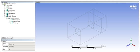
Figure 1.
DesignModeler geometry and tree outline.
For the simulations, the cylinder has a length of 30 mm, an initial diameter of 8 mm and is positioned in the centre of the anechoic layer. Under ‘Details of Body’ the anechoic and steel layers were set to solid whereas the air cavity was set to fluid. An image of the model with the tree outline can be seen in Figure 1.
Under ‘engineering data’ in the project schematic the materials required for simulation were selected and the appropriate properties set according to those given in the literature. Pure Silicon, Structural Steel and Air were chosen. For the analysis to be carried out each material used must have the properties of the density and speed of sound assigned, though damping and elasticity have also been set (again using values from the literature).
Using the ‘model’ component of the project schematic the appropriate materials were assigned to each part. Here the geometry was meshed and ‘body sizing’ applied to the anechoic layer. As shown by Hennion [5] and also Munjal [8] separately, the maximum length of each element of the model must be smaller than for the transverse wavelength in the material at the working frequency, or for the longitudinal wavelength. A longitudinal wave speed of 325 ms−1 was used in this model so the element size applied to the anechoic layer was , where 3500 Hz is the maximum value of frequency used in the harmonic analysis. In order to decrease the CPU time the element size on the steel backplate was set to the same value. The speed of sound in steel is 5960 ms−1. Therefore, satisfying a criterion using this wave speed produced elements with length greater than that of the geometry. Therefore, using the same value as the anechoic layer was more applicable while still meeting the criteria.
A patch conforming method was applied to the anechoic layer using tetrahedrons as shown in Figure 2. Since the model was not sweepable the default patch conforming method was used. As detailed in the ANSYS Meshing User’s Guide, this method supports 3D inflation, has built-in smoothness and growth control and mesh defeaturing. This was the recommended setting to improve CFD boundary resolution and improve overall mesh quality when performing the acoustic analysis [11].
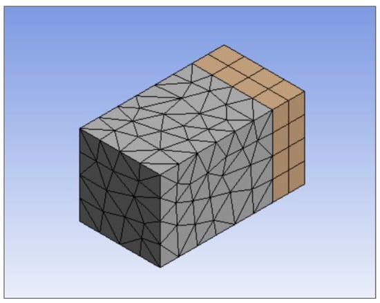
Figure 2.
Meshed Alberich geometry.
Once the geometry was imported the boundary conditions and parameters for the analysis were set in the Harmonic Acoustics project schematic. Under ‘Analysis Settings’ in the project outline, the frequency spacing was set to linear, with a frequency range from 0 to 3500 Hz in 199 intervals. To ensure coherency between the frequencies used to calculate the impedance values, the ANSYS simulation user-defined frequencies were used. For Harmonic acoustics, the only solution method available is ‘full’, which solves a collection of equations that can be expressed as:
where denotes a complex matrix or vector [11]. It uses the full system matrices to calculate solutions and so uses more CPU time and capacity. All other options were left as programme controlled which was appropriate for the current model. To allow values of absorption to be calculated the ‘General Miscellaneous’ option in ‘Output Control’ must be set to yes.
Physics regions must be set for the analysis to proceed, with parts being either an acoustics or structural physics region. For the purposes of this analysis, all three parts were set to the acoustic physics regions as the point of interest is the behaviour of the mechanical waves in the entire structure. The anechoic layer and the steel backplate were given the fluid behaviour incompressible as they are solid structures while the air cavity was given the compressible property.
A ‘Port’ boundary condition was then applied to the anechoic layer. Inserting a port allows an exterior face to be allocated as a surface on which results are evaluated, so the front face was given the ‘Port Surface’ definition while the body of the layer was labelled as the ‘Inside Surface Bodies’. To enable the impinging SONAR wave to be simulated, a ‘Port in Duct’ excitation was applied to the same surface with the port attributed as an inlet. Given that the incident wave was planar (SONAR uses planar sinusoidal waves), the wave type for the simulation was set as such. Since the absorption coefficient was calculated using a ratio of the transmitted and reflected wave amplitudes to that of the incident wave, the pressure amplitude of the applied excitation was inconsequential [9]. For the simulation a value of 1000 Pa was been used.
For the purposes of calculating the absorption coefficient of the Alberich structure the water closure need not be modelled and in its place an impedance boundary condition was applied. MATLAB was used to calculate the impedance values at all corresponding frequencies in the given range by applying the correct material properties to the following formula:
with denoting the density, the wave speed, is the length of the layer, is the angular velocity which is found using , the loss factor is given as and is the imaginary unit () [10]. The subscripts and denote the anechoic and steel layers respectively. This is a simplification of a well-known impedance transfer formula taking into consideration the low-frequency band used and the deep subwavelength of the anechoic layer owing to . The material properties used are given in Table 1 [6].

Table 1.
Material properties used in impedance calculations [6].
MATLAB returns complex values (composed of a real and imaginary part), which are the specific acoustic forms of impedance. The impedance needed was the characteristic acoustic, denoted by , which is obtained by calculating the modulus of the former. The values were then transferred to ANSYS and applied to the front face of the anechoic layer.
The ‘Rigid Wall’ boundary condition which utilises the Neumann boundary condition () or issuing the APDL ‘D’ command and setting displacements UX, UY and UZ to zero could have been used. Either of these would simulate the boundary conditions for periodicity. However, this was not needed. By using the APORT command to define a plane wave port the software automatically implemented the scattering analysis for a periodic structure. It, therefore, invalidates and ignores the ASOL command which specifies the acoustic solver with scattered field formulation [11]. Applying the periodic boundary conditions on the surfaces in the x and y planes, therefore, had no effect on the analysis (bar increasing CPU time).
In order to obtain the values of absorption, the ‘Absorption Coefficient’ object under ‘Acoustics’ in the ‘Solution’ branch of the project outline was selected as shown in Figure 3. Under ‘Definition’ the input port was set to the port on the front face of the anechoic layer. ANSYS evaluates the ratio of sound energy absorbed on the inlet port to the incident sound energy upon the surface and returns a graph and table of the results using the same frequency range and intervals as set under ‘Analysis Settings’. Other graphs were produced, such as graphs for sound pressure levels, shown later in this paper. These graphs were created in the same way as the absorption coefficient graphs by using the ‘Solution’ branch and applying the correct parameters.

Figure 3.
Acoustic analysis setup with project outline.
2.2. Computational Methodology
The simulations were run in a pre-determined sequence. The simulations assessing the effects of the cylindrical cavity diameter were done first to ensure the software returned results coherent with the theory. This formed the foundation as a comparison of the effects of the other explored factors such as the anechoic layer, steel backplate, cavity length and spherical cavity. Using the knowledge gained through the course of the simulations a final optimised model was investigated. The controlled variables and other relevant details for each set of simulations are listed below, including graphs of impedance values where relevant.
2.2.1. Cylindrical Cavity Diameter
To study the effects that cylindrical cavity diameter had on the absorption coefficient of the Alberich structure ten simulations were carried out. The initial diameter used was 8 mm, increasing in 2 mm intervals up to a value of 26 mm. Cylinder length for investigations not concerning this was 30 mm. Table 2 includes the variables that remained the same throughout the analyses, the material properties taken directly from the literature and including those already detailed in Table 1 [6].

Table 2.
Controlled variables for all simulations [10].
It was important that these properties remained constant during the simulations, as changing the lengths of the different parts affected the results. Just as important was ensuring the properties of elasticity remained constant for all simulations as stiffness was a principal factor in the acoustic response of materials. By doing this it was ensured that the results obtained were due to the change in cavity diameter alone, making them more accurate and reliable. Length of the anechoic layer was 50 mm. Values of impedance remained the same for simulations that assessed the effects of the cylindrical cavity diameter, cavity length, spherical cavity and optimised model. A graph of impedance versus frequency can be seen below in Figure 4.
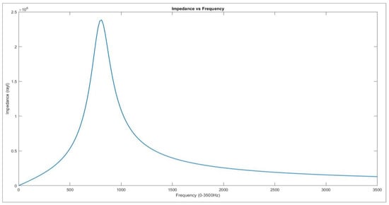
Figure 4.
Graph of impedance used for cylindrical cavity diameter simulations.
Acoustic impedance is the opposition of a medium to the motion of wave propagation and it characterises the relationship between the acting sound pressure and the resulting particle velocity. Due to this characterisation of the medium it travels in, this impedance is called characteristic acoustic impedance. As such it is an inherent property of the medium and the nature of the wave speed [3]. It should be noted that for the remainder of the paper the characteristic acoustic impedance will be referred to simply as ‘impedance’.
Referring to Figure 4, the value of impedance peaks at 810 Hz with a value of pascal seconds per meter (or rayl). This was the impedance as a result of the properties detailed and as such was specific to the material, wave characteristics and geometry. Changing some of these variables had a large impact on the impedance values gained and consequently on the acoustic behaviour of the anechoic mode.
2.2.2. Anechoic Layer
To study the effects of anechoic layer length 5 simulations were conducted, starting at 40 mm and increasing by 5 mm to a value of 60 mm. For each simulation the cavity diameter was kept at 18 mm and a length of 30 mm (chose as these were the median values in the data set). Values of impedance are shown in Figure 5.
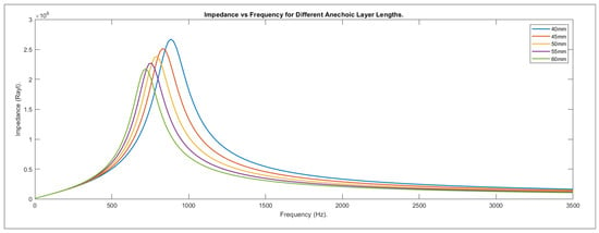
Figure 5.
Graph of impedance used for anechoic layer length simulations.
2.2.3. Steel Backplate
As shown in Figure 6, five iterations of simulations were conducted to explore the effects of steel backplate length, beginning at 5 mm and increasing in 5 mm increments to 25 mm. Cavity diameter held a value of 18 mm and the anechoic layer had a length of 50 mm to maintain consistency with the primary set of simulations and ensure results are due to the variable being explored alone.
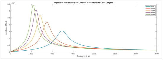
Figure 6.
Graph of impedance used for steel backplate layer length simulations.
2.2.4. Cavity Length
Diameter of the air cavity was investigated to study the effect of cavity length on the absorption of the Alberich coating. Five simulations were run, starting at a length of 22 mm and increasing in 4 mm steps to a value of 38 mm. The cavity diameter was 18 mm, anechoic layer length 50 mm, and steel backplate length 12 mm. Values of impedance used were the same as those in Figure 4.
2.2.5. Spherical Cavity
Figure 7 shows the 14 mm spherical cavity diameter model used to investigate how spherical cavity affects absorption opposed to a cylindrical cavity. Staying consistent with the previous investigations five simulations were conducted starting at a diameter of 14 mm and finishing with 22 mm. Figure 4 gives the values of impedance used for the simulations. The length of the anechoic layer remained at 50 mm and the steel backplate 12 mm in keeping with cylindrical cavity diameter and length research.
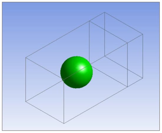
Figure 7.
ANSYS model of Alberich coating with spherical cavity.
2.2.6. Optimised Model
Using what has been learned from the previous simulations, an optimised Alberich structure was modelled focusing on achieving maximum peak absorption within the 500–1000 Hz range. Table 3 below shows the physical parameters.

Table 3.
Optimised model physical parameters.
Compared to the parameters used to investigate the effect of cylindrical cavity diameter, the length of the anechoic layer was shorter and the backplate longer in correlation with the conclusions drawn from Section 2.2.1 In order to still consider the absorption in higher frequencies and due to the minimal difference seen between the two at peak absorption, a spherical cavity had been used in place of a cylindrical one. The model was as it appears in Figure 8.
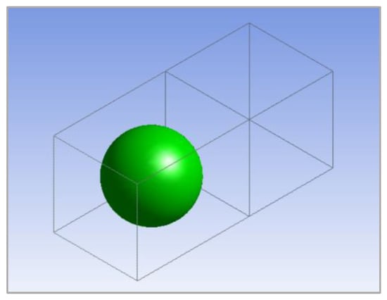
Figure 8.
Optimised Alberich coating.
3. Results
3.1. Cylindrical Cavity Diameter
For the initial air cavity diameter of 8 mm, the resulting graph of absorption vs frequency is seen in Figure 9. The first peak is seen at a frequency of 778 Hz and has an absorption coefficient value of 0.82447. Absorption then drops to near zero in a frequency range of 1500–1750 Hz, where it then begins to increase again to a second peak value of 0.61951 at 3146 Hz. The fin al value at 3500 Hz is 0.58161.
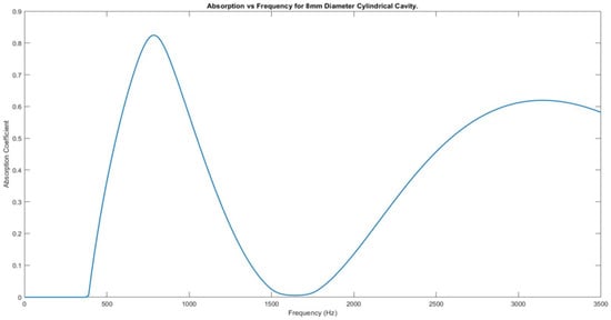
Figure 9.
Absorption against frequency for 8 mm cavity diameter.
Figure 10 shows the graphs of absorption vs frequency for ten cavity diameter sizes, ranging from 8 mm to 26 mm diameter cavity in 2 mm intervals. It can be seen that with the increase in diameter, there is a relatively small increase in peak absorption at 795 Hz and a much greater decrease in absorption at 3150 Hz. For comparison, between 8 mm and 26 mm, the peak at 795 Hz increased by 0.01293, whereas the value at 3150 Hz decreased by 0.38006. The frequency range over which there is zero absorption also increased dramatically. While the 8 mm diameter model did not reach zero absorption past 370 Hz, the 26 mm model was completely non-absorbing from 1618–2409 Hz, 23% of the total bandwidth.
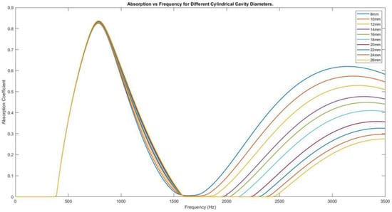
Figure 10.
Graph of absorption vs frequency for 10 different cavity diameter sizes.
Figure 11 shows the graphs of 8 mm and 26 mm cavity diameter together for comparison. It was apparent that the decrease in absorption towards higher frequencies was significantly greater compared to the increase in peak absorption at a lower frequency. To put this trend into perspective, the first peak increases by 1.55% over the simulated range, while the second peak decreases by 61.35%.
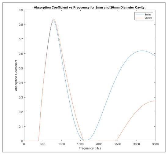
Figure 11.
Graphs of 8 mm vs 26 mm diameter cavity absorption against frequency.
3.2. Anechoic Layer
Figure 12 clearly shows that by increasing the length of the anechoic layer, the first peak not only decreased in magnitude, but was also shifted to a lower frequency. For example, 40 mm length had a first peak of 0.85871 at 880 Hz, reaching 0 between 2000 and 300 Hz, before increasing to 0.081908 at 3000 Hz. The 60 mm length model, however, had an initial peak of 0.80422 at 710 Hz and a second peak of 0.51929 at 2740 Hz.
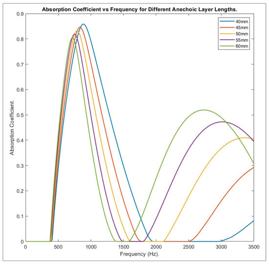
Figure 12.
Absorption against frequency for different anechoic layer lengths.
3.3. Steel Backplate
As seen in Figure 13, increasing the length of the steel backplate not only increased the value of the main absorption peak, but also shifted it to much lower frequencies. Comparing the 5 mm and 25 mm length models, the first had a value of 0.70579 at 1220 Hz, the latter a value of 0.89026 at 550 Hz. The absorption coefficient showed a 26% increase but had shifted to a lower frequency by 670 Hz.
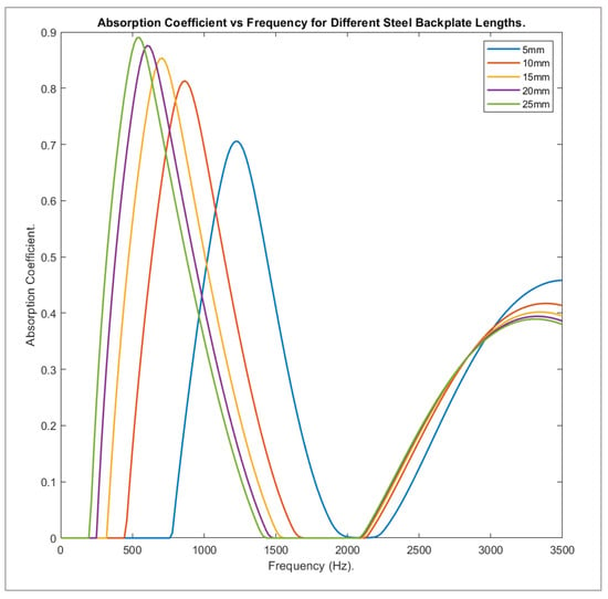
Figure 13.
Absorption coefficient against frequency for different backplate lengths.
3.4. Cavity Length
The effect of cavity length on the absorption performance of the model has been shown through simulation and the results pictured in Figure 14 on the following page. Similarly, when studying the effect of cavity diameter on absorption, it can be seen from Figure 14 that increasing cavity length marginally increased the initial peak, but greatly decreased the second. From 22 mm to 38 mm, the peak at 795 Hz increased by 0.02207, whereas the value at 3500 Hz was 0.44482 lower.
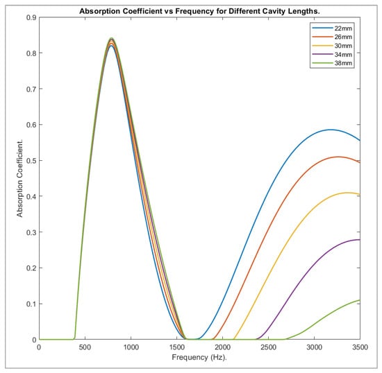
Figure 14.
Plot of absorption vs frequency for different cylindrical cavity lengths.
3.5. Spherical Cavity
Much in the same way as with the cylindrical cavity, the presence of the spherical cavity adjusted the effective stiffness of the anechoic layer. As shown in Figure 15, the 14 mm model had a peak value of 0.7932 at 780 Hz, followed by a second peak of 0.77838 at 2930 Hz, while the 22 mm model had a first peak of 0.81117 and a second of 0.63805 at the same frequencies.
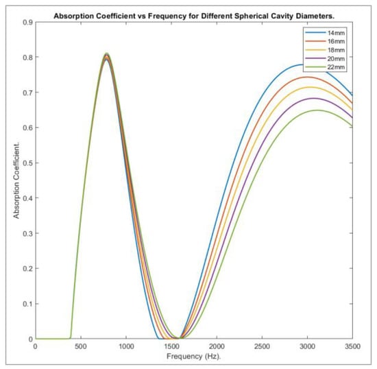
Figure 15.
Graph of absorption vs frequency for different spherical cavity diameters.
From the numbers provided, it was seen that for the smaller diameter, the second peak value was nearly of the same magnitude as the first, a fact made clearer when looking at the following graph of results.
Compared to the absorption trends produced by the cylindrical cavity model, the model containing spherical cavities showed much greater absorption at the higher end of the frequency range, while absorption at the lower frequency was slightly less. The margin of change between diameter sizes, however, remained slight for the initial peak and, again, showed greater difference for the second. When the same diameter was considered, the volume of air in the cylindrical cavity was a factor of ten greater than that of the spherical cavity.
3.6. Optimised Model
Once the appropriate values of impedance were calculated using MATLAB and applied to the model seen in Figure 8 (Section 2.2.6), the corresponding graph of absorption against frequency was plotted. For comparison, the 26 mm diameter cylindrical cavity model has been included in the same graph (Figure 16).
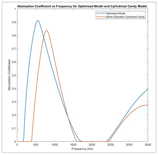
Figure 16.
Absorption vs frequency for the optimised model and 26 mm diameter cylindrical cavity model.
It is clear from Figure 16 that the absorption result obtained from the optimised model (referred to herein as model one) was much more effective than from the standard Alberich structure (model two). Peak absorption in model one occurs at 550 Hz, with a value of 0.91129, compared with model two, which peaks at 795 Hz, with a magnitude of 0.83689. That presents an increase of 0.0744 and a frequency shift of 245 Hz towards zero. The bandwidth over which there is no absorption is 26% less for model one and the absorption at 3500 Hz also increased by a magnitude of 0.1195, from 0.27429 to 0.39369. Model one covers the entire 100–1000 Hz bandwidth, unlike model two, which displays zero absorption up until 370 Hz.
4. Discussion
Several factors were used to explain the trends seen in the results section of the paper. These are listed individually, and explicit connections are drawn between them and the simulations.
4.1. Resonance of the Cavity
Acoustic resonance occurs when a system vibrates at a particular frequency, called the resonant frequency. Resonance is caused by the transfer between sound pressure and flow energy and is determined by the geometry and material properties of the object. For the cylindrical air cavity, the resonant frequency is predicted by:
It was clear that this value was nowhere near the peak frequency and so it was reasonable to conclude that the resonance of the air cavity was not responsible for the peak absorption of the anechoic coating [10], as was seen in all simulations conducted.
4.2. Resonance of Anechoic Layer
Section 3.3 shows that the increased length of the steel backplate (and, therefore, mass) decreased resonant frequency, owing to the equation:
The air cavity within the anechoic layer was extruded by the normal displacement of the steel plate [7]. When more mass was added to the steel backplate (by increasing length), the extension of the anechoic layer was increased, which led to further shear and compressive deformation of the air cavity. As a result, there was a greater mode shift to transverse waves, increasing their attenuation. Peak absorption of the model at lower frequencies increased with the length of the backplate as a result of this, while being more closely clustered at higher frequencies. (The results achieved were consistent with those produced in previously published papers, showing that as backplate length increased, the frequency of the main absorption peak decreased [12]).
4.3. Impedance Mismatch
Acoustic mediums, in which the speed of sound differs, commonly do not have the same impedances, meaning when a sound wave strikes the interface between them, it encounters an impedance mismatch. Consequently, some of the impeding wave is reflected and some transmitted into the second medium. When the system is not operating at resonant frequency, high reflection occurs due to discontinuous acoustic impedance along the axis of sound propagation. In the case of the anechoic model used, the impedance mismatch arises between the silicone layer and the air cavity, and the silicone layer and the steel backplate. As demonstrated by the ‘bell-in-vacuum’ experiment conducted by Athanasius Kircher [13], transmission from a low- to high-density medium, and vice versa, is not efficient. The greater difference in density and the impedance mismatch caused less transmission of propagating waves and increased reflection. Hence, the differing densities and wave speeds in the components of the anechoic model have an inherent impact on the absorption coefficient seen. In order to reduce overall reflection and increase transmission into the silicone layer and metal backplate, the densities and wave speeds must be closely matched to those of air [13].
Impedance mismatch also reduces the bandwidth for efficient acoustic transmission and so may be a key factor when explaining the decrease to complete non-absorbance seen in all simulations. By matching the impedance between air, silicone and steel peak absorption, this would occur over a greater frequency range.
Though impedance is a key factor, when comparing the graph for impedance in Figure 4 and absorption in Figure 9 (Section 2.2.1 and Section 3.1), the following similarities were drawn: the first peak in both graphs occurred at around 800 Hz, and maximum values appeared only 32 Hz apart. This would suggest that the two are correlated directly, with greater impedance resulting in a higher absorption coefficient. However, it was clear that this was not the case when the results were analysed further. Unlike Figure 4, where the value decreases steeply until around 1500 Hz and levels off to a low negative gradient, the behaviour demonstrated by the absorption plot in Figure 9 was completely divergent. Rather than tending towards zero, the graph reached a minimum before increasing again to form a smooth curve. A second peak occurred at 3100 Hz and declined again, until the upper limit of the frequency was reached.
4.4. Stiffness
The silicone and steel backplate model was analogous to a mass spring resonator, where the silicone acts as the spring and backplate as the mass [7]. When the silicone layer is subjected to the impeding planar wave, the layer is forced to compress and extend longitudinally. As with a mass–spring system, the frequency of oscillation can be altered by changing the stiffness of the silicone layer.
Reducing the stiffness of the layer also affects peak absorption values. The relationship between stiffness and the amplitude of oscillation is given by Hooke’s law:
where is the force applied and is the displacement of the spring, or in this instance, the compression/elongation length of the silicone layer. By rearranging Equation (2), it is shown that by reducing the stiffness, a greater displacement is realised for the same force applied. This was seen looking at the results in Section 3.2, where the anechoic layer length increased and the stiffness decreased at a proportionate rate. The larger the spring constant, the smaller the extension and period of vibration of the layer for the same force applied; hence, when looking at Figure 13, a second peak was realised at a lower frequency, when layer length was reduced.
As a result of decreased stiffness, the increased vibration of the silicone layer dissipates a greater amount of the impeding sound energy, converting more into heat energy. The results in Section 3.2 suggest this is not the most prominent cause of peak absorption.
Another factor to consider in relation to the stiffness of the silicone layer is the shear deformation due to the oscillation of the air cavity. Due to the pressure wave propagating through the silicone layer, the walls of the cavity are forced to move in and out, resulting in a mode conversion from longitudinal to transverse waves. Transverse waves dissipate quicker in the rubber material, resulting in greater dissipation of the acoustic energy [7].
4.5. Volume Fraction of Air
The volume fraction of the air cavity is given in Equation (4) below [10]:
In the above equation, represents the radius of the cavity, denotes the length of the cavity, the length of the anechoic layer and the period of the cavity (in this case 30 mm).
The result of increasing volume fraction is clear when comparing the transmission loss (difference between incident and transmitted power) for two models containing cavities of different diameter sizes. Figure 17 shows the graphs obtained from two such simulations.
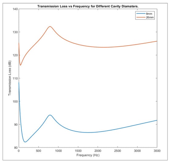
Figure 17.
Transmission loss for anechoic models with different cavity diameters.
Though both graphs in Figure 17 follow the same trend, it is clear to see that the model with the 26 mm diameter cavity produced a much greater transmission loss than that of the 8 mm diameter cavity. There was little shift in frequency between the features of the two graphs. However, the magnitude of the transmission greatly increased. By increasing the cavity diameter, thus, the volume fraction of air, the attenuation of the anechoic layer was greatly increased. This led to much higher values of acoustic transmission.
This factor is clearly expressed analysing the absorption trends produced by the cylindrical cavity model compared to the model containing spherical cavities. Simulations in Section 3.6 showed much greater absorption at the higher end of the frequency range, while absorption at the lower frequency was slightly less. The margin of change between diameter sizes, however, remained slight for the initial peak and, again, showed greater difference for the second. When the same diameter was considered, the volume of air in the cylindrical cavity was a factor of ten greater than that of the spherical cavity. Thus, although the attenuation become greater due to the greater volume fraction of air within the layer and stiffness become less, the rubber absorption decreased and there was less extension of the anechoic layer closest to the backplate, in relation to cylindrical cavities. This explained why, when comparing spherical and cylindrical cavity results, initial peak was greater and second peak lower for the latter of the two.
4.6. Velocity and Pressure
Figure 18a–d showed the acoustic total velocity for two different cavity diameter size Alberich coatings. ‘a’ and ‘b’ showed the vector plots generated by the 8 mm diameter cavity, before and after 790 Hz; ‘c’ and ‘d’ show likewise for a 26 mm diameter cavity.
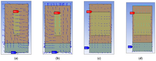
Figure 18.
Total acoustic velocity of Alberich coating with 8 mm diameter cavity before (a) and after (b) 790 Hz, and 26 mm diameter cavity before (c) and after (d) 790 Hz.
As seen in all the images in Figure 18, there is a large shift in both velocity magnitude and direction that occurred at the aforementioned frequency. This was the same frequency at which peak absorption happened in all of the simulations.
The maximum value of velocity in both the 8 mm and 26 mm diameter cavity was found at the front interface, between the air cavity and anechoic layer, with values of 0.013517 and 0.0041764 ms−1, respectively. It is reasonable to suggest that the first absorption peak was due, at least partly, to this increase in velocity.
Research conducted on sound absorption at high sound pressure levels revealed that, with increasing pressure, the flow velocity also increased [12]. As a result, the surface acoustic resistance and reactance also increased, leading to greater absorption values.
Though it can be seen that the model with the smaller cavity diameter had a greater flow velocity by a factor of ten, more of the flow was of higher velocity in the bigger cavity model (there was a more substantial increase over a larger portion of the total acoustic velocity). Furthermore, seen from Figure 19, with smaller cavity diameter, the pressure was not only greater at maximum and minimum points, but it also had higher values over a greater length of the model.
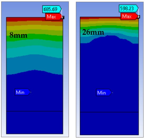
Figure 19.
Pressure for 8 mm and 26 mm diameter.
Since this change in direction and increase in the magnitude of flow velocity occurred at exactly the same frequency as the peak absorption, it was clear there was a causality. The greater these changes, the greater the absorption value realised.
4.7. Rubber Absorption
The prevailing factor when analysing the peak absorption at the lower frequency alone, in all simulations, was the absorption of compressional and transverse waves offered by the material properties of the rubber. For example, when looking at Section 3.2, the shorter time between compression and extension of the model, as it was subjected to the planar wave, was responsible for achieving a much bigger second peak within the frequency range used; however, the rubber absorption, because of greater stiffness, caused the larger initial peak seen by the 40 mm model.
Section 3.4 is another example; as the length of the cavity increased, the attenuation of the anechoic layer increased, while the rubber absorption decreased [13]. This led to the growth in absorption coefficient seen at the lower frequency and the decrease at higher frequencies.
All these individual factors were applied conjointly to explain the behaviours seen in the simulations and results given in Section 3.1. It was expected that an increased absorption coefficient was directly proportional to an increased cavity diameter, yet it was clear that after a certain frequency, this was not the case. While the decrease in stiffness due to a higher volume of air did not aid in the dissipation of sound energy, there were also adverse effects that can account for this loss in absorption towards higher frequencies. In Section 4.4, it was explained that shear deformation occurs near to the air cavity, resulting in a mode shift from longitudinal to transverse waves [7]. The dissipation of transverse waves in a rubber material was much greater than that of longitudinal waves, or the dissipation of similar waves in air. However, absorption of compressional waves also needed to be considered, and when rubber absorption was introduced, the absorption coefficient of the model was greatly increased in higher frequencies [12]. While a higher volume of silicone increased the stiffness of the anechoic layer, resulting in less energy dissipation through vibration, it also correlated to greater rubber absorption through the dissipation of transverse and compressional waves. It was, therefore, solidified that this rubber absorption was the prevailing factor, when explaining the trend seen in varying cavity diameter; the reduction in rubber volume that comes with increasing cavity diameter was responsible for the drop in value seen at 3150 Hz, made clear by Figure 10 and Figure 11.
Although the rubber absorption of compressional and transverse waves become prevalent at lower frequencies, other factors took over to produce the increase in peak absorption at 795 Hz. Previously it has been shown that there was a major shift in flow velocity magnitude and direction that occurred at the same frequency as peak absorption.
The speed of sound is quicker in air than in silicone, so as the volume of air increased, the overall acoustic velocity within the model also increased. As a result, the static flow resistance was no longer constant and instead changed with the flow velocity; this, in turn, resulted in greater acoustic reactance and resistance, realising higher absorption coefficients. When decreasing the flow resistance by enlarging the cavity diameter, it was shown that absorption coefficient at low frequencies was heightened, a trend also displayed by the simulations conducted in this paper [14].
The results achieved also supported the idea that the model acted as a mass spring system (see Figure 20) and that decreased stiffness in the anechoic layer increased the peak absorption [7]. As has been discussed, each 2 mm increase in cavity diameter increased the absorption coefficient at 795 Hz by 0.001293 on average.
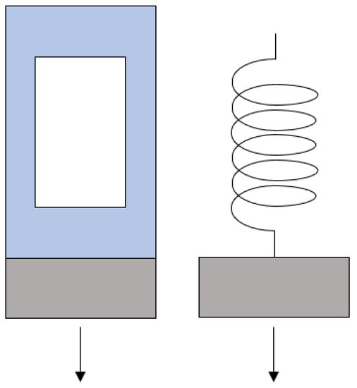
Figure 20.
Alberich structure side by side to mass-spring oscillator. Arrows represent direction of applied planar wave (force).
It was important to support the absorption results by looking at other acoustic properties, such as return loss. An image comparing the return loss results achieved by models containing 8 mm and 26 mm diameter cavities can be seen on the following page (Figure 21). Return loss is the difference between the incident and reflected sound power on a given inlet port; in this case, the front face of the anechoic layer. Both of the first peaks on the graph occurred at 600 Hz, with values of 9.9879 and 10.087 dB for the 8 mm and 26 mm models, respectively. Both graphs then decreased to zero, before again increasing to values of 5.2596 and 1.8946 dB. Though there are differences, the trend seen in the return loss graph was very close to that of the absorption plot. There was a direct link between the sound absorbed by a surface and the sound reflected by it; as absorption increased, the number of waves reflected from it decreased. Hence, when studying the return loss, it was seen that when the absorption coefficient peaked and troughed, the difference in incident and reflected sound on the surface did the same.
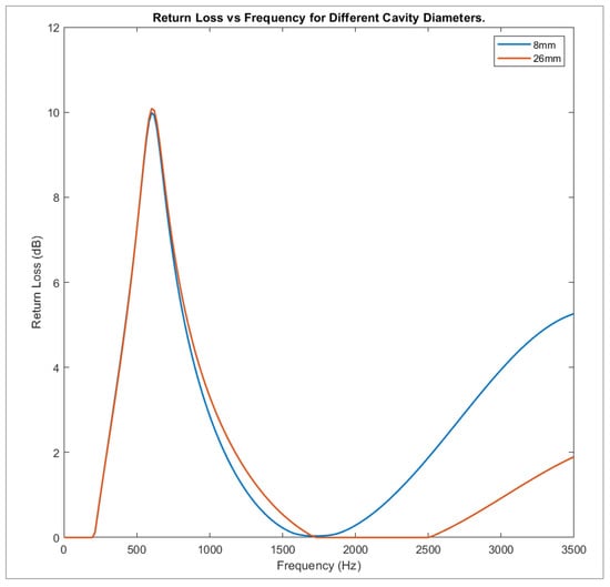
Figure 21.
Return loss plots for two different cavity diameters.
This result verified the conclusions taken from the graphs in Section 3.1, that increased cavity diameter increased the acoustic absorption of the Alberich coating at the lower frequency while decreasing it at higher frequencies.
5. Conclusions
The simulations conducted throughout the course of the research undertaken and the results given in this paper showed how varying multiple parameters affected the absorption coefficient and other acoustic properties of an Alberich coating.
Preliminary simulations investigating the effects of cylindrical cavity diameter were conducted and it was concluded that the increase in diameter resulted in a marginal increase in absorption at a lower frequency and a relatively greater decrease at a higher frequency. This was the expected result and so showed that the model worked correctly.
Following this, four further sets of simulations, concerning different parameters and, ultimately, an optimised Alberich coating, were carried out. As a result of the knowledge gained throughout the research, the optimised model contained a spherical cavity with 26 mm diameter, 40 mm long anechoic layer and 30 mm long steel backplate, producing an absorption peak at higher and lower frequencies, greater than that of the 26 mm cylindrical cavity diameter model. The goal of improving the acoustic stealth of a submarine through the use of an optimised Alberich coating was achieved.
The results were explained in terms of the stiffness of the anechoic layer and steel backplate, respectively, the rubber absorption of the anechoic layer, impedance mismatch and other factors, though it was concluded that rubber absorption was the most prominent in explaining the absorption behaviour.
The real-world application of the research conducted is very beneficial, not only to the United Kingdom’s Naval Service, but also the security of her shores. The conclusions drawn from the simulations could help to better design Alberich coatings, to more efficiently improve the acoustic stealth of submarines, to ensure that they can continue their duties, undetected by hostile forces. The optimised model showed that the coating could be tailored to produce maximum absorption in a desired frequency range and can be used to combat the newly developed low-frequency SONAR.
Author Contributions
Writing, Conceptualization, Methodology: C.D.; Supervision, Review: N.P.; Editing: C.D. and N.P. All authors have read and agreed to the published version of the manuscript.
Funding
This research received no external funding.
Conflicts of Interest
The authors declare no conflict of interest.
References
- Eggler, D.; Kessissoglou, N. Active acoustic illusions for stealth and subterfuge. Sci. Rep. 2019, 9, 13596. [Google Scholar] [CrossRef] [PubMed]
- Li, B.; Peng, Z.; Wen, H.; Fan, J.; Song, H. Research on the Optimization Design of Acoustic Stealth Shape of the Underwater Vehicle Head. Acoust. Aust. 2020, 48, 39–47. [Google Scholar] [CrossRef]
- Tang, J.H. Acoustic propagation characteristics of heteromorphic metamaterials. AIP Adv. 2018, 8, 105305. [Google Scholar]
- Méresse, P.; Audoly, C.; Croënne, C.; Hladky-Hennion, A.C. Acoustic coatings for maritime systems applications using resonant phenomena. Comptes Rendus Mec. 2015, 343, 645–655. [Google Scholar] [CrossRef]
- Hladky Hennion, A.-C.; Decarpigny, J.N.A. Analysis of the scattering of a plane acoustic wave by a doubly periodic structure using the finite element method: Application to Alberich anechoic coatings. J. Acoust. Soc. Am. 1991, 90, 3356–3367. [Google Scholar] [CrossRef]
- Fu, X.; Jin, Z.; Yin, Y.; Liu, B. Sound absorption of a rib-stiffened plate covered by anechoic coatings. J. Acoust. Soc. Am. 2015, 137, 1551–1556. [Google Scholar] [CrossRef] [PubMed] [Green Version]
- Meng, H.; Wen, J.; Zhao, H.; Lv, L.; Wen, X. Analysis of absorption performances of anechoic layers with steel. J. Acoust. Soc. Am. 2012, 132, 69–75. [Google Scholar] [CrossRef] [PubMed]
- Easwaran, V.; Munjal, M.L. Analysis of reflection characteristics of a normal incidence plane. J. Acoust. Soc. Am. 1993, 93, 1308–1318. [Google Scholar] [CrossRef]
- Panigrahi, S.N.; Jog, C.S.; Munjal, M.L. Multi-focus design of underwater noise control linings based on finite element analysis. Appl. Acoust. 2008, 69, 1141–1153. [Google Scholar] [CrossRef]
- Zhong, J.; Zhao, H.; Yang, H.; Wang, Y.; Yin, J.; Wen, J. Theoretical requirements and inverse design for broadband perfect absorption of low-frequency waterborne sound by ultrathin metasurface. Sci. Rep. 2019, 9, 1181. [Google Scholar] [CrossRef] [PubMed]
- ANSYS, Inc. Harmonic Acoustic Analysis. 14 December 2020. Available online: https://ansyshelp.ansys.com/account/secured?returnurl=/Views/Secured/corp/v202/en/wb_sim/ds_harmonic_acoustics.html (accessed on 6 September 2021).
- Zhou, F.; Fan, J.; Wang, B.; Peng, Z. Absorption Performance of an Anechoic Layer with a Steel Plate Backing at Oblique Incidence. Acoust. Aust. 2018, 46, 217–327. [Google Scholar] [CrossRef]
- Britannica. Impedance. 23 January 2021. Available online: https://www.britannica.com/science/sound-physics/Impedance (accessed on 20 October 2021).
- Ketabdari, S.H. Numerical simulation of a viscoelastic sound absorbent coating with a doubly periodic array of cavities. Cogent Eng. 2018, 5, 1529721. [Google Scholar]
Publisher’s Note: MDPI stays neutral with regard to jurisdictional claims in published maps and institutional affiliations. |
© 2022 by the authors. Licensee MDPI, Basel, Switzerland. This article is an open access article distributed under the terms and conditions of the Creative Commons Attribution (CC BY) license (https://creativecommons.org/licenses/by/4.0/).