1. Introduction
For overhead transmission lines, specific cables are used. They are aluminum conductors of different types, mainly all-aluminum alloy conductors (AAAC) or aluminum conductors reinforced with steel wires (ACSR), despite the emergence of new types of conductors and coatings [
1,
2,
3,
4,
5]. More specifically, Aluminum Conductor Steel-Reinforced (ACSR) are conductors composed of a central core of steel strand surrounded by layers of aluminum wires [
5]. The steel core provides mechanical strength, while the aluminum wires offer excellent conductivity. The steel strands are typically protected against corrosion with a galvanization layer.
Despite their durability, conductors can experience degradation over time due to various factors that can considerably affect their lifetime. Main damage mechanisms are identified as corrosion, wear and fretting fatigue from in situ expertise or laboratory studies [
6,
7,
8,
9,
10,
11,
12,
13,
14]. Corrosion damage is an important phenomenon of degradation of conductors with multiple consequences on their mechanical, physicochemical and electrical properties. Different types of corrosion can be present at the surface of the wires. The uniform corrosion consists of a global reduction in sections of wires. This mainly concerns the galvanizing layer of steel wires and the inner layer of aluminum wires, as reported by several authors in the most aggressive atmospheres [
15,
16,
17,
18,
19]. Pitting corrosion appears locally at the contacts between the wires. This form of corrosion is more dangerous than uniform corrosion, with growth in depth of the pits in the wire leading to a rapid decrease in mechanical resistance [
20]. The occurrence and time-dependent severity of pitting depends on several parameters of the conductor [
21]. In observations on aged conductors made by Kreislova et al., the average depth of a pit is 50 μm and can reach between 150 and 200 μm for aluminum in corrosive conditions [
6].
When the galvanization layer has been damaged, direct contact exists between aluminum and steel wires at interwire zones that leads to the degradation of aluminum. This galvanic corrosion particularly concerns the aluminum wires of the internal layer, which are more degraded than those of the external layer, as observed by Kim et al. [
22]. The influence of galvanic corrosion was also highlighted by Forrest et al. with a significant loss of section of aluminum wires in contact with steel wires in marine environments [
14]. In this study, the inner aluminum wires corrode much faster than the outer aluminum wires.
This type of corrosion is more damaging compared to uniform corrosion in the case of bimetallic electrical conductors. According to studies conducted on this type of cable, it is difficult to predict the damage of these conductors in corrosive environments, given the different mechanisms and the complexity of these cables. Several results in the literature on a priori similar cables are contradictory in terms of corrosion and other results highlight durability in contradiction with the severity of the climatic environments to which the samples were exposed [
23,
24]. Some cable/wire parameters appear to be not fully taken into account or even improperly weighted with regard to corrosion. Considering the different mechanisms present and their possible coupling, the concept of the study is to better understand and quantify the influence of the major parameters, studied separately, on corrosion degradation.
Thus, ACSR wires and strands have been evaluated in corrosion by the mean of accelerated corrosion tests. This made it possible to obtain corrosion damage for ACSR conductors with acceptable test durations. The specific objective of this paper is to evaluate the effect of grease and conductor geometry on the mechanical properties of aluminum strands composing the envelope of ACSR conductors. The materials and methods are first introduced, and then the results concerning microstructural and corrosion products are presented. Finally, tensile, fatigue and torsion test results are presented to examine the effect of corrosion on aluminum strands.
2. Materials and Experimental Procedures
The conductors studied for corrosion were greased and ungreased ACSR strands with a diameter of 19.6 mm. They were made up of a central steel core of 2.8 mm in diameter, a layer of 6 steel wires of 2.8 mm in diameter and two layers of aluminum wires (12 and 18) of 2.8 mm in diameter. For selected strands, the grease (OCG 4500) fully covered the steel core wires and partially covered the internal layer of aluminum wires. Two types of aluminum wires, those coming from a full strand and others being single wires (1350 series), have been tested for corrosion. The elemental chemical composition of aluminum wires is provided in
Table 1.
The length of strands and wires samples is 500 mm. A collar is placed at each end of the strand to prevent untwisting. The specimens are protected at their ends with a cap filled with anti-corrosion gel (
Figure 1). This prevents corrosion from initiating at the sample ends.
Corrosion tests were carried out using an ASCOTT CC1000iP (Ascott Analytical, Tamworth, UK) salt spray chamber. This equipment makes it possible to simulate a saline environment for accelerated corrosion tests with control of the temperature, humidity level and injection rate of the saline solution. Each sample was spaced at least 20 mm from the edges of the chamber and from other samples.
Based on ISO 9227 and ISO 16701 standards, the corrosive medium chosen was a 5% mass NaCl solution with a pH of 6.9 [
25,
26]. The temperature was kept constant at 50 °C during the tests, and the humidity level varied cyclically between 50% RH and 95% RH. The accelerated corrosion procedure uses the repetition of two basic cycles in sequence, as defined in
Figure 2. The basic cycle A includes three saline spray periods of 15 min. Then the basic cycle B without spray is performed six times to form a global cycle of 84 h. This global 84 h cycle was repeated until the end of the test. Different durations were fixed: 42, 84, 168, 210, 252 and 336 days.
After the corrosion test, the samples were cut and prepared for the evaluation of microstructural surface and profile; RAMAN analysis for chemical corrosion products; and mechanical properties. Wires for microstructural observations and RAMAN are cut into samples of 10 mm ± 1 mm. The samples are hot-mounted by compression using a phenolic compound. After the mounting step, the samples are polished to a mirror finish (oxide polishing suspension of 0.03 micrometer) to achieve the desired surface finish for metallographic observations and analyses.
The test samples were observed using a Hitachi SU5000FEG SEM coupled with EDS analysis (Hitachi High-Tech Europe, Meudon la Foret, France) on longitudinal and transverse sections. RAMAN analyses were carried out on these samples using a Horiba Jobin Yvon LabRAM HR Evolution spectrometer (HORIBA FRANCE SAS, Vénissieux, France) equipped with a microscope Olympus BX41 (Olympus Corporation, Tokyo, Japan) and a Peltier-based cooled charge-coupled detector (CCD). A solid-state diode-pumped green laser (532 nm, 17 mW power) was selected with variable acquisition time adjusted between 30 and 80 s to optimize the signal-to-noise ratio. A long Working Distance 50× objective, with a spectral resolution estimated at 0.5 cm−1, was used.
The mechanical tests concerned non-corroded (as-received) and corroded wires, either individual single or extracted from the strand. The tensile tests were performed on a hydraulic press with flat jaws and at a rate of 1 mm/min until rupture. The tension force on aluminum wires was measured by a 5.0 kN load-cell, and the elongation was measured by an extensometer clipped on the wires with an initial gauge length of 25 mm.
A specific test bench was used for the fatigue test in which the test wire is fixed between two hydraulic jacks. For fatigue tests, one jack produces alternating tension while the position of the second jack is locked. The average tension load for the fatigue test, T0 = 449 N, is the tension in an aluminum wire when the complete ACSR strand is loaded at 25% of its tensile resistance. The alternating load, ΔT = 247 N, was determined from several preliminary fatigue tests on undamaged wires aiming for a lifetime of a few million cycles (A. Rondineau [
27]). The fatigue loading was a sine waveform with peaks at T0 ± ΔT (202 N and 696 N) at 24 Hz up to failure or to 5 million cycles.
The torsion test procedure is based on the International Standard ISO 7800-2012, but the tests were performed in a vertical position [
28]. The upper end is connected to a rotating arm, allowing the twisting of the sample, and the lower end is connected to a 1.3 kg mass and is locked in rotation. The number of turns before failure is used to estimate the torsional ductility of the sample.
3. Microstructural Evolution After Corrosion
3.1. Single Wires
When comparing as-received (
Figure 3a) and corroded individual wires, no corrosion is noted at the surface of the wires for up to 252 days (
Figure 3b). However, for the longest duration, 336 days, two pits are observed attesting to the beginning of corrosion (
Figure 3c). The depth and width of these pits are, respectively, 22.51 μm and 56.67 μm. They are located in the upper part of the section, the most exposed to corrosion.
3.2. Influence of the Location of the Wires Layer in the Strand
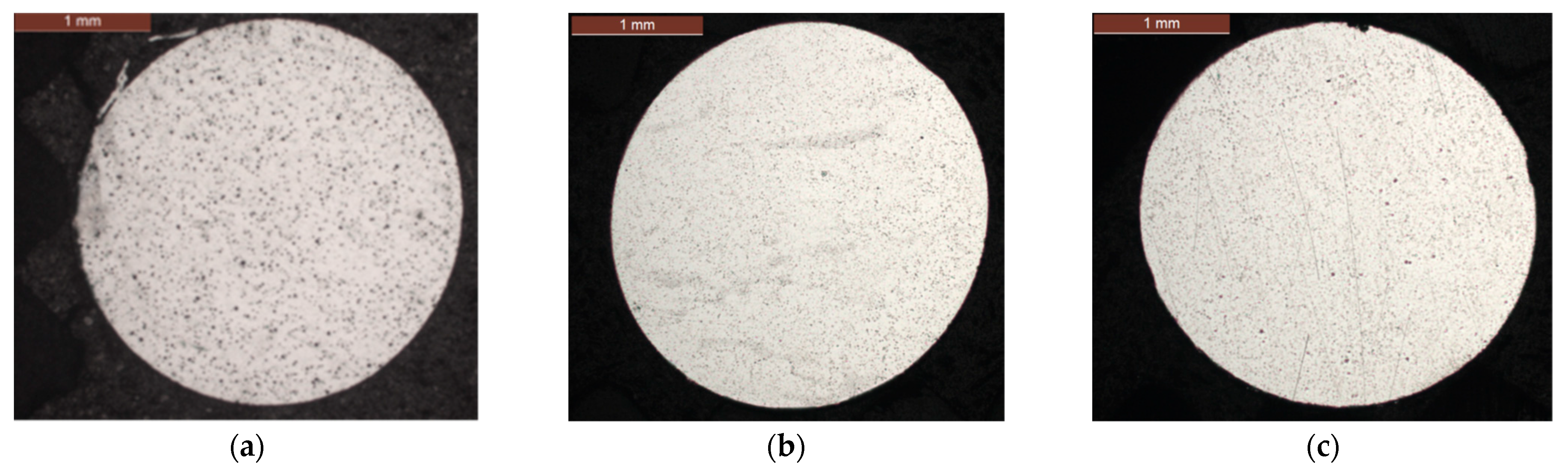
The corrosion behavior of the ungreased wires of the internal and external layers is different. In the external layer, corrosion only appears after 252 days, with the appearance of a few corrosion pits (
Figure 4b). These pits may correspond to an aluminum–aluminum contact between the two layers of aluminum. At 336 days, the top of the wire has more corrosion defects with an average pitting depth of 100 µm (
Figure 4c). This local corrosion may correspond to uniform corrosion of the aluminum since this area is directly exposed to chlorides.
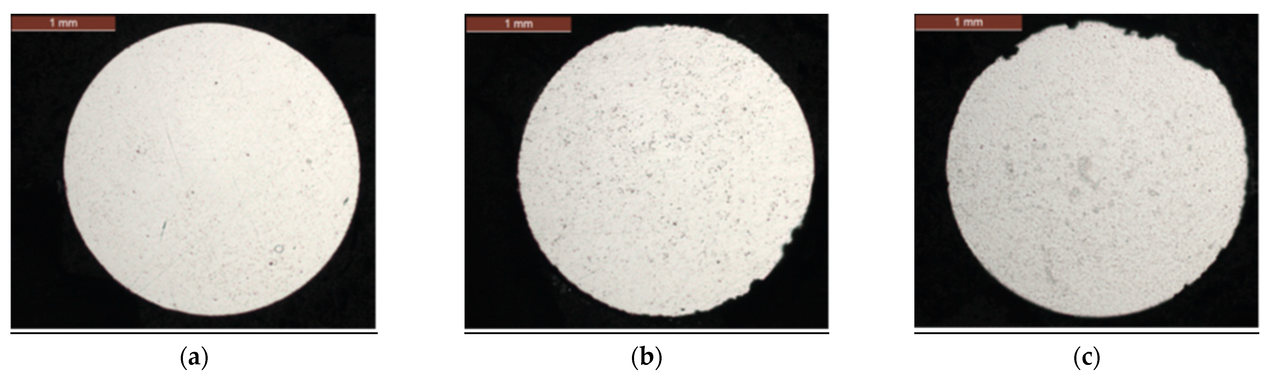
In the internal layer, pitting corrosion appears on the surface of the wires at the contact zones between aluminum layers at 168 days, then develops widely over the next durations (
Figure 5a). At 252 days and 336 days, a new type of localized corrosion is evidenced that corresponds to the loss of the galvanization layer on the surface of the steel wires (
Figure 5b,c). Indeed, observations on the galvanized steel wires during this corrosion test exhibited a complete degradation of the zinc coating for the ungreased steel wires [
29]. Thus, the internal aluminum wires are exposed to galvanic corrosion by direct contact between aluminum and steel.
These two types of localized corrosion have different dimensions, as illustrated in
Figure 5c. Galvanic corrosion generates larger defects in depth and surface with an average pitting depth of 250 µm.
3.3. Influence of the Grease on Wire Corrosion
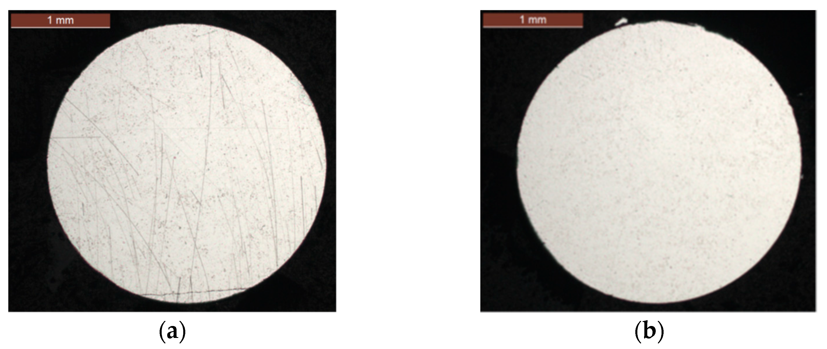
In the presence of grease in the strand, the aluminum wires of the internal and external layers are not corroded regardless of the test duration (
Figure 6). This confirms a high resistance to corrosion up to at least 336 days of exposure to accelerated corrosion conditions when the wires are greased.
This protection provided by grease was also observed by I. Ito et al. for ACSR conductors exposed to accelerated corrosion [
30]. The authors deliberately degraded the properties of the grease inside the conductors, which were then exposed to corrosion. They found that the strand begins to corrode when the oil content of the grease decreases to about 50% mass, losing its protective effect.
4. Analysis of Corrosion Products
The aluminum wires were first analyzed in energy dispersive X-ray spectroscopy (EDS) through Scanning Electron Microscopy (SEM) to obtain qualitative information about chemical elements present on the surface of aluminum wires.
Figure 7a corresponds to a magnification of a metallographic section of a wire corroded for 210 days. We observe the presence of a first layer of 30 µm average thickness on the surface of the aluminum wire as well as a second layer of average thickness of 10 µm internal to the metal substrate. In that same area, EDS analyses were carried out. A first concentration of oxygen is observed on the surface of the wire (
Figure 7c). A second concentration is visible, combining oxygen and aluminum as chemical elements (oxides/hydroxides) (
Figure 7b,c). The chlorine element is very little present and only in the outer corrosion layer of the sample. T.E. Graedel et al. have identified a three-layer microstructure composed of aluminum that is oxidized, then a corrosion layer and a surface contamination layer [
31]. Chloride-containing species can be localized in the corrosion layer (
Figure 7d).
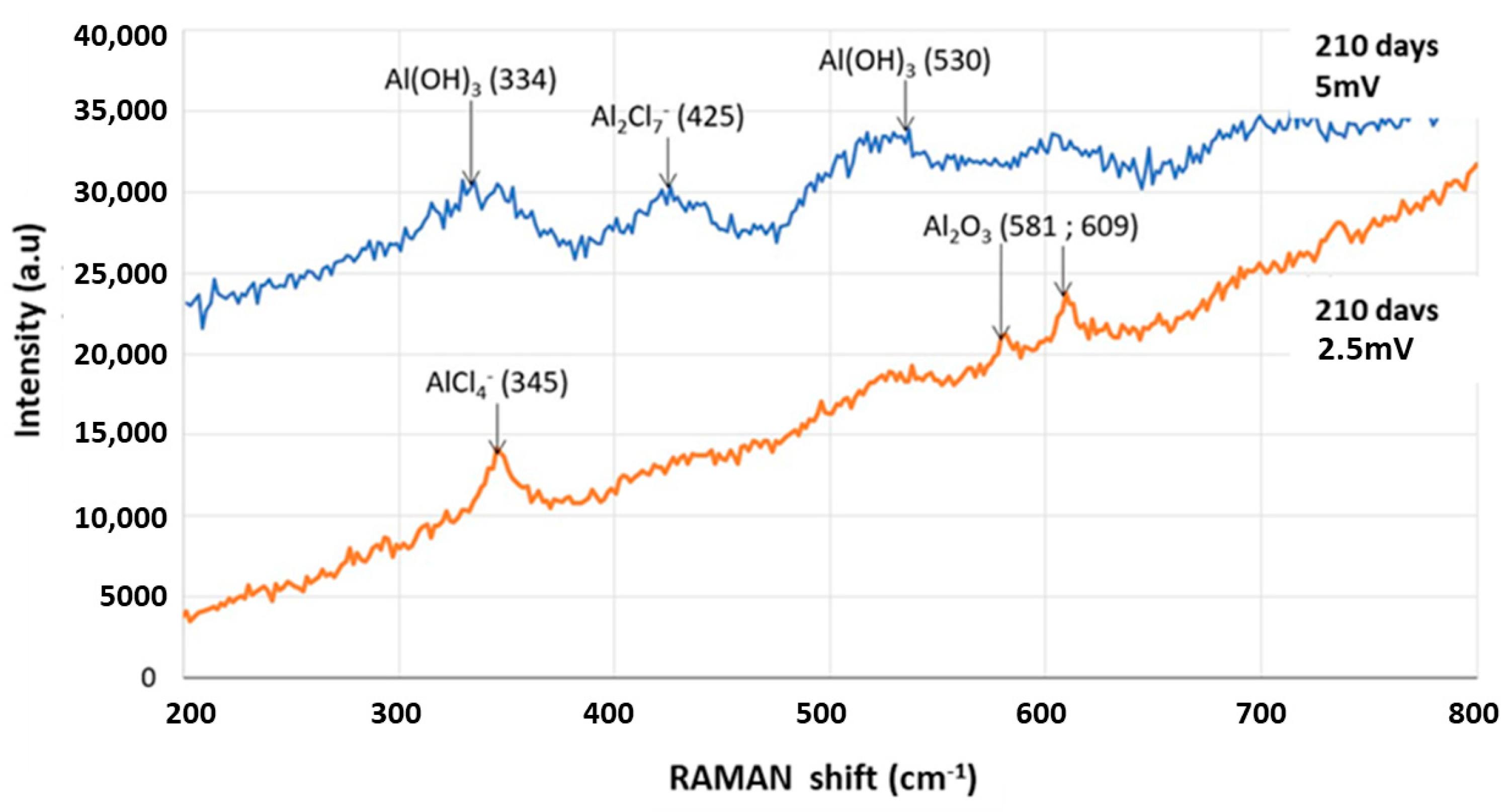
In addition, a RAMAN spectroscopy analysis is carried out on the same wire to obtain information on the nature of the corrosion products formed on the aluminum wires. In order to avoid excessive heating of the corrosion products during analysis, the laser power was limited to 2.5% of the maximum (thus ~0.5 mW). With this precaution, no local heating effects have been observed.
Longitudinal and transverse cross-sections were analyzed to obtain a comprehensive analysis of all products formed on aluminum.
Several corrosion products are identified (characteristic peaks) on the surface of the wires, such as alumina (Al
2O
3) and aluminum hydroxide (Al(OH)
3), as can be seen in
Figure 8. RAMAN spectra were acquired by varying the laser power, 2.5 and 5 mW, for better identification of corrosion products. These corrosion products were also detected by XPS spectroscopy by Peng et al. on samples of pure AA1060 aluminum exposed in a marine atmospheric zone [
32]. The authors explain by a description of the reaction mechanisms that the main corrosion products formed are (Al
2O
3) and (Al(OH)
3), which are the expected corrosion products of aluminum.
Pitting corrosion is induced by the presence of Cl
− ions that can penetrate through the oxide film [
33]. The chloride ions substitute for the hydroxide ions of Al(OH)
3 to form AlCl
3 of which we find the oxidized forms AlCl
4− and Al
2Cl
7− on the RAMAN spectrum as observed by A.A. Mazhar [
34]. The corrosion products are therefore aluminum oxides/hydroxides associated with aluminum–chlorine species. They are well representative of corrosion of aluminum in salt spray.
5. Influence of Corrosion on Mechanical Properties
5.1. Tensile Test Results
The results of tensile tests obtained on corroded aluminum wires after different durations of exposure to salt spray are presented in
Figure 9. These are mean values on at least 3 wires tested for each condition. The single wires and those from the internal and external layers of greased strand have an unchanged mechanical resistance value from 0 to 336 days of corrosion taking into account the experimental dispersion. We deduce that the properties of the grease present within the conductors are still effective at 336 days. On the other hand, the wires from the internal and external layers of ungreased conductors see their mechanical resistance decrease after 336 days. The presence of grease in the strand facilitates the protection of the aluminum wires from corrosion and thus maintains their mechanical properties.
This degradation of ungreased wires was observed by I. Ito et al. by measuring the residual tensile stress of aluminum wires of ungreased ACSR and ACSR-AC conductors [
31]. We note, for the case of the ACSR conductor, that the loss of mechanical strength of 40% in the work of Ito et al. at 0.8 months is faster than that observed during our tests (11 months), this being attributed to a more severe accelerated corrosion procedure than that used in this article.
This reduction in mechanical resistance of wires from ungreased strands probably comes from galvanic corrosion occurring within the strand, particularly at the steel–aluminum interfaces. At this stage of corrosion (336 days), it should be remembered that the galvanizing layer on the surface of the steel wires has completely disappeared, leading to unfavorable galvanic corrosion of the aluminum wires [
29]. The ductility of wires from ungreased conductors is also affected by exposure to corrosion, as can be observed in the tensile curves at 336 days (
Figure 10), with a reduction of approximately 50% of the elongation at failure for the most damaged wires.
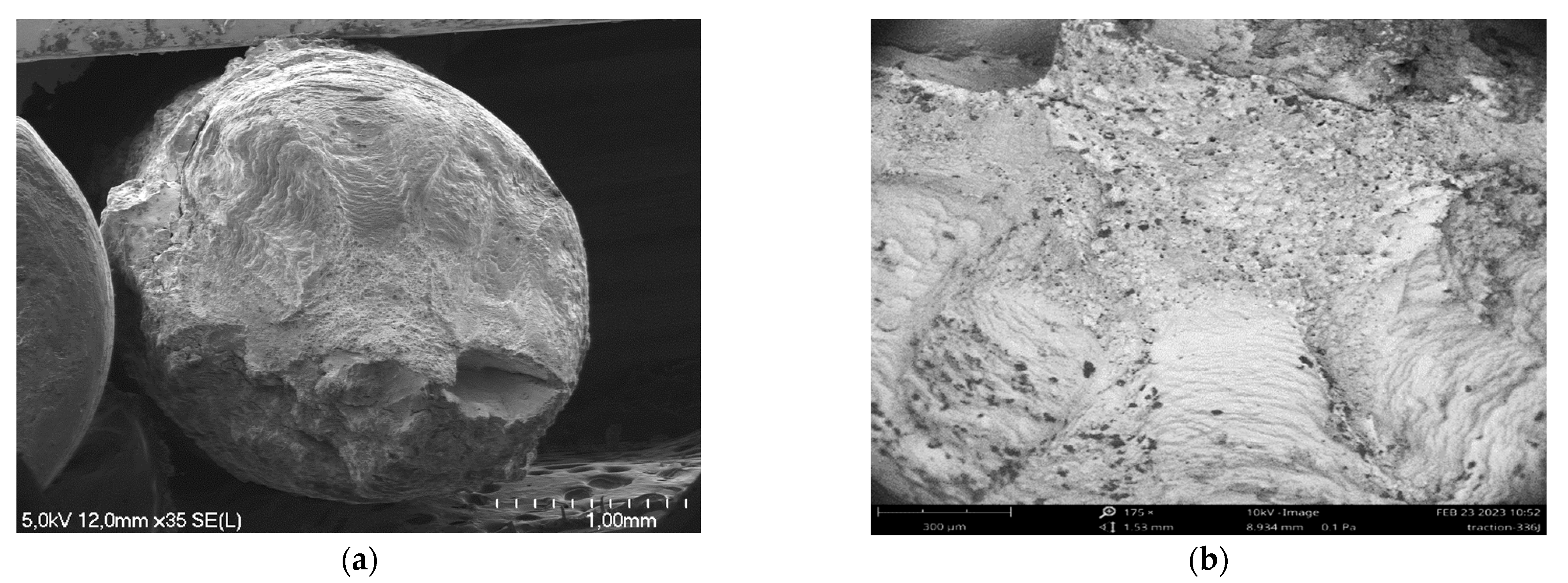
Localized defects such as pits created on the surface of aluminum wires act as crack initiation sites during mechanical testing. Observations of fracture surfaces after tensile test by optical microscopy and SEM confirm the mechanical behavior of the aluminum wires. Thus, for a wire from the internal layer of a greased strand exposed to 42 days of corrosion, the fracture is completely ductile (cup and cone type aspect) with significant necking and numerous dimples on the fracture surfaces (
Figure 11).
This type of ductile mechanical behavior was determined by Lequien et al. on aluminum wires from a greased ASCR conductor in service for 60 years [
35]. The mechanical properties obtained after tensile tests (UTS, elongation) and the fracture surfaces (significant necking presence of dimples) are similar between both studies, highlighting the influence of the grease on the durability of the wires.
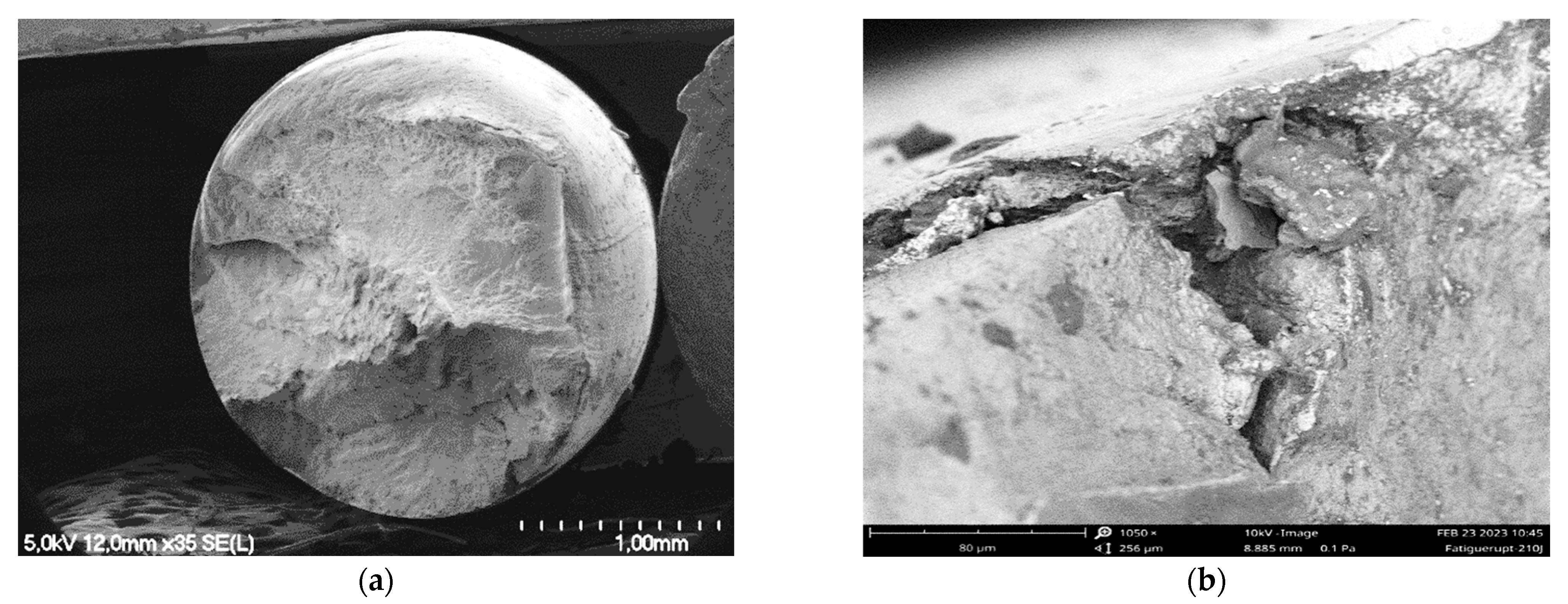
The fracture surface of a wire from the inner layer of an ungreased strand corroded for 336 days is significantly different. It has a semi-fragile appearance with the presence of numerous cleavage-like areas (
Figure 12).
5.2. Fatigue Test Results
The fatigue tests were carried out only on the aluminum wires coming from the ACSR strands. The results obtained are presented in
Figure 13. These are the mean number of cycles for each condition. Usually, three tests were performed for each condition. The fatigue test was interrupted at 5 million cycles without failure of the wire for several cases as-received and after 84 days of accelerated corrosion. Individual results can be found in [
27].
Despite a large dispersion of the results, a reduction in the number of cycles to failure for wires from ungreased strands is observed. This behavior appears for the longest duration in corrosion (336 days). Grease protects wires from corrosion, as highlighted previously in the article. The inner layer wires have a lower number of cycles to failure than those in the external layer for both greased and ungreased strands. The ungreased wires of the inner layer that are in direct contact with the steel wires are more damaged than the wires of the external layer (
Figure 4 and
Figure 5), even though the latter are directly exposed to pollutants. These internal wires are subject to an additional corrosion mechanism, galvanic corrosion. This is due to the loss of the galvanizing layer and direct contact between aluminum and steel wire [
29].
In order to study the influence of the test duration on the evolution of the fracture surface, two durations of 42 days and 336 days of exposure for wires from the internal layer of an ungreased strand were chosen. They represent low and high corrosion damage. These two wires fail at 3.80 × 10
5 cycles and 1.26 × 10
4 cycles, respectively. The appearance of the fracture surface at 42 days is characterized by ductile initiation and propagation phases until failure with the presence of dimples (
Figure 14).
At 336 days, the fracture surface presents a more irregular surface and a reduction in necking, highlighting the loss of ductility in association with corrosion (
Figure 15). Large cleavage-like zones are also present at the surface. According to these results, the lifetime of fatigue of aluminum wires changes depending on the presence of grease and the location of the wires between internal/external layers.
5.3. Torsion Test
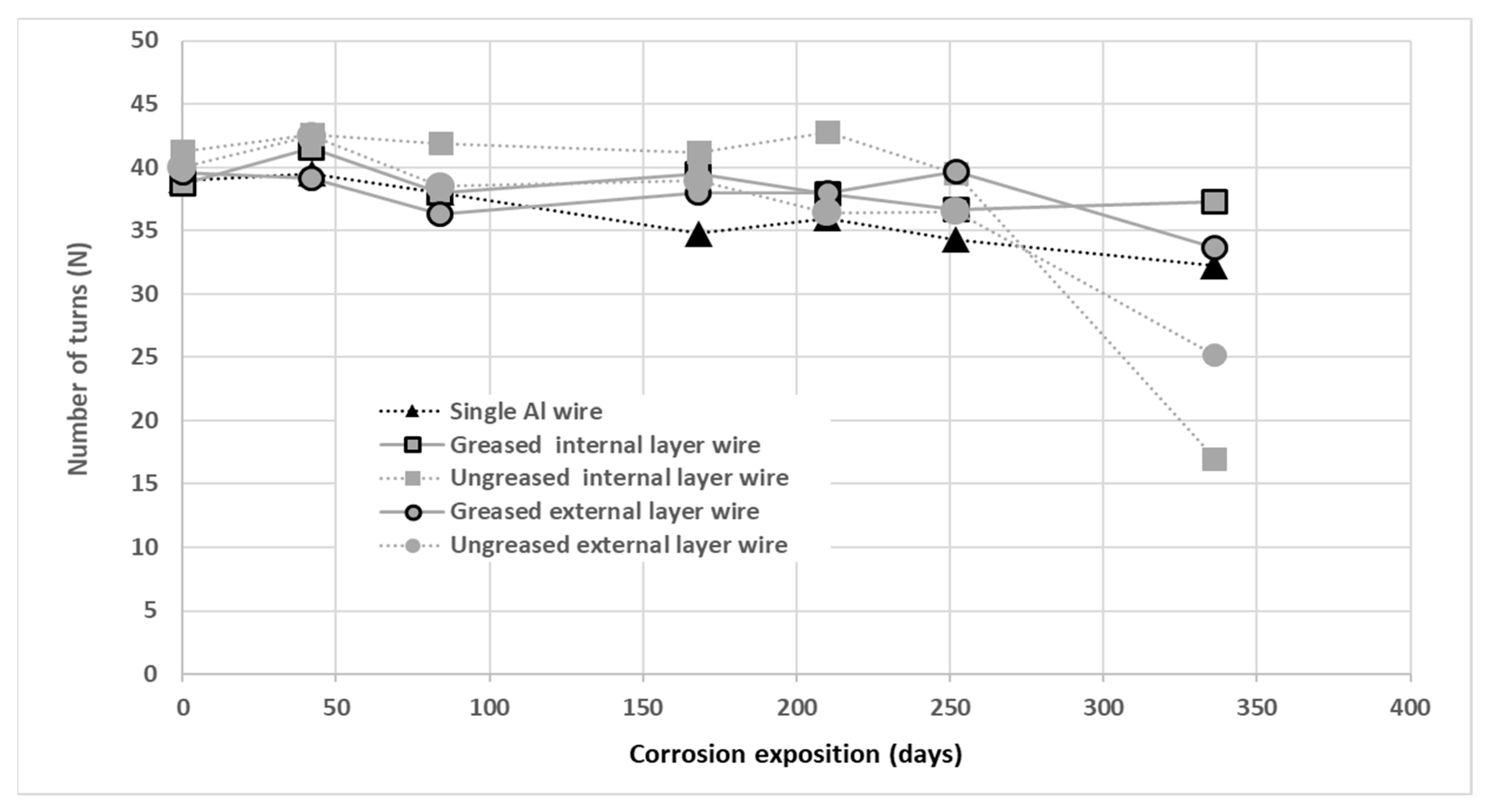
Torsion tests were performed on wires from both greased and ungreased strands and on single wires. Havard et al. evaluated this test as relevant in the characterization of damage and ductility of steel and aluminum wires of ACSR conductors [
36]. The results of the torsion tests are presented in
Figure 16. These are the mean number of turns to reach failure on wires tested for each condition.
The results denote a reduction in the number of turns to failure for wires from ungreased strands at 336 days compared to greased wires and single wires. This signifies a reduction in the ductility of the ungreased wires, particularly the internal layer of wires. The galvanic corrosion mechanism within the strand could explain this behavior. The mechanical torsion tests lead to the same conclusions as those of tension and fatigue, although this torsion test investigates more the ductility of the test specimens. This provides further confirmation of the parameters governing the mechanical life of aluminum wires.
6. Conclusions
In this article, the atmospheric corrosion of aluminum wires from ACSR conductors was studied using accelerated corrosion tests. A salt spray corrosion test was selected. Several durations were chosen in order to observe the evolution of the corrosion damage of the wires. For the longer exposition durations, significant changes in the microstructure and mechanical behavior can be noticed for wires extracted from non-greased ACSR strands. After exposition to corrosion, these wires exhibit pitting and galvanic corrosion, the latter originating from contacts at steel–aluminum interfaces. Corrosion products that are identified at the surface of wires are Al2O3 and Al(OH)3 with chlorine species as AlCl4− and Al2Cl7−. The influence of corrosion on mechanical characteristics is established by a decrease in ductility, maximum elongation, and tensile strength for the longest exposition (336 days). This significant reduction in the internal layer of ungreased wires confirms the importance of the galvanic corrosion mechanism of aluminum wires. This evolution concerns only aluminum wires of non-greased conductors. For single wires or for wires from a greased ACSR strand layer, the mechanical characteristics do not change compared to received wires. The crucial role of grease as protection against corrosion is demonstrated in this study. It prevents different forms of corrosion from developing or at least significantly delays them. The question of greasing after a certain service life is very interesting from a scientific point of view and can be relevant in the case of a life extension depending on the operational impacts of such greasing operations on power lines. Further accelerated corrosion tests and observations on aged conductors from overhead transmission lines are needed to develop a predictive model of corrosion aging and loss of mechanical properties for conductors subject to different environments.
Author Contributions
Conceptualization, L.G., L.D. and S.L.; methodology, A.R. and S.L.; validation, L.G., M.D. and S.L.; formal analysis, M.D. and A.R.; investigation, A.R. and M.D.; resources, M.D. and S.L.; writing—original draft preparation, L.G.; writing—review and editing, S.L. and M.D.; visualization, A.R., L.G. and M.D.; supervision L.G. and S.L.; project administration, L.D. All authors have read and agreed to the published version of the manuscript.
Funding
This research was funded by LIA ECOMAT Université Gustave Eiffel-Université de Sherbrooke, Hydro-Québec, RTE (France), NSERC (Canada) and InnovÉÉ (Québec).
Data Availability Statement
Data are contained within the article.
Acknowledgments
The authors and co-authors would like to acknowledge RTE and SolidAl for providing cables and wires used in this study. The authors sincerely thank J. Creus from LASIE laboratory of the University of La Rochelle for providing the access to RAMAN microscopy. The authors and co-authors would like to acknowledge Sahar Zouari from SMC laboratory of the University Gustave Eiffel for helping on the EDS observations, and the technicians of University of Sherbrooke and University Gustave Eiffel for their help, and expertise.
Conflicts of Interest
The authors declare no conflicts of interest.
References
- Short, T.A. Electric Power Distribution Handbook; CRC Press: Boca Raton, FL, USA, 2004. [Google Scholar]
- Kenge, A.V.; Dusane, S.V.; Sarkar, J. Statistical Analysis & Comparison of HTLS conductor with Conventional ACSR Conductor. In Proceedings of the International Conference on Electrical, Electronics, and Optimization Techniques (ICEEOT), Chennai, India, 3–5 March 2016. [Google Scholar]
- Grigsby, L.L. Electric Power Generation, Transmission, and Distribution, 1st ed.; CRC Press: Boca Raton, FL, USA, 2007. [Google Scholar]
- Isozaki, M.; Adachi, K.; Hita, T.; Asano, Y. Study of corrosion resistance improvement by metallic coating for overhead transmission line conductor. Electr. Eng. Jpn. 2008, 163, 41–47. [Google Scholar] [CrossRef]
- The Aluminum Association. Aluminum Electrical Conductor Handbook, 3rd ed.; Larry Kirkpatrick Editor: Washington, DC, USA, 1989. [Google Scholar]
- Kreislova, K.; Jaglova, M.; Turek, L.; Koukalova, A. Evaluation of corrosion of long-term exposed aluminium conductor. KOM Corros. Mater. Prot. J. 2013, 57, 25–34. [Google Scholar]
- Zhou, Z.R.; Goudreau, S.; Fiset, M.; Cardou, A. Single wire fretting fatigue tests for electrical conductor bending fatigue evaluation. Wear 1995, 181, 537–543. [Google Scholar] [CrossRef]
- Azevedo, C.R.F.; Cescon, T. Failure analysis of aluminum cable steel reinforced (ACSR) conductor of the transmission line crossing the Paraná River. Eng. Fail. Anal. 2002, 9, 645–664. [Google Scholar] [CrossRef]
- Omrani, A.; Langlois, S.; Van Dyke, P.; Lalonde, S.; Karganroudi, S.S.; Dieng, L. Fretting fatigue life assessment of overhead conductors using a clamp/conductor numerical model and biaxial fretting fatigue tests on individual wires. Fatigue Fract. Eng. Mater. Struct. 2021, 44, 1498–1514. [Google Scholar] [CrossRef]
- Zhou, Z.R.; Cardou, A.; Fiset, M.; Goudreau, S. Fretting fatigue in electrical transmission lines. Wear 1994, 173, 179–188. [Google Scholar] [CrossRef]
- Garcia, M.A.; Veloso, L.A.M.; Castro, F.C.; Araujo, J.A.; Ferreira, J.L.A.; Silva, C.R.M. Experimental device for fretting fatigue tests in 6201 aluminum alloy wires from overhead conductors. Wear 2020, 460, 203448. [Google Scholar] [CrossRef]
- Rocha, P.H.C.; Langlois, S.; Lalonde, S.; Araújo, J.A.; Castro, F.C. Influence of 1350 and 6201 aluminum alloys on the fatigue life of overhead conductors–A finite element analysis. Tribol. Int. 2023, 186, 108661. [Google Scholar] [CrossRef]
- Said, J.; Fouvry, S.; Cailletaud, G.; Yang, C.; Hafid, F. Shear driven crack arrest investigation under compressive state: Prediction of fretting fatigue failure of aluminium strands. Int. J. Fatigue 2020, 136, 105589. [Google Scholar] [CrossRef]
- Forrest, J.S.; Ward, J.M. Service experience of the effect of corrosion on steel-cored-aluminium overhead-line conductors. Proc. IEE Part II Power Eng. 1954, 1954, 271–283. [Google Scholar]
- Vera, R.; Delgado, D.; Rosales, B.M. Effect of atmospheric pollutants on the corrosion of high power electrical conductors: Part 1. Aluminium and AA6201 alloy. Corros. Sci. 2006, 48, 2882–2900. [Google Scholar] [CrossRef]
- Elshawesh, F.; Agaili, M.E.L.; Elwaer, A. Atmospheric corrosion of aluminium conductor. Br. Corros. J. 1997, 32, 77–80. [Google Scholar] [CrossRef]
- De Araujo, M.M.; Manheimmer, W.A.; Serra, E.T. Corrosion aspects in aluminum electrical conductors. Corros. Rev. 1988, 8, 175–198. [Google Scholar] [CrossRef]
- Zheng, W.; Li, X.; Xu, Z.; Jin, Z.; Liu, Y. Research on Corrosion Mechanism of Overhead Conductor. In E3S Web of Conferences; EDP Sciences: Les Ulis, France, 2021; Volume 233, p. 01085. [Google Scholar]
- Nawawi, M.I.; Rahman, S.A.; Baharom, M.F. Review on Corrosion Development and Studies on Overhead Line Conductors. Semarak Proc. Appl. Sci. Eng. Technol. 2025, 1, 17–24. [Google Scholar] [CrossRef]
- Vargel, C. Corrosion of Aluminium, 1st ed.; Elsevier Science: Oxford, UK, 2004; p. 700. [Google Scholar]
- Elola, A.S.; Otero, T.F.; Porro, A. Evolution of the pitting of aluminum exposed to the atmosphere. Corrosion 1922, 48, 854–863. [Google Scholar] [CrossRef]
- Kim, S.-D.; Morcos, M.M. Mechanical deterioration of ACSR conductors due to forest fires. IEEE Trans. Power Deliv. 2003, 18, 271–276. [Google Scholar] [CrossRef]
- De la Fuente, D.; Otero-Huerta, E.; Morcillo, M. Studies of long-term weathering of aluminium in the atmosphere. Corros. Sci. 2007, 49, 3134–3148. [Google Scholar] [CrossRef]
- Greenfield, E.W.; Everhart, E.W. A field study ACSR of cable in severe marine and industrial environment. Trans. Am. Inst. Electr. Engineers. Part III Power Appar. Syst. 1957, 76, 106–117. [Google Scholar] [CrossRef]
- ISO 16701:2015; Corrosion in Artificial Atmosphere-Accelerated Corrosion Test Involving Exposure Under Controlled Conditions of Humidity Cycling and Intermittent Spraying of a Salt Solution. 2nd ed. International Organization for Standardization: Geneva, Switzerland, 2015; p. 13.
- ISO 9227:2017; Corrosion Tests in Artificial Atmospheres-Salt Spray Tests. 4th ed. International Organization for Standardization: Geneva, Switzerland, 2017; p. 19.
- Rondineau, A. Essais de Corrosion Accélérée et Évaluation de L’endommagement sur des Conducteurs Aluminium-Acier de Transport D’énergie Électrique. Ph.D. Thesis, Université Gustave Eiffel, France-Université de Sherbrooke, Sherbrooke, QC, Canada, 2023. [Google Scholar]
- ISO 7800:2012; Metallic Materials-Wire-Simple Torsion Test. 3rd ed. International Organization for Standardization: Geneva, Switzerland, 2012; p. 6.
- Rondineau, A.; Gaillet, L.; Dieng, L.; Langlois, S. Degradation of Steel Wires in Bimetallic Aluminum–Steel Conductors Exposed to Severe Corrosion Conditions. Corros. Mater. Degrad. 2022, 3, 646–660. [Google Scholar] [CrossRef]
- Ito, I.; Chiba, H.; Onodera, M.; Fujii, K.; Miyazaki, K. Corrosion Characteristics Based on an Investigation of Sampled OHTL Conductors and a Probabilistic Lifetime Estimation Method. In Proceedings of the 44th CIGRE Session, Paris, France, 26–31 August 2012. [Google Scholar]
- Graedel, T.E. Corrosion mechanisms for aluminum exposed to the atmosphere. J. Electrochem. Soc. 1989, 136, 204C. [Google Scholar] [CrossRef]
- Peng, C.; Liu, Y.-W.; Guo, M.-X.; Gu, T.-Z.; Wang, C.; Wang, Z.-Y.; Sun, C. Corrosion and pitting behavior of pure aluminum 1060 exposed to Nansha Islands tropical marine atmosphere. Trans. Nonferrous Met. Soc. China 2022, 32, 448–460. [Google Scholar] [CrossRef]
- McCaferty, E. Sequence of steps in the pitting of aluminum by chloride ions. Corros. Sci. 2003, 45, 1421–1438. [Google Scholar] [CrossRef]
- Mazhar, A.A.; Arab, S.T.; Noor, E.A. The role of chloride ions and pH in the corrosion and pitting of Al-Si alloys. J. Appl. Electrochem. 2001, 31, 1131–1140. [Google Scholar] [CrossRef]
- Lequien, F.; Auzoux, Q.; Moine, G.; Rousseau, M.; Pasquier-Tilliette, S.; Holande, A.; Ammi, S.; Heurtault, S.; Prieur, P. Characterization of an aluminum conductor steel reinforced (ACSR) after 60 years of operation. Eng. Fail. Anal. 2021, 120, 105039. [Google Scholar] [CrossRef]
- Havard, D.G.; Bellamy, G.; Buchan, P.G.; Ewing, H.A.; Horrocks, D.J.; Krishnasamy, S.G.; Motlis, J.; Yoshiki-Gravelsins, K.S. Aged ACSR conductors Part I: Testing procedures for conductors and line items. IEEE Trans. Power Deliv. 1992, 7, 581–587. [Google Scholar] [CrossRef]
Figure 1.
Test specimens (strands, wires) for corrosion.
Figure 1.
Test specimens (strands, wires) for corrosion.
Figure 2.
Variation in relative humidity during a global cycle (cycle A and 6 cycles B) lasting 84 h.
Figure 2.
Variation in relative humidity during a global cycle (cycle A and 6 cycles B) lasting 84 h.
Figure 3.
Cross-sections of single wires: (a) as-received, (b) 252 days and (c) 336 days.
Figure 3.
Cross-sections of single wires: (a) as-received, (b) 252 days and (c) 336 days.
Figure 4.
Cross-sections of wires extracted from external layer of an ungreased strand: (a) as-received, (b) 252 days and (c) 336 days.
Figure 4.
Cross-sections of wires extracted from external layer of an ungreased strand: (a) as-received, (b) 252 days and (c) 336 days.
Figure 5.
Cross-sections of wires extracted from internal layer of an ungreased strand: (a) 168 days, (b) 252 days and (c) 336 days.
Figure 5.
Cross-sections of wires extracted from internal layer of an ungreased strand: (a) 168 days, (b) 252 days and (c) 336 days.
Figure 6.
Absence of corrosion on aluminum wire cross-sections at 336 days: (a) external layer; (b) internal layer.
Figure 6.
Absence of corrosion on aluminum wire cross-sections at 336 days: (a) external layer; (b) internal layer.
Figure 7.
EDS cartography of a 210 days corroded aluminum wire: (a) SEM; (b) aluminum; (c) oxygen; (d) chlorine.
Figure 7.
EDS cartography of a 210 days corroded aluminum wire: (a) SEM; (b) aluminum; (c) oxygen; (d) chlorine.
Figure 8.
RAMAN spectra of an aluminum wire corroded during 210 days (2.5 and 5 mV).
Figure 8.
RAMAN spectra of an aluminum wire corroded during 210 days (2.5 and 5 mV).
Figure 9.
Ultimate tensile strength (mean value) according to test duration in corrosion for single wires or extracted from greased/ungreased strands.
Figure 9.
Ultimate tensile strength (mean value) according to test duration in corrosion for single wires or extracted from greased/ungreased strands.
Figure 10.
Tensile test curves obtained on aluminum single wires or extracted from greased and ungreased strands after a corrosion test of 336 days.
Figure 10.
Tensile test curves obtained on aluminum single wires or extracted from greased and ungreased strands after a corrosion test of 336 days.
Figure 11.
Fracture surface of a wire from the internal layer of a greased strand and exposed to corrosion for 42 days: (a) full section cup and cone type aspect; (b) presence of numerous dimples located in the central zone.
Figure 11.
Fracture surface of a wire from the internal layer of a greased strand and exposed to corrosion for 42 days: (a) full section cup and cone type aspect; (b) presence of numerous dimples located in the central zone.
Figure 12.
Fracture surface of a wire from the internal layer of an ungreased strand and exposed to corrosion for 336 days: (a) semi-fragile appearance; (b) cleavage-like aspect of the surface.
Figure 12.
Fracture surface of a wire from the internal layer of an ungreased strand and exposed to corrosion for 336 days: (a) semi-fragile appearance; (b) cleavage-like aspect of the surface.
Figure 13.
Fatigue lifetime according to test duration in corrosion for single wires or extracted from greased/ungreased strands.
Figure 13.
Fatigue lifetime according to test duration in corrosion for single wires or extracted from greased/ungreased strands.
Figure 14.
Fracture surface of a wire from the internal layer of an ungreased strand exposed to corrosion for 42 days: (a) initiation of necking; (b) presence of numerous dimples located in the initiation zone.
Figure 14.
Fracture surface of a wire from the internal layer of an ungreased strand exposed to corrosion for 42 days: (a) initiation of necking; (b) presence of numerous dimples located in the initiation zone.
Figure 15.
Fracture surface of a wire from the internal layer of an ungreased strand and exposed to corrosion for 336 days. (a) Quasi absence of necking; (b) cleavage-like aspect at the initiation zone.
Figure 15.
Fracture surface of a wire from the internal layer of an ungreased strand and exposed to corrosion for 336 days. (a) Quasi absence of necking; (b) cleavage-like aspect at the initiation zone.
Figure 16.
Number of turns to failure according to test duration in corrosion for single wires or extracted from greased/ungreased strands.
Figure 16.
Number of turns to failure according to test duration in corrosion for single wires or extracted from greased/ungreased strands.
Table 1.
Chemical composition of aluminum wires (wt%).
Table 1.
Chemical composition of aluminum wires (wt%).
| Al | Fe | Si | Va | Na | Other |
|---|
| 99.9123 | 0.0394 | 0.0267 | 0.0089 | 0.0034 | 0.0093 |
| Disclaimer/Publisher’s Note: The statements, opinions and data contained in all publications are solely those of the individual author(s) and contributor(s) and not of MDPI and/or the editor(s). MDPI and/or the editor(s) disclaim responsibility for any injury to people or property resulting from any ideas, methods, instructions or products referred to in the content. |
© 2025 by the authors. Licensee MDPI, Basel, Switzerland. This article is an open access article distributed under the terms and conditions of the Creative Commons Attribution (CC BY) license (https://creativecommons.org/licenses/by/4.0/).


