Article

Chemical Equilibrium Fracture Mechanics—Hydrogen Embrittlement Application

by
Andreas G. Varias
Euro Harmonization and Engineering, Makedonias 17, N. Iraklio 14121, Greece
Corros. Mater. Degrad. 2025, 6(1), 5; https://doi.org/10.3390/cmd6010005
Submission received: 12 January 2025 / Revised: 26 January 2025 / Accepted: 30 January 2025 / Published: 6 February 2025
(This article belongs to the Special Issue Hydrogen Embrittlement of Modern Alloys in Advanced Applications)

Abstract

:
Chemical Equilibrium Fracture Mechanics (CEFM) studies the effect of chemical reactions and phase transformations on crack-tip fields and material fracture toughness under chemical equilibrium. An important CEFM direction is hydrogen-induced embrittlement of alloys, due to several industrial applications, including those within the industrial value chain of hydrogen that is under development, which, according to European and international policies, are expected to contribute significantly to the replacement of fossil fuels by renewable energy sources. In the present study, the effect of hydrogen on the crack-tip fields of hydride- and non-hydride-forming alloys is examined. The crack-tip stress and hydrogen concentration distributions are derived under hydrogen chemical equilibrium, which is approached by considering the coupling of the operating physical mechanisms. In all cases, analytic relations are derived, thus facilitating integrity assessments, i.e., without the need to rely on complicated numerical methods, expected to lead to the development of respective tools in industrial applications. It is shown that, in the case of hydride precipitation, there are significant deviations from the K, HRR, and Prandtl fields, and, thus, the well-known approaches of Linear Elastic Fracture Mechanics (LEFM) and Elastic–Plastic Fracture Mechanics (EPFM) need to be accordingly modified/extended.

1. Introduction

Anthropogenic greenhouse gas emissions, generated following the Industrial Revolution, with a continuous steep increase in the 20th century, are related to global warming and associated with climate/environment phenomena that introduce significant risks, beyond prosperity, on human life and activities (e.g., [1]). In an effort to contain the increase in the global mean surface temperature, governments around the world have introduced several measures with the objective of net-zero greenhouse gas emissions by 2050. The most important part of greenhouse gas emissions is related to energy consumption in industry, transportation, and buildings, and is associated with fossil fuels. Thus, the net-zero greenhouse gas emission target is strongly related to the replacement of fossil fuels. Hydrogen is expected to contribute to achieving the net-zero target by introducing a storage medium for the efficient generation of electricity from renewable energy sources as well as an alternative fuel or fuel-carrier both in energy generation and transport. Furthermore, hydrogen is expected to contribute to the development of new technologies, beyond the needs related to climate change, such as in applications in the superconductivity, aviation, and automotive industries (e.g., [2]).
Closely related to the industrial value chain of hydrogen are material compatibility issues. Indeed, hydrogen diffuses easily in metallic structures due to its size, and may lead to embrittlement, a severe type of material degradation that can cause failure under very low loads, compared to those carried by a hydrogen-free material. Extensive studies have been performed and several mechanisms have been proposed to explain hydrogen-induced embrittlement and subcritical crack growth (e.g., [3,4]).
In the case of the formation of hydrides, in metals such as titanium, zirconium, magnesium, vanadium, and niobium, the embrittlement mechanism is well understood (e.g., [5,6,7,8]). In this case, material deterioration is caused when the hydrogen content exceeds its terminal solid solubility through the precipitation of the hydride brittle phase. Then, if the load applied on the structure exceeds a threshold, delayed hydride cracking occurs and a crack propagates in a discontinuous fashion; a complete crack growth cycle includes the stress-directed diffusion of hydrogen towards the crack tip, hydride precipitation, and fracture. Several finite element studies have been performed on hydride precipitation and related material degradation (e.g., [9,10,11,12,13,14,15,16,17,18,19,20,21]). Interesting contributions, approaching environmental conditions encountered in the industry, take into account the coupling of the operating physical processes of hydrogen diffusion, non-mechanical energy flow, hydride precipitation, material deformation, and fracture (e.g., [12,20]). Of equal interest are the analytically derived crack-tip fields, under hydrogen chemical equilibrium, which are characterized by significant deviations from those considered in Linear Elastic and Elastic–Plastic Fracture Mechanics [22,23,24]. These are issues important to the aerospace, automotive, nuclear, and additive manufacturing industry, where alloys of Ti, Mg, and Zr are used (e.g., [25,26,27]).
In the case of hydrogen embrittlement without the formation of hydrides, as in iron, nickel, aluminum (in some cases in titanium too (e.g., [8,28]), the physical process is still under investigation. In this case, hydrogen-enhanced decohesion (HEDE), hydrogen-enhanced localized plasticity (HELP), and adsorption-induced localized slip are the main mechanisms that have been proposed to explain material deterioration; the combined operation of these mechanisms has also been discussed (e.g., [29,30]). According to HEDE, hydrogen leads to a reduction in the cohesive strength of the lattice and promotes cleavage (e.g., [31,32,33,34]). HEDE has been considered in interfacial fractures as well (e.g., [35]). The decohesion mechanism is supported by theoretical calculations of the effect of hydrogen on atomic potentials and also by thermodynamic arguments. The HELP mechanism (e.g., [36,37,38]) suggests that hydrogen alters the plastic deformation behavior of the material. Indeed, in situ environmental cell transmission electron microscopy studies have shown an increase in the dislocation mobility in the presence of hydrogen (e.g., [39]). According to adsorption-induced localized slip, hydrogen causes weakening of the interatomic bonds, as in the case of HEDE, but crack growth occurs by hydrogen-induced slip localization, as in the case of the HELP mechanism [40]; based on this mechanism, adsorbed hydrogen or hydrogen in the first and second atomic layers of a crack tip weakens the substrate interatomic bonds and thereby facilitates the emission of dislocations from the tip. In view of the complexity of hydrogen’s effects on deformation and fracture, no firm conclusions about the mechanisms of hydrogen-related fracture can yet be reached for metals that do not exhibit hydride formation. However, significant progress can be made on a very important aspect of hydrogen embrittlement: the transport of hydrogen to the sites where material degradation occurs. Thus, significant efforts have dealt with the development of FEM models, which take into account the coupling of the operating mechanism (e.g., [41,42,43,44,45,46,47,48]). Certainly, the current and expected industrial use of non-hydride-forming alloys in a hydrogen environment (e.g., [2]) promotes further developments.
Chemical Equilibrium Fracture Mechanics (CEFM) can be applied to both hydride and non-hydride-forming alloys, under conditions leading to hydrogen-induced material deterioration. The objective of CEFM is the prediction of material fractures by combining input from thermodynamics, materials science, solid mechanics, and mathematics, as shown in Figure 1. The basic assumption of CEFM is that any physical mechanism, which leads to material deterioration, operates under chemical equilibrium. In the case of hydrogen-induced embrittlement, this assumption corresponds to zero hydrogen flux. Then, material deterioration is examined following hydrogen redistribution, which leads to hydrogen concentration spatial distribution independent of time. It is noted that an implication of the assumption on hydrogen flux is also the establishment of steady-state heat conduction, i.e., of time-independent temperature spatial distribution. In industrial applications, this assumption corresponds to steady-state facility operation. Although transients are not considered, a steady state provides the basic conditions of the initial design related to the material selection and main dimensions, given the range of operation parameters.
The initial studies, based on CEFM, were applied to hydrogen embrittlement of non-hydride- [49], and hydride-forming metals [22,23,24]. An interesting feature of the previously mentioned studies is their analytical development; the predicted analytical results are in agreement with chemical equilibrium predictions of detailed FEM transient models, which take into account the coupling of the operating physical mechanisms. Thus, based on CEFM, user-friendly tools of adequate accuracy could be developed. Another very important CEFM outcome is the crack-tip stress field, which deviates significantly from the well-known Linear Elastic and Elastic–Plastic Fracture Mechanics (LEFM, EPFM) crack-tip fields, when hydrides precipitate. The structure of the CEFM crack-tip field is clearly presented via analytic relations, which thus enhance the understanding of hydride precipitation implications.
In Section 2, the basis of CEFM in the case of hydrogen embrittlement is presented for both non-hydride- and hydride-forming alloys. In Section 3, predictions of hydrogen concentration and stress distributions ahead of a crack under mode I plane strain conditions and constant temperature are given for steel, nickel, and titanium alloys of importance to industrial applications. Finally, the conclusions are given in Section 4.

2. Materials and Methods

2.1. Areas of Hydrogen in Solid Solution

Material deformation, energy flow, and diffusion of mass are coupled processes. A detailed discussion and relevant references for the thermodynamic treatment of energy flow/mass diffusion as well as of other coupled phenomena are presented by Denbigh [50] and Shewmon [51]. These models were extended to consider the coupling of material deformation, hydrogen diffusion, hydride precipitation, and energy flow under transient crack growth [11,12]. In addition, the coupled processes were taken into account under hydride-induced steady-state crack growth at a constant temperature [13,14]. Important implications of crack-tip stress and hydrogen concentration distributions at the limit of hydrogen chemical equilibrium and steady heat conduction or constant temperature are discussed in [22,23,24,49]. Readers who are interested in the details of the previously mentioned developments are referred to those publications. The basic governing relations of the previous analysis are repeated in this section to introduce model assumptions and major physical parameters. All of the following relations are written with respect to a Cartesian coordinate system ( x 1 ,   x 2 ,   x 3 ); the repetition of indices denotes summation.
In a metal, under hydrogen chemical equilibrium and steady-state heat transfer, hydrogen flux is equal to zero and heat flux is governed by Fourier’s law. Under these conditions, the chemical potential of hydrogen in solid solution, μ H , satisfies the following relation [22]:
μ H + ln T Q H = c o n s t .
or equivalently,
C H V ¯ R T T Q H = Μ   e x p σ m m V ¯ H 3 .
In the above relations, Q H and V ¯ H are the heat of transport and the molal volume of hydrogen in the solid solution, respectively.   C H is the concentration of hydrogen in solid solution at interstitial lattice sites, given in moles per unit volume. Also, V ¯ is the molal volume of the metal, T is the temperature, and R is the gas constant (=8.314 J·mol−1·K−1). Μ is a constant, which depends on thermal–mechanical and environmental loading. The constant Μ is calculated by considering stress trace, hydrogen concentration, and temperature at a reference particle ( σ R e ,   C R e H ,   T R e ). Then, relation (2) is rewritten as follows:
C H C R e H = C R e H V ¯ T R e T 1 T R e T Q H R T e x p σ m m σ R e 3 R T V ¯ H .
It is worth mentioning that, in the case of hydrogen embrittlement experiments or structural integrity evaluations, the proper selection of the position of the reference particle may facilitate measurement interpretation and/or mechanics analysis. For example, in the case of testing a center-cracked panel or a notched bar under tension in a hydrogen atmosphere of specified pressure and temperature, the selection of the reference particle on a specimen surface far from the crack or notch tip allows for the straightforward evaluation of σ R e and C R e H , the second based on Sieverts’ law (e.g., [52]), appropriately modified in order to take into account tensile stress applied on the specimen. Thus, the experimental data could be interpreted by considering the pressure and temperature of the hydrogen atmosphere, the mechanical load applied on the specimen, and the analysis in the present paper. Note that, in order to achieve chemical equilibrium, there is no variation in stress and strain. Thus, at the equilibrium limit under consideration, there is no contribution to hydrogen flux by dislocation transport (e.g., [47]). Under constant temperature and, therefore, in the absence of heat conduction, relation (3) yields the following well-known relation (e.g., [13]):
C H C R e H = e x p σ m m σ R e 3 R T V ¯ H .
When there is no hydride precipitation, hydrogen has a negligible effect on stress trace. Thus, under no hydride formation, given the stress and temperature distributions in a hydrogen-free structure, relation (3) provides the distribution of hydrogen concentration in solid solution at lattice interstitial sites, parametrized by hydrogen concentration, stress trace, and temperature in a reference particle.
Hydrogen atoms, in addition to being accommodated in normal interstitial lattice sites, can be trapped by defects in the lattice, such as voids and dislocations, as well as in grain boundaries and interfaces with second phase particles (e.g., [51,53,54]). Near a crack tip, dislocation traps are important due to the singularity of the plastic strains. However, existing traps due to plastic deformation during manufacturing as well as those due to matrix/precipitate interfaces could also be important. Under the condition of hydrogen chemical equilibrium in the present analysis, there is chemical equilibrium between hydrogen in interstitial sites and traps. Then, the following relation is considered [54], based on Fermi–Dirac statistics (e.g., [52]):
K e q = 1 θ I θ I θ T 1 θ T = exp Δ E T R T ,
C H = θ I N I ,
C T = θ T N T .
K e q is the chemical equilibrium constant of hydrogen in interstitial and trap sites, which depends, exponentially, on trap binding energy, Δ E T ; for information on trap type identification and binding energy derivation, based on thermal desorption analysis, the interested reader is referred to [52]. N I is the number of interstitial sites per unit volume, divided by Avogadro’s number, N A (=6.022 × 10²³ atoms per mol), and θ I is the fraction of occupied interstitial sites. Note that N I is related to the molal volume of the solvent metal, V ¯ , and the number of interstitial sites per solvent atom, β (= N I V ¯ ). C T is the concentration of hydrogen in traps, given in moles per unit volume, N T is the number of trap sites per unit volume (which includes the possibility of several hydrogen atoms trapped at a site), divided by Avogadro’s number, and θ T is the fraction of occupied trap sites. Relation (5) has also been confirmed by detailed transient analysis, according to which a good agreement has been found between Oriani’s equilibrium theory and McNabb–Foster formulation in both trap and lattice site concentrations for sufficiently long loading times [45].
Elaboration of relations (5)–(7) leads to a relation between hydrogen concentration in traps and interstitial sites:
C T = N T 1 + 1 C H / N I K e q C H / N I ,
or equivalently,
C T C H = K e q N T K e q 1 C H + N I .
When the occupancy of interstitial lattice sites is small compared to unity ( θ Ι = C H / N I 1 ) , relation (8) leads to a simplified relation, given in previous publications (e.g., [41,53,55]). According to relations (9) and (4), or (3) under varying temperature, the ratio of the concentration of hydrogen in traps over the concentration of hydrogen in interstitial sites decreases mainly with the increase in average hydrogen content and secondarily with the increase in stress trace; it is taken into account that the reference particle is selected far from a stress concentrator or crack tip, in which case, C R e H approaches the average hydrogen content in the whole body. In addition, an increase in temperature leads to a decrease in C T / C H .
In the case of dislocation traps, the number of trap sites generally depends on accumulated effective plastic strain (e.g., [41,42,56]). Then, relations (3) or (4), under constant temperature, and (8) or (9) provide the distribution of hydrogen concentration in interstitial lattice sites and traps under hydrogen chemical equilibrium in any geometry/structure when temperature, stress, and accumulated effective plastic strain distributions are known. When the number of trap sites saturates at a relatively large value of accumulated effective plastic strain, a constant number of traps can be used, corresponding to the limit at large strains. In this case, a conservative distribution of hydrogen concentration in interstitial sites and dislocation traps is derived without considering plastic strain distribution; this is also the case with a constant number of traps, due to initial plastic deformation of the material during manufacturing or due to the presence of traps on precipitate/matrix interfaces (e.g., [42]).

2.2. Areas of Hydride Precipitation

The previous relations are valid in the areas, where hydrogen is in solid solution. In hydride-forming metals, such as Ti, V, Zr, Mg, and Nb, there are additional relations, which dominate in the zone of hydride precipitation; this zone contains both hydrogen in solid solution and hydrides. Indeed, in the hydride precipitation zone, hydrogen concentration, C H , is equal to hydrogen terminal solid solubility,   C T S , which generally depends on stress trace and temperature [13]:
C T S = C e T S exp w ¯ i n t x R T exp σ m m V ¯ H 3 R T ,
C e T S = C 0 e x p D R T ,
where C e T S is the terminal solid solubility of hydrogen in the metal, under no applied stress, and incorporates the strain energy, which is required for the accommodation of the expanding hydrides; C 0 and D are material constants, which are measured experimentally. x is the mole fraction of hydrogen in the hydride. w ¯ i n t is the interaction energy per mole of precipitating hydride of volume, V ¯ h r , and results from the interaction of the applied stress field, σ i j , with the field of the expanding hydride. If one assumes an elastically isotropic hydride of elastic constants equal to those of the metal, the interaction energy is simplified and becomes equal to w ¯ i n t = σ m m / 3 θ h r V ¯ h r , where θ h r is the hydride expansion strain. Relation (10) is derived by assuming that the phase transformation is a reversible process, which occurs under local chemical equilibrium among the hydride, the metal, and the hydrogen in solid solution. For a detailed discussion, analysis, and the general relation of hydrogen terminal solid solubility in an anisotropic material with different hydride and solid solution properties, one is referred to [13].
Under hydrogen chemical equilibrium in the hydride precipitation zone, relations (3) and (10) are simultaneously valid. Then, the combination of (3) and (10) leads to a general relation of the stress trace in the hydride precipitation zone, σ h z [22]:
σ h z = 3 x θ h r V ¯ h r σ R e V ¯ H 3 + R T   l n C e T S C R e H + R T T R e   l n C R e H V ¯ Q H   l n T R e T .
When the temperature is constant, relation (12) is simplified as follows:
σ h z = 3 x θ h r V ¯ h r σ R e V ¯ H 3 + R T   l n C e T S C R e H .
Relation (13) is also identical to (21), presented in [13]. According to (13), the stress trace in the hydride precipitation zone is constant under constant temperature. σ h z is the result of zero hydrogen flux throughout the solid solution (i.e., of hydrogen chemical equilibrium in solid solution) and chemical equilibrium among hydrogen, metal, and hydride in the hydride precipitation zone. It is also valid for a continuum, which deforms either elastically or elastic–plastically.
In the present analysis, hydrides are assumed to be smeared and characterized by hydride volume fraction f [11,12,13,14,22,23,24], which is related to the stress-free expansion of a material particle ( 1 3 δ i j f θ h r ; δ i j is Kronecker delta; also, hydride expansion is considered dominant, related to the expansion, which is caused by hydrogen in solid solution and, therefore, neglected).
According to the analysis given by Varias [22,23,24], the hydride volume fraction, f , and the stress components in the hydride precipitation zone are given by the following relations:
f 1 2 ν E Z θ h r S m m σ h z ,
σ i j S i j δ i j 3 S m m σ h z ,   S m m σ h z .
The metal is assumed to have Young’s modulus E and Poisson’s ratio ν . S i j   is the stress field in the metal, without the presence of hydrogen, which dominates before the precipitation of the hydrides and the establishment of chemical equilibrium. Z provides the relation between the stress-free ( ε i j H , c e ) and total (constrained by the surrounding matrix, ε i j c e ) hydride-induced expansion at a material particle, ε m m H , c e ε m m c e = Z ε m m H , c e . Z depends on elastic and plastic material properties, as well as on hydride expansion strain, θ h r . In the case of linear elastic material behavior, Z = 1 1 + ν / 3 1 ν [57,58,59]. Under elastic–plastic material behavior, Z takes values, which decrease significantly when the deformation of the material changes from linear elastic to perfectly plastic [59,60]. In relation (14), the expansion of the metal due to hydrogen dissolution has been neglected with respect to the expansion caused by hydride precipitation. In relation (15), S m m σ h z specifies also a hydride precipitation condition. In a particle of a structure, hydride precipitation is only possible if the local stress trace of the hydrogen-free structure, S m m , is larger than the stress trace of the hydride precipitation zone, σ h z , expected to be developed; at equality, the hydride volume fraction equals zero. It is emphasized that, according to (15), the normal stress components are smaller than those dominating before hydride precipitation, reduced by the difference in the hydrostatic stress before and after hydride precipitation. Relation (15) is exact under perfectly plastic material behavior, when slip-line inclination remains the same before and after hydride precipitation [24]. Thus, given the hydrogen concentration in the reference particle, C R e H , the stress trace in the hydride precipitation zone is directly derived based on (12) or (13); it is noted that, in a structure under nearly uniform applied stress, when the reference particle is selected far from a stress concentrator or crack, C R e H tends to the average hydrogen content. Then, in the case of hydrogen chemical equilibrium, the stress distribution in the hydride precipitation zone is directly derived based on (15), given the stress distribution in the hydrogen-free structure, without the need of a complicated FEM analysis (i.e., without the need of an FEM analysis, which takes into account the coupling of hydrogen diffusion, hydride precipitation, material deformation, and energy transfer).
All relations presented in Section 2.1 and Section 2.2 are valid for material deformation, which could be elastic or elastic–plastic for any degree of hardening. These general relations are applied to fracture mechanics in the following section.

3. Results and Discussion

Consider an infinite body with a crack, under plane strain, mode I loading, hydrogen chemical equilibrium, and constant temperature. The body is assumed to be in equilibrium with hydrogen gas of pressure p and temperature T ; the hydrogen gas pressure and temperature are given values that correspond to hydrogen in solid solution far from the crack tip in the case of a hydride-forming alloy. A Cartesian coordinate system ( x 1 ,   x 2 ,   x 3 ) is considered, which has its origin at the crack tip. x 1 lies on the crack plane, normal to the crack edge. x 2 is normal to the crack plane. Also, r , φ ,   x 3 is the respective cylindrical coordinate system, where r is the radial distance from the crack tip and φ is the angle, measured from the crack plane. Furthermore, the reference particle, introduced in relation (3), is positioned far away from the crack edge and faces. Thus, σ R e is, generally, negligible compared to the near-tip stresses.
The metal is generally assumed to deform elastic–plastically, according to power-law hardening (e.g., [61]):
ε ¯ p ε 0 = a σ ¯ σ 0 n ,
where ε ¯ p and σ ¯ are the effective plastic strain and effective stress, respectively; d ε ¯ p = 2 3 d ε i j p d ε i j p 1 2 , σ ¯ = 3 2 σ i j σ i j 1 2 and σ i j = σ i j 1 3 σ m m δ i j . Also, a is a material constant, taken as equal to 0,01 in the present analysis. In the case of the value of a , which is small compared to 1, σ 0 is about equal to the yield stress in tension and ε 0   = σ 0 / Ε , to the respective strain at yielding. n > 1 is the strain hardening exponent; in the limit as n , non-hardening behavior is approached. In the case of hydride precipitation, elastic and perfectly plastic material behaviors are also considered, in order to reveal the effect of hydride precipitation on the crack-tip stress field, within the whole range of material deformation from linear elastic to elastic–plastic with hardening and perfectly plastic behavior.
The properties of steel, X-750 Ni-Cr-Fe alloy, and α-phase titanium used in the following calculations are given in Table 1, Table 2, and Table 3, respectively, together with the source of information.

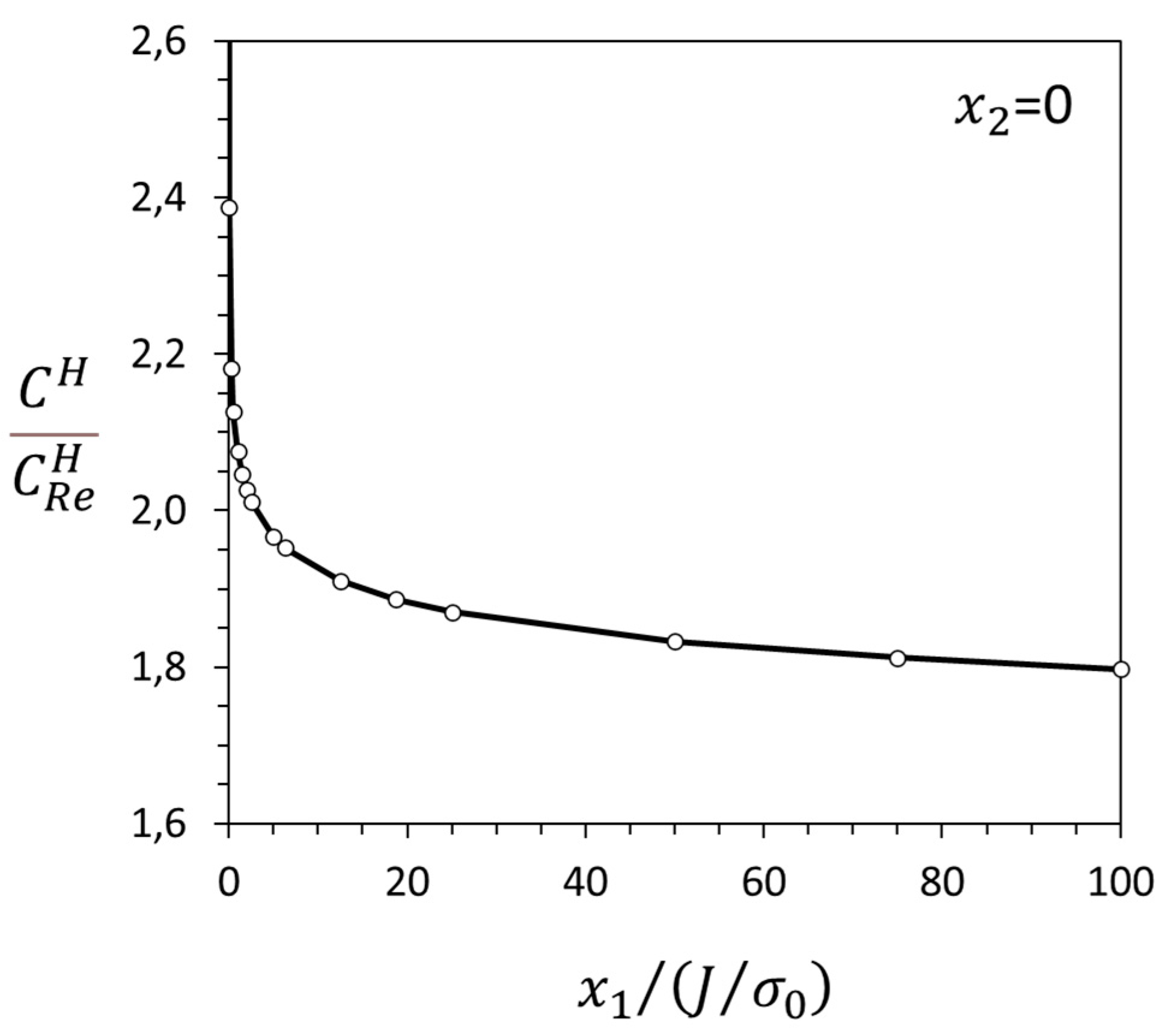
3.1. Crack-Tip Fields for Hydrogen in Solid Solution

Calculations have been performed for a non-hydride-forming alloy, ASTM A 106 Grade B steel at 20 °C, with properties given in Table 1. Elastic–plastic material response is considered with hardening exponent, n , equal to 20. Due to small lattice expansion, introduced by the disolution of hydrogen, the near-tip field is adequately represented by the HRR field [74,75]. Furthermore, in order to quantify the implications of high hydrogen gas pressures, expected in engineering applications, on the distribution of hydrogen in traps and interstitial lattice sites, Sievert’s law is considered:
C R e H = C F e x p H s R T F e x p V ¯ H 3 R T σ R e ,
where F is the fugacity of hydrogen and H S is its heat of solution in the metal. Relation (17) is derived by taking into account the chemical equilibrium between hydrogen gas and hydrogen in solid solution at the reference particle. For iron, C F equals 260.56 mol/m3 (i.e., 0.00185 atom fraction of hydrogen in α-iron lattice) and H S equals 28,600 J/mol, according to [64]; the previous C F -value corresponds to the fugacity in bars. When an Abel–Noble deviation from perfect gas is considered, the fugacity correlates with the hydrogen gas pressure, p , according to relation F = p · e x p B p / R T . B has been calculated equal to 1.584 × 10⁻⁵ m3/mol [76], when p is given in Pa. The calculation of B was based on experimental data for temperature ≥ 223 K and pressure < 200 MPa. In the mentioned ranges, the B values vary by less than 1%. In the present analysis, the value of B is assumed to be valid up to 1000 bar. Then, for hydrogen pressures in the range 1–1000 bar, expected in industrial applications, C R e H varies up to 0.091 mol/m3 for a temperature of 20 °C; the range is calculated by neglecting σ R e . Any deviation on the value of B may only change the actual range of C R e H but not the conclusions of the analysis. Indeed, when considering a perfect gas constitutive law, C R e H takes values up to 0.066 mol/m3 when the hydrogen pressure reaches 1000 bar, which confirms the conclusions on the hydrogen concentration in trap sites, as discussed later on in this section.
The hydrogen concentration in interstitial lattice sites, C H , is calculated by substituting the HRR field stress trace in relation (4); the tables of the HRR field in [77] have been considered. The distribution ahead of the crack tip on the crack plane is presented in Figure 2. As expected, the hydrogen concentration increases significantly as the crack tip is approached due to the respective increase in the stress trace.
Figure 3 shows C H -contour plots on the plane of deformation, normal to the crack edge. The hydrogen concentrates in a sector about equal to 90° ahead of the crack tip, where the stress trace is relatively larger.
The hydrogen concentration in dislocation traps, C T , is calculated by relation (9). The number of trap sites per unit metal volume, N T · N A , is taken as equal to 1023, which is the limiting value, expected after significant plastic deformation [65]; one hydrogen site per trap is assumed. The limiting value is used since the area ahead of the crack, close to the tip, where plastic strains are significant, is the expected area of failure due to hydrogen embrittlement. The trapped hydrogen concentration is affected by the average hydrogen content, approached by C R e H far from the crack tip, and local stress trace. Both effects are presented in Figure 4. The hydrogen concentration in traps is significantly larger, even by two orders of magnitude, than the hydrogen concentration in interstitial lattice sites, for the steel under consideration with a relatively small amount of average hydrogen content, which is expected when the hydrogen gas pressure is up to 50 bar. However, the ratio C T / C H decreases significantly when the average hydrogen content increases. Therefore, as the hydrogen gas pressure increases, the amount of hydrogen in the interstitial lattice sites becomes of equal importance to the hydrogen in dislocation traps in the case of low-yield stress carbon steel. If, instead of a maximum trap density, a relation between the trap density and effective plastic strain is considered, as in Figure 1 of [41], the C T / C H ratio takes smaller values, thus confirming the previous main conclusion.
Calculations have also been performed for a crack in the non-hydride-forming X-750 Ni-Cr-Fe alloy at 25 °C and 285 °C; the material’s properties are given in Table 2. The hydrogen concentration in the interstitial lattice sites, C H , is controlled by the HRR stress trace distribution. Therefore, the C H distribution is similar to the one presented in Figure 2 and Figure 3. The hydrogen concentration in the trap sites, expressed as the   C T / C H ratio, is presented in Figure 5. Hydrogen is considered to be trapped at the interface, between the matrix and γ′ precipitates, with the number of trap sites per unit metal volume, N T · N A , equal to 6 × 1026 [42]. The range of the average/remote hydrogen content, C R e H , is specified, based on X-750 hydrogen embrittlement experimental data [35]. According to Figure 5, the hydrogen concentration in the trap sites ahead of the crack tip is comparable to the hydrogen concentration in the interstitial lattice sites at 25 °C and significantly smaller at 285 °C. The present analytical estimates, based on the hydrogen chemical equilibrium, are in agreement with the transient finite element results corresponding to significant elapsed time, which is characterized by the approach towards the hydrogen chemical equilibrium [42].
The estimates of the hydrogen concentration in traps and interstitial lattice sites, as discussed above, together with the reference experimental measurements for the embrittlement of an alloy form the basis for predicting the deterioration of a structure in a hydrogen environment.

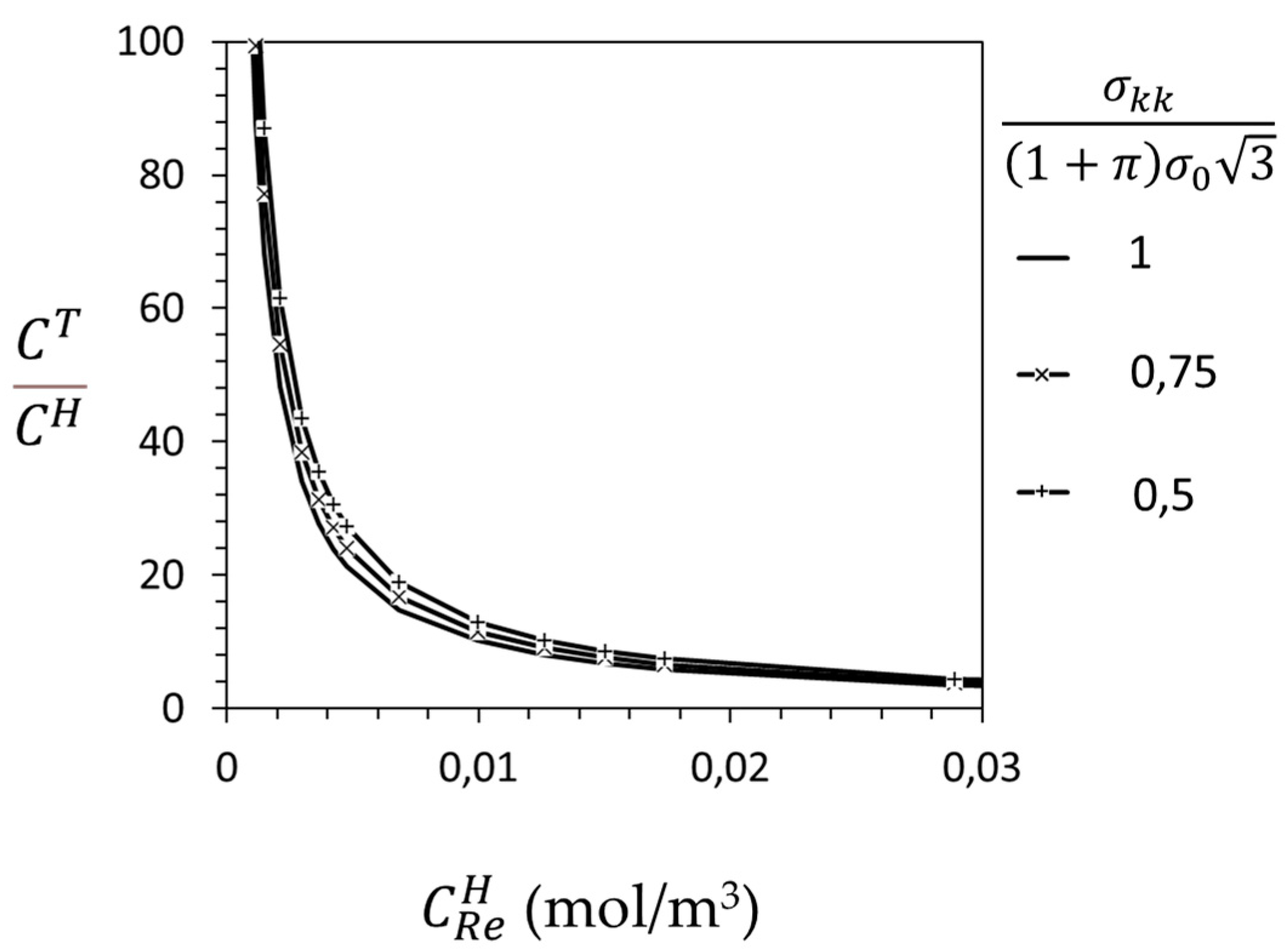
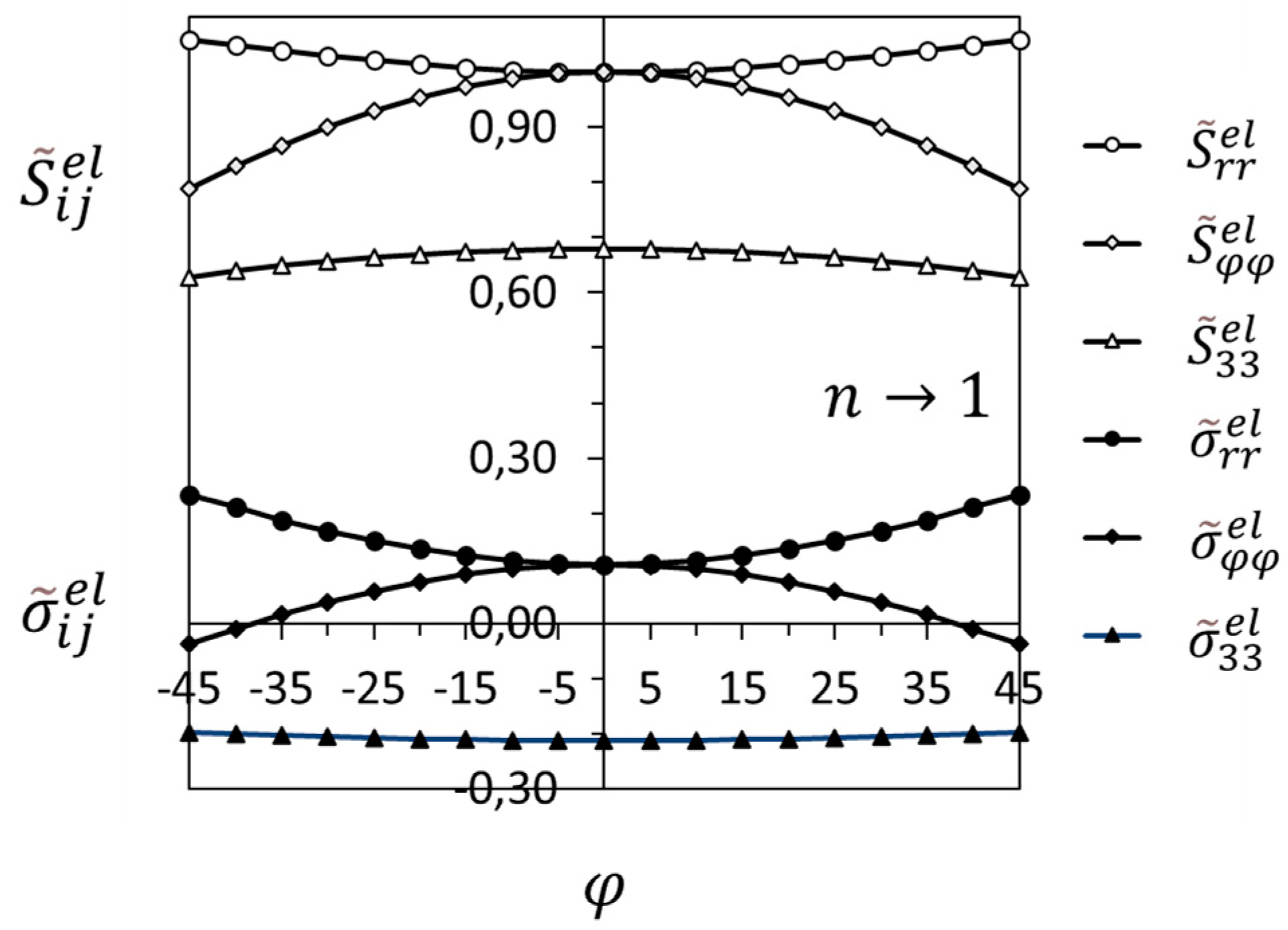
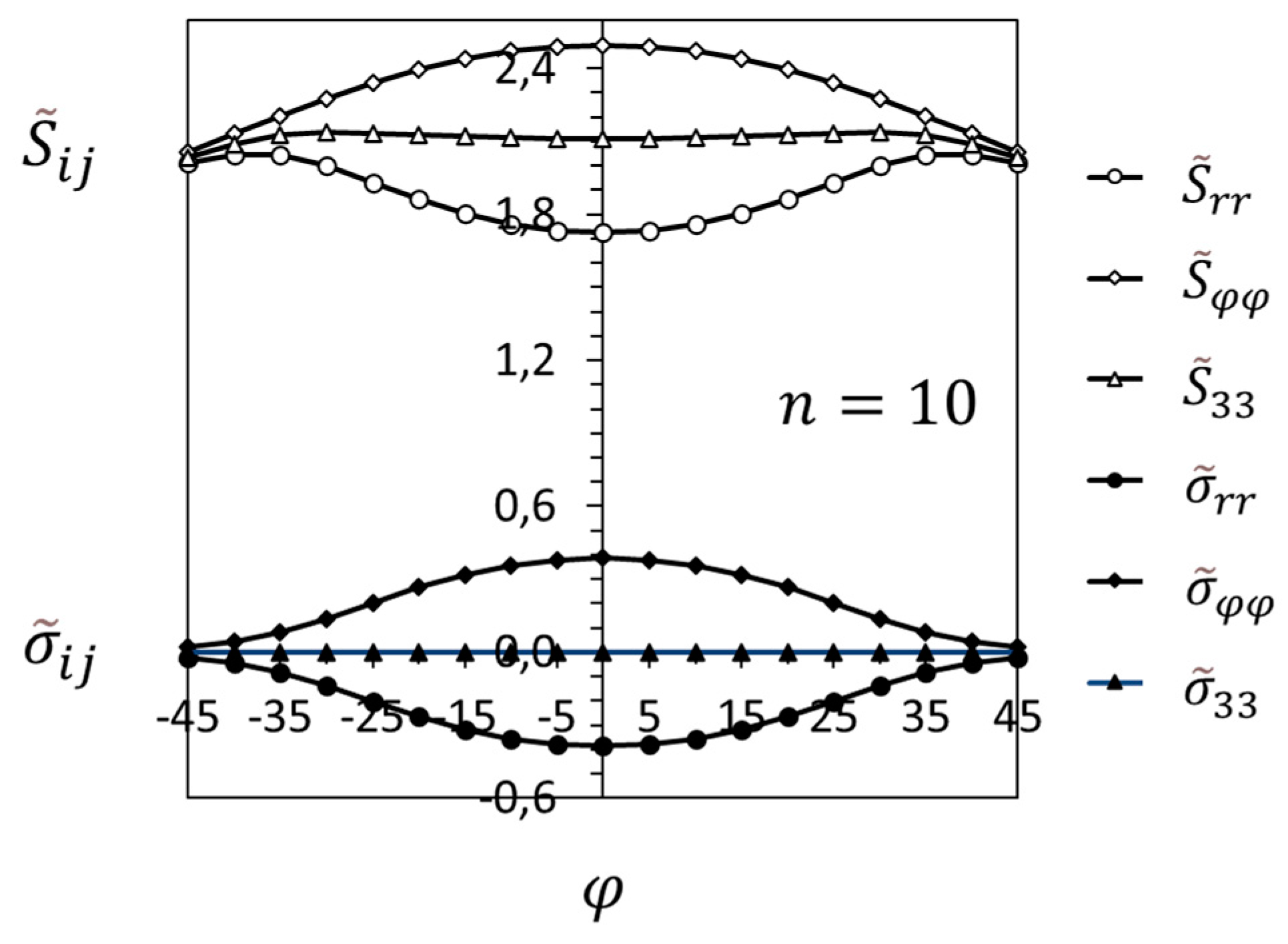
3.2. Crack-Tip Fields in the Hydride Precipitation Zone

Consider a crack in a hydride-forming alloy. According to the general analysis presented in [23], in the hydride precipitation zone ahead of the crack tip, the stress field is given by the following relations:
σ i j δ i j σ h z 3 = σ 0 J a σ 0 ε 0 I n r 1 n + 1 S ~ i j δ i j S ~ m m 3 = σ h z 1 a ε 0 I n r ~ 1 n + 1 S ~ i j δ i j S ~ m m 3 ,
σ 0 J a σ 0 ε 0 I n r 1 n + 1 = σ h z 1 a ε 0 I n r ~ 1 n + 1 ,
r ~ = r J σ h z σ 0 σ h z n   .
J is the J-integral [78]; I n is a dimensionless constant, which depends on the loading mode and hardening; and S ~ i j provides the angular variation in the stresses before hydride precipitation, i.e., of the HRR field [74,75]. The elaboration of relations (18)–(20) leads also to the following general relations:
σ i j σ h z δ i j 3 = 1 l 1 n + 1 F e p S ~ i j δ i j S ~ m m 3 = 1 l 1 n + 1 F e p σ ~ i j ,
F e p = 1 a ε 0 I n E / σ 0 n 1 n + 1 ,
l = r J σ h z E σ h z n   .
σ ~ i j provides the angular variation in the singular stress field in the hydride precipitation zone of the elastic–plastic material. According to (21), σ ~ m m = 0 . Therefore, although all stress components σ i j are singular, according to 1 l 1 n + 1 , the stress trace is constant and equal to σ h z . Also, based on the above relations and relation (14), the hydride volume fraction is determined as follows:
f E Z θ h r σ h z 1 2 ν = 1 l 1 n + 1 F e p S ~ m m 1 .
When the hydride volume fraction is set as equal to zero, the hydride precipitation zone boundary, l h z , is derived:
l h z φ ; n = F e p S ~ m m n + 1   .
The hydride precipitation zone boundary depends on the hardening exponent, n . According to relations (21)–(25), the non-dimensional crack-tip field in the hydride precipitation zone of an elastic–plastic material does not explicitly depend on the hydrogen concentration and mechanical loading. Any dependence on mechanical loading and hydrogen gas pressure and temperature is introduced via l , specified in (23), and σ h z , specified in (13). The effect of mechanical loading is introduced by J , while the effect of the average hydrogen content (thus, of the hydrogen gas pressure and temperature, based on Sievert’s law) is introduced by σ h z .
In the case of elastic material deformation, presented in [22], which is approached when n 1 , the stresses in the hydride precipitation zone satisfy the following relations, which are derived from relation (15), when   S i j is given by the K field (e.g., [61,79]):
σ i j σ h z δ i j 3 = 1 l 1 2 F e l S ~ i j e l δ i j S ~ m m e l 3 = 1 l 1 2 F e l σ ~ i j e l ,
F e l = 1 2 π 1 ν 2 1 2 ,
l = r G σ h z   ·   E σ h z ,
S ~ 11 e l = c o s φ 2 1 s i n φ 2 s i n 3 φ 2 ,
S ~ 22 e l = c o s φ 2 1 + s i n φ 2 s i n 3 φ 2 ,
S ~ 33 e l = 2 v   c o s φ 2 .
G is the energy release rate, which is equal to the J-integral. σ ~ i j e l provides the angular variation in the singular stress field in the hydride precipitation zone of the elastic material. As in the case of elastic–plastic deformation, according to (26), σ ~ m m e l = 0 . Then, in this case too, although all stress components σ i j are singular, according to l , the stress trace is constant and equal to σ h z . In addition, the hydride volume fraction and hydride precipitation zone boundary are given by the following relations:
f E Z θ h r σ h z 1 2 ν = 1 l 1 2 F e l S ~ m m e l 1 ,
l h z φ = F e l S ~ m m e l 2 .
Similarly to the case of an elastic–plastic material, according to relations (26)–(33), the non-dimensional crack-tip field in the hydride precipitation zone of an elastic material does not explicitly depend on the hydrogen concentration and mechanical loading; any such dependence is introduced via l and σ h z . The effect of mechanical loading is introduced by the energy-release rate, G , while the effect of the average hydrogen content is introduced by σ h z .
In the case of perfect plastic material deformation, presented in [24], which is approached when n , the stresses in the hydride precipitation zone sector, [−π/4, +π/4], satisfy the following relations, which are derived from relation (15), when   S i j is given by the Prandtl field [78,80]:
σ i j σ h z δ i j 3 = F p p S ~ i j p p δ i j S ~ m m p p 3   ,
F p p = σ 0 σ h z ,
S ~ 11 p p = π 3 ,
S ~ 22 p p = 2 + π 3 ,
S ~ 33 p p = 1 + π 3 .
As expected also from relation (21) when n , there is no spatial variation in stresses. Furthermore, based on the above relations (34)–(38), relation (15), and relation (14), the hydride volume fraction is derived as a constant value:
f E Z θ h r σ h z 1 2 ν = F p p S ~ m m p p 1 .
The hydride precipitation zone, as already mentioned, covers the sector π / 4 ,   π / 4   and, thus, l h z is infinite, based on asymptotic analysis; note that F p p S ~ m m p p n + 1 n .   It is useful to comment that the hydride precipitation zone is actually bounded by the surrounding remote stress field, within which hydrogen is in a solid solution and which depends on the structure. According to relations (34)–(39), the crack-tip field in the hydride precipitation zone of a non-hardening material depends on the average hydrogen content through the value of the hydride precipitation zone stress trace, σ h z .
Figure 6 presents the boundary of the hydride precipitation zone for α-Ti with the properties given in Table 3. In order to understand the effect of material deformation on the shape of the zone, the boundary is presented for three cases, namely, elastic deformation, elastic–plastic deformation with the hardening exponent, n , equal to 10, and perfectly plastic deformation; the boundaries have been derived based on relations (25) and (33). The lengths are normalized with the extent of the hydride precipitation zone on the crack plane ahead of the tip. Thus, Figure 6 does not indicate the actual size of the hydride precipitation zone; according to a previous analysis [23], the actual size, for the same mechanical loading and hydrogen content, increases significantly with the increase of n , i.e., as the deformation changes from elastic to elastic–plastic with decreasing hardening (which corresponds to increasing n ). It is emphasized that, in all cases, the π / 4 ,   π / 4 sector near the crack tip is a part of the hydride precipitation zone. Indeed, as it is known from the crack-tip fields before the precipitation of the hydrides (K field, HRR field, and Prandtl field), this is the sector of maximum hydrostatic stress, where hydrogen is attracted and hydride precipitation initiates. The hydride volume fraction within the hydride preciptation zone is calculated based on relations (32), (24), and (39), for elastic and elastic–plastic power-law hardening and perfectly plastic deformation, respectively. According to (24) and (32), the hydride volume fraction, f , increases sharply as the tip is approached, up to 1, which corresponds to the local volume completely occupied by hydride.
In the following figures, the stress distributions in the hydride precipitation zone are presented and compared with the field before hydride precipitation; the comparison is made ahead of the crack tip in the sector [−45°, 45°], which is a part of the hydride precipitation zone for all material behaviors, from elastic to elastic–plastic and perfectly plastic. In the cases of linear elastic and elastic–plastic with power-law hardening deformation, the stress distributions are singular, according to relations (26)–(31) and (21)–(23), respectively. In these cases, the angular distributions are given in Figure 7 and Figure 8, which show the significant deviations from the K field and HRR field in the hydride precipitation zone.
Figure 9 presents the significant deviation from the Prandtl field in the hydride precipitation zone ahead of the crack tip in a perfectly plastic material; the distributions correspond to the case of the hydride precipitation zone stress trace, σ h z , equal to 2 σ 0 . The stress distributions depend on the average hydrogen content, through the value of σ h z , according to relation (13); the larger the content of hydrogen, the smaller the value of the hydride precipitation zone stress trace. According to Figure 10 and relations (34)–(38), the deviation from the Prandtl field increases with the decrease in σ h z , which corresponds to an increase in the average hydrogen content.
The above analysis and results for hydride-forming alloys are directly applicable to single-phase alloys, such as α-Ti. The presence of phases of significantly different hydrogen solubilities, as in α-β Ti alloys, is currently under investigation. The deviations from the well-known K, HRR, and Prandtl fields are also expected. The outcome of the current research in progress will be presented in future publications.

4. Conclusions

Chemical Equilibrium Fracture Mechanics (CEFM) is a multidisciplinary approach for structural integrity assessments, based on the assumption of material deterioration under chemical equilibrium.
CEFM is applied to hydrogen embrittlement and the asymptotic stress and hydrogen concentration distributions are examined, ahead of a mode I plane strain crack, under constant temperature.
When hydrogen is in a solid solution, the HRR crack tip field in an elastic–plastic material, such as steel and Ni-based alloys, remains valid. The hydrogen concentration in the interstitial and trap sites is derived analytically; the traps are reversible either due to dislocations or precipitate/matrix interfaces. The hydrogen concentration in the interstitial sites near the crack tip is a function of the HRR field stress trace and average hydrogen content in the structure. The hydrogen concentration in the trap sites is directly calculated, based on the equilibrium of hydrogen in the trap and interstitial sites. It is shown that, in the cases of dislocation trap density, which is saturated with plastic deformation, as in steel, and a constant precipitate/matrix interface trap density, as in Ni-based X-750, the hydrogen concentrations in interstitial and trap sites at room temperature tend to become of equal importance when the average hydrogen content in the structure increases.
When hydride precipitation occurs, e.g., in Ti and Zr α-phase alloys, the crack-tip field in the hydride precipitation zone deviates significantly from the well-known K, HRR, and Prandtl fields, which are widely used in Linear Elastic Fracture Mechanics (LEFM) and Elastic–Plastic Fracture Mechanics (EPFM). The near-tip stress and hydride volume fraction distributions in the hydride precipitation zone are derived analytically for linear elastic, elastic–plastic with power-law hardening, and perfectly plastic material behavior.
The new analytical fields of the stress, hydrogen concentration, and hydride volume fraction near a crack tip are expected to facilitate the modification of structural integrity assessments, i.e., by extending LEFM and EPFM to CEFM. Along this direction, the critical stress intensity or J-integral values need to be derived for alloys of interest through combined fracture experiments of standard specimens in a hydrogen atmosphere and an analysis based on CEFM crack-tip fields.

Funding

This research received no external funding.

Data Availability Statement

No new data were created or analyzed in this study. Data sharing is not applicable to this article.

Acknowledgments

This study was performed within Euro-Harmonization and Engineering, an activity for the understanding of mechanics, related to present and future industrial needs.

Conflicts of Interest

The author declares no conflicts of interest.

References

  1. Brewer, T. Climate Change: An Interdisciplinary Introduction; Springer Nature: Cham, Switzerland, 2023. [Google Scholar]
  2. Nuttal, W.J.; Powel, J.B.; Anaya-Stucchi, K.L.; Bakenne, A.T.; Wilson, A. Insights into the New Hydrogen Economy; Springer Nature: Cham, Switzerland, 2025. [Google Scholar]
  3. Barrera, O.; Bombac, D.; Chen, Y.; Daff, T.D.; Galindo-Nava, E.; Gong, P.; Haley, D.; Horton, R.; Katzarov, I.; Kermode, J.R.; et al. Understanding and mitigating hydrogen embrittlement of steels: A review of experimental, modelling and design progress from atomistic to continuum. J. Mater. Sci. 2018, 53, 6251–6290. [Google Scholar] [CrossRef] [PubMed]
  4. Coleman, C.E. Cracking of hydride-forming metals and alloys. Compr. Struct. Integr. 2003, 6, 103–161. [Google Scholar]
  5. Takano, S.; Suzuki, T. An electron-optical study of β-hydride and hydrogen embrittlement of vanadium. Acta Metall. 1974, 22, 265–274. [Google Scholar] [CrossRef]
  6. Birnbaum, H.K.; Grossbeck, M.L.; Amano, M. Hydride precipitation in Nb and some properties of NbH. J. Less-Common Met. 1976, 49, 357–370. [Google Scholar] [CrossRef]
  7. Northwood, D.O.; Kosasih, U. Hydrides and delayed hydrogen cracking in zirconium and its alloys. Int. Met. Rev. 1983, 28, 92–121. [Google Scholar] [CrossRef]
  8. Shih, D.S.; Robertson, I.M.; Birnbaum, H.K. Hydrogen embrittlement of α titanium: In situ TEM studies. Acta Metall. 1988, 36, 111–124. [Google Scholar] [CrossRef]
  9. Lufrano, J.; Sofronis, P.; Birnbaum, H.K. Modeling of hydrogen transport and elastically accommodated hydride formation near a crack tip. J. Mech. Phys. Solids 1996, 44, 179–205. [Google Scholar] [CrossRef]
  10. Lufrano, J.; Sofronis, P.; Birnbaum, H.K. Elastoplastically accommodated hydride formation and embrittlement. J. Mech. Phys. Solids 1998, 46, 1497–1520. [Google Scholar] [CrossRef]
  11. Varias, A.G.; Massih, A.R. Simulation of hydrogen embrittlement in zirconium alloys under stress and temperature gradients. J. Nucl. Mater. 2000, 279, 273–285. [Google Scholar] [CrossRef]
  12. Varias, A.G.; Massih, A.R. Hydride-induced embrittlement and fracture in metals—Effect of stress and temperature distribution. J. Mech. Phys. Solids 2002, 50, 1469–1510. [Google Scholar] [CrossRef]
  13. Varias, A.G.; Feng, J.L. Simulation of hydride-induced steady-state crack growth in metals—Part I: Growth near hydrogen chemical equilibrium. Comput. Mech. 2004, 34, 339–356. [Google Scholar] [CrossRef]
  14. Varias, A.G.; Feng, J.L. Simulation of hydride-induced steady-state crack growth in metals—Part II: General near-tip field. Comput. Mech. 2004, 34, 357–376. [Google Scholar] [CrossRef]
  15. Winzer, N.; Atrens, A.; Dietzel, W.; Song, G.; Kainer, K.U. Evaluation of the delayed hydride cracking mechanism for transgranular stress corrosion cracking of magnesium alloys. Mater. Sci. Eng. A 2007, 466, 18–31. [Google Scholar] [CrossRef]
  16. Courty, O.; Motta, A.T.; Hales, J.D. Modeling and simulation of hydrogen behavior in Zircaloy-4 fuel cladding. J. Nucl. Mater. 2014, 452, 311–320. [Google Scholar] [CrossRef]
  17. Jernkvist, L.O.; Massih, A.R. Multi-field modelling of hydride forming metals Part I: Model formulation and validation. Comput. Mater. Sci. 2014, 85, 363–382. [Google Scholar] [CrossRef]
  18. Jernkvist, L.O. Multi-field modelling of hydride forming metals Part II: Application to fracture. Comput. Mater. Sci. 2014, 85, 383–401. [Google Scholar] [CrossRef]
  19. Abdolvand, H. Progressive modelling and experimentation of hydrogen diffusion and precipitation in anisotropic polycrystals. Int. J. Plast. 2019, 116, 39–61. [Google Scholar] [CrossRef]
  20. Xia, Z.; Zang, J.; Tong, Q.; Ding, S. Multi-physics modeling of delayed hydride cracking in zirconium alloys. J. Mech. Phys. Solids 2019, 132, 103677. [Google Scholar] [CrossRef]
  21. Ding, G.; Xia, Z.; Zhang, J.; Ding, S.; Pang, H.; Song, X.; Chen, L. Effects of irradiation on the multi-field coupling delayed hydride cracking behavior of zirconium alloys. J. Nucl. Mater. 2022, 563, 153605. [Google Scholar] [CrossRef]
  22. Varias, A.G. Elastic crack-tip field in hydride forming metals under hydrogen chemical equilibrium. Int. J. Fract. 2024, 245, 183–194. [Google Scholar] [CrossRef]
  23. Varias, A.G. Elastic-plastic crack-tip field in hydride forming metals under hydrogen chemical equilibrium. Int. J. Fract. 2024, 246, 47–57. [Google Scholar] [CrossRef]
  24. Varias, A.G. Hydride induced embrittlement and fracture of non-hardening metals under hydrogen chemical equilibrium. Int. J. Solids Struct. 2024, 305, 113073. [Google Scholar] [CrossRef]
  25. Voisey, K.T. The Engineer’s Guide to Materials. An Applications-Focused Introduction to Materials Science; Springer Nature: Cham, Switzerland, 2024. [Google Scholar]
  26. Joshi, S.; Martukanitz, R.P.; Nassar, A.R.; Michaleris, P. Additive manufacturing with Metals. Design, Processes, Materials, Quality Assurance, and Applications; Springer Nature: Cham, Switzerland, 2023. [Google Scholar]
  27. Coleman, C.E. The Metallurgy of Zirconium; International Atomic Energy Agency: Vienna, Austria, 2022; Volume 3. [Google Scholar]
  28. Teter, D.F.; Robertson, I.M.; Birnbaum, H.K. The effect of hydrogen on the deformation and fracture of β-Titanium. Acta Mater. 2001, 49, 4313–4323. [Google Scholar] [CrossRef]
  29. Li, X.; Zhang, J.; Fu, Q.; Akiyama, E.; Song, X.; Wang, Y.; Li, Q.; Zou, N. Tensile mechanical properties and fracture behaviors of nickel-based superalloy 718 in the presence of hydrogen. Int. J. Hydrog. Energy 2018, 43, 20118–20132. [Google Scholar] [CrossRef]
  30. Martin, M.L.; Dadfarnia, M.; Nagao, A.; Wang, S.; Sofronis, P. Enumeration of the hydrogen-enhanced localized plasticity mechanism for hydrogen embrittlement in structural materials. Acta Mater. 2019, 165, 734–750. [Google Scholar] [CrossRef]
  31. Troiano, A.R. The role of hydrogen and other interstitials in the mechanical behavior of metals. Trans. ASM 1960, 52, 54–80. [Google Scholar] [CrossRef]
  32. Oriani, R.A.; Josephic, P.H. Equilibrium aspects of hydrogen-induced cracking of steels. Acta Metall. 1974, 22, 1065–1074. [Google Scholar] [CrossRef]
  33. Oriani, R.A.; Josephic, P.H. Equilibrium and kinetic studies of hydrogen assisted cracking of steel. Acta Metall. 1977, 25, 979–988. [Google Scholar] [CrossRef]
  34. Birenis, D.; Ogawa, Y.; Matsunaga, H.; Takakuwa, O.; Yamabe, J.; Prytz, Ø.; Thøgersen, A. Hydrogen-assisted crack propagation in α-iron during elasto-plastic fracture toughness tests. Mater. Sci. Eng. A 2019, 756, 396–404. [Google Scholar] [CrossRef]
  35. Symons, D.M.; Thompson, A.W. The effect of hydrogen on the fracture of alloy X-750. Metall. Mater. Trans. A 1996, 27A, 101–110. [Google Scholar] [CrossRef]
  36. Beachem, C.D. A new model for hydrogen assisted cracking (hydrogen embrittlement). Metall. Trans. 1972, 3, 437–451. [Google Scholar] [CrossRef]
  37. Birnbaum, H.K.; Sofronis, P. Hydrogen enhanced localized plasticity—A mechanism for hydrogen related fracture. Mater. Sci. Eng. 1994, A176, 191–202. [Google Scholar] [CrossRef]
  38. Zhang, Z.; Obasi, G.; Morana, R.; Preuss, M. In-situ observation of hydrogen induced crack initiation in a nickel-based superalloy. Scr. Mater. 2017, 140, 40–44. [Google Scholar] [CrossRef]
  39. Robertson, I.M.; Birnbaum, H.K. An HVEM study of hydrogen effects on the deformation and fracture of nickel. Acta Metall. 1986, 34, 353–366. [Google Scholar] [CrossRef]
  40. Lynch, S.P. Environmentally assisted cracking: Overview of evidence for an adsorption-induced localized-slip process. Acta Metall. 1988, 36, 2639–2661. [Google Scholar] [CrossRef]
  41. Sofronis, P.; McMeeking, R.M. Numerical analysis of hydrogen transport near a blunting crack tip. J. Mech. Phys. Solids 1989, 37, 317–350. [Google Scholar] [CrossRef]
  42. Lufrano, J.; Sofronis, P.; Symons, D. Hydrogen transport and large strain elastoplasticity near a notch in alloy X-750. Eng. Fract. Mech. 1998, 59, 827–845. [Google Scholar] [CrossRef]
  43. Krom, A.H.M.; Koers, R.W.J.; Bakker, A. Hydrogen transport near a blunting crack tip. J. Mech. Phys. Solids 1999, 47, 971–992. [Google Scholar] [CrossRef]
  44. Varias, A.G.; Warren, R. Distribution of Hydrogen in Interstitial Lattice Sites and Saturable Traps, Ahead of a Steadily Growing Crack—Mathematical Model and Numerical Algorithm; Malmö University: Malmö, Sweden, 2001; PA-06-12-01. [Google Scholar] [CrossRef]
  45. Kanayama, H.; Ndong-Mefane, S.; Ogino, M.; Miresmaeili, R. Reconsideration of the Hydrogen Diffusion Model Using the McNabb-Foster Formulation; Memoirs of the Faculty of Engineering, Kyushu University: Fukuoka, Japan, 2009; Volume 69, pp. 149–161. [Google Scholar]
  46. Di Leo, C.V.; Anand, L. Hydrogen in metals: A coupled theory for species diffusion and large elastic–plastic deformations. Int. J. Plast. 2013, 43, 42–69. [Google Scholar] [CrossRef]
  47. Dadfarnia, M.; Martin, M.L.; Nagao, A.; Sofronis, P.; Robertson, I.M. Modeling hydrogen transport by dislocations. J. Mech. Phys. Solids 2015, 78, 511–525. [Google Scholar] [CrossRef]
  48. Zhang, Z.; Peeters, J.; Popovich, V.; Ayas, C. Combined effects of stress and temperature on hydrogen diffusion in non-hydride forming alloys applied in gas turbines. Int. J. Hydrog. Energy 2022, 47, 30687–30706. [Google Scholar] [CrossRef]
  49. Varias, A.G. Hydrogen Distribution in Metals Under Chemical Equilibrium and Steady-State Heat Conduction; EH-29122022; Euro Harmonization and Engineering: N. Iraklio, Greece, 2022. [Google Scholar] [CrossRef]
  50. Denbigh, K.G. The Thermodynamics of the Steady State; Methuen & CO.: London, UK, 1951. [Google Scholar]
  51. Shewmon, P. Diffusion in Solids; The Minerals, Metals & Materials Society: Warrendale, PA, USA, 1989. [Google Scholar]
  52. Nagumo, M. Fundamentals of Hydrogen Embrittlement; Springer Nature: Singapore, 2023. [Google Scholar]
  53. Johnson, H.H.; Quick, N.; Kumnick, A.J. Hydrogen trapping mechanisms by permeation techniques. Scr. Metall. 1979, 13, 67–72. [Google Scholar] [CrossRef]
  54. Oriani, R.A. The diffusion and trapping of hydrogen in steel. Acta Metall. 1970, 18, 147–157. [Google Scholar] [CrossRef]
  55. Krom, A.H.M.; Bakker, A.D. Hydrogen trapping models in steel. Metall. Mater. Trans. B 2000, 31B, 1475–1482. [Google Scholar] [CrossRef]
  56. Shi, R.; Nie, Z.; Fan, Q.; Wang, F.; Zhou, Y.; Liu, X. Correlation between dislocation-density-based strain hardening and microstructural evolution in dual phase TC6 titanium alloy. Mater. Sci. Eng. A 2018, 715, 101–107. [Google Scholar] [CrossRef]
  57. Nabarro, F.R.N. The strains produced by precipitation in alloys. Proc. R. Soc. 1940, A175, 519–538. [Google Scholar]
  58. Eshelby, J.D. The determination of the elastic field of an ellipsoidal inclusion, and related problems. Proc. R. Soc. 1957, A241, 376–396. [Google Scholar]
  59. Lee, J.K.; Earmee, Y.Y.; Aaronson, H.I.; Russell, K.C. Plastic relaxation of the transformation strain energy of a misfitting spherical precipitate: Ideal plastic behavior. Metall. Trans. A 1980, 11A, 1837–1847. [Google Scholar] [CrossRef]
  60. Earmee, Y.Y.; Johnson, W.C.; Lee, J.K. Plastic relaxation of the transformation strain energy of a misfitting spherical precipitate: Linear and power-law strain hardening. Metall. Trans. A 1981, 12A, 1521–1530. [Google Scholar]
  61. Broberg, K.B. Cracks and Fracture; Academic Press: London, UK, 1999. [Google Scholar]
  62. Ashby, M.F.; Jones, D.R.H. Engineering Materials 2: An Introduction to Microstructures, Processing and Design; Pergamon: Oxford, UK, 1986. [Google Scholar]
  63. Hertzberg, R.W. Deformation and Fracture Mechanics of Engineering Materials; John Wiley & Sons: New York, NY, USA, 1983. [Google Scholar]
  64. Hirth, J.P. Effects of hydrogen on the properties of iron and steel. Metall. Trans. A 1980, 11A, 861–890. [Google Scholar] [CrossRef]
  65. Kumnick, A.J.; Johnson, H.H. Deep trapping states for hydrogen in deformed iron. Acta Metall. 1980, 28, 33–39. [Google Scholar] [CrossRef]
  66. Special Metals Alloy Technical Bulletins. Available online: https://www.specialmetals.com/documents/technical-bulletins/inconel/inconel-alloy-x-750.pdf (accessed on 31 October 2024).
  67. Baranowski, B.; Majchrzak, S.; Flanagan, T.B. The volume increase of fcc metals and alloys due to interstitial hydrogen over a wide range of hydrogen contents. J. Phys. F Met. Phys. 1971, 1, 258–261. [Google Scholar] [CrossRef]
  68. Senkov, O.N.; Dubois, M.; Jonas, J.J. Elastic moduli of titanium-hydrogen alloys in the temperature range 20 °C to 1100 °C. Metall. Mater. Trans. A 1996, 27A, 3963–3970. [Google Scholar] [CrossRef]
  69. Alvarez, A.M.; Robertson, I.M.; Birnbaum, H.K. Hydrogen embrittlement of a metastable β-titanium alloy. Acta Mater. 2004, 52, 4161–4175. [Google Scholar] [CrossRef]
  70. Waisman, J.L.; Sines, G.; Robinson, L.B. Diffusion of hydrogen in titanium alloys due to composition, temperature, and stress gradients. Metall. Trans. 1973, 4, 291–302. [Google Scholar] [CrossRef]
  71. Vitt, R.S.; Ono, K. Hydrogen solubility in alpha titanium. Metall. Trans. 1971, 2, 608–609. [Google Scholar] [CrossRef]
  72. Pardee, W.J.; Paton, N.E. Model of sustained load cracking by hydride growth in Ti alloys. Metall. Trans. A 1980, 11A, 1391–1400. [Google Scholar] [CrossRef]
  73. Chen, C.Q.; Li, S.X.; Zheng, H.; Wang, L.B.; Lu, K. An investigation on structure, deformation and fracture of hydrides in titanium with a large range of hydrogen contents. Acta Mater. 2004, 52, 3697–3706. [Google Scholar] [CrossRef]
  74. Hutchinson, J.W. Singular behaviour at the end of a tensile crack in a hardening material. J. Mech. Phys. Solids 1968, 16, 13–31. [Google Scholar] [CrossRef]
  75. Rice, J.R.; Rosengren, G.F. Plane strain deformation near a crack tip in a power-law hardening material. J. Mech. Phys. Solids 1968, 16, 1–12. [Google Scholar] [CrossRef]
  76. San Marchi, C.; Somerday, B.P.; Robinson, S.L. Permeability, solubility and diffusivity of hydrogen isotopes in stainless steels at high gas pressures. Int. J. Hydrog. Energy 2007, 32, 100–116. [Google Scholar] [CrossRef]
  77. Symington, M.; Shih, C.F.; Ortiz, M. Tables of Plane Strain Mixed-Mode Plastic Crack Tip Fields; Brown University: Providence, RI, USA, 1988; MRG/DMR-8714665/1. [Google Scholar]
  78. Rice, J.R. A path independent integral and the approximate analysis of strain concentration by notches and cracks. J. Appl. Mech. 1968, 35, 379–387. [Google Scholar] [CrossRef]
  79. Williams, M.L. On the stress distribution at the base of a stationary crack. J. Appl. Mech. 1957, 24, 109–114. [Google Scholar] [CrossRef]
  80. Hutchinson, J.W. Plastic stress and strain fields at a crack tip. J. Mech. Phys. Solids 1968, 16, 337–347. [Google Scholar] [CrossRef]
Figure 1. Chemical Equilibrium Fracture Mechanics is a multidisciplinary approach for the evaluation of structural integrity under chemical equilibrium and steady-state energy transfer.
Cmd 06 00005 g001
Figure 2. Hydrogen concentration in interstitial lattice sites ahead of a crack tip on the crack plane of ASTM A 106 Grade B steel at 20 °C, normalized by remote hydrogen concentration in interstitial lattice sites. Distances have been normalized by J-integral [78] over yield stress.
Cmd 06 00005 g002
Figure 3. Hydrogen concentration in interstitial lattice sites on the plane of deformation, normal to the crack edge, for an ASTM A 106 Grade B steel at 20 °C. Hydrogen concentration has been normalized by remote hydrogen concentration in interstitial lattice sites. Distances have been normalized by J-integral [78] over yield stress.
Cmd 06 00005 g003
Figure 4. Variation in the ratio of hydrogen concentration in trap sites over hydrogen concentration in interstitial lattice sites with the remote hydrogen concentration in interstitial lattice sites, for different stress trace levels, expected ahead of a crack tip; ASTM A 106 Grade B steel at 20 °C.
Cmd 06 00005 g004
Figure 5. Variation in the ratio of hydrogen concentration in trap sites over hydrogen concentration in interstitial lattice sites with the remote hydrogen concentration in interstitial lattice sites, for different stress trace levels, expected ahead of a crack tip; X-750 Ni-Cr-Fe alloy at (a) 25 °C and (b) 285 °C.
Cmd 06 00005 g005
Figure 6. Change in hydride precipitation zone shape as the deformation behavior of the metal changes from linear elastic to elastic–plastic with power-law hardening and perfectly plastic deformation. With the exception of the hardening exponent, the properties of the material correspond to α-Ti, given in Table 3.
Cmd 06 00005 g006
Figure 7. Angular variation in the singular stress field before, S ~ i j e l , and after hydride precipitation, σ ~ i j e l , ahead of the crack tip in the sector [−45°, 45°] when material deformation is described by linear elasticity. The properties of the material correspond to α-Ti, given in Table 3.
Cmd 06 00005 g007
Figure 8. Angular variation in the singular stress field before, S ~ i j , and after hydride precipitation, σ ~ i j , ahead of the crack tip in the sector [−45°, 45°] under elastic–plastic power-law hardening behavior with n = 10 . The properties of the material correspond to α-Ti, given in Table 3.
Cmd 06 00005 g008
Figure 9. Angular variation in the stress field before, S i j , and after hydride precipitation, σ i j , ahead of the crack tip in the sector [−45°, 45°] under perfect plastic deformation; stresses are normalized by yield stress. Remote hydrogen concentration corresponds to σ h z / σ 0 = 2 . The properties of the material correspond to α-Ti, given in Table 3.
Cmd 06 00005 g009
Figure 10. Angular variation in the stress field, σ i j , ahead of the crack tip in the hydride precipitation sector [−45°, 45°] under perfect plastic deformation for various levels of hydride precipitation zone stress trace, σ h z ; stresses are normalized by yield stress. The properties of the material correspond to α-Ti, given in Table 3.
Cmd 06 00005 g010
Table 1. Material properties of steel, used in the present analysis, with yield and ultimate tensile strength approaching those of ASTM A 106 Grade B at 20 °C.
Material Property (Units) Reference
E (GPa)210 [62]
ν0.3[63]
σ 0 (MPa)250
n 20calculation
V ¯ H (m3/mol)2 × 10−6[64]
V ¯ (m3/mol)7.1 × 10−6calculation
Δ E T (kJ/mol)59.9[65]
N T   for   ε ¯ p 1 (m−3 · mol−1) 10 23 / N A [65]
β6[55]
Table 2. Material properties of X-750 Ni-Cr-Fe alloy (UNS N07750, solution annealed and precipitation hardened, Type 3 according to ASTM B 637), used in the present analysis.
Material Property (Units) Reference
E (GPa)214 (at 25 °C)
196 (at 285 °C)
[66]
ν0.29[66]
σ 0 (MPa)810 (at 25 °C)
735 (at 285 °C)
[35]
n 15calculation
V ¯ H (m3/mol)1.72 × 10−6[35,42,67]
V ¯ (m3/mol)6.87 × 10−6[42]
Δ E T (kJ/mol)15.1[35,42]
N T (m−3 · mol−1) 6 × 10 26 / N A [42]
β1[42,55]
Table 3. Material properties of α-phase titanium used in the present analysis, with yield and ultimate tensile strength approaching those ASTM B 265 Grade 1 unalloyed titanium (UNS R50250).
Material Property (Units) Reference
E (GPa)110 [68]
ν0.34[68]
σ 0 (MPa)140 1
V ¯ H (m3/mol)1.7 × 10−6[69,70]
V ¯ (m3/mol)10.62 × 10−6calculation
C e T S (mol/m3)3.8478 × 105 exp(−20,951.28/RT)[71]
V ¯ h r (m3/mol)13.17 × 10−6calculation
θ h r 0.24[72]
x 1.5 2 e.g., [73]
1 Calculations have been performed for elastic deformation, perfectly plastic deformation, and elastic–plastic power-law hardening deformation with hardening exponent, n , equal to 10. 2 δ-hydride surrounded by α-Ti matrix.
Disclaimer/Publisher’s Note: The statements, opinions and data contained in all publications are solely those of the individual author(s) and contributor(s) and not of MDPI and/or the editor(s). MDPI and/or the editor(s) disclaim responsibility for any injury to people or property resulting from any ideas, methods, instructions or products referred to in the content.

