

Distinctive Oxide Films Develop on the Surface of FeCrAl as the Environment Changes for Nuclear Fuel Cladding


Abstract
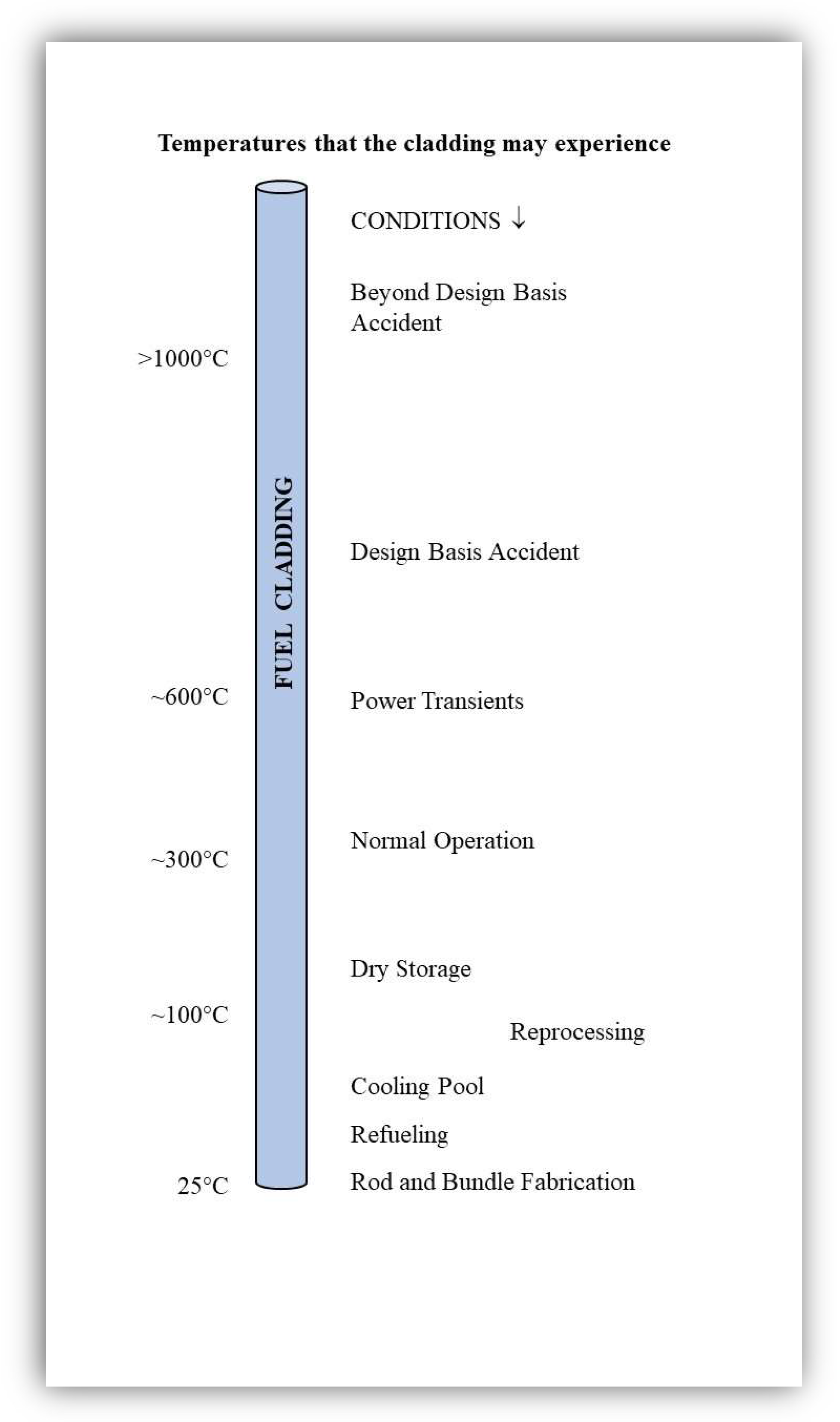
1. Introduction
2. Rod and Bundle Fabrication
3. Oxidation of FeCrAl Cladding under LWR Normal Operation Conditions
4. General Corrosion of FeCrAl Alloys in Out-of-Pile Autoclave Tests at ~300 °C
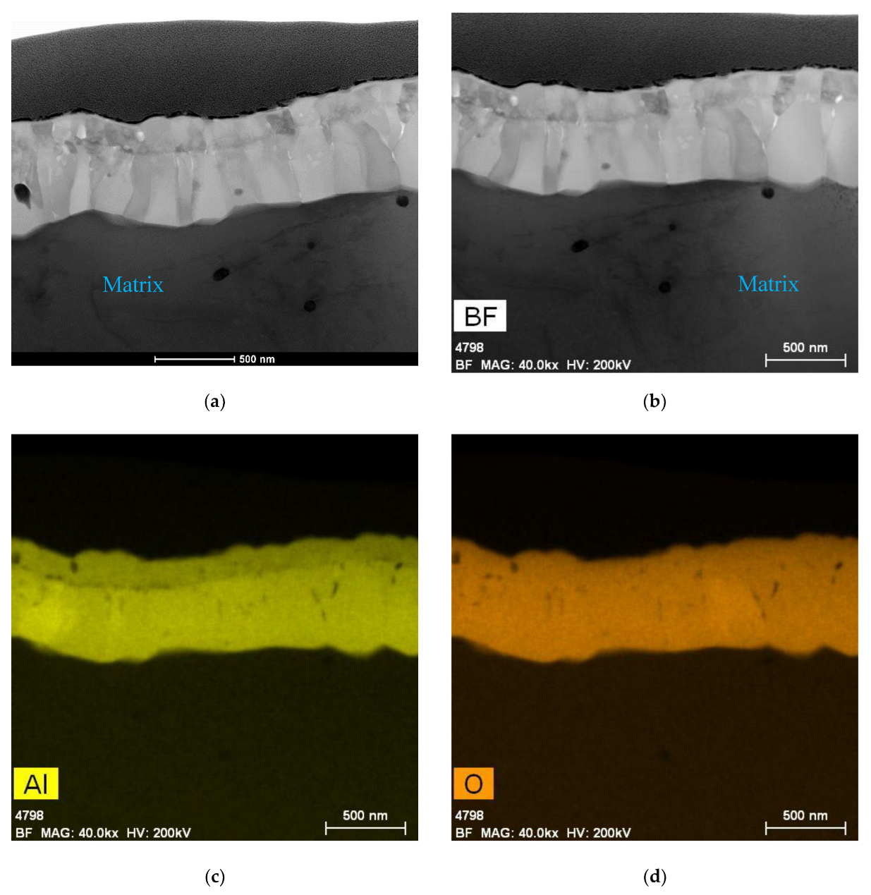
5. Composition of the Oxides Developed on FeCrAl in Out-of-Pile Autoclave Tests at ~300 °C
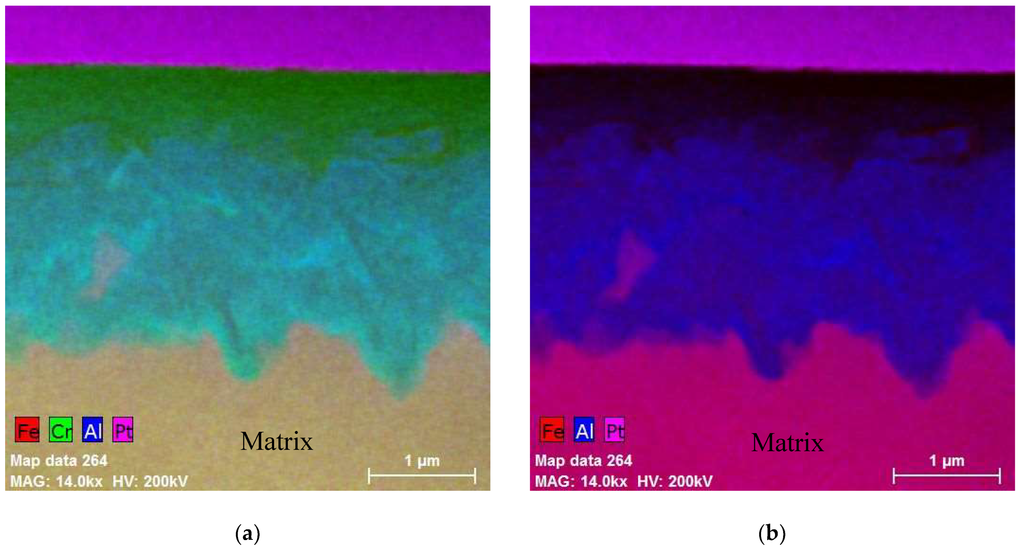
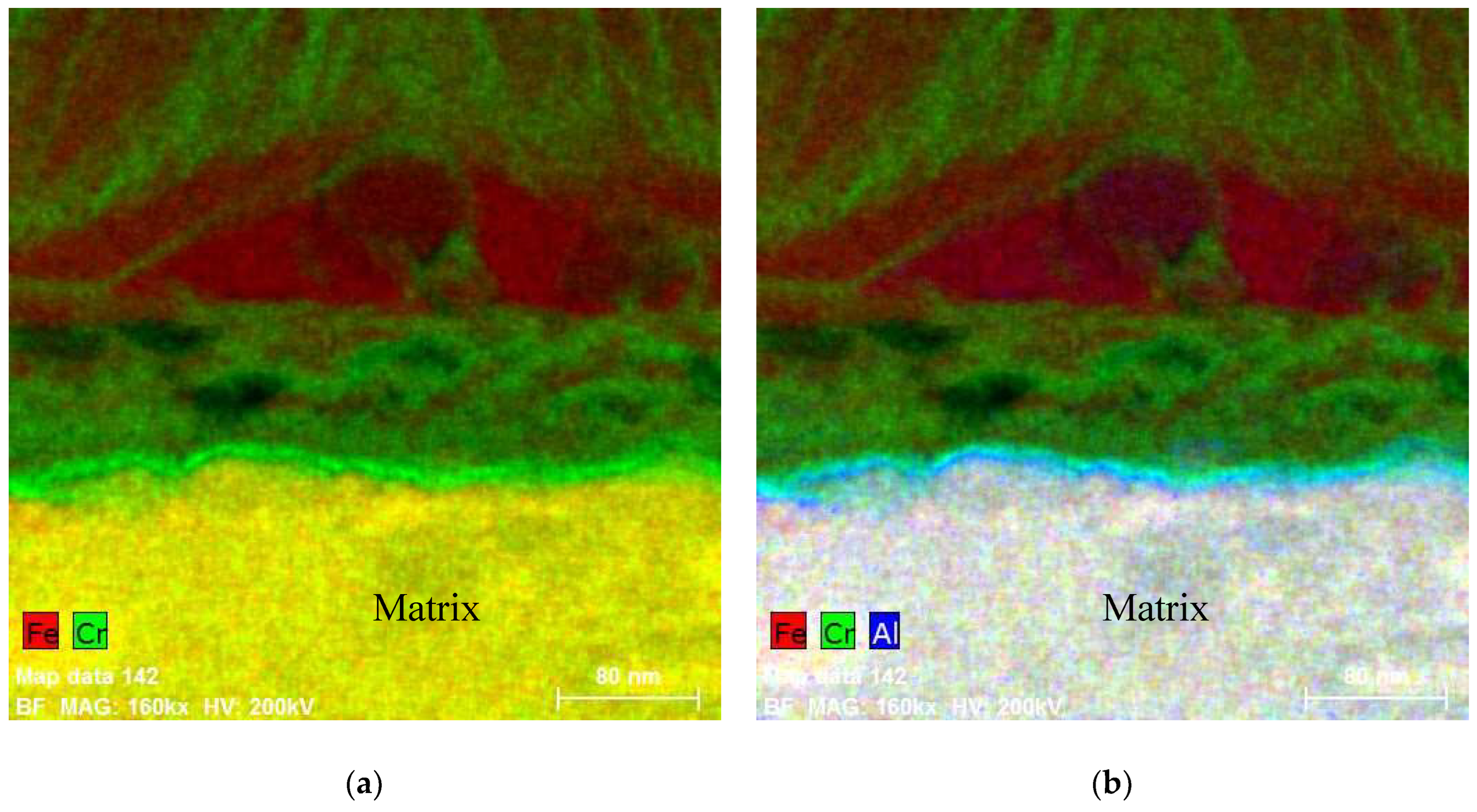
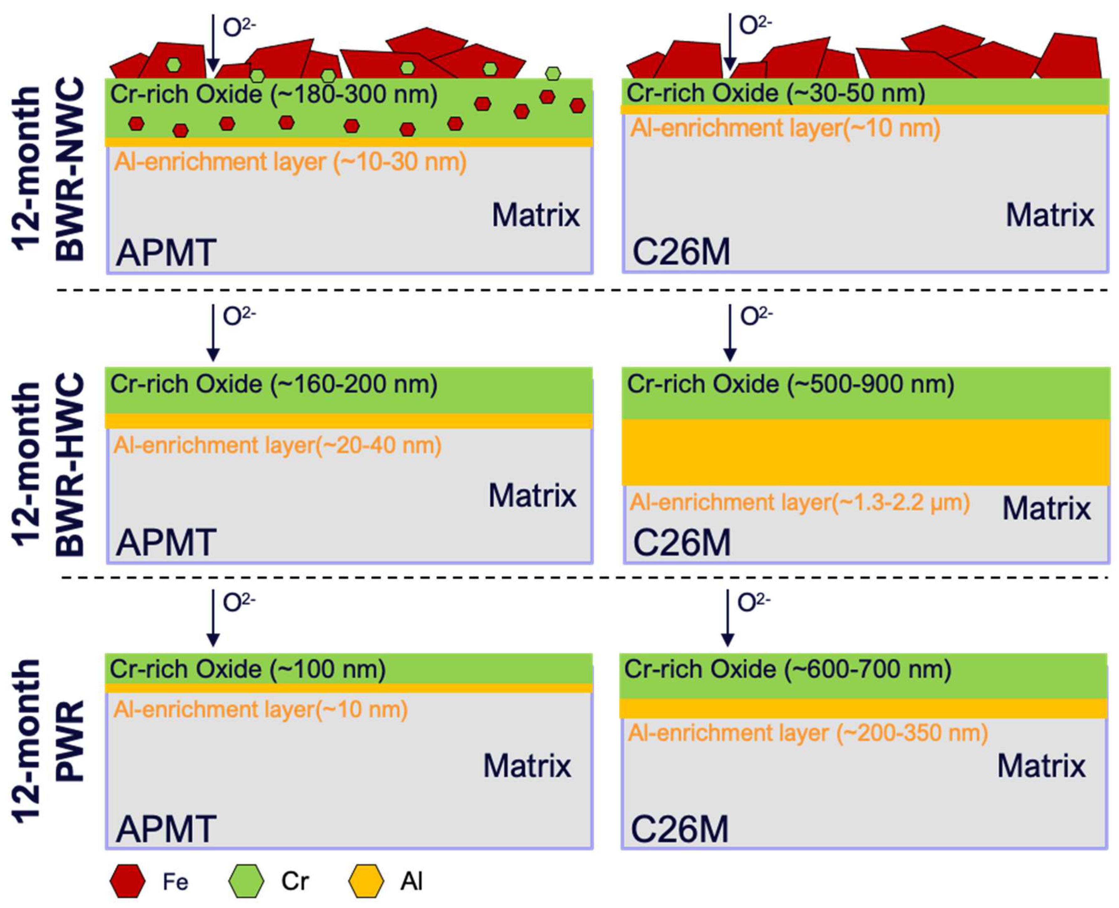
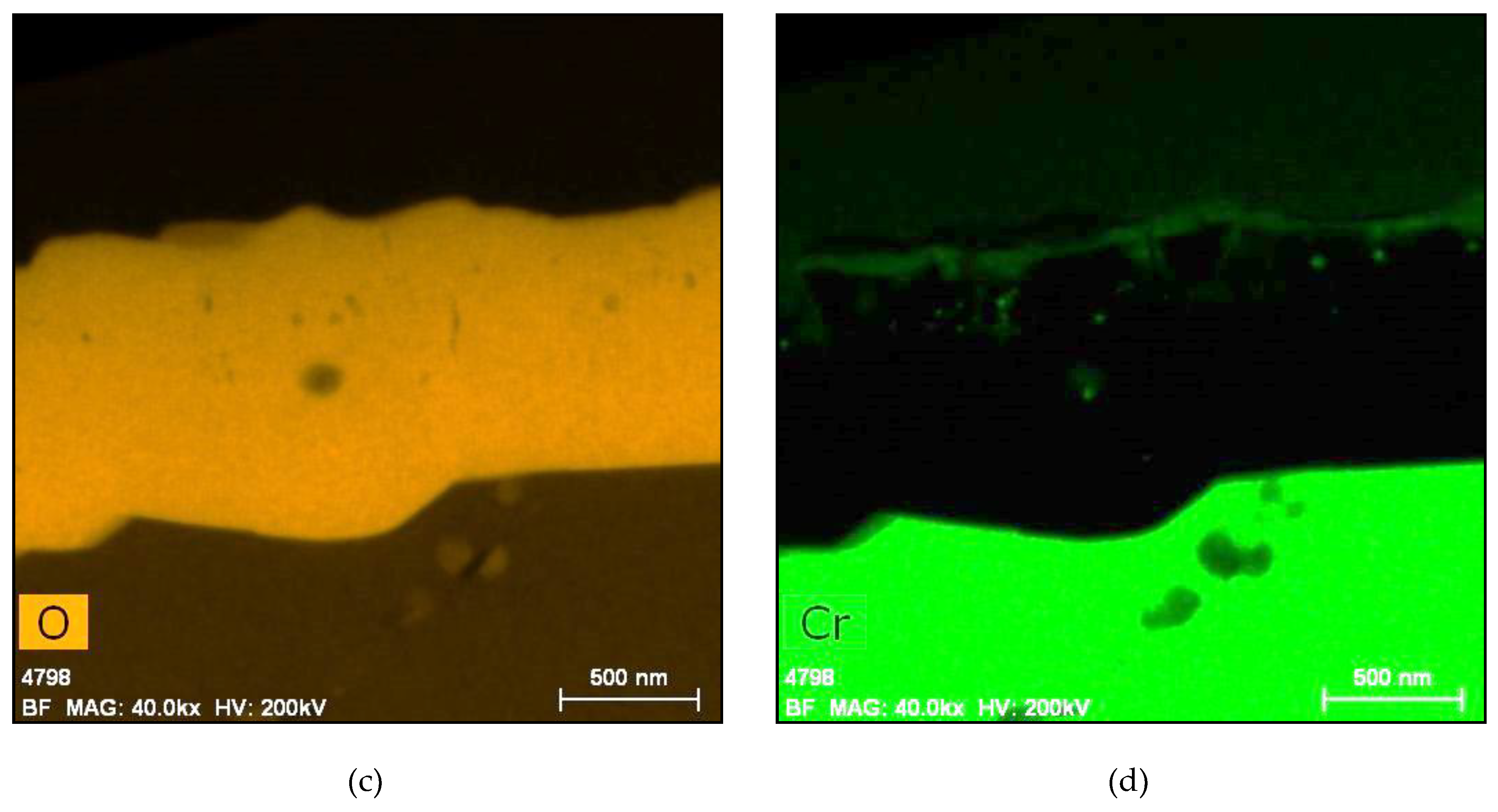
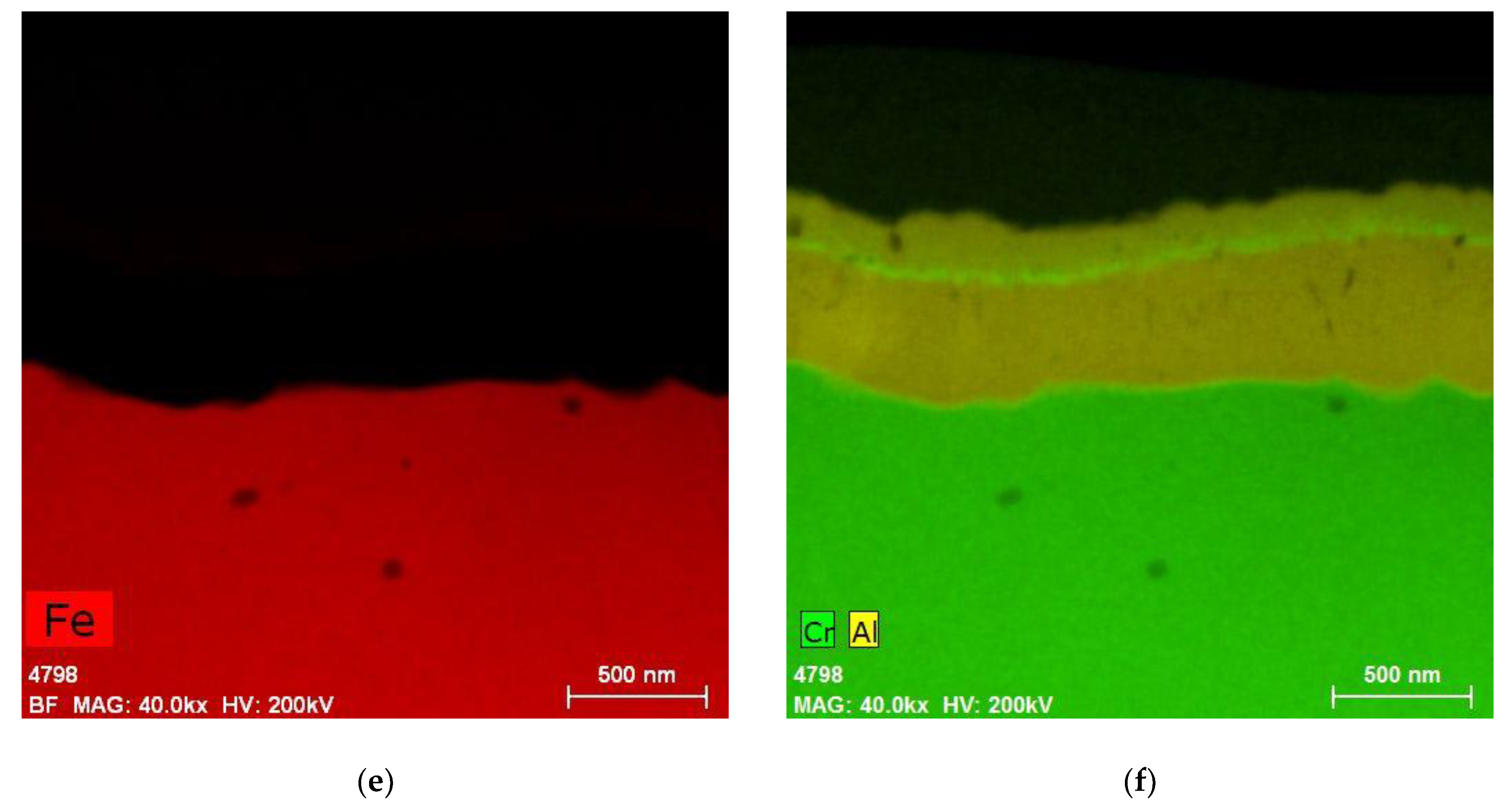
5.1. Oxides under Oxidizing Conditions (BWR NWC)
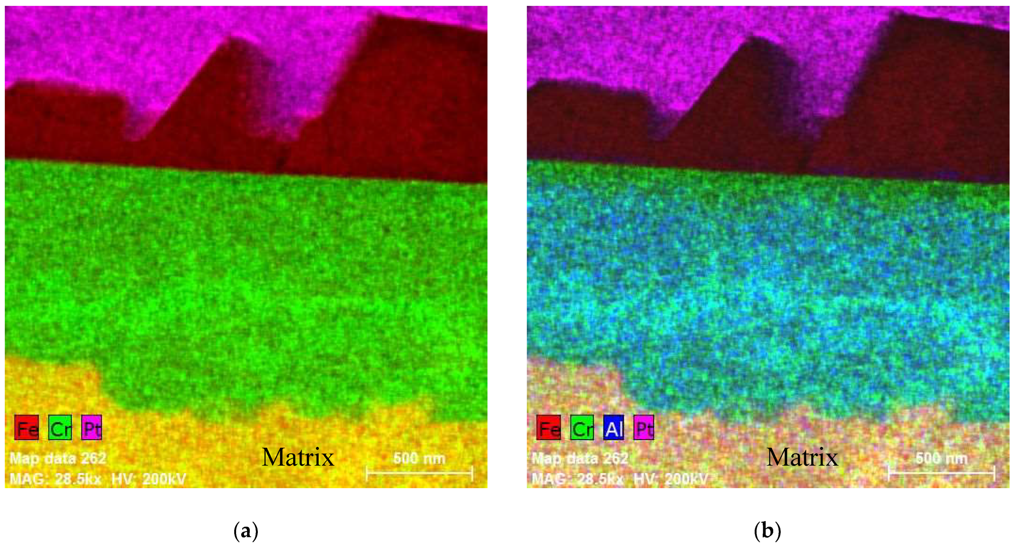
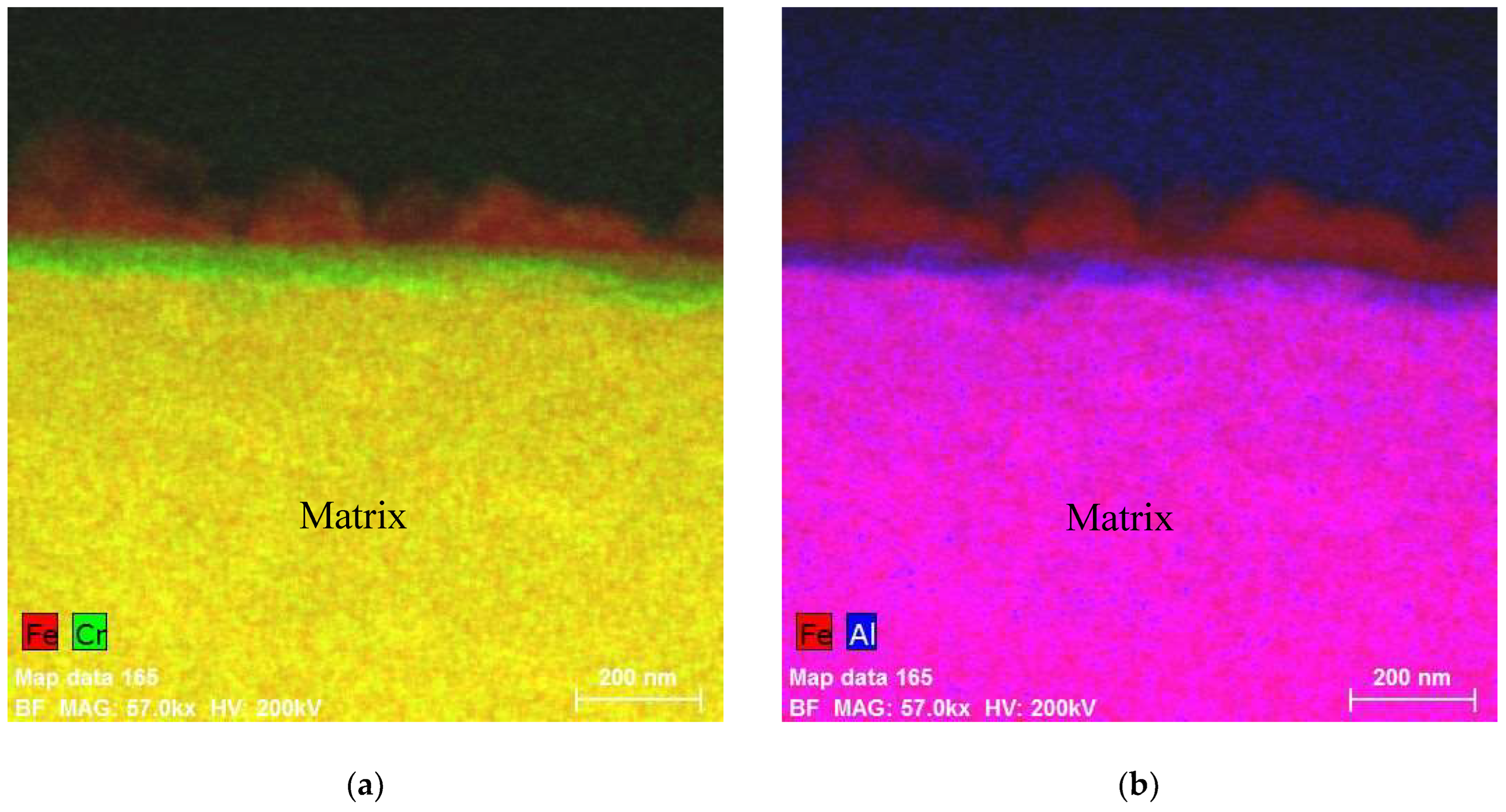
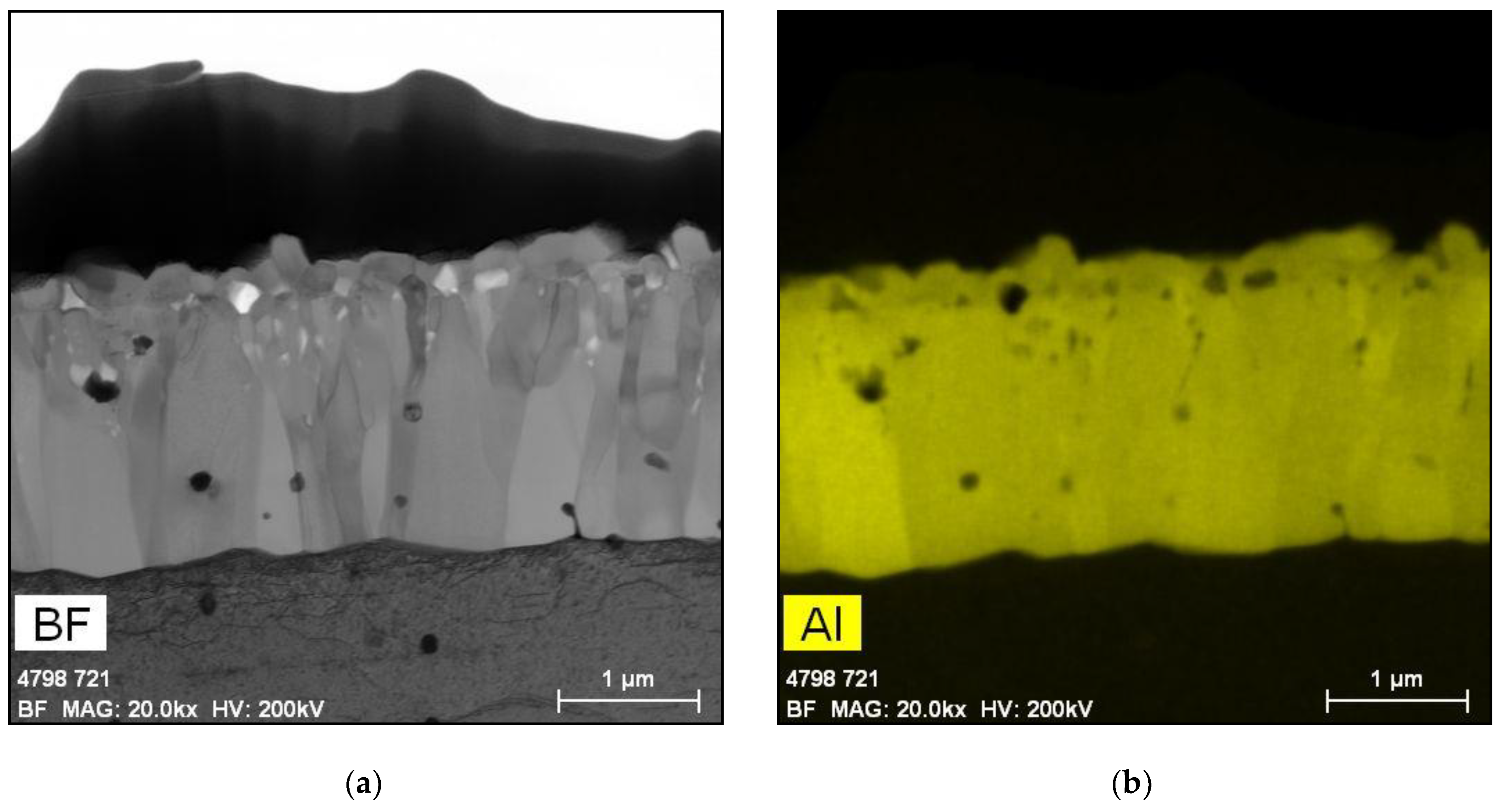
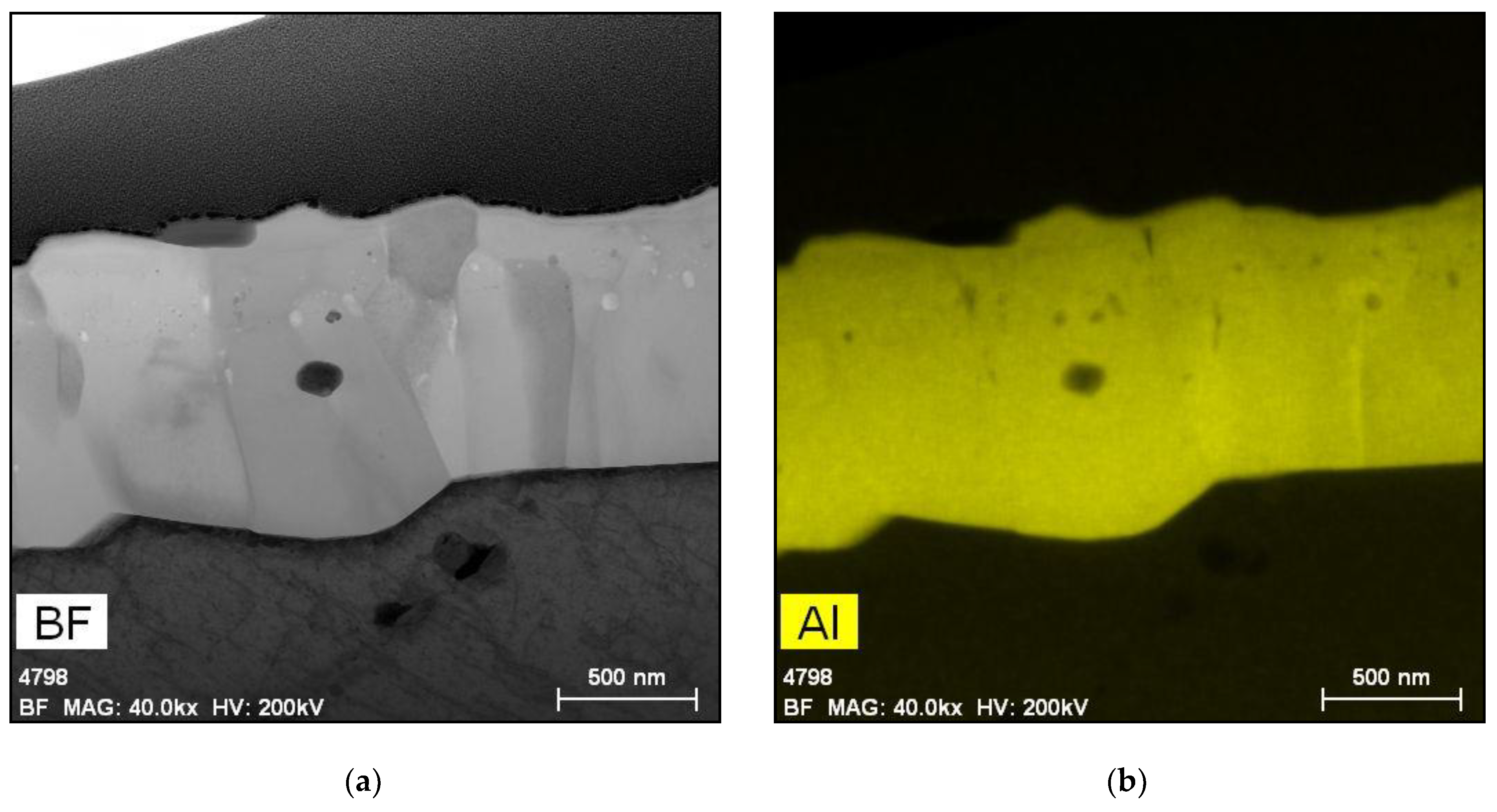
5.2. Oxides Developed under Reducing Conditions (BWR HWC and PWR)
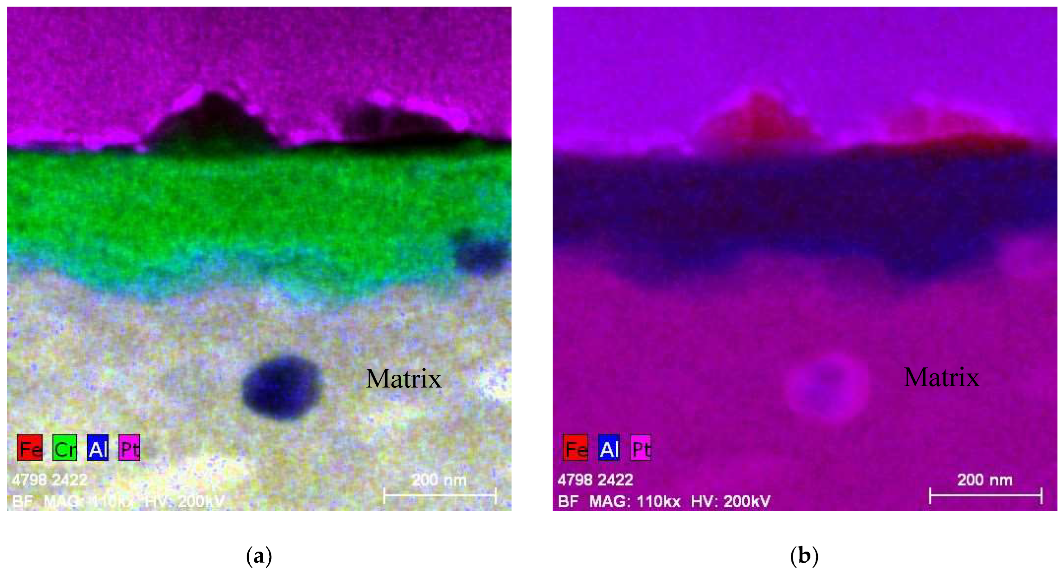
6. Oxide Film Development during Accident Conditions
6.1. Design-Basis Accident Conditions (DBA)
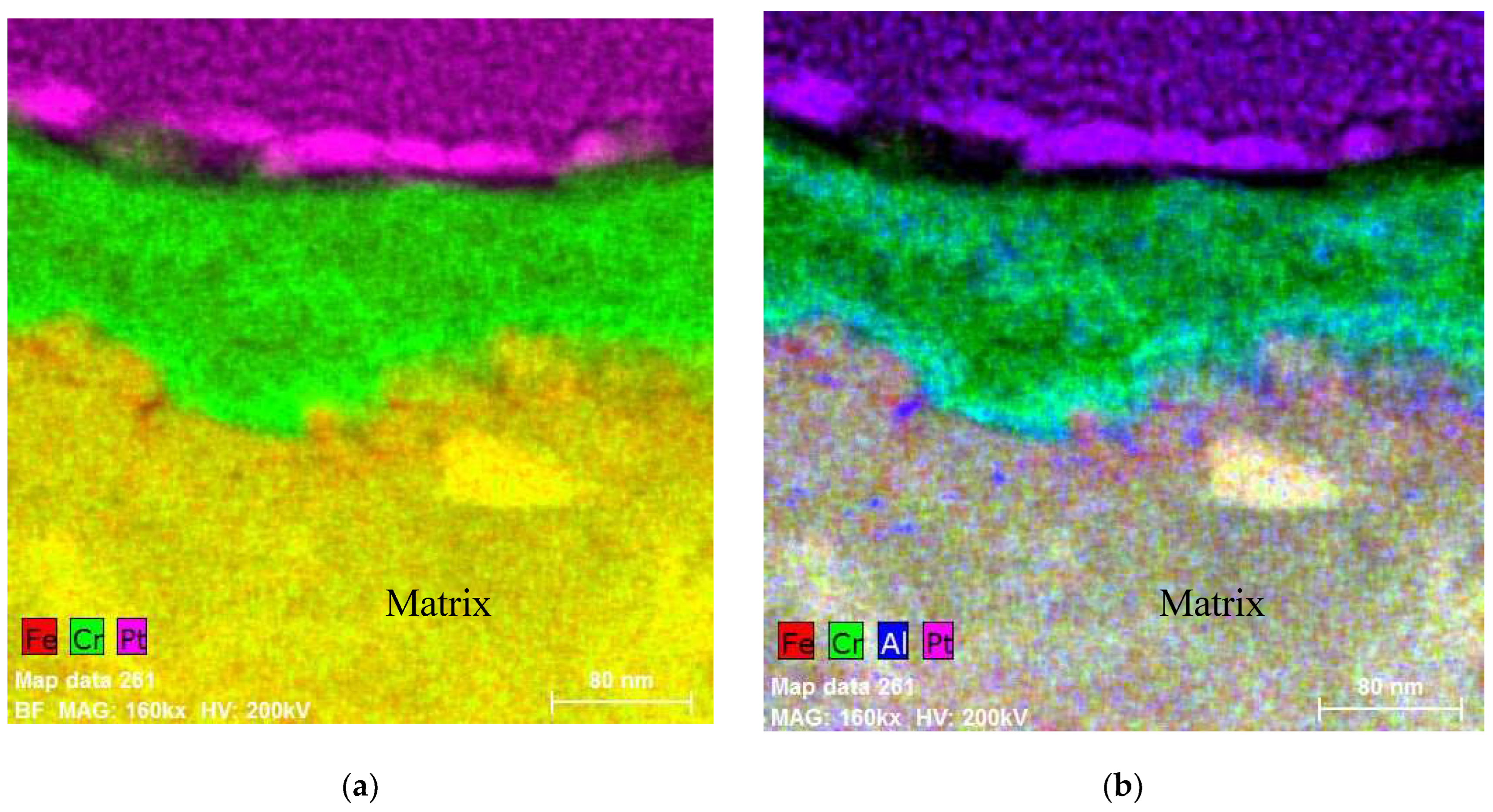
6.2. Beyond Design-Basis Accidents (BDBA)
7. FeCrAl Alloy Oxidation Behavior in Other Environments
7.1. Industrially Pre-Oxidized APMT in Air
7.2. Passive Behavior of FeCrAl in Cooling Pools
7.3. Passive Behavior in Air under Dry Cask Storage
7.4. Effect of FeCrAl Alloy Composition on Dissolution in Mineral Acids
8. Conclusions
Author Contributions
Funding
Data Availability Statement
Conflicts of Interest
References
- Huang, S.; Dolley, E.; An, K.; Yu, D.; Crawford, C.; Othon, M.A.; Spinelli, I.; Knussman, M.P.; Rebak, R.B. Microstructure and Tensile Behavior of Powder Metallurgy FeCrAl Accident Tolerant Fuel Cladding. J. Nucl. Mater. 2022, 560, 153524. [Google Scholar] [CrossRef]
- Yin, L.; Jurewicz, T.B.; Larsen, M.; Drobnjak, M.; Graff, C.C.; Lutz, D.R.; Rebak, R.B. Uniform Corrosion of FeCrAl Cladding Tubing for Accident Tolerant Fuels in Light Water Reactors. J. Nucl. Mater. 2021, 554, 153090. [Google Scholar] [CrossRef]
- Qu, H.J.; Abouelella, H.; Chikhalikar, A.S.; Rajendran, R.; Roy, I.; Priedeman, J.; Umretiya, R.; Hoffman, A.; Wharry, J.P.; Rebak, R. Effect of Nickel on the Oxidation Behavior of FeCrAl Alloy in Simulated PWR and BWR Conditions. Corros. Sci. 2023, 216, 111093. [Google Scholar] [CrossRef]
- Chikhalikar, A.; Roy, I.; Abouelella, H.; Umretiya, R.; Hoffman, A.; Larsen, M.; Rebak, R.B. Effect of Aluminum on the FeCr(Al) Alloy Oxidation Resistance in Steam Environment at Low Temperature (400 °C) and High Temperature (1200 °C). Corros. Sci. 2022, 209, 110765. [Google Scholar] [CrossRef]
- Rajendran, R.; Chikhalikar, A.S.; Roy, I.; Abouelella, H.; Qu, H.J.; Umretiya, R.V.; Hoffman, A.K.; Rebak, R.B. Effect of Aging and α’ Segregation on Oxidation and Electrochemical Behavior of FeCrAl Alloys. J. Nucl. Mater. 2024, 588, 154751. [Google Scholar] [CrossRef]
- Roy, I.; Abouelella, H.; Rajendran, R.; Chikhalikar, A.S.; Larsen, M.; Umretiya, R.; Hoffman, A.; Rebak, R. Effect of Al Concentration on Fe-17Cr Alloy during Steam Oxidation at 400 °C. Corros. Sci. 2023, 217, 111135. [Google Scholar] [CrossRef]
- Rebak, R.B.; Yin, L.; Zhang, W.; Umretiya, R.V. Effect of the Redox Potential on the General Corrosion Behavior of Industrial Nuclear Alloys. J. Nucl. Mater. 2023, 576, 154257. [Google Scholar] [CrossRef]
- Jurewicz, T.; Rebak, R. Electrochemistry of FeCrAl Fuel Cladding in High Temperature Water. Trans. Am. Nucl. Soc. 2018, 118, 17–21. [Google Scholar]
- Terrani, K.A. Accident Tolerant Fuel Cladding Development: Promise, Status, and Challenges. J. Nucl. Mater. 2018, 501, 13–30. [Google Scholar] [CrossRef]
- Field, K.G.; Snead, M.A.; Yamamoto, Y.; Terrani, K.A. Handbook on the Material Properties of FeCrAl Alloys for Nuclear Power Production Applications (FY18 Version: Revision 1); Oak Ridge National Lab. (ORNL): Oak Ridge, TN, USA, 2018.
- Sakamoto, K.; Miura, Y.; Ukai, S.; Oono, N.H.; Kimura, A.; Yamaji, A.; Kusagaya, K.; Takano, S.; Kondo, T.; Ikegawa, T.; et al. Development of Accident Tolerant FeCrAl-ODS Fuel Cladding for BWRs in Japan. J. Nucl. Mater. 2021, 557, 153276. [Google Scholar] [CrossRef]
- Qu, Z.; Meng, C.; Huang, J.; Mei, Y.; Zhang, Y.; Ma, J.; Liu, W.; Wang, H.; He, X. Mechanistic Study of Incipient Corrosion for Nuclear Grade Lean-Cr FeCrAl Alloys in a Simulated PWR Environment. Mater. Des. 2023, 230, 111948. [Google Scholar] [CrossRef]
- Terrani, K.A.; Pint, B.A.; Kim, Y.-J.; Unocic, K.A.; Yang, Y.; Silva, C.M.; Meyer, H.M.; Rebak, R.B. Uniform Corrosion of FeCrAl Alloys in LWR Coolant Environments. J. Nucl. Mater. 2016, 479, 36–47. [Google Scholar] [CrossRef]
- Raiman, S.S.; Field, K.G.; Rebak, R.B.; Yamamoto, Y.; Terrani, K.A. Hydrothermal Corrosion of 2nd Generation FeCrAl Alloys for Accident Tolerant Fuel Cladding. J. Nucl. Mater. 2020, 536, 152221. [Google Scholar] [CrossRef]
- Ning, F.; Wang, X.; Yang, Y.; Tan, J.; Zhang, Z.; Jia, D.; Wu, X.; Han, E.-H. Uniform Corrosion Behavior of FeCrAl Alloys in Borated and Lithiated High Temperature Water. J. Mater. Sci. Technol. 2021, 70, 136–144. [Google Scholar] [CrossRef]
- Yamashita, S.; Ioka, I.; Nemoto, Y.; Kawanishi, T.; Kurata, M.; Kaji, Y.; Fukahori, T.; Nozawa, T.; Sato, D.; Murakami, N.; et al. Overview of Accident-Tolerant Fuel R&D Program in Japan. In Proceedings of the 14th International Nuclear Fuel Cycle Conference, GLOBAL 2019 and Light Water Reactor Fuel Performance Conference, TOP FUEL 2019, Seattle, WA, USA, 22–27 September 2019. [Google Scholar]
- Rebak, R.; Jurewicz, T.; Larsen, M.; Sakamoto, K. Immersion Testing of FeCrAl Tubes under Simulated Light Water Nuclear Reactor Normal Operation Conditions. In Proceedings of the Top Fuel 2019 Conference, Seattle, WA, USA, 22–27 September 2019. [Google Scholar]
- Jiang, G.; Xu, D.; Feng, P.; Guo, S.; Yang, J.; Li, Y. Corrosion of FeCrAl Alloys Used as Fuel Cladding in Nuclear Reactors. J. Alloys Compd. 2021, 869, 159235. [Google Scholar] [CrossRef]
- Was, G.S.; Allen, T.R. Corrosion in Advanced Nuclear Reactors. Electrochem. Soc. Interface 2021, 30, 57. [Google Scholar] [CrossRef]
- Qu, H.J.; Chikhalikar, A.S.; Abouelella, H.; Roy, I.; Rajendran, R.; Nagothi, B.S.; Umretiya, R.; Hoffman, A.K.; Rebak, R.B. Effect of Molybdenum on the Oxidation Resistance of FeCrAl Alloy in Lower Temperature (400 °C) and Higher Temperature (1200 °C) Steam Environments. Corros. Sci. 2024, 229, 111870. [Google Scholar] [CrossRef]
- Pint, B.A. Performance of FeCrAl for Accident-Tolerant Fuel Cladding in High-Temperature Steam. Corros. Rev. 2017, 35, 167–175. [Google Scholar] [CrossRef]
- Qian, L.; Liu, Y.; Huang, T.; Chen, W.; Du, S.; Yin, C.; Xiong, Q. Research Progress in High-Temperature Thermo-Mechanical Behavior for Modelling FeCrAl Cladding under Loss-of-Coolant Accident Condition. Prog. Nucl. Energy 2023, 164, 104848. [Google Scholar] [CrossRef]
- Yan, Y.; Harp, J.; Coq, A.L.; Massey, C.; Linton, K. High-Temperature Steam Oxidation Study of Irradiated FeCrAl Defueled Specimens. J. Nucl. Mater. 2024, 590, 154868. [Google Scholar] [CrossRef]
- Rebak, R.B. Accident-Tolerant Materials for Light Water Reactor Fuels; Elsevier: Amsterdam, The Netherlands, 2020. [Google Scholar]
- Rebak, R.B.; Gupta, V.K.; Larsen, M. Oxidation Characteristics of Two FeCrAl Alloys in Air and Steam from 800 °C to 1300 °C. JOM 2018, 70, 1484–1492. [Google Scholar] [CrossRef]
- Lipkina, K.; Hallatt, D.; Geiger, E.; Fitzpatrick, B.W.N.; Sakamoto, K.; Shibata, H.; Piro, M.H.A. A Study of the Oxidation Behaviour of FeCrAl-ODS in Air and Steam Environments up to 1400 °C. J. Nucl. Mater. 2020, 541, 152305. [Google Scholar] [CrossRef]
- Rebak, R.B.; Yin, L.; Jurewicz, T.B.; Hoffman, A.K. Acid Dissolution Behavior of Ferritic FeCrAl Tubes Candidates for Nuclear Fuel Cladding. Corrosion 2021, 77, 1321–1331. [Google Scholar] [CrossRef]


| Alloy | Cr | Al | Others |
|---|---|---|---|
| C26M | 12 | 6 | 2Mo, 0.2Si, 0.03Y |
| APMT | 21 | 5 | 3Mo, 0.4Mn, 0.7Si |
| FeCrAl ODS | 12 | 6 | 0.5Ti, 0.4Zr, 0.5Y2O3 |
| APM | 21 | 5.8 | 0.7Si, 0.4Mn |
| Aluchrom Y Hf | 20 | 6 | 0.1Y, 0.1Hf, Si, Mn |
Disclaimer/Publisher’s Note: The statements, opinions and data contained in all publications are solely those of the individual author(s) and contributor(s) and not of MDPI and/or the editor(s). MDPI and/or the editor(s) disclaim responsibility for any injury to people or property resulting from any ideas, methods, instructions or products referred to in the content. |
© 2024 by the authors. Licensee MDPI, Basel, Switzerland. This article is an open access article distributed under the terms and conditions of the Creative Commons Attribution (CC BY) license (https://creativecommons.org/licenses/by/4.0/).
Share and Cite
Qu, H.; Yin, L.; Larsen, M.; Rebak, R.B. Distinctive Oxide Films Develop on the Surface of FeCrAl as the Environment Changes for Nuclear Fuel Cladding. Corros. Mater. Degrad. 2024, 5, 109-123. https://doi.org/10.3390/cmd5010006
Qu H, Yin L, Larsen M, Rebak RB. Distinctive Oxide Films Develop on the Surface of FeCrAl as the Environment Changes for Nuclear Fuel Cladding. Corrosion and Materials Degradation. 2024; 5(1):109-123. https://doi.org/10.3390/cmd5010006
Chicago/Turabian StyleQu, Haozheng, Liang Yin, Michael Larsen, and Raul B. Rebak. 2024. "Distinctive Oxide Films Develop on the Surface of FeCrAl as the Environment Changes for Nuclear Fuel Cladding" Corrosion and Materials Degradation 5, no. 1: 109-123. https://doi.org/10.3390/cmd5010006
APA StyleQu, H., Yin, L., Larsen, M., & Rebak, R. B. (2024). Distinctive Oxide Films Develop on the Surface of FeCrAl as the Environment Changes for Nuclear Fuel Cladding. Corrosion and Materials Degradation, 5(1), 109-123. https://doi.org/10.3390/cmd5010006