Review

Corrosion at the Steel–Medium Interface

by
Robert E. Melchers
Centre for Infrastructure Performance and Reliability, The University of Newcastle, Callaghan, NSW 2308, Australia
Corros. Mater. Degrad. 2024, 5(1), 52-72; https://doi.org/10.3390/cmd5010003
Submission received: 6 December 2023 / Revised: 31 December 2023 / Accepted: 23 January 2024 / Published: 29 January 2024

Abstract

:
Corrosion on the interface between a metal alloy, such as steel, and a wet, permeable non-metallic medium is of considerable practical interest. Examples include the interface between steel and water, the atmosphere or concrete, as for steel reinforcement bars; between metal and soil, as for buried cast iron or steel pipes; deposits of some type, as in under-deposit corrosion; and the interface with insulation, protective coatings, or macro- or micro-biological agents. In all cases, corrosion initiation depends on the characteristics of the interfacial zone, both of the metal and the medium, and the spatial variability. For (near-)homogeneous semi-infinite media with good interfacial contact, the pitting, crevices and general corrosion of the metal will be largely controlled by the metal (micro-)characteristics, including its inclusions, imperfections and surface roughness. In other cases, these may be overshadowed by the macro-characteristics of the medium and the degree of interfacial contact, possibly with severe resulting corrosion. Where the build-up of corrosion products can occur at the interface, they will dominate longer-term corrosion and govern the long-term corrosion rate. For media of finite thickness, diffusion issues and material deterioration may also be involved. The practical implications are outlined. It is argued that with the presence of a suitable medium, it is possible to achieve negligible long-term corrosion but only if certain practical actions are taken.

1. Introduction

Corrosion is usually considered a process that involves the properties and characteristics of the interface between, on the one side, a metal or alloy and, on the other side, some external environment, such as the atmosphere; water; other fluid; or some, perhaps permeable, solid material, either of finite thickness or approximated as semi-infinite. The latter may be collectively classed as examples of different ‘media’ in interfacial contact with a metal or alloy. For simplicity, the discussion herein is limited to steel and non-metallic media. The latter includes water, the atmosphere or concrete, as for steel reinforcement bars; soil, as for buried cast iron or steel pipes; deposits of some type, as in under-deposit corrosion; insulation, as in corrosion under insulation or protective coatings; or macro- or micro-biological agents in contact with the steel. Galvanic corrosion between the medium and the steel is not considered, nor is cathodic protection for which modern perspectives have become available [1,2]. In passing, some remarks are also made about alloys other than steel and metallic media.
As might be expected, the interface between the steel and the medium plays a critical role in the initiation and subsequent development of corrosion. That role changes somewhat with the development of corrosion products on the interface and the change from oxygen reduction to hydrogen evolution as the main cathodic reaction. It will become evident that there is a degree of duality in the roles played by the steel and the medium for corrosion at the interface. Noting that the common forms of corrosion, such as ‘uniform, general, pitting, crevice and under-deposit’, ultimately all have the same underlying mechanism—a difference in potential—it is shown that the differences between the steel and the medium, at least for shorter-term corrosion, are the result of local circumstances and scale. These may drive the total amount of corrosion in the early stages, with carry-over effects to later times, but as the corrosion progresses, these earlier influences become less important, and the longer-term rates of corrosion are barely affected by them. Improved understanding of these relationships exposes a degree of unity and will contribute to improving the modelling of the development of the longer-term corrosion behaviour relevant to many infrastructure applications. It also should shed new light on the mechanisms involved in specific industry-related corrosion problems, such as corrosion in soils, under protective coatings and under insulation.
The next section provides a rather high-level review of the initiation and very early development of corrosion for irons and steels exposed to a homogeneous isotropic medium, such as water or a wet atmosphere. It then reverts to the conventional scenario in which the physical, chemical and metallurgical properties of the steel, and specifically those at the interface, are the prime drivers of the corrosion process. This is classical material. This section also provides a step-by-step picture of what happens at the corrosion interface soon after the first exposure, depending on the conditions of, and on, the steel surface. The following section considers scenarios in which the properties of the medium are the drivers of corrosion initiation and early corrosion development, specifically the influence of a permeable, not necessarily homogeneous and isotropic, semi-infinite medium on corrosion initiation is considered, working from recent observations for the corrosion of ferrous metals in soils and steel in concretes. This is then extended to other media of finite thickness, such as protective coatings and insulation materials for which diffusion issues and material deterioration also may be involved, although the latter are not considered in detail herein. The effect of longer exposure periods and further corrosion on the interface between the metal and the medium is then considered, specifically the role of the development of corrosion products in the interfacial region and the effect this has on longer-term corrosion rates, including for pitting and average corrosion loss. Some observations are then made about practical implications and applicability to alloys other than steels.

2. Classical Models for Corrosion Initiation and Early Development

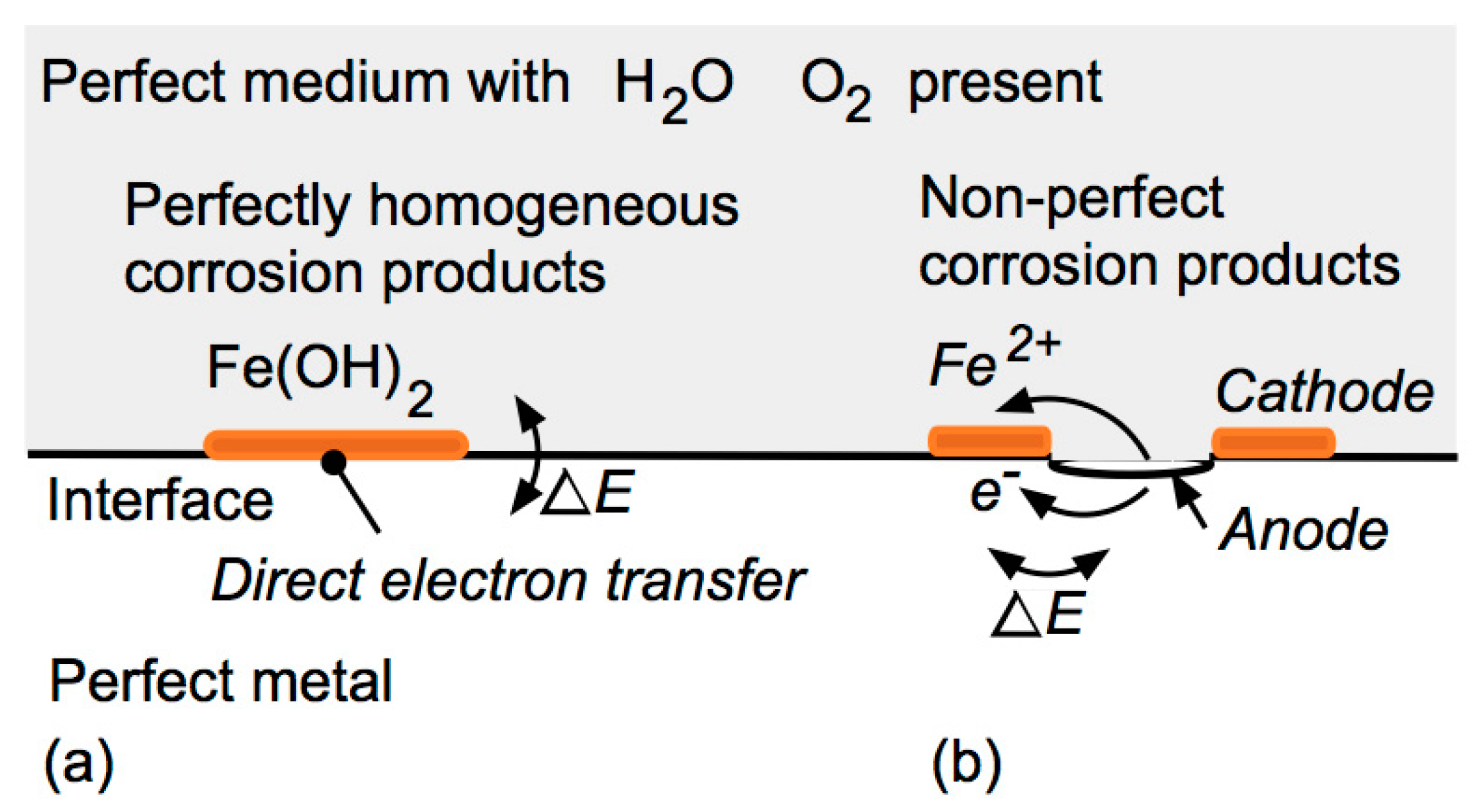
2.1. ‘Pure’ Metal in Contact with a Wet Homogeneous (Pure) Medium

For a pure metal in pure water, the possibility of whether corrosion of a metal will occur depends, in the terminology of physical chemistry, on the net (Gibbs) free energy (ΔG) of the reactants potentially involved—in other words, there must be a release of energy for the reaction to proceed. Conventionally, this is denoted by ΔG < 0, indicating the reaction, as written and for which ΔG was derived, is thermodynamically feasible. This condition on equilibrium thermodynamics provides no information about what happens immediately after the reaction commences or the speed of the reaction. It also provides no information about the destination or fate of the reaction products. As will be seen, the latter is probably the most important aspect of practical infrastructure-related corrosion problems.
For ferrous corrosion, the reaction of interest is that for (pure) iron in (pure oxygenated) water at neutral pH:
2Fe + O2 + 2H2O → 2Fe(OH)
As it stands, this is simply a chemical reaction. There can be a transfer of electrons from iron as the electron donor (Fe → Fe2+ + 2e) to oxygen as the electron acceptor (O2 + 2e → O2−). This takes place across the interface, with the electrons being transferred from one substance to the other without a specific electron flow, that is, without a corrosion current. It is facilitated by the intimate contact between the components in (1). Further, for ideal materials, implying a perfect interface, there should be no preferential location for Reaction (1)—thus the reaction should, in theory, occur all over the metal surface exposed everywhere to water and oxygen. Thus, the possibility of localized effects is excluded.
As soon as Reaction (1) proceeds, however, the situation changes since the corrosion products are likely to form a barrier at the interface, reducing the access of O2 and H2O to the metal surface. For the reaction to continue, it is necessary for these to diffuse through the corrosion products while electron transfer continues by direct contact at the (slowly changing) interface. Except in an ideal situation, it is likely that the corrosion products that form will not do so in an ideal manner but instead form a spatially imperfect, non-uniform and inhomogeneous layer. In an advanced form, this can be seen, for example, in atmospheric rusts [3] (p. 408). It follows that it is likely that the diffusion processes required for the continuation of Reaction (1) will also be non-uniform across the surface. While in the early stages, concentration polarization (or control) is the likely rate-controlling step [3] (p. 84) rather than diffusion, it does mean that the necessary conditions for corrosion as conventionally understood arise very quickly, even before attention is turned to the non-homogeneities of the materials.
Before proceeding, it is useful to note that the estimation of ΔG for a particular reaction requires the form of that reaction to be known and to be stoichiometrically correct. In general, the estimation of ΔG requires knowledge of the entropy and the enthalpy (of formation) of each of the potential components in the reaction, as well as the temperature T at which the reaction is expected to operate. For a wide variety of substances (solids, liquids, gases, solutions, elements, compounds), the values for entropy, enthalpy and free energy are available [4]. These values are based on experimental observations for what are assumed to be pure substances, i.e., they contain no alloying elements or inclusions or defects, such as cracks.
For corrosion work, it is more conventional to work with electrochemical potential E. These have also been tabulated [3]. Theoretically, E is related to ΔG by ΔG = −nFE, where n is the number of electrons (or equivalents) exchanged in the reaction and F is Faraday’s constant (96,500 coulombs per equivalent). It follows from the relationship between E and ΔG that the same limitations apply to E as apply to ΔG, including that it applies to a uniform interface surface and that it applies to pure substances. Thus, the well-known Pourbaix diagrams, such as for ferrous iron in water, in principle are for pure Fe in pure H2O, although in practice, these diagrams are based directly on experimental results [3,5].
While pure or triply distilled water (TDW) is readily obtainable and has been used for various experiments to observe the corrosion and corrosion pitting of steel [6], it is not typical of practical applications. Similarly, pure iron is not typical for most infrastructure, although it does have certain industrial applications. It is difficult to obtain and it is expensive. For example, so-called ‘Abiko’ ultra high pure (UHP) iron has 99.99997 wt% purity [7,8] and is obtained using vacuum-refining of conventional electrolytic iron that is typically 99.9 wt% pure. (UHP iron is expensive—around AUD 4000/tonne for 99.95 wt% pure iron and AUD 100,000–200,000/tonne for 99.9997 wt% [9]). Besides their low content of impurities, these UHP irons typically have very small grain sizes (<1 µm) and are very smooth with shiny exterior surfaces, which is attributed to the slow solidification during manufacture. However, highly inhomogeneous grain structures also have been noted, with, in some cases, grain sizes reaching up to 1–2 mm in diameter and up to 10 mm in length [10]. Despite their many grain boundaries and their wide diversity in grain size, very low rates of corrosion, including pitting corrosion, were observed for UHP irons, even in low-pH environments, such as hydrochloric acid [9,11]. The immediate conclusion is that grain size and grain complexity are not, in themselves, drivers for corrosion, which is likely attributable to the very slight differences in the electrochemical potential that would be associated with grain boundaries. Generally, similar conclusions were drawn many years ago for aluminium, for which a high level of purity is more easily achieved. Multiple experiments showed that the noble inclusions (impurities) that occur preferentially in grain boundaries, rather than the grain boundaries themselves, are primarily responsible for localized corrosion and pitting along the grain boundaries, although the latter may play a role in the orientation and development of the depth of pitting [12] (pp. 380–383). The same conclusions extend to magnesium, which is usually considered a highly reactive metal but known to show extremely low rates of corrosion in its ‘ultra-pure’ form, that is, without the presence of impurities [13].
The electrochemical potential E (or ΔG) provides information only about whether the reaction as postulated is thermodynamically feasible—it tells nothing about whether it will actually occur and, if so, at what rate. This is well known, but sometimes forgotten is that as soon as the reaction(s) occurs, the environment at the corrosion interface changes—there are now corrosion products. In principle, these need to be considered for a (thermodynamic) assessment of the possibility of any further reaction. Thus, the reaction itself changes the conditions from the initial state immediately upon commencement of the corrosion process. For the corrosion process to continue, it is necessary for the thermodynamic requirements to remain satisfied. Thus, initiation according to (1) is but the first step in several such steps necessary for corrosion to keep proceeding—a matter discussed further below. Depending on the physical-chemical properties of the incipient corrosion products, there may also be other effects—these are also considered further below.
For the ideal case considered here, the thermodynamic requirement for Equation (1) to be possible is applicable to every point on the metal surface. Moreover, in the ideal case of a pure metal in a pure reactant with a perfect surface, the thermodynamic condition ΔG < 0 should be met for each point at the same time. At all points, there would be incipient dissolution of the metal and incipient development of corrosion products according to Reaction (1). In this sense, the anodic and cathodic regions required in electrochemistry do not (yet) exist.

2.2. Practical Metals and a Wet Homogeneous (Pure) Medium

The ideal system described above will reach equilibrium very quickly unless the corrosion products are carried away, such as by diffusion away from the metal surface; by a current; or, for one reason or another, they are deposited somewhere else. This latter possibility leads directly to the notion of conventional electrochemical corrosion, with corrosion products depositing at cathodic regions and not depositing at other regions—the anodic regions. They can come about only through some sufficiently large perturbation(s) ΔE of local electrochemical potential over the corrosion interface (Figure 1). This immediately implies non-uniform interfacial surface conditions. Given the comments above, the grain size per se is not an obvious issue—other aspects, such as inclusions and metal surface topology, are relevant.
Practical irons (and steels) typically contain inclusions (or impurities) as a result of the normal commercial iron-making processes [14]. Most often associated with the pitting of commercial steels are MnS inclusions, which were at one time present at a relatively high proportion, but in modern steels at much lower concentrations and typically smaller in size. The corrosion mechanism involved is essentially galvanic with, for mild steels, the MnS being slightly cathodic to the surrounding iron that corrodes (ideally) in an annular region around the inclusion and within the inclusion for stainless steels [15]. As expected, a greater MnS content increases the prevalence of pitting or localized corrosion, as was indeed found empirically [16,17]. Inclusions other than MnS, such as iron carbides, can also lead to localized corrosion effects [18]. Irrespective of this, the overall effect is essentially the same and the underlying cause, namely, the inhomogeneity of the material, sets up local potential differences.
Topographical differences across surfaces, such as geometrical imperfections and patchy rust or other deposits, including biofilms, can have the same basic effect—they can set up local potential perturbation(s) ΔE in what is conventionally termed a ‘differential aeration’ effect, although strictly speaking, this implies differences in oxygen as the electron acceptor. More generally oxygen need not be involved. It can be any situation or reaction that sets up conditions to enable electron transfer from one part of the metal surface to another. One example is electron acceptance in the hydrogen evolution reaction, which is the usual cathodic reaction under acidic pH conditions [3] (pp. 6–8). Other examples include electron flow resulting from differences in surface potential caused by the patchiness of a biofilm attached to the metal surface [19,20], with non-uniform spatial contact between the metal surface and (imperfect) protective coatings or surface deposits, such as soils or sands or rusts. A further example is the electron flow that might result from biological activity, for example, from so-called e-MIC [21], in which the cathodic zone is within a biological cell (microbe), while the anode is on the metal surface.
Early work on iron and zinc surfaces, as summarized by Evans [12] (pp. 108–113), noted that geometrical defects and scratch lines are sources for the initiation of localized corrosion, even though the potential differences involved are almost certainly small. The effect carries on for longer-term exposures (years) and also at a larger scale (i.e., as ‘surface roughness’), as shown experimentally for commercially rolled mild and low alloy steels exposed to natural coastal seawater [22]. In a significant departure from the earlier understanding of the role of surface roughness, these tests showed that the greatest effect of increased roughness on corrosion loss occurs during the first few weeks to months of exposure and tends to be carried forward to later exposures (Figure 2). This shows that the magnitude of the defect or inclusion has an effect on the early corrosion—a point to which attention is given further below. This aspect is also currently being investigated for crevice corrosion of steels, which is something that might be considered a surface feature and associated with local differences in the surface potential.
Since corrosion initiation is, for practical metals, closely associated with localized effects, it should not be surprising that the early corrosion of nominally uniform, homogeneous mild steel plates, for example, exposed in natural waters takes the form of areas of extensive, widespread, almost uniform depth pitting, even after a relatively short period of exposure. This was observed irrespective of whether the water was triple-distilled water, slightly hard Teddington (UK) tap water or natural (quiescent) seawater [6,23]. Moreover, examples, such as in Figure 3, show that for practical situations, pit initiation and the subsequent pitting do not necessarily conform to the classical notion of a (near-)circular pit surrounded by a (near-circular) cathodic region [12] (pp. 115,118). Such pits are occasionally observed, for example, in Figure 4, which shows an isolated pit with what appears to be its cathodic zone, as observed overlain over more widespread pitting.
In the case of the pitting shown in Figure 3, it is likely that a substantial part of the overall cathodic region required for the pits is located on the reverse side of the (3 mm thick) steel strip—it showed almost no pitting. Similar observations were made (by the author) in 2005 for steel coupons (300 mm × 100 mm × 6 mm) that had been exposed at the LaQue corrosion testing station at Wrightsville Beach (NC) for up to 5 years as part of a ‘world-wide’ study [24]. It showed severe pitting on one face but very little on the reverse face, which appeared to have undergone more ‘uniform’ corrosion. No obvious explanation appeared at hand at that time. In retrospect, it is likely that the relatively smooth back surface acted as the cathodic region for much of the pitting on the other side, with the plate thickness acting as the conduction path for electron flow.

2.3. Effect of Chlorides in a Wet Homogeneous Medium

One important aspect of the controlled experimental observations reported by Mercer and Lumbard [6] (1995) is that steel corrosion in several different immersion environments was investigated. Contrary to the often-stated proposition that pitting requires a chloride or a sulphate salt to help lower the pH under a rust blister or at an inclusion sufficient for pitting initiation to occur [12] (pp. 118–120) [25], for mild steels, Mercer and Lumbard [6] also reported pitting initiation (and subsequent development) in fresh water. In all cases, pitting corrosion continued to occur and increased in depth with longer exposures. Importantly, in near-stagnant conditions, the concentration of chlorides had little or no effect on the overall corrosion. Also, the severity of corrosion, both pitting and mass loss, increased with increased stirring of the solution. These findings imply that for corrosion interfaces that are in some way protected, such as under built-up rusts or within pits, the chloride concentration has little or no effect, confirming an earlier proposition by Foley [26,27] and confirming what were once hotly disputed experimental results for the corrosion loss of steels in different salt solutions published in 1908 by Heyn and Bauer [28]. A theoretical explanation was offered in terms of competition between chloride and other ions [29]. As will be considered further below, a stationary ‘medium’ is an important part of many practical corrosion systems. On the other hand, for steels exposed to moving or turbulent waters typical of natural seawaters or as part of pipes conveying, for example, seawater or chlorinated freshwaters, non-stationary conditions can have significant corrosion effects. Such conditions are also likely to inhibit protruding rusts, such as tubercles [30] or rusticles [31] forming over pits. Smaller-sized tubercle formations were proposed as the reason for the observed higher concentration of chlorides within pits [12] (p. 120) [30]. These early observations are consistent with the classical theory of the formation of pits under conditions that are overall aerobic [32], even if within the pits themselves, anaerobic conditions are developing, eventually leading to the formation of low-pH ferrous chloride (FeCl2) inside the pits [33]. This is consistent with Wranglen’s [16] pitting theory and his conclusion that it is possible for water-soluble corrosive ferrous chlorides to form well inside deeper pits if chlorides are available from the external environment, even though they are fundamentally not essential for pit formation and development [34]. In this context, it is noted that the Pourbaix diagrams that were presented with the inclusion of chlorides (or other salts) were derived from experimental observations that extend, for entirely practical reasons, somewhat past the ideal of initiation only, with the metals exposed in electrochemical tests for the equivalent of non-negligible periods [35]. In this sense, they are practical diagrams for the possibility of corrosion ’initiation’, as distinct from the entirely theoretical Gibbs free energy criterion (also noting in passing that the Gibbs free energy deals with reactions that are reversible, whereas most corrosion reactions are not).

3. Corrosion Initiation for Non-Homogeneous Media

3.1. Overview

So far, consideration has been given to situations in which an (imperfect) metal (steel) is exposed to a perfect, homogeneous, isotropic medium, such as water or seawater or some other material that can diffuse water (and perhaps oxygen) to the metal–medium interface. Consider now the mirror-image scenario of a (near-)perfect metal (e.g., (almost) pure iron) in contact with an imperfect medium (Figure 5). The imperfections in the medium might include inclusions of a material different from the bulk of the medium material, surface geometrical imperfections and voids in the medium where in contact with the metal, and the medium might be patchy in its contact with the metal surface, leaving pockets or wet air voids. If the medium is a layer of finite but not necessarily uniform thickness located between the metal and an external environment, for example, like a protective coating, rust layer, biofilm or marine growth, it is spatially non-uniform in thickness or permeability. All these scenarios are likely to produce differences in local electrochemical potentials on the metal surface in contact with the medium. This scenario will extend to electron flows within the metal, noting that the conductivity of metals is typically very much greater than any conductivity of the medium. The potentials and current flow will result in localized corrosion in the metal, provided a cathodic reaction can occur somewhere on the metal. Also, at the very least, water must be present at the interface with the metal. Examples of some idealized cases are shown in Figure 5. These are made more specific in the following examples.

3.2. Corrosion Initiation for Ferrous Metals in Contact with Soils

The first case is the important classical example of cast iron pipes buried in and surrounded by backfilled soil. Attempting to understand the drivers for the corrosion of cast iron in various soils has a long history [36,37,38,39]. Despite classical and repeated attempts to attribute field observations of the sometimes very severe corrosion to microbiological influences [40], as recently as 2011, it was admitted that no reasonable explanation for the various observations was available [41]. Only quite recently has it become clear, after extensive inspections of many actual field cases (rather than laboratory or experimental field specimens), that the crucial issue is the degree of contact of the soil around the whole of each pipe, including along the bottom and at the joints [42]. Deducing the importance of high degrees of contact all around the pipes is not new—it had been noted already in the 1930s for wet clay soils [43] but rather forcefully dismissed [40] on what can now be seen to be rather flimsy scientific evidence and, it would seem, the preconceived notion that (the at that time recently discovered) sulphate-reducing bacteria (SRB), and therefore, microbiologically influenced corrosion (MIC) was the main culprit. While MIC can be an important contributor to marine corrosion, a key issue is the identification of the conditions under which it can occur rather than simply assuming it does occur [44,45]. This is illustrated in the following more modern example.
Figure 6 shows the highly variable but localized corroded surface of a 102-year-old cast iron pipe buried some 1.2 m in variable soil. It is clear that there are large areas of essentially zero or negligible corrosion with some very local areas of quite deep corrosion (20–30 mm deep). These occurred predominantly along the bottom of the pipe where field compaction, and thus, soil–metal contact, is typically problematic, particularly when field supervision of construction is lax. The likely corrosion-initiating mechanisms are summarized in Figure 7. As summarized in more detail elsewhere [42,46], the wet air voids in the soil play a major role in the observed localized corrosion.
The role of particle size distribution was noted already in 1930 by Burns and Salley [47] for the corrosion, in sandy soils, of a lead sheet used for sheathing underground powerlines. Their observations and theoretical conjectures showed that larger sand grains produced conditions conducive to deeper pitting and more localized corrosion. This was tested experimentally and verified for steels in various wet sandy soils [48]. While the pH of the (wet) soil (or sand) has often been held as an important factor, this did not come out of the analysis of the data published by Romanoff [36] for some 120 different soils, predominantly at circum-neutral pHs [42]. As expected, for the few cases where the soils were noted as ‘alkaline’ (without further definition), corrosion over the first 1–2 years was low relative to corrosion in almost all other soils. Corrosion behaviour for longer exposures is discussed further below.

3.3. Corrosion Initiation for Reinforcing Steel in Concrete

The high alkalinity of freshly made concrete (pH usually > 13) is widely held as the critical inhibitor against the initiation of reinforcement corrosion [49]. This notion is, of course, consistent with thermodynamics, as represented in the Pourbaix diagram for pure iron in water. It indicates that corrosion may initiate if the pH adjacent to the steel is lowered (to below about 9) or the electrochemical potential is raised (or both). For a long time, it was proposed that an increased electrochemical potential is caused by the presence of a sufficient concentration of chlorides next to or around the reinforcement steel. However, what that concentration should be has been in dispute for many years (even though the FIB—Federation Internationale du Beton, for example, is still pursuing the setting of such a criterion). The fundamental problem is reflected in published experimental results, of which there is a plethora, that show a very high degree of scatter in the so-called ‘critical chloride concentration’, as summarized, for example, by Angst et al. [50]. Almost certainly, this means that the phenomena being considered are not completely understood and that other factors are involved. One reason for the scatter in the results is that many data were derived from electrochemical tests in so-called simulated pore waters that in most cases were stirred. These are not the conditions inside real concretes—concretes ensure stagnant pore water conditions and concretes are not merely porewaters—they have a very considerable solid, if not necessarily homogeneous, component. Thus, the conditions inside most concretes are not uniform, homogeneous and isotropic. The inevitable porosity of real concretes will ensure that the solid components of the concrete will have a metal–medium contact effect roughly similar to that of soils. Moreover, as shown experimentally, under stagnant conditions, chlorides essentially have no effect on corrosion loss, even for high concentrations [6,29], and thus, are largely irrelevant. In practical terms, this is consistent with field observations over many years, which are reported mainly in the practical literature, as summarized by Wakeman et al. (1958), Melchers and Li (2009), Angst et al. (2009), and Melchers and Chaves (2017) [46,51,52,53]. The modern research-based version of the role of chlorides is rather more subtle and harks back to classical understanding—it is that chlorides facilitate corrosion pitting, even when the surrounding concrete environment has an elevated pH. The relevant conditions, as evident in the Pourbaix diagram with chlorides included [35], are seldom noted in scientific papers or textbooks dealing with reinforcement corrosion.
The steel–concrete interface is important. Detailed experimental observations showed that wet, air-filled voids at the steel–concrete interface are correlated with the local corrosion of the steel (roughly) opposite the voids (Figure 8a), and that such corrosion is more severe along the bottom of bars (Figure 8b), where compaction is often less than perfect [54]. The notion that air voids at the steel–concrete interface exist is not new [55], but that they are responsible for localized steel corrosion has been dismissed on the basis that the pits were not directly opposite the voids [50]. This could be taken as illustrating a fundamental misunderstanding of the notion of differential aeration. Further, the presence, size and number of air voids at the interface depend on the degree of compaction of the concrete. Poor compaction may be viewed as leaving (small) areas with a very localized lack of alkali (principally calcium hydroxide) that because of its high pH (around 12.5), provides corrosion protection [49,55]. It will also leave a more permeable concrete that enables greater access for environmental oxygen to diffuse to the steel [55]. The latter concept has dominated thinking about the corrosion of reinforcement in concrete [49].
A different perspective arises from the extensive experience with ferrous objects in various soils (mainly of low-to-neutral pH), as outlined above. That experience showed that it is the air voids that facilitate localized corrosion initiation and some subsequent corrosion and that such corrosion is more severe for larger air voids with more oxygen available and possibly more available water. In the high-alkaline porewaters in concretes, chlorides are necessary for pitting [35], but by themselves cannot sustain the corrosion process in the closed environments of voids in low-permeability concretes. Again, there is long-standing practical experience in support of these observations [51,54], which is almost completely ignored in much of the existing literature, as it is mainly based on laboratory tests using pore solutions rather than actual concretes, and therefore, not properly replicating the steel–concrete interface.
Where the manufacturing process is such that air voids in the concrete are essentially eliminated, very long-term durability can be, and has been, achieved in some cases for close to 100 years (as reviewed by Melchers and Chaves 2017 [46]). One prime example is that of wet-spun reinforced concrete pipes for which many years of field experience have shown excellent durability and essentially no damaging reinforcement corrosion, even in various marine exposure conditions (Norwood Harrison, private correspondence, 14 January 2014 and later).
The local corrosion mechanism shown in Figure 7 for air voids in soils also applies to concrete in (poor) contact with steel whilst there is enough oxygen in the void (and water available) for corrosion to continue. This assumes that the concrete cover between the exterior environment (water, air) and the air voids (on the steel) is sufficiently thick and impermeable to greatly inhibit the mass transfer of oxygen to the air voids. Thus, poor-quality cover (i.e., the medium) with a low thickness and/or high permeability permits the continuation of corrosion associated with the air void. This fits with the conventional wisdom for the role of the concrete cover to the reinforcement, couched in terms of access to oxygen for the general corrosion of the steel [49,55]. However, as considered further below, it is not the situation for longer-term corrosion unless the concrete is of very poor quality (i.e., very permeable).
Destruction of the interface, even for a small area, and exposure to the environment, directly or indirectly, can be very serious for corrosion at the interface. Recent observations for actual reinforced concrete structures showed that cracks in the concrete (i.e., in the medium) may be very important for corrosion, particularly if the cracks extend from the external environment through the medium to the steel interface. In this case, the highly alkaline nature of the concrete at the interface is unlikely to provide long-term protection for the inhibition of corrosion, including initiation. Two aspects are involved. One is that the critical concrete alkali, namely, calcium hydroxide, which is normally very slow to leach out of concretes [56], does so faster under saline conditions [57]. Of course, such leaching occurs from the outside (concrete) surface inwards and this includes the exposed surfaces within cracks when these are exposed to wet saline conditions. The resulting lower pH of the concrete surfaces then provides no corrosion inhibition. The second aspect is that well within the deep cracks it is likely that oxygen exhaustion occurs eventually. The anoxic condition that results permits the development of ferrous chloride as the main corrosion product [58]. As one of only two water-soluble ferrous oxides, it is likely to percolate slowly from inside the crack to the external environment, oxidizing there and likely leaving red-brown, watery-looking, rust stains unless they are (perhaps partially) washed away by rain or seawater (Figure 9a). Experimental and field observations support these mechanisms. They also show that the corrosion under these conditions is severe and highly localized to the crack region (Figure 9b) [59]. As discussed further below, similar overall effects are likely for other media, without the advantage of the alkaline concrete buffering capacity and with eventual oxygen exhaustion in deep cracks and, in marine conditions, the development of ferrous chloride.

3.4. Corrosion Initiation under Protective Coatings

Protective coatings, such as multi-layer spray paints, proprietary wraps and powder coatings, separating the external environment from the metal are usually considered to act primarily as (relatively thin) diffusion barriers. For this reason, there is strong industry reference to dry film thickness (DFT) for a given type of coating (implying a certain (low) degree of permeability) as a key component in long-term durability [60,61]. This is also the reason for attention to local differences in thickness, such as from coatings applied around sharp corners of the substrate or over surface deposits, lack of local coating adhesion to the substrate, or so-called ‘holidays’ in the spatial coverage provided by a coating, which typically arise from poor execution of the application process. All these are likely to permit differences in the rate of inward oxygen diffusion, leading to differences in the electrochemical surface potential, and hence, corrosion initiation.
In terms of corrosion initiation, these coatings may be considered a ‘medium’ in the sense introduced above. Thus imperfections, inclusions in the medium, surface deposits on the metal, and poor adhesion between the metal and the coating are all issues for initiation. This is reflected in the industry’s recognition of the need for good surface preparation [61].
Similarly, the cracking of coatings, or severe defects, such as scratch lines, through to the substrate can cause severe local corrosion, particularly in marine environments. In parallel with the situation for reinforced concrete (see above), where the external environment is saline, any cracks in the coatings that extend to the underlying steel, or similar scratch lines can permit the entry of chlorides. Under conditions leading to oxygen exhaustion in those localized regions, the formation of ferrous chlorides may then occur, with likely severe localized corrosion. An example of visual evidence of this is the watery-looking rust stains around severely corroded steels with cracked coatings seen in some infrastructure (Figure 10). It can also be seen in poorly maintained coatings in the more highly stressed regions of steel ships [62]. These particular examples show the effect of longer-term exposure, which originates in poor conditions at the time of initiation. The development of longer term effects is discussed further below.

3.5. Other Cases

Corrosion initiation under insulation or under rust or other deposits can be expected to follow the same patterns as outlined above for soils, concrete and protective coatings. In each case, the defects in the medium in contact with the steel, or poor localized contact between them, are likely to lead to corrosion initiation through setting up localized potential differences, likely in a manner parallel to that described above and with corresponding parallel outcomes. In each case, the possible role of chlorides or other salt ions will need to be considered.

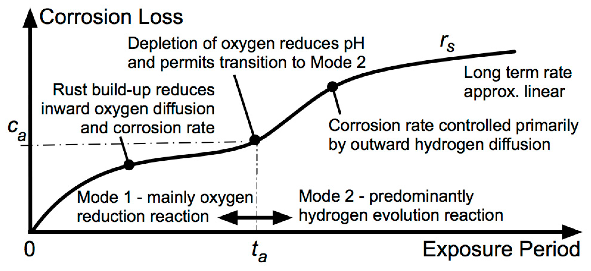
4. Development of Corrosion and Pitting with Continued Exposure

The above discussion focuses on the initiation of corrosion, either through influences on and closely within the steel surface, within the medium and its contact with the steel, or both. In both cases, localized inclusions, defects, imperfections and other mechanisms are important for setting up localized differences in electrochemical potential, and thus, for the initiation of localized corrosion. For practical purposes, the question that then arises is how corrosion initiation from these mechanisms develops into more serious corrosion under extended exposures.
For a variety of metals and alloys and a range of exposure environments, it was demonstrated, using field and laboratory data, that corrosion in general and also corrosion pitting both develop according to the so-called bi-modal trend [63] (Figure 11). This trend applies to metals and alloys for which both the cathodic oxygen reduction reaction (ORR) and the cathodic hydrogen evolution reaction (HER) are thermodynamically feasible.
In the bi-modal model, corrosion commences in phase 1 of mode 1, with the principal reaction being the oxygen reduction reaction (ORR) and the rate controlled by the diffusion of oxygen out of the water (concentration control), but by the time phase 2 is reached, the corrosion is rate-controlled by the inward diffusion rate of oxygen from the available water through the corrosion product layer. This rate declines as the corrosion products build up and decrease in permeability with increasing corrosion, noting that the permeability of rust layers is mainly controlled by the presence and thickness of a magnetite layer in the corrosion product layer [64]. The externally visible FeOOH-type corrosion products are relatively permeable and have much less influence. The reduced availability of oxygen leads to lower pH and increased pitting at the interface, and these then allow mode 2 to take over [65]. The principal corrosion reaction in mode 2 is the hydrogen evolution reaction (HER) that operates only under acidic conditions, but the actual rate of corrosion is controlled by the rate of outward gaseous hydrogen diffusion through the increasing thickness of the rust layers. Eventually, with further development of the rust layers and some potential oxidation of their outer layers [66], an almost steady-state long-term corrosion rate rs will be reached (Figure 11).
The influence of the condition of the metal surface on corrosion loss is reflected by the parameter ca (Figure 11). It represents the corrosion loss at the end of mode 1. Some of this carries through to subsequent corrosion into phase 3, which itself may be under the influence of similar factors. The overall effect for longer-term corrosion is indicated, somewhat indirectly, by the parameter cs (Figure 11). For steels exposed to seawater, the values of ca are available as a function of the seawater mean temperature T, and for seawaters with various concentrations of dissolved inorganic nitrogen (DIN) [67], which is a critical nutrient for microbiologically influenced corrosion (MIC). These and other effects were summarized elsewhere [63].
Turning now to the influence of continued exposure for a system consisting of (a non-perfect) steel with an adjacent non-homogeneous medium of the types outlined above, the question arises regarding how the various local imperfections and impurities affect longer-term corrosion. This can be illustrated with the example of steel reinforcing bars with the surrounding concrete as the medium. When exposed to seawater, the combined effect of local corrosion in one or more (wet) air voids (Figure 9b) on overall corrosion behaviour is shown in Figure 12 [68]. It shows that there is increased early corrosion with larger air voids but also that the corrosion rate then declines very considerably. The latter is the direct result of (near-)exhaustion of the oxygen in the air voids in the medium (concrete) next to the metal surface. The overall, approximately linear, trend is indicated as rate rs, also using the parameter cs obtained via the backprojection of the longer-term rate rs. The bi-modal trend component is shown in each case as conservatively linearized, as shown in the early stages of longer-term corrosion. Figure 12 also shows that after ti, the trend for reinforcement corrosion is initially bi-modal and then reverts for extended exposures to mode 2 (cf. Figure 11). This is the long-term reinforcement corrosion trend that is relevant for high-quality well-compacted concretes.
The long-term trend in Figure 12 is specifically for reinforced concrete exposed to seawater. The overall trend includes a portion (0–ti) to allow for the time it takes for chlorides to diffuse sufficiently far into the concrete to allow for chloride-aided corrosion to occur within the air voids (see above). For corrosion in freshwaters, 0–ti → ∞ since to lower the pH in the concrete adjacent to the steel bars sufficiently, extensive (and usually long-term) leaching of local calcium hydroxide is required. On the other hand, for soils, for which the pH is usually low to neutral, 0–ti → 0, implying that corrosion in the air voids can commence almost immediately if sufficiently wet conditions prevail, with sufficient aeration to allow mode 1 to occur to gradually lower the interfacial pH sufficiently for the HER reaction to be possible and for mode 2 to develop. A classic example for which this development does not occur is that of steel piles driven into marine sands in seawater. For these, no corrosion has been observed, even after many years of exposure, for the part of the pile completely in sand [69].

5. Long-Term Corrosion

As corrosion progresses after ti (Figure 12), the build-up of the corrosion product layer occurs between the steel surface and the medium. This build-up of corrosion product renders the precise condition of the (already corroded) steel surface and that of the medium surface increasingly less relevant as corrosion progresses. Since long-term corrosion relies primarily on the rate of outward diffusion of hydrogen generated by the HER (i.e., as in mode 2, Figure 11), it follows that the factor of most importance for long-term corrosion is the permeability and thickness of the rust layers, together with the permeability and thickness of the medium (as a finite-thickness layer). This is consistent with observations from practical experience that show that for high-permeability media, the long-term corrosion rate rs is higher than for low-permeability media, with rs → 0 as the permeability approaches zero (Figure 12). This applies both to reinforced concrete and to soils of various types.
The right-hand side of Figure 12 shows that for extended exposures, it is possible for the deterioration of the medium to permit reinforcement corrosion. For reinforced concrete, for example, such deterioration can be brought about by the (slow, long-term) action of chlorides on the calcium hydroxide component of the concrete matrix [70], resulting in the loss and leaching out of ferrous chlorides, as seen, for example, at poorly made construction joints after many decades of ‘at sea’ marine exposures [71]. Long-term deterioration of the concrete itself, and its consequential inability to provide effective ‘cover’ protection to the steel reinforcement, can also be caused by alkali–aggregate reactivity within the concrete. This is a much-overlooked deterioration mechanism [72]. All in all, a holistic perspective based on a sound understanding of the possibilities involved and the need to meet corrosion science principles is necessary [73].
On the basis that interface conditions important for initiation are much less relevant for the rate of long-term corrosion, it might be expected that there would be a high degree of consistency for rs across various metal–media combinations for similar media properties. Indeed, for metals (not just steels) immersed in seawater, the long-term rate rs is remarkably consistent at around 2.7 mil/y (0.07 mm/y) for seawaters in the 27 °C temperature range. This also applies to the long-term rate of pit depth progression [74]. Similarly, at around 20 °C, the rate is about 0.06 mm/y, and typical rates for other mean seawater temperatures are available [67], also with allowance for the effect of DIN, although this mainly affects cs. For steels in concrete and steel enclosed with calcareous deposition, the long-term rate is around 0.016–0.018 mm/y, although cs greatly increases with less good compaction of the concrete. For steels and cast irons in soils, the situation is somewhat more complicated since allowance typically must be made for the ‘time of wetness’ in estimating rs [68]. However, for a given geographical region with similar rainfall and assumed similar workmanship in pipe-laying and soil compaction, there is remarkable consistency in rs irrespective of the soil type. In all cases, the long-term corrosion behaviour follows the pattern sketched in Figure 12 (but without the deterioration of the medium).

6. Discussion

The observation that apart from some highly corrosion-resistant ferrous alloys, the long-term corrosion rate rs does not depend much on the ferrous metal type or composition follows from the mechanisms involved in the longer-term corrosion, namely, the HER associated with the essentially steady-state conditions of phase 4 (Figure 11). The rate rs is determined largely by the diffusion properties of the rust layers and of the medium surrounding them (if any) for gaseous hydrogen diffusion emanating from the HER as the cathodic reaction. This does not depend in any significant way on the properties of the steel as the electron donor. However, for other alloys, with corrosion products that are more or less permeable than those for steels, the long-term corrosion rate rs can be expected to be lower or greater, respectively, as is indeed evident even in the unprocessed data in data sources such as Southwell et al. [74].
The notion that voids in the medium immediately adjacent to the metal can be a source for localized corrosion has a long but rather unrecognized history that is not immediately evident from the extensive literature dealing with the corrosion of metals in contact with soils [36,40,41] or from the extensive literature dealing with the initiation of reinforcement corrosion. As noted, already in 1930, a theory based on the fledgling notion of differential aeration was presented to explain the effect of sand particle spacing on localized immersion corrosion for a lead sheet in contact with sand grains [47], but how this developed into longer-term corrosion, as observed on the field-exposures, was not considered. Similarly, but at the micro-scale, the initiation of localized corrosion as a result of a ‘cavity’ in an atomic structure with ‘atoms’ moving out of the metal was described by Evans [12] (p. 48), but subsequent corrosion development was not discussed.
As can be seen from Figure 12, imperfections, inclusions, etc., have the most effect on the parameter cs, which parameterizes the relatively early corrosion behaviour. They have a lesser and decreasing effect on corrosion for extended exposures. The long-term corrosion process is unlikely to be sensitive to inclusions and imperfections in the metal or inhomogeneities in a medium, largely because, as noted above, the development of the rust layer forms what might be described as a ‘blanket’ between the respective non-uniformities. This obviously applies only where the medium is sufficiently accommodating to cope with the physical deformation likely to result from the expansion of the rust layer, which is a scenario often associated with damage to reinforced concrete structures and typically results in concrete cracking and concrete spalling, followed by exposure of the steel to the environment. It follows that the long-term rate of corrosion rs will be relevant only provided there are no changes in the environment provided by the medium (or by the external environment). If such changes do occur, rs may be seriously affected. One example of this occurs for long exposures of reinforced concrete through the outward leaching of the calcium hydroxide component of the concrete, which is accelerated by the presence of chlorides and leaves behind a rather permeable concrete matrix structure that is easily entered by dissolved or atmospheric oxygen, and thus, permits serious reinforcement corrosion [70,75]. A similar problem was noted for deep concrete cracks (see above). For protective coatings, deterioration of that medium itself, through UV radiation or other mechanisms, is also likely to greatly increase rs.
If cracks through the medium to the steel can be kept under control, and if the deterioration of the medium can also be kept under control (e.g., deterioration of protective coatings by UV radiation, leaching of calcium hydroxide from concrete), it should, in principle, be possible to reduce the corrosion under media to near zero for extended periods. This possibility is shown schematically by a very low (blue) trend line in Figure 12. This implies a very low degree of permeability in the medium enclosing the steel, with associated negligible air voids in that medium at the interface. To be clear, in the ideal case, the latter implies that there will be no transition from mode 1 to mode 2 (Figure 11), as the lack of oxygen does not permit the local pH at the interface to lower sufficiently for the HER to take over from ORR [65]. As is also clear from Figure 12, with some permeability of the medium, there will be some corrosion in mode 1 under oxygen conditions, and as these become exhausted or the rate of inward diffusion becomes insufficient, the pH at the interface will reduce and pitting will increase, thereby permitting the transition from mode 1 to mode 2. It follows that the longer-term corrosion rate rs will be under cathodic HER conditions with the long-term corrosion rate governed by the diffusion rate through the medium of gaseous hydrogen, as generated by the HER.
The practical implications of the above observations are considerable. They arose originally from puzzling aspects of the long-term durability of some reinforced concretes when conventional thinking would lead to reinforcement corrosion, but that was not observed [46,52]. Similarly, they arose from observations of cast iron pipes buried in soils that showed no evidence of corrosion despite conventional wisdom indicating that they should have high degrees of corrosion, even though they were all in soils with pHs around neutral. The direct implication of the latter observations is that the conventional thinking that the high alkalinity of the concrete was the reason for the protection of the steel in reinforced concrete cannot be sustained. There is little difference between a steel bar buried well inside concrete and a cast iron pipe buried deep in soil. It can now be seen that the driver for the aggressive corrosion sometimes (nay, often) seen in practice is the direct result of problems at the interface—poor contact due to poor compaction or, equivalently, too high a degree of permeability (and porosity) within the matrix of the medium and in particular at the interface. This destroys the long-standing conventional wisdom that it is the alkaline layer around a reinforcement bar that offers protection against corrosion—this may be the case sometimes, but more generally, it is the interfacial condition that is the important criterion. Without good contact all around, even the presence of high alkalinity is not sufficient. From this, it follows immediately that the cement content in concrete, while very important for concrete strength, has little to do with long-term reinforcement durability. On the other hand, adding more water to the concrete, which is much discouraged because it lowers the concrete strength (and increases permeability), does increase the workability of the concrete, thereby increasing the probability of a high degree of interfacial contact between the hardened concrete and the steel bars (assuming the concrete shrinkage is not significant). It is evident that these derived conclusions are almost diametrically opposite to conventional thinking. Yet the implications are potentially far-reaching. They indicate that irrespective of the binder used for ‘concretes’, the advantage of using a high-strength and high-elastic-modulus material, such as steel, for reinforcement is completely acceptable from a durability perspective provided sufficient attention is given to achieving a high degree of interfacial contact. And, of course, provided the concrete cover is sufficient in thickness and impermeability to obviate oxygen diffusion issues.
For ferrous pipes buried in soil, too, the recent observations and deductions about the role of interfacial contact have cast a new light on what is important and what is not [42] in the process by-passing much of the impasse voiced (at least in print) by many investigators over many years [41]. By idealizing the corrosion scenario with metal and an adjacent medium in the manner used above, it should be clear that systems such as protective coatings over metals, insulting materials over and around steel or other pipes or fittings, or layers of marine growth over steels have direct parallels to the observations given herein. No doubt further investigations will be required to characterize and enumerate the detailed behaviours, but the trends and patterns should be similar—the degree of interfacial contact governing early corrosion (as in ci, Figure 12) and with the permeability of the medium much influencing the rate of long-term corrosion rs.
The above exposition does not consider cases where the medium has a significant degree of electrical conductivity. It is likely that contact issues will be involved if not overshadowed by galvanic corrosion development. This remains a topic for further investigation.
From an environmental and energy point of view, there are significant advantages in extending the likely lifetime of infrastructure, such as reinforced concrete structures and buried ferrous pipes. Contrary to commercial pressures, it can now be seen that there is no need for alternative materials of unknown long-term durability provided proper care is taken in infrastructure specification and in construction (and in supervision) to achieve the requirements now evident for achieving long-term durability. This, in fact, should not come as a surprise to those with long-standing deep interests in their industry, but to date, the evidence has been anecdotal at best.
At a more philosophical level, there is a tendency to sometimes ‘dismiss’ or consider as ‘aberrations’ any observations that do not fit the conventional wisdom at any given time. As noted above, an extreme example was the outright rejection by von Wolzogen Kuhr and van der Vlugt [40] of the report by Wicher [43] that cast iron pipes well buried in clay soils can last many decades. This is unfortunate, since as noted many years ago [76], such an observation(s) may disprove the current theories. Objectively considered, they also may spur further and likely more detailed investigations and eventually allow a new or different light to be cast on the currently available knowledge.

7. Conclusions

The following conclusions may be drawn from the interpretations presented herein:
  • Both local differences in electrochemical potential due to inhomogeneities of the steel and inhomogeneities of the surface of the medium interfacing with the steel can be sources of initiation of corrosion for the steel, although, for many practical applications, the inhomogeneities of the medium are of greater importance due to their greater physical scale.
  • Corrosion of steel in water and the atmosphere may be considered specialized cases of corrosion in homogeneous media extending over semi-infinite spaces.
  • As corrosion at the interface progresses, the instantaneous corrosion rate is increasingly governed by the properties of the corrosion products at the interface and less by the properties of the steel or the medium, with corrosion progressing eventually to and then through the hydrogen evolution as the principal long-term cathodic reaction in all cases.
  • The same mechanisms are likely to hold for other media of types similar to those considered herein when in contact with alloys and metals other than steel and for which the hydrogen evolution reaction is feasible.
  • Breakdown of the medium itself may lead to steel corrosion—it is not always the case that the corrosion of the steel causes damage to, and possibly breakdown of, the medium.

Funding

This research was funded by the Australian Research Council (grants DP0771695, DP1093787, DP170103737).

Acknowledgments

The financial support of several organizations for projects that have contributed to the material presented herein is gratefully acknowledged. These include, principally, the Australian Research Council and Sydney Water and Hunter Water Corporations. In addition, the research support of Robert Jeffrey, Igor Chaves and Robert Petersen of the University of Newcastle is much appreciated, as are useful discussions with many practitioners, particularly Norwood Harrison, who was for many years a concrete technologist with concrete pipe manufacturer Humes and Warren Green of Vinsi Partners, Newcastle.

Conflicts of Interest

The author declare no conflicts of interest.

References

  1. Ackland, B.G.; Dylejko, K.P. Critical questions and answers about cathodic protection. Corros. Eng. Sci. Technol. 2019, 54, 688–697. [Google Scholar] [CrossRef]
  2. Coogan, C. Marine Corrosion and Cathodic Protection; CRC Press: Boca Raton, FL, USA, 2022. [Google Scholar]
  3. Jones, D.A. Principles and Prevention of Corrosion, 2nd ed.; Prentice Hall: Upper Saddle River, NJ, USA, 1996. [Google Scholar]
  4. Garrels, R.M.; Christ, C.L. Solutions, Minerals and Equilibria; Harper & Row: New York, NY, USA, 1965. [Google Scholar]
  5. Pourbaix, M. Atlas of Electrochemical Equilibria in Aqueous Solutions; NACE Int.: Houston, TX, USA, 1974. [Google Scholar]
  6. Mercer, A.D.; Lumbard, E.A. Corrosion of mild steel in water. Br. Corros. J. 1995, 30, 43–55. [Google Scholar] [CrossRef]
  7. Abiko, K.; Nakajima, T.; Harima, N.; Takaki, S. Preparation of 10 kg ingot of ultra-pure iron. Phys. Status Solidi 1998, 167, 347–355. [Google Scholar] [CrossRef]
  8. Abiko, K. Why do we study ultra-pure base metals? Mater. Trans. JIM 2000, 41, 233–237. [Google Scholar] [CrossRef]
  9. Khan, L.; Sato, K.; Okuyama, S.; Kobayashi, T.; Ohashi, K.; Hirasaka, K.; Nikawa, T.; Takada, K.; Higashitani, A.; Abiko, K. Ultra-high purity iron is a novel and very compatible biomaterial. J. Mech. Behav. Biomed. Mater. 2020, 106, 103744. [Google Scholar] [CrossRef] [PubMed]
  10. Ferrara, E.; Olivetti, E.; Fiorillo, F.; Forton, R.; Martino, L.; Rocchino, L. Microstructure and magnetic properties of pure iron for cyclotron electromagnets. J. Alloys Compd. 2014, 615, S291–S295. [Google Scholar] [CrossRef]
  11. Li, S.; Hihara, L.H. The comparison of the corrosion of ultrapure iron and low-carbon steel under NaCl-electrolyte droplets. Corros. Sci. 2016, 108, 200–204. [Google Scholar] [CrossRef]
  12. Evans, U.R. The Corrosion and Oxidation of Metals: Scientific Principles and Practical Applications; Edward Arnold: London, UK, 1960. [Google Scholar]
  13. Atrens, A.; Song, G.-L.; Cao, F.; Shi, Z.; Bowen, P.K. Advances in Mg corrosion and research suggestions. J. Magnes. Alloys 2013, 1, 177–200. [Google Scholar] [CrossRef]
  14. van der Voort, G.F. Metallurgy: Principles and Practice; McGraw-Hill: New York, NY, USA, 1984. [Google Scholar]
  15. Wranglen, G. Review article on the influence of sulphide inclusions on the corrodibility of Fe and steel. Corros. Sci. 1969, 9, 585–602. [Google Scholar] [CrossRef]
  16. Wranglen, G. Pitting and sulphide inclusions in steel. Corros. Sci. 1974, 14, 331–349. [Google Scholar] [CrossRef]
  17. Lillard, R.S.; Kashfipour, M.A.; Niu, W. Pit propagation at the boundary between manganese sulfide inclusions and austenitic stainless steel 303 and the role of copper. J. Electro. Soc. 2016, 163, C440–C451. [Google Scholar] [CrossRef]
  18. Melchers, R.E.; Chaves, I.A.; Jeffrey, R. A conceptual model for the interaction between carbon content and manganese sulphide inclusions in the short-term seawater corrosion of low carbon steel. Metals 2016, 6, 132. [Google Scholar] [CrossRef]
  19. King, R.A.; Miller, J.D.A. Corrosion by the sulphate-reducing bacteria. Nature 1971, 233, 491–492. [Google Scholar] [CrossRef] [PubMed]
  20. Crolet, J.-L. From biology and corrosion to biocorrosion. In Microbial Corrosion; Sequeira, C.A., Tiller, A.K., Eds.; The Institute of Metals: London, UK, 1992; pp. 50–60. [Google Scholar]
  21. Jia, R.; Unsal, T.; Xu, D.; Lekbach, X.; Gu, T. Microbiologically infleucned corroison and current mitigation strategies: A state of the art review. Int. Biodeterior. Biodegrad. 2019, 137, 42–58. [Google Scholar] [CrossRef]
  22. Melchers, R.E.; Jeffrey, R. Surface roughness effect on marine immersion corrosion of mild steel. Corrosion 2004, 60, 697–703. [Google Scholar] [CrossRef]
  23. Melchers, R.E.; Ahammed, M.; Jeffrey, R.J.; Simundic, G. Statistical characterization of corroded steel surfaces. Mar. Struct. 2010, 23, 274–287. [Google Scholar] [CrossRef]
  24. Phull, B.S.; Pikul, S.J.; Kain, R.M. Seawater corrosivity around the world: Results from five years of testing. In Corrosion Testing in Natural Waters, Second Volume; Kain, R.M., Young, W.T., Eds.; STP1300; American Society for Testing and Materials: West Conshohocken, PA, USA, 1997; pp. 34–73. [Google Scholar]
  25. Burstein, G.T.; Pistorius, P.C.; Mattin, S.P. The nucleation and growth of corrosion pits on stainless steels. Corros. Sci. 1993, 35, 57–62. [Google Scholar] [CrossRef]
  26. Foley, R.T. Role of the chloride ion in iron corrosion. Corrosion 1970, 26, 58–70. [Google Scholar] [CrossRef]
  27. Foley, R.T. Complex ions and corrosion. J. Electrochem. Soc. 1975, 11, 1493–1994. [Google Scholar] [CrossRef]
  28. Heyn, E.; Bauer, O. Ueber den Angriff des Eisens durch Wasser und wässerige Losungen. Stahl. Eisen 1908, 28, 1564–1573. [Google Scholar]
  29. Brasher, D. Stability of the oxide film on metals in relation to inhibition of corrosion. I. Mild steel in the presence of aggressive ions. Brit. Corr. J. 1967, 2, 95–103. [Google Scholar] [CrossRef]
  30. Baylis, J.R. Factors other than dissolved oxygen influencing the corrosion of iron pipes. Ind. Engrg. Chem. 1926, 18, 370–380. [Google Scholar] [CrossRef]
  31. Little, B.J.; Gerke, T.L.; Lee, J.S. Mini-review: The morphology, mineralogy and microbiology of accumulated iron corrosion products. Biofouling 2014, 30, 941–948. [Google Scholar] [CrossRef]
  32. Greene, N.D.; Fontana, M.G. A critical analysis of pitting corrosion. Corrosion 1959, 15, 41–47. [Google Scholar] [CrossRef]
  33. Sharland, S.M.; Tasker, P.W. A mathematical model of crevice and pitting corrosion—I. The physical model. Corros. Sci. 1988, 28, 603–620. [Google Scholar] [CrossRef]
  34. Butler, G.; Stretton, P.; Beynon, J.G. Initiation and growth of pits on high-purity iron and its alloys with chromium and copper in neutral chloride solutions. Br. Corros. J. 1972, 7, 168–173. [Google Scholar] [CrossRef]
  35. Pourbaix, M. Significance of protection potential in pitting and intergranular corrosion. Corrosion 1970, 26, 31–438. [Google Scholar] [CrossRef]
  36. Romanoff, M. Underground Corrosion, National Bureau of Standards Circular 579; US Government Printing Office: Washington, DC, USA, 1957.
  37. Rajani, B.; Kleiner, Y. Comprehensive review of structural deterioration of water mains: Physically based models. Urban. Water 2001, 3, 151–164. [Google Scholar] [CrossRef]
  38. Cole, I.S.; Marney, D. The science of pipe corrosion: A review of the literature on the corrosion of ferrous metals in soils. Corros. Sci. 2012, 56, 5–16. [Google Scholar] [CrossRef]
  39. Kleiner, Y.; Rajani, B.; Krys, D. Performance of ductile iron pipes. I: Characterization of exterior corrosion patterns. J. Infrastruct. Syst. ASCE 2013, 19, 108–119. [Google Scholar] [CrossRef]
  40. von Wolzogen Kuhr, C.A.H.; van der Vlugt, L.S. Graphitization of cast iron as an electrochemical process in anaerobic soils, Water (den Haag), 18: 147–165 (in Dutch). Transl. Corros. 1971 1934, 17, 293–299. [Google Scholar]
  41. Ricker, R.E. Analysis of pipeline steel corrosion data from NBS (NIST) studies conducted between 1922–1940 and relevance to pipeline management. J. Res. Nat. Inst. Stand. Technol. 2011, 115, 373–392. [Google Scholar] [CrossRef]
  42. Melchers, R.E. Models for prediction of long-term corrosion of cast iron water mains. Corrosion 2020, 76, 441–450. [Google Scholar] [CrossRef] [PubMed]
  43. Wichers, C.M. Korrosion asphaltierter eiserner Rohre. Das. Gas. Wasserfach 1934, 77, 131–132. [Google Scholar]
  44. Liengen, T.; Feron, D.; Basseguy, R.; Beech, I.B. (Eds.) Understanding Biocorrosion, European Federation of Corrosion Publications; Number 66; Woodhead Publishing in Materials: Cambridge, UK, 2014. [Google Scholar]
  45. Skovhus, T.L.; Eckert, R.B. (Eds.) Failure Analysis of Microbiologically Influenced Corrosion; CRC Press: Boca Raton, FL, USA, 2021. [Google Scholar]
  46. Melchers, R.E.; Chaves, I.A. A comparative study of chlorides and longer-term reinforcement corrosion. Mater. Corros. 2017, 68, 613–621. [Google Scholar] [CrossRef]
  47. Burns, M.; Salley, D.J. Particle size as a factor in the corrosion of lead by soils. Ind. Eng. Chem. 1930, 22, 293–297. [Google Scholar] [CrossRef]
  48. Petersen, R.B.; Melchers, R.E. Pitting corrosion of mild steel in long-term contact with particulate media in seawater. Corrosion 2023, 79, 1040–1061. [Google Scholar] [CrossRef] [PubMed]
  49. Richardson, M.G. Fundamentals of Durable Reinforced Concrete; Spon Press: London, UK, 2002. [Google Scholar]
  50. Angst, U.M.; Geiker, M.R.; Michel, A.; Gehlen, C.; Wong, H.; Isgor, O.B.; Elsener, B.; Hansson, C.M.; François, R.; Hornbostel, K.; et al. The steel-concrete interface. Mater. Struct. 2017, 50, 1–24. [Google Scholar] [CrossRef]
  51. Wakeman, C.M.; Dockweiler, E.V.; Stover, H.E.; Whiteneck, L.L. Use of concrete in marine environments. Proc. ACI 1958, 54, 841–856. [Google Scholar]
  52. Melchers, R.E.; Li, C.Q. Reinforcement corrosion initiation and activation times in concrete structures exposed to severe marine environments. Cem. Concr. Res. 2009, 39, 1068–1076. [Google Scholar] [CrossRef]
  53. Angst, U.M.; Elsener, B.; Larsen, C.K.; Vennesland, O. Critical chloride content in reinforced concrete—A review. Cem. Concr. Res. 2009, 39, 1122–1138. [Google Scholar] [CrossRef]
  54. Nawy, E.G. Concrete Construction Engineering Handbook; CRC Press: Boca Raton, FL, USA, 2008; pp. 30–57. [Google Scholar]
  55. Page, C.L. Mechanism of corrosion protection in reinforced concrete marine structures. Nature 1975, 258, 514–515. [Google Scholar] [CrossRef]
  56. Lea, F.M.; Hewlett, P.C. Lea’s Chemistry of Cement and Concrete, 4th ed.; Butterworth Heinemann: London, UK, 1997. [Google Scholar]
  57. Johnston, J.; Grove, C. The solubility of calcium hydroxide in aqueous salt solutions. J. Am. Chem. Soc. 1931, 53, 3976–3991. [Google Scholar] [CrossRef]
  58. Cornell, R.M.; Schwertmann, U. The Iron Oxides: Structure, Properties, Reactions, Occurences and Uses, 2nd ed.; VCH Publishers: Weinheim, Germany, 1996. [Google Scholar]
  59. Melchers, R.E.; Li, C.Q.; Davison, M.A. Observations and analysis of a 63-year old reinforced concrete promenade railing exposed to the North Sea. Mag. Concr. Res. 2009, 61, 233–243. [Google Scholar] [CrossRef]
  60. Berensen, A.M. Marine Painting Manual; Springer-Science & Business Media BV: Dordrecht, The Netherlands, 1989. [Google Scholar]
  61. Hare, C.H. Corrosion Control of Steel by Organic Coatings; Revie, R.W., Ed.; Wiley: New York, NY, USA, 2011; pp. 971–983. [Google Scholar] [CrossRef]
  62. TSCF. Condition Evaluation and Maintenance of Tanker Structures; Tanker Structures Cooperative Forum, Witherby & Co.: London, UK, 1992; p. 182. [Google Scholar]
  63. Melchers, R.E. A review of trends for corrosion loss and pit depth in longer-term exposures. Corros. Mater. Degrad. 2018, 1, 4. [Google Scholar] [CrossRef]
  64. Refait, P.H.; Grolleau, A.-M.; Jeannin, M.; Rémazeilles, C.; Sabot, R. Corrosion of carbon steel in marine environments: Role of the corrosionproduct layer. Corros. Mater. Degrad. 2020, 1, 198–218. [Google Scholar] [CrossRef]
  65. Melchers, R.E.; Jeffrey, R. The transition from short- to long-term marine corrosion of mild steel—1. experimental observations—2. parameterization and modeling. Corrosion 2022, 78, 415–436. [Google Scholar] [CrossRef]
  66. Stratmann, M.; Bohnenkamp, K.; Engell, H.J. An electrochemical study of phase-transitions in rust layers. Corros. Sci. 1983, 23, 969–985. [Google Scholar] [CrossRef]
  67. Melchers, R.E. Long-term immersion corrosion of steels in seawaters with elevated nutrient concentration. Corros. Sci. 2014, 81, 110–116. [Google Scholar] [CrossRef]
  68. Melchers, R.E. Long-term durability of marine reinforced concrete structures. J. Mar. Sci. Eng. 2020, 8, 290. [Google Scholar] [CrossRef]
  69. Morley, J. The corrosion and protection of steel-piled structures. Struct. Surv. 1993, 7, 138–151. [Google Scholar] [CrossRef]
  70. Melchers, R.E.; Chaves, I.A. Reinforcement corrosion in marine concretes—2. Long-term effects. ACI Mater. J. 2020, 117, 217–228. [Google Scholar]
  71. Melchers, R.E.; Howlett, C.M. Reinforcement corrosion of the Phoenix caissons after 75 years of marine exposure. Proc. Inst. Civ. Eng.-Marit. Eng. 2020, 174, 19–30. [Google Scholar] [CrossRef]
  72. Melchers, R.E.; Humphrey, H. Concrete alkali-aggregate reactivity and initiation of steel reinforcement corrosion. Corros. Mater. Degrad. 2023, 4, 428–444. [Google Scholar] [CrossRef]
  73. Melchers, R.E. Mechanisms in long-term marine corrosion of steel reinforcement in concrete. Corrosion 2023, 79, 380–387. [Google Scholar] [CrossRef] [PubMed]
  74. Southwell, C.R.; Bultman, J.D.; Alexander, A.L. Corrosion of metals in Tropical environments—Final report of 16 years exposures. Mater. Perform. 1976, 15, 9–25. [Google Scholar]
  75. Melchers, R.E.; Chaves, I.A. Reinforcement corrosion in marine concretes—1: Initiation. ACI Mater. J. 2019, 116, 57–66. [Google Scholar] [CrossRef]
  76. Popper, K.R. The Growth of Scientific Knowledge; Basic Books: New York, NY, USA, 1963. [Google Scholar]
Figure 1. Perfect metal and perfect medium with H2O and O2 available: (a) physical-chemical reaction with direct electron transfer at interface and (b) electrochemical reaction set up by imperfect corrosion products, potential perturbation(s) ΔE, and electron flow between anode and cathode.
Cmd 05 00003 g001
Figure 2. Data points and trending for the effect of increasing roughness (imperfections) of metal surface on corrosion loss soon after first exposure and subsequent periods of exposure (based on Melchers & Jeffrey 2004 [22]).
Cmd 05 00003 g002
Figure 3. Commercial rolled mild steel exposed to natural seawater for 13 months in 20 °C natural seawater showing widespread pitting and a small proportion of the area that could be assigned as cathodic zones (scale: vertical side ≈ 10 mm).
Cmd 05 00003 g003
Figure 4. Relatively rare example of near-idealized circular cathodic region around the pit (centre) overlying corroded and pitted steel surface. Note: the saw-cuts across the 50 mm wide steel strips were made after exposure for mass loss estimates.
Cmd 05 00003 g004
Figure 5. Schematic view of imperfect medium with voids, inclusions and delamination (non-contact regions) showing differential potentials.
Cmd 05 00003 g005
Figure 6. Localized corrosion predominantly on the undersides of cast iron pipe (900 mm dia., 100+ -year-old, 1.2 m depth) in sandy loam soil.
Cmd 05 00003 g006
Figure 7. Conceptual model for localized corrosion of steel or cast iron in soil at a wet air void [42], which is also applicable to steel in high-quality concrete with air voids present at the interface.
Cmd 05 00003 g007
Figure 8. (a) Cross-section of steel reinforcement bar (6 mm dia.) in concrete air voids in the concrete matrix and the localized corrosion opposite wet air voids in the concrete (circled) at the interface between steel and concrete and (b) a (typical) steel reinforcement bar (6 mm dia.) showing mostly corrosion along the bottom of the bar after recovery from good quality concrete.
Cmd 05 00003 g008
Figure 9. Examples of severe localized loss of reinforcement steel from (a) corrosion inside through wall cracking of 40-year-old Sydney Harbour ammunition lighters showing the typical red-brown corrosion stains left by oxidation of ferrous chloride and (b) example of highly localized corrosion of reinforcement steel (6 mm dia.) at a location coinciding with a crack from the external wet saline environment.
Cmd 05 00003 g009
Figure 10. Example of watery-looking rust stains that resulted from oxidation of water-soluble ferrous chlorides formed in deep defects and cracking in the protective coating.
Cmd 05 00003 g010
Figure 11. Schematic bi-modal corrosion loss trend showing modes 1 and 2, cathodic reactions and corrosion rate controlling diffusion mechanisms. Note the requirement for a drop in pH to permit the cathodic hydrogen evolution reaction to act in mode 2.
Cmd 05 00003 g011
Figure 12. Schematic representation of corrosion loss as a function of exposure period for steel encased in concrete and for steel in soils. For steel in marine concretes, the period 0–ti allows for the inward diffusion of chlorides that may aid corrosion initiation (through pitting) at ti. For soils at around neutral pH, the period 0–ti → 0. For highly impermeable concretes and soils, the transition to mode 2 does not occur and the very low corrosion loss (blue line) is relevant. For more permeable media, the long-term corrosion rate rs increases slightly with permeability.
Cmd 05 00003 g012
Disclaimer/Publisher’s Note: The statements, opinions and data contained in all publications are solely those of the individual author(s) and contributor(s) and not of MDPI and/or the editor(s). MDPI and/or the editor(s) disclaim responsibility for any injury to people or property resulting from any ideas, methods, instructions or products referred to in the content.

