Article

Role of Hydrogen in Metal Oxidation—Implication to Irradiation Enhanced Corrosion of Ni-Based Alloys and Stainless Steels in High Temperature Water

New Industry Creation Hatchery Center, Tohoku University, Sendai 980-8579, Japan
*
Author to whom correspondence should be addressed.
Corros. Mater. Degrad. 2022, 3(2), 281-302; https://doi.org/10.3390/cmd3020017
Submission received: 6 April 2022 / Revised: 11 May 2022 / Accepted: 10 June 2022 / Published: 19 June 2022

Abstract

:
Hydrogen plays various roles in metals or at metal–environment interfaces. Well known effects on metals are hydrogen embrittlement, hydrogen enhanced local plasticity, hydrogen enhanced strain-induced vacancy, hydrogen accelerated oxidation, hydrogen-induced creep, and their synergy. In this study, the potential roles of hydrogen in materials degradation are demonstrated and studied by two different tests. One is the high temperature oxidation of Ni-based alloy in various environments with hydrogen penetration, and the other is the effects of neutron flux/fluence on the oxidation kinetics and SCC of 316L and 316LN stainless steels, regarding a possible role of transmuted H from N. The results emphasize that the hydrogen either permeated into metals from surrounding environments, such as high temperature water or gaseous hydrogen, or generated in metals by nuclei transmutation, such as hydrogen transmuted from N atoms in metals, which can promote metal oxidation through multiple mechanisms. Apparently, the oxidation/corrosion phenomenon is a synergy of sub-mechanisms. For instance, dissolved hydrogen (DH) is usually believed to slow down the corrosion process for lowering the open circuit potential (OCP). However, H also facilitates the transport of the cations in oxide, thereby accelerating the corrosion process. In this bi-mechanism system, two different, contradictory mechanisms work and exist simultaneously. Therefore, whether the metallic materials are benefited or degraded by the H during its oxidation process depends on which sub-mechanism is dominant. Namely, hydrogen can play the role an oxidant in the metal and metal/oxide interface to pre-oxidize metal elements, such as Cr, Ni, and Fe, and possibly promote inward oxygen diffusion and the oxidation rate at the interface. Moreover, hydrogen may play a role as a reductant in oxides where existing oxides can be reduced. Then, the protective capability of oxides will be decreased to result in corrosion acceleration at the metal–oxide interface. These phenomena were observed in Ni-based alloy and possibly austenitic stainless steel containing N such as 316LN SS. This work demonstrates a part of the role of hydrogen on oxidation, and more extensive and systematic work is needed to delineate the role of hydrogen on oxidation with and without irradiation.

1. Introduction

Surface integrity has a significant influence on crack initiation. The steam generator (SG) tube contributes to a substantial percentage of the reactor coolant pressure boundary, which plays an important role on fission product containment as well. In general, the SG tube works as a barrier between the radiative products and the clean environment. Many degradations, such as stress corrosion cracking (SCC), threaten the safe usage of the SG tube. Actually, plenty of old SG tubes were replaced due to the serious damage of the SG tube, which caused a high maintenance cost. Primary water (PW) SCC evolved from laboratory research in 1950s and 1960s to a major degradation mechanism in the 1970s and 1980s. The oxidizing condition causes the increment of the formation and transportation of the corrosion products, the higher radiation fields, crud buildup on fuel, and increases the corrosion of fuel rods as well as the susceptibility of the structural materials to SCC.
As the countermeasure, hydrogen was added into the primary coolant to minimize the radiation field and improve the reactivity control of the reactor. It was indicated that the radiolytic species in-pile as a function of the dissolved hydrogen (DH) level [1]. However, the analysis of the production rate of oxidizing species induced by radiolysis suggested that a DH concentration much less than 15 cc/kg was enough to scavenge the oxidizing species. The DH concentration was suggested to be set at a range of 25–50 cc/kg at the beginning by the Electric Power Research Institute (EPRI), to provide a margin against the oxidizing condition and the operational control. However, evidence from laboratory research proved that an inversely proportional relationship to the DH concentration was found on the time-to-cracking the DH concentration, which increased the susceptibility of the SCC initiation in high temperature water on some SG tubes using Alloy 600 [2,3]. Considering the uncertainties and higher cost for changing the SG tube, it is still suggested to optimize the water chemistry as well as possible. Therefore, lots of researchers preferred to increase the DH value to 50–80 cc/kg for example, providing a sufficient reductive effect to the primary coolant while avoiding the susceptibility of PWSCC. It is well known that H atoms easily penetrate metals due to its small size, particularly at a high temperature. Since the secondary water contains extremely low DH, the increment of DH in primary water will induce the permeation of H from primary to secondary water. This permeated H might induce other degradations on the secondary side of the SG-tube.
On the other hand, despite the H from the high DH concentration, there was a large amount of H up-taken by the materials from the dissociation of the water molecule during the buildup of the passive film (an oxidation process). The SIMS analyses were conducted using isotopically marked pressuring H gas and water, and the results clearly show the contribution of the H absorption from the H in water molecule instead of the pressurized H2 gas [4]. A recent work also demonstrated that the H produced by the corrosion process (dissociated from water molecule) is considered as the main source of the H up-taken after the fatigue test of 316LN stainless steel in hydrogenated high temperature water [5].
Another source of hydrogen in metals is by transmutation, where hydrogen can be generated in materials by a (n, p) reaction. In general, light elements tend to generate more gaseous transmutation elements, such as C, N, and Si. The above evidence and data provide a strong indication that the research on how H interacts with the metal and alloy (Ni-based alloys and stainless steels) used in nuclear power plant is necessary and important, but still not yet sufficient. Therefore, this study provided two interesting topics on (1) the effect of H-permeation on the high temperature oxidation of metallic Ni and Ni-based alloy, and (2) the effects of neutron flux/fluence on the oxidation kinetics and SCC of 316L and 316LN stainless steels, which will be separately introduced as two sections in this paper.

2. Section 1—High Temperature Oxidation of Ni Based Alloy in Various Environments with Hydrogen

The influence of the pre-charged hydrogen on the oxidation behavior in high temperature water have been studied previously [6]. However, one major drawback is that the hydrogen amount charged into the material is limited. Even though the solubility of H in different materials varies, one fact is that the H cannot be replenished once the oxidation test started. The hydrogen amount keeps dropping as the oxidation time increases. To guarantee a sustainable and stable hydrogen charging process, an in-situ hydrogen charging method was used. The configuration of the system is given elsewhere [7,8].

2.1. Experimental

The material used in this research is mill-annealed Alloy 600 (composition in wt.%: C, 0.059, Si, 0.13, Mn, 0.21, Cr, 15.57, Nb, 0.05, Fe, 9.41, S, 0.001, Ti, 0.25, P, 0.006, Cu, 0.12 and, Ni as Bal.) and metallic Ni (composition in wt.%: Co, 0.003, Cu, 0.013, C, 0.014, Fe, 0.016, Mn, 0.24, Si, 0.16, S, 0.001 and, Ni as Bal.). The surface of the materials before oxidation was ground to 4000# grid and then polished until 1 μm. The oxidation test was conducted in air and high temperature water with a water chemistry controlling loop, respectively. The test was carried out in air at a temperature of 800 °C for 10 h. The specimen geometry is a tubular-type specimen with one end covered by a metallic Ni plate. Pure hydrogen gas was charged to the inside of the specimen while the oxidation is taking place at a surface exposed to the air under hydrogen permeation from an inner side. In the meantime, the test in high temperature deionized water was conducted at a temperature of 288 °C for 336 h. The water chemistry was maintained by a recirculation loop system, where DH and dissolved oxygen (DO) values were kept at less than 1 ppb and 2 ppm, respectively.
The morphology of the cross-section of the specimen was observed using scanning electron microscopy (SEM; Hitachi SU70, Hitachi High-Tech Corporation, Hitachi, Japan). Transmission electron microscopy (TEM; JEOL JEM-ARM200F, JEOL Ltd., Tokyo, Japan) was conducted using a 200 kV field emission gun microscope. The TEM sample was prepared using SEM with a focused ion beam (FIB; JEOL JIB-4600F, JEOL Ltd., Tokyo, Japan), with Ga+ as the ion source. The elemental distribution of the cross-section was examined by Auger electron spectroscopy (AES, PHYSICAL ELECTRONICS PHI 680 Auger Nanoprobe, Physical Electronics, Inc., Eden Prairie, MN, USA).

2.2. Results and Discussion

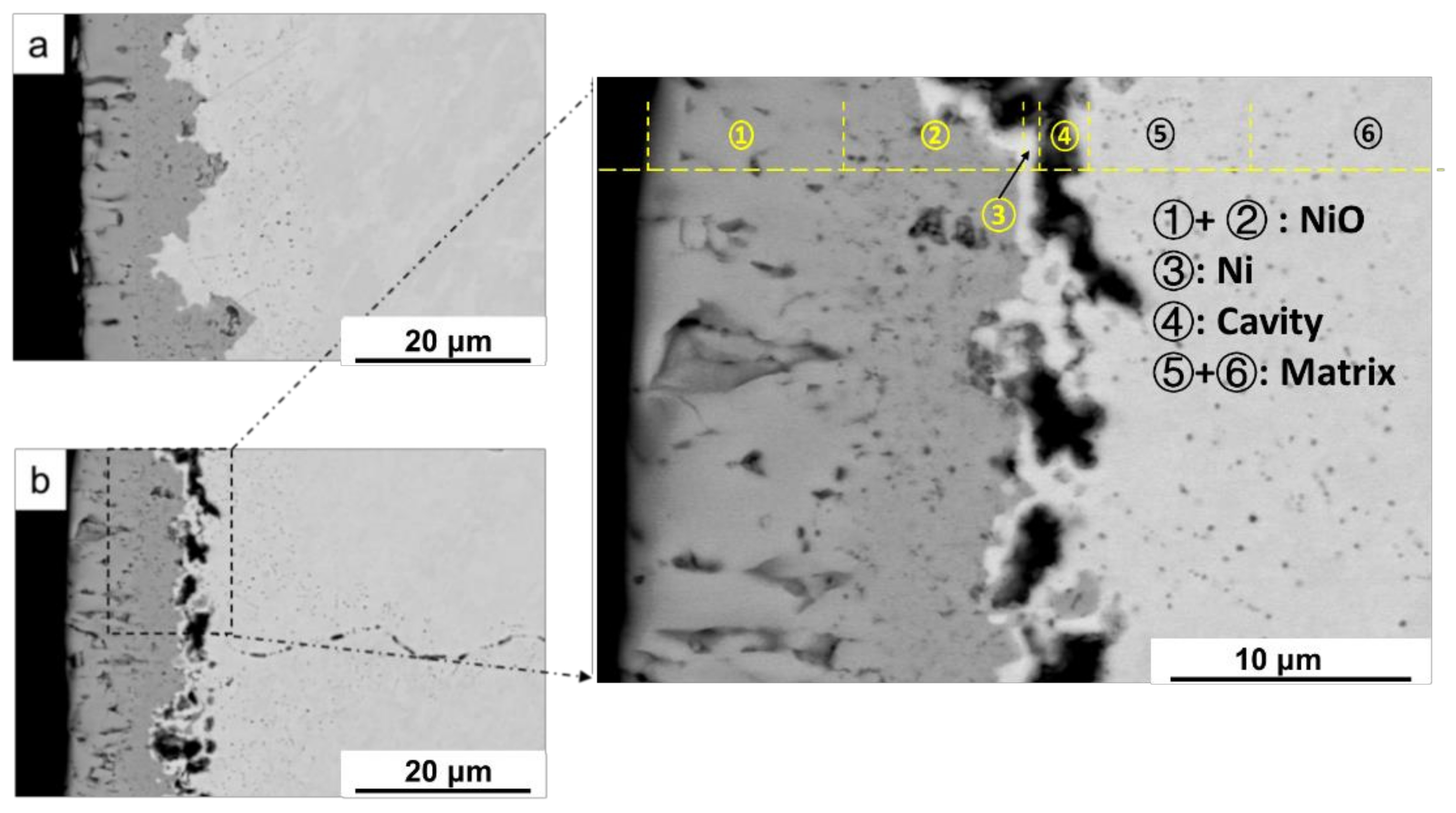
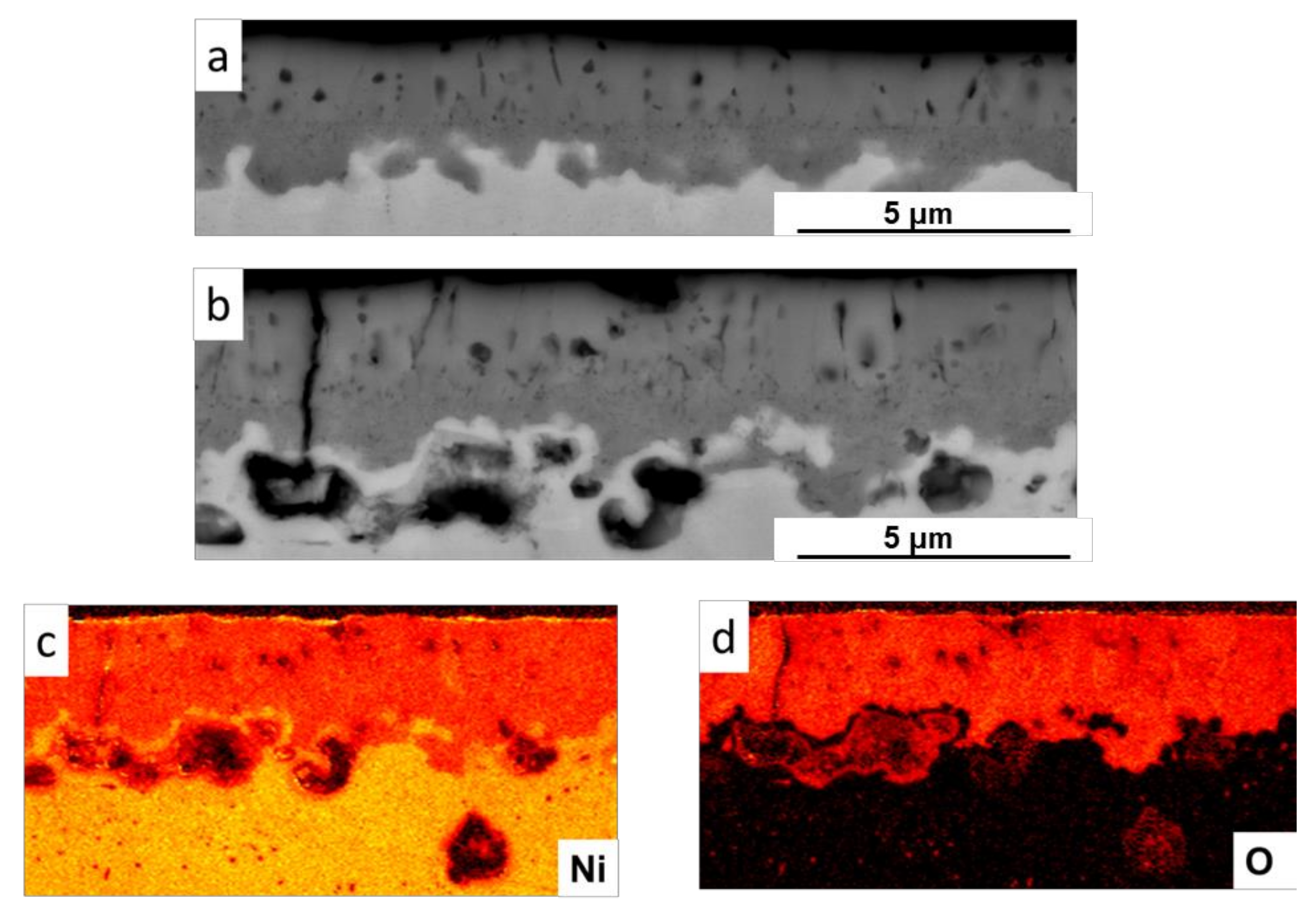
2.2.1. Oxidation Behavior of Metallic Ni with Hydrogen Permeation in Air

Figure 1a,b show the back-scattered electron (BSE) images of the cross-sectional morphologies of the metallic Ni oxidized in Air condition at 800 °C for 10 h with Ar- and H-permeation, respectively. The double-layer structure of the oxide film constituted of the outward dendritic oxide and inward grown oxide can be clearly observed in Figure 1a. The straight interface at the outward/inward oxide layer is the original surface. Comparing with the dendritic oxide layer, the inward grown oxide is rather inhomogeneous in the view of depth. The thickness of the inward-grown oxide can be as great as 10 µm while in other areas less than 5 µm. Considering that the growth of the inward grown oxide largely depends on the inward diffusion of the oxygen atom [9,10], it is reasonable to make an assumption that the oxygen diffusion rate varies at different locations. This may be induced by the grain orientation, dislocation, defects, etc. However, for the H-charged specimen, the original surface is neither clear nor flat compared to that without H. The maximum of the depth of the inward grown oxide layer is rather shallow, where numerous cavities were observed, as shown in Figure 1b. Note that these cavities do not form exactly at the M/O interface but slightly beneath. The magnified image reveals that an un-oxidized layer exists (marked as Location 3) between the cavities and the M/O interface, which will be illustrated by elemental distribution.
Figure 2a,b compares the magnified SEM morphologies of Ar- and H-permeation specimens, respectively. The outward-grown oxide is very porous in both specimens. Note that the layer between the oxide film and the cavity has not yet been oxidized. Figure 2c,d shows the elemental distribution across the cross-section of the H-permeated specimen. Both inner and outer layers of the oxide film were Ni oxide, while the layer beneath the oxide contained no oxygen, implying that the layer is immune to the oxidation process. The cavity beneath the oxide was clearly observed in the magnified image (Figure 2b). A similar phenomenon was observed in high temperature water environment, which will be discussed together in the following sections.
Figure 3 shows the BSE images of the Ar- and H-permeated specimens. In the Ar-permeated specimen, grain boundary (GB) oxidation was observed. The GB oxide initiated from the inward-oxide layer and propagated along the grain boundary towards the matrix. Note, however, that this inward oxidation phenomenon was not observed along all GB, possibly depending on the different misorientations of the GBs. The oxidation rate at the high angle grain boundary appears to be much faster than that within the grain [11,12]. This is reasonable since the grain boundary can act as a path for the inward diffusion of the oxygen atoms. However, this localized oxidation, enhanced by the grain boundary, cannot be found in the H-charged specimen, as shown by the blue circles in Figure 3b. To confirm the accuracy of this conclusion, the cross-sectional morphology of a 3-mm width was observed and limited GB oxidation was found. Tveten et al., claimed that the presence of hydrogen suppresses the inward diffusion of the O atoms during the oxidation process [13], which could be the reason for GB being less oxidized. Another possibility is that the present study used an in-situ H-permeation method. The flux of the H was so high that it creates a reducing environment at the GB that cannot be easily oxidized. A similar phenomenon was observed on the metallic materials oxidized in high temperature water environment.

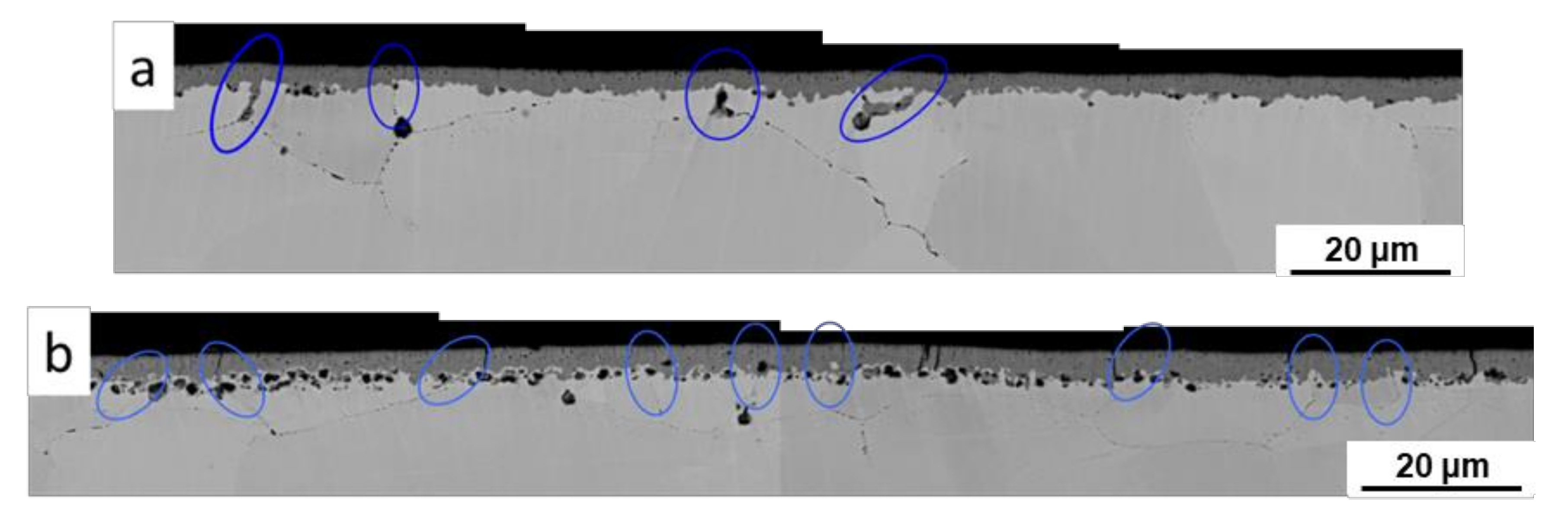
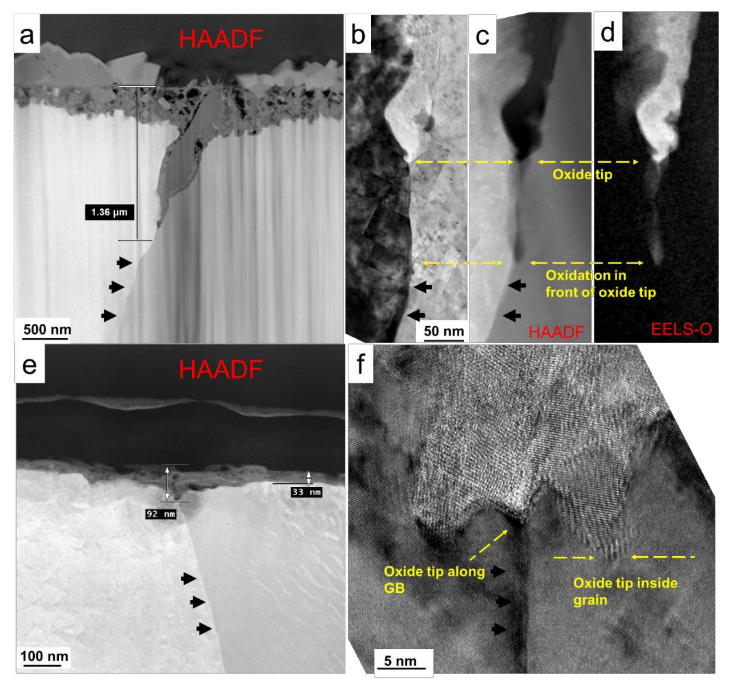
2.2.2. Oxidation Behavior of Alloy 600 with Hydrogen Permeation in High Temperature Water

A water environment provides a more precise simulated condition compared with that in air. The actual environment in nuclear power plant is of a corrosive nature. Water environments introduce the corrosion behavior of the metallic materials, which mechanistically differs from that in air, especially considering that DH is a critical reductant in the electrochemical process.
Figure 4 exhibits quit clear morphologies of alloy 600 oxidized in high temperature water with (a–d) Ar- and (e, f) H-permeation [8]. Figure 4a,e compared the HAADF images of Ar- and H-permeated specimens, respectively. It can be clearly observed that the outer oxide layer of the Ar-permeated specimen was of large size (Figure 4a). This layer was formed via the dissolution of the metallic ions into the water and then deposited back on the surface of the material [9,10]. Beneath the outer oxide layer, an inner oxide layer could be observed, owning to the inward diffusion of the oxygen atom [9,10]. Indeed, the double-layer oxide observed on Ar-permeated specimen in this study did not exhibit a different character compared with that in other studies. This is reasonable given that the gaseous Ar is inert and it was charged from the inner side of the specimen, which should not induce any chemical reaction or the water chemistry change during the oxidation process of the alloy in high temperature water. However, the one with H-permeating shows a completely different character. The oxide film of the Ar-permeated specimen is much thicker than that of H-permeated specimen [7]. Meanwhile, the GB oxidation of the Ar-permeated specimen exhibits a distinguished deeper oxidation than that of H-permeated specimen. Figure 4b–d show the bright field (BF), high angular annual dark field (HAADF), and electron energy loss spectroscopy (EELS)-O images at the tip of the GB, respectively; and Figure 4f exhibits the high resolution (HR)TEM at the tip of the GB with H-permeated specimen. The oxygen diffused much deeper (in front of the oxide tip of the Ar-permeated specimen) than the oxide tip, which also evidences that the GB oxidation largely depends on the inward diffusion of the oxygen along the GB. On the other hand, the H-permeated specimen shows a distinguished suppression on the GB oxidation. The oxidation depth along the GB of H-permeated specimen was only 92 nm, while that of Ar-permeated specimen is about 1.36 µm. When the HRTEM was examined, as shown in Figure 4f, it can be clearly seen that the oxidation at the GB tip was not as fast as that of the adjacent area. This evidence provides a very clear image that the H suppresses the oxidation along the GB.

2.3. Role of Hydrogen in Oxidation Process

The authors would like to emphasize that the water-oxide-metal system consists a complicated system, in which the H influences the oxidation process following multi-mechanisms depending on the different locations that the H diffuses into and the chemical states of the H. A comprehensive illustration of the roles of H in the oxidation process of the metallic materials in high temperature, high pressure water system was given in our previous work [8]. For a better understanding, the authors like to divide the H involved oxidation process as two different categories from different perspectives: the physical and chemical processes. The physical interaction mainly influenced the transport of the ions and the formation of the cavities. Firstly, the concentration of vacancy in the matrix increases due to the existence of H, known as super-abundant-vacancy [14,15,16,17]. The increasing vacancy concentration indicates an acceleration of the atom diffusivity inside the material. H atoms permeated from the matrix can combine as the H2 molecule at the segregation site or voids [18], which may be attributed to the formation of the cavities at the M/O interface, as shown in Figure 3 and other works [19,20,21,22,23,24]. When diffusing into the oxide, H would be ionized as proton [25,26,27], which increases the concentration of the cation vacancy in the oxide film. The outward transport of the cation depends on the inward transport of the cation vacancy in the oxide film [28,29,30]. H increases the ion transport process, therefore, enhances the oxidation rate. Furthermore, it was evidenced that the GB oxidation was highly suppressed by the H permeation (Figure 4), the hypothesis was made such that the H can create a reducing environment when transferring along the GB [8]. All aforementioned behaviors involve only physical processes, in other words, no chemical reaction. On the other hand, H interacting with chemical processes also shows a great influence on the oxidation. H atom can be negatively charged slightly in the matrix. This negatively charged H was believed to facilitate the break of the metallic bonds [31,32,33] and accelerates the oxidation process in its very early stage [6,33,34,35]. Meanwhile, DH was one of the most important factors influencing the corrosion process of the metallic materials, which can change the open circuit potential (OCP) of the materials as many papers suggested. More interestingly, our previous work demonstrated that H permeated from the metal side could also increase the OCP drastically [8]. It is well-known that the OCP affects the electrochemical property and the formation of the surface oxide [6,36,37,38,39], which is critical to the SCC behavior of the material [40,41,42,43,44,45,46]. The sum of each individual mechanism constitutes the multi-mechanism of the interaction between H and the oxidation process in high temperature water.

3. Section 2—The Effects of Neutron Flux/Fluence on Oxidation Kinetics and SCC of 316L and 316LN Stainless Steels—Possible Role of Transmuted H from N

The main objective of this section is to demonstrate the effects of transmutation hydrogen on the corrosion and SCC of 316L and 316LN stainless steels, which were performed as a part of the project of NISA (now NRA) ageing management program [47]. The experimental work had been performed in IFA-727 [48,49] at the HALDEN reactor. The 316LN nuclear grade stainless steel contained more N to improve the solid solution hardening of low carbon 316L. In situ corrosion and SCC tests were performed as a function of exposure time (527.5, 863, 1181 and 2571.5 full power hours, FPH (>2 MW), i.e., 22, 36, 49 and 107 full power days, FPD) in a simulated boiling water reactor (BWR) environment.

3.1. Experimental

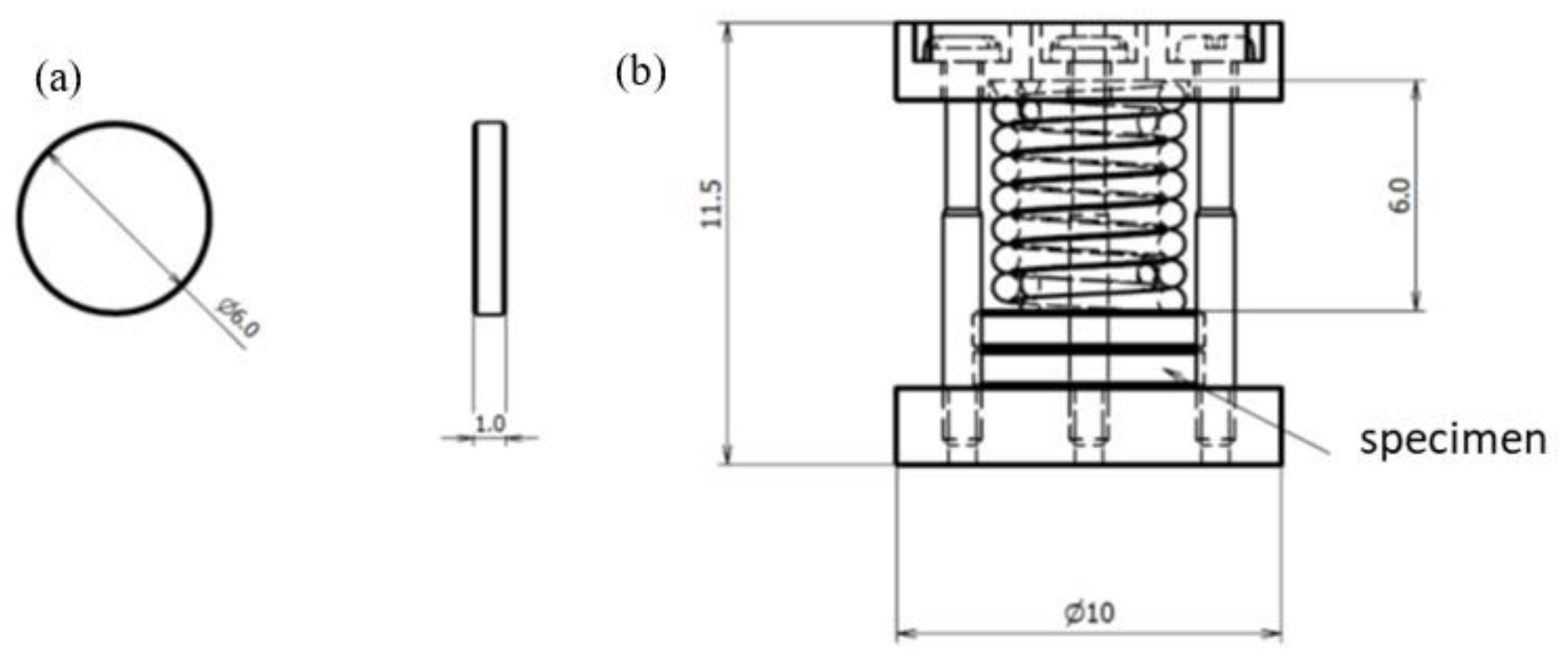
3.1.1. Materials and Test Specimen Geometry

A total of 56 316L SS (# 1) and 316LN SS (# 2) samples were installed in the HALDEN IFA-727 capsule. The chemical composition of 316L SS (# 1) and 316LN SS (# 2) is shown in Table 1.
The specimens, comprising plate samples for the evaluation of general corrosion, compressed crevice samples for evaluation of crevice corrosion, and spring-loaded tensile samples for evaluation of SCC susceptibility, were installed in 4 upper and 4 lower assemblies. The samples located in the 4 upper assemblies were irradiated for 527.5, 863, and 1181 FPH at a high fast neutron flux, while the specimens located in the 4 lower assemblies were irradiated for 2571 FPH at medium and low fast neutron flux conditions. The plate samples have dimensions 10 × 10 × 1 mm3 and their surface is polished with waterproof #4000 polishing paper. The crevice samples with diameter 6 mm and thickness 1 mm were also polished with waterproof #4000 polishing paper and arranged in threes in fixtures where they were compressed with counter dummy disc with an Alloy X-750 spring as shown in Figure 5. The 16 tensile specimens (8 prepared from 316L SS and 8 prepared from 316LN SS), were arranged in pairs in fixtures, were loaded by means an Alloy X-750 spring as shown in Figure 6. As seen from the figure, the tensile samples had 1 mm minor diameter (test section) and 2 mm major diameter gauge regions with R notch of radius of 0.5 mm. The test section of the tensile SCC specimens was prepared as polished with diamond paste and as machined by lathe. The plate samples and tensile and crevice sample fixtures were installed in the upper and lower assemblies with different flux. Prior to installation in IFA-727 and after irradiation, all the samples were weighted on a balance with a resolution of 0.01 mg to evaluate weight gain or loss by oxidation as a function of exposure time with and without irradiation.

3.1.2. Irradiation History and Operating Conditions

Irradiation was carried out in a heavy water moderated and cooled reactor at 240 °C. Nuclear characteristics are thermal neutron flux of 4.5 ± 0.45 × 10⁻⁷ dpa s and fast neutron flux of 3.0 ± 0.3 × 10⁻⁷ dpa s. The variation of neutron flux is about 10% depending upon the location of samples exposed but hereafter, average flux is used to calculate the total damage of samples. The total damage of each sample is calculated based upon the flux rate and exposure time and were 0.026 dpa, 0.039 dpa, 0.060 pda and 0.148 dpa for 22, 36, 49 and 107 FPD exposure, respectively. All samples were exposed in simulated BWR at temperature 285 ± 1 °C measured by coolant thermocouples located in the close proximity to the samples during the irradiation cycle. Water chemistry was controlled as the solution conductivity (average ~0.08 μS/cm) and DO content (average ~2 ppm).

3.2. Results and Discussion

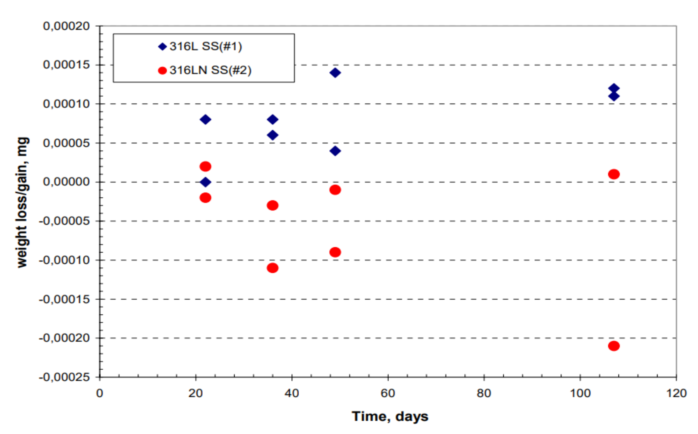
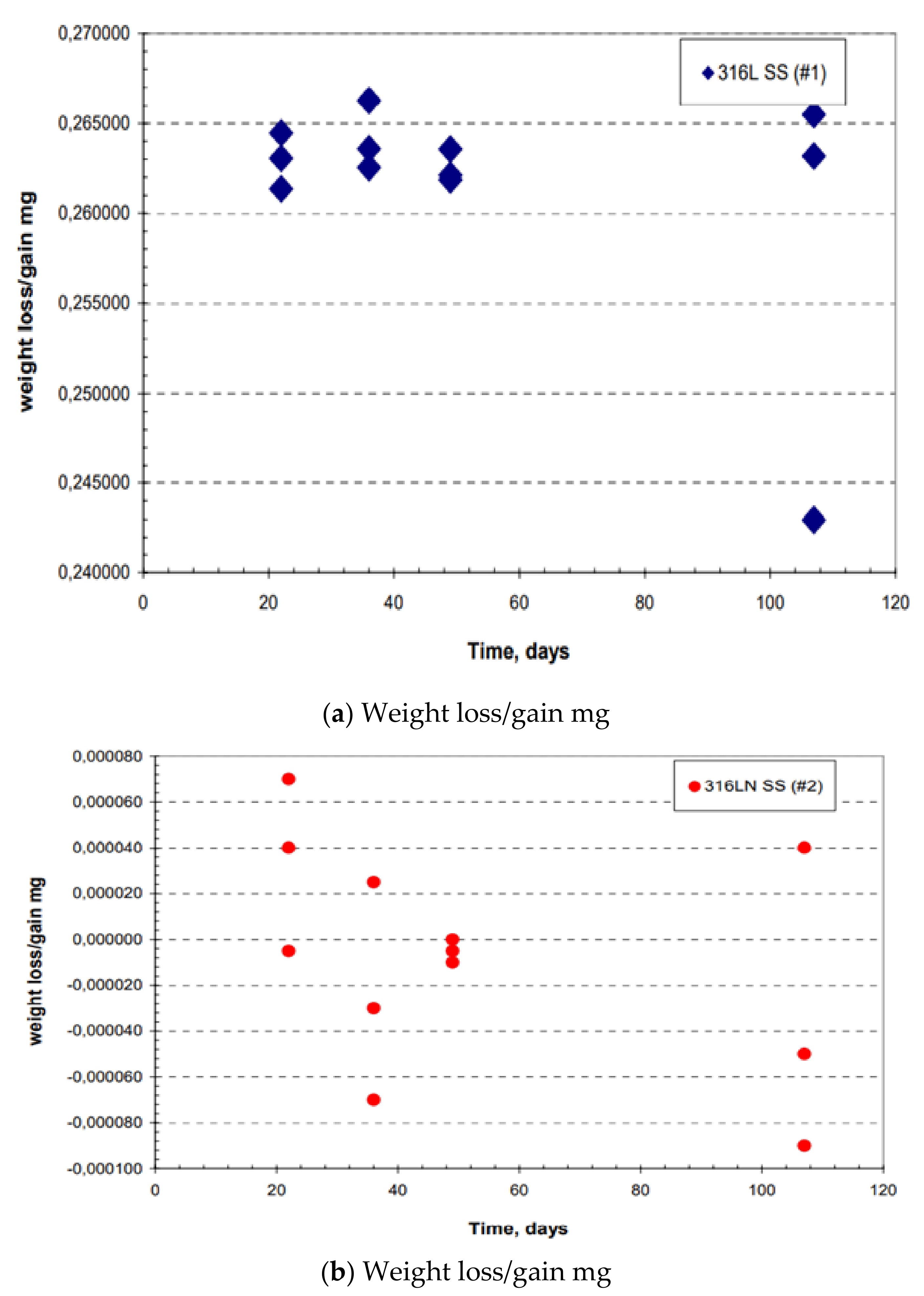
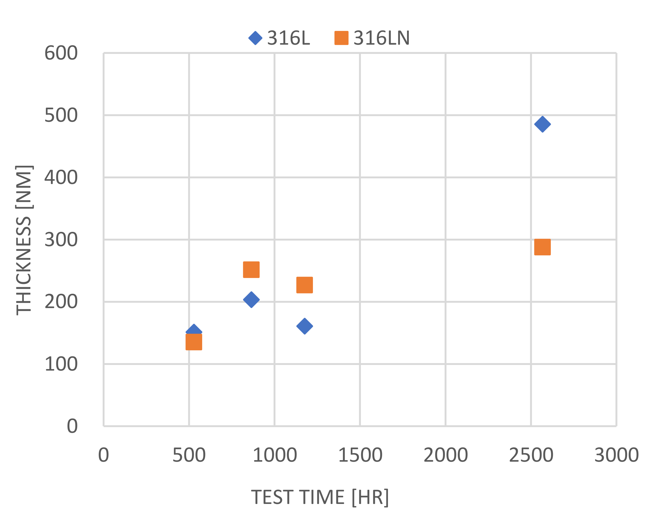
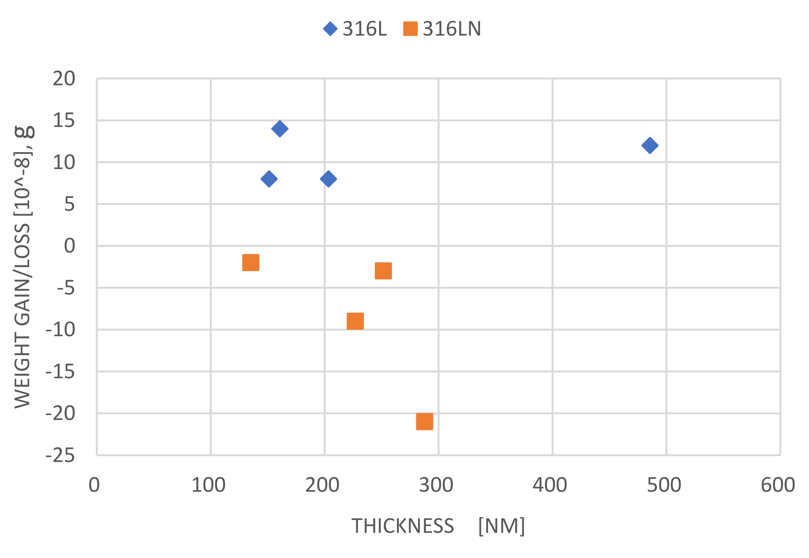
3.2.1. Weight Loss Data of Plate and Creviced Samples

The weighting results for the plate samples are plotted as a function of exposure time in Figure 7. The 316L SS samples exhibited slight weight gain in the range of 0 to 0.00015 mg while 316LN SS samples showed slight weight loss of 0 to −0.0002 mg. The weighting results for the crevice samples are plotted as a function of exposure time in Figure 8a,b. With one exception, 316L SS crevice samples showed larger weight gains (~+0.26 to +0.265) irrespective of exposure time, as shown in Figure 8a. In contrast, with again one exception, 316LN SS crevice samples showed very small, almost negligible (0 to −0.00009 mg) weight losses with increasing exposure time, as shown in Figure 8b. The above results imply that 316LN with higher N content tends to form less protective oxide film than 316L. These results imply the effects of transmuted H on general and crevice corrosion behaviour as follows.
The 316L stainless steel shows a larger weight gain under crevice corrosion than in general corrosion, where a low pH in the crevice degrades the oxide film by hydrogen entry into the metal matrix through the oxide film. Hence, the weight gain is larger in crevice conditions due to the role of hydrogen entry through the oxide film from a low pH crevice environment. Contrarily, 316LN shows a similar corrosion behaviour in general and crevice corrosion, and both show a weight loss, suggesting the oxide film of 316LN is less protective than that of 316L either in general corrosion or in crevice corrosion. Transmuted H in 316LN may play a role to weaken the oxide protective capability similar to H entry into 316L under crevice conditions. Hence, transmuted H plays a key role in corrosion behaviour irrespective of the presence or absence of crevice.

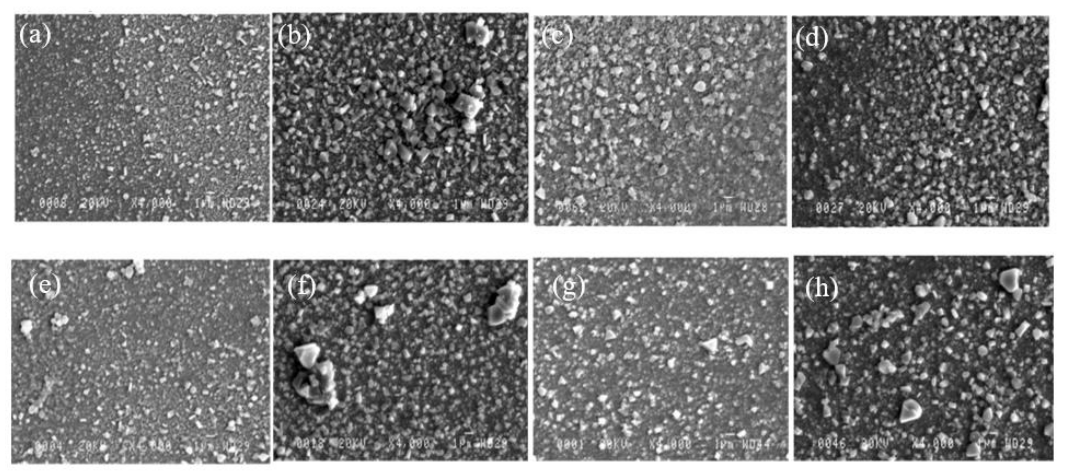
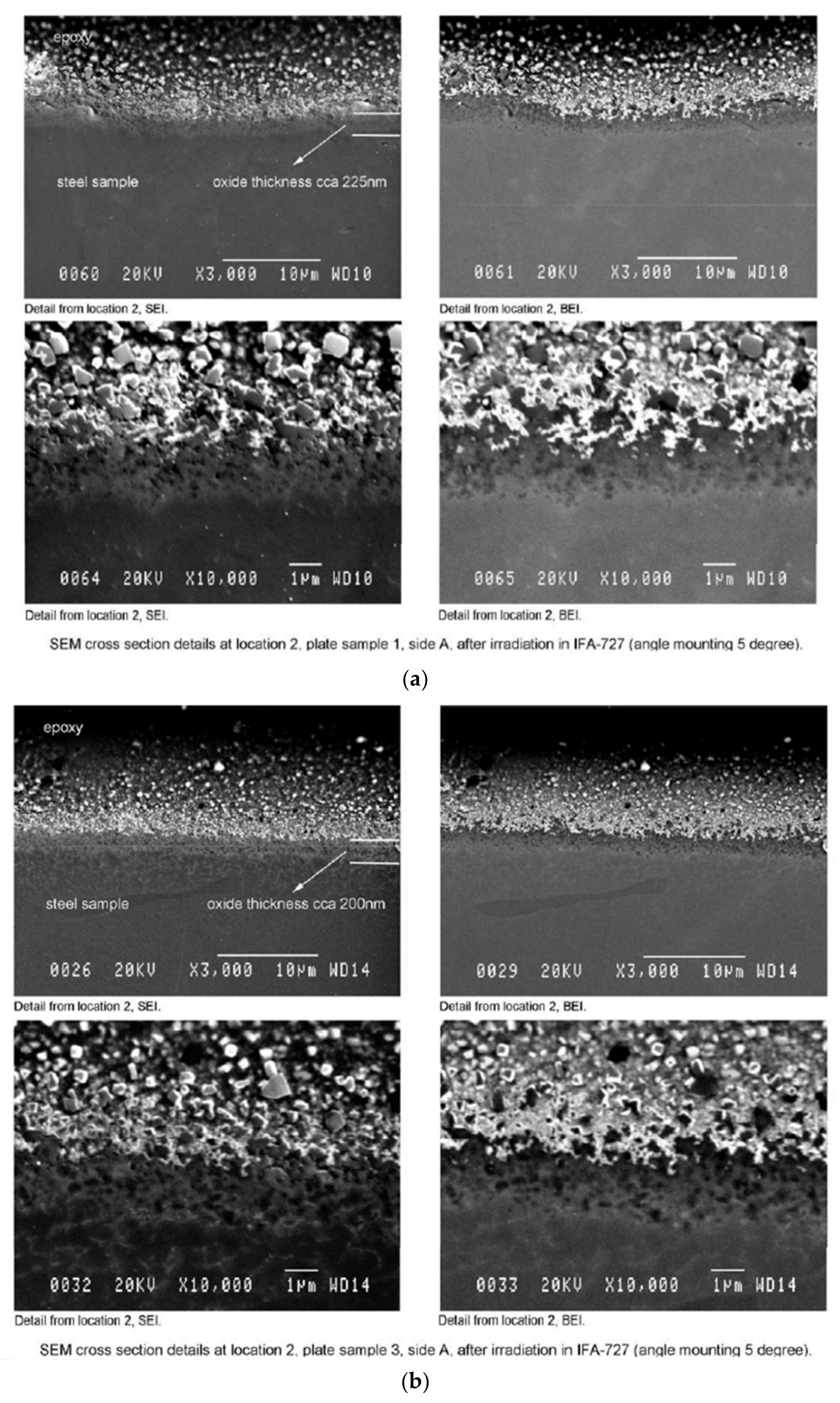
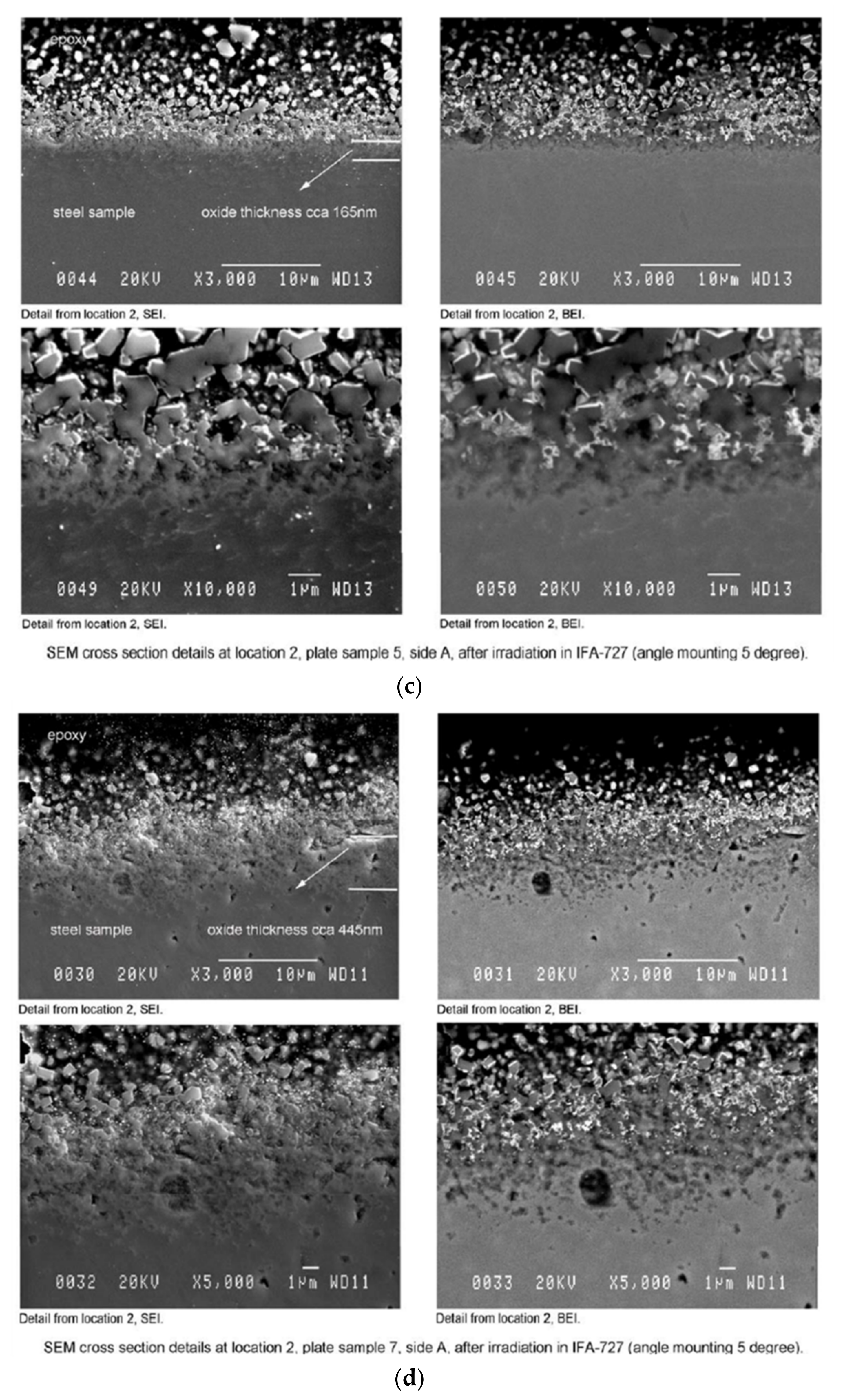
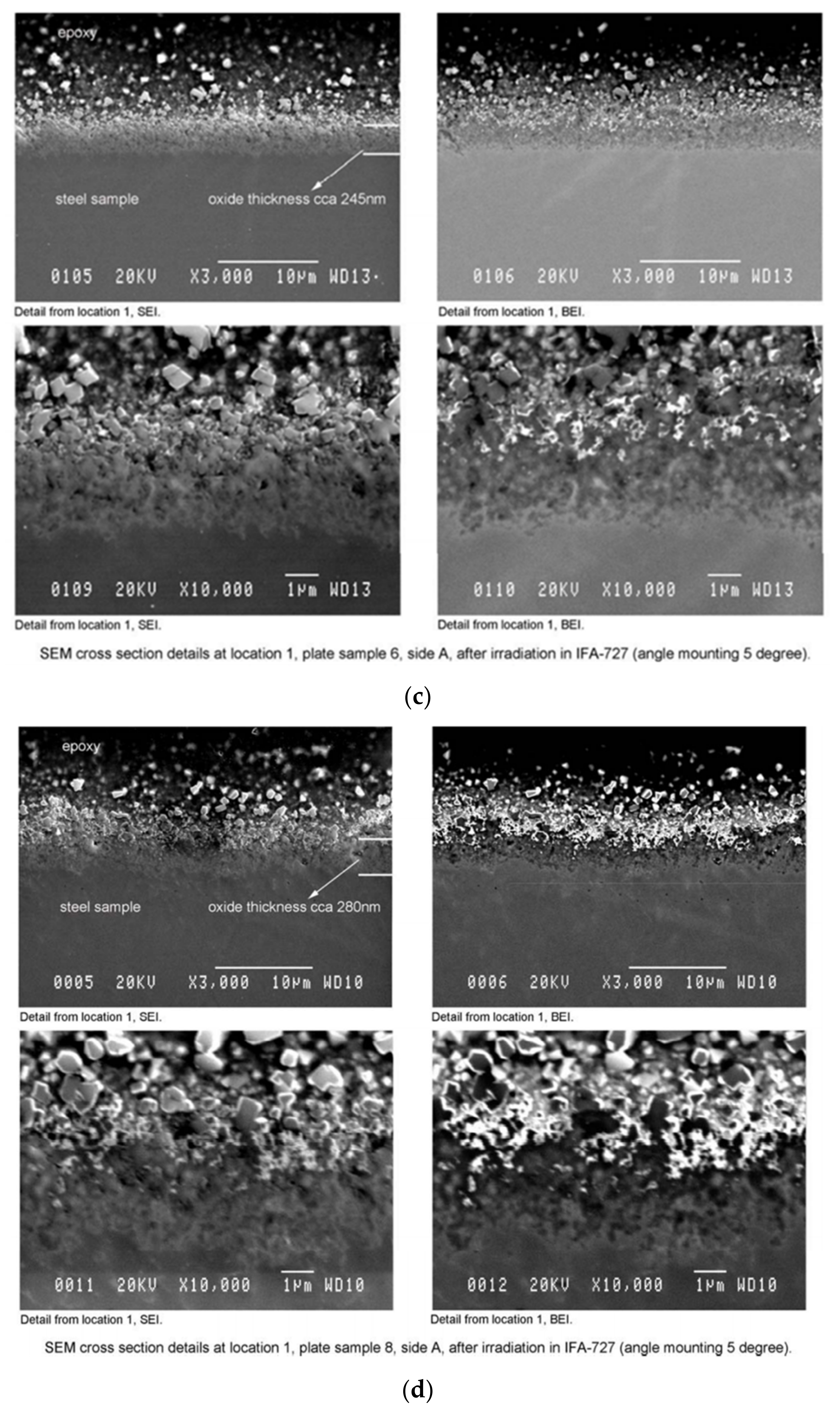
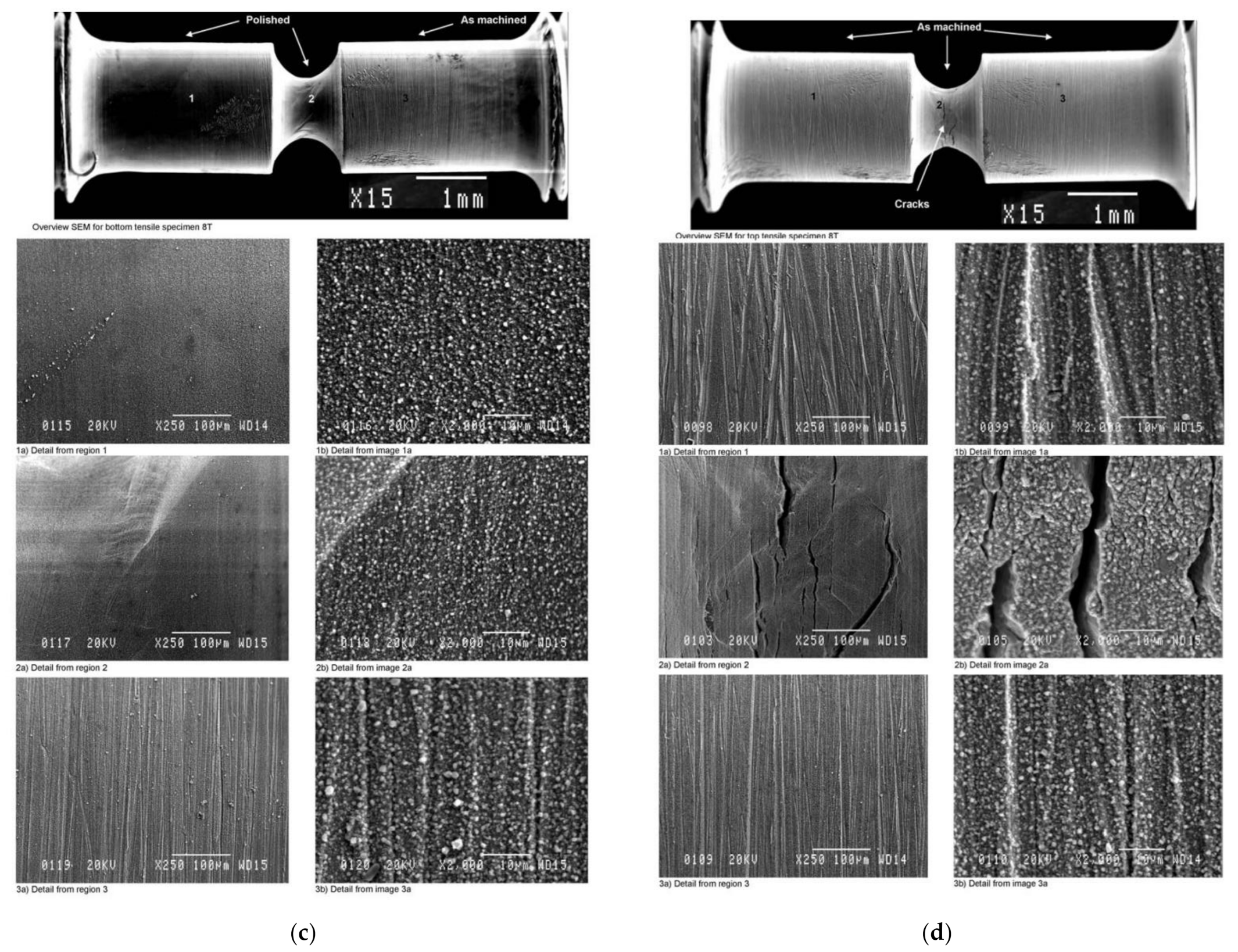
3.2.2. SEM Observation–Surface and Cross-Section

After the exposure to irradiation and high temperature water for the pre-determined time, all surfaces of the samples (plate specimens, notched tensile SCC specimens and creviced specimens) were examined by SEM. Surface oxides particle size and morphology change as a function of FPD are comparatively summarized in Figure 9 for 316L and 316LN SS. Surface oxides on plate samples of 316L SS showed a monotonic tendency that higher does samples showed larger and denser oxides up to 107 FPD. On the contrary, 316LN showed a slightly different behavior where the particle size and density of surface oxides seem to be less at higher does of 49 and 107 FPD and larger deposit oxides are obvious in 316LN SS. This observation agrees well with the data of weight gain/loss of 316L and 316LN SSs where 316L SS showed rather weight gain with testing time but 316LN showed rather weight loss, suggesting surface oxides seems to be less protective than 316L SS. After surface observation by SEM and oxides analysis by Raman spectroscopy, shown later, the plate samples were mounted in epoxy and prepared for SEM examination of sample cross sections of oxides by means of taper or angle mounting at 5° as commonly used to enlarge very thin oxide layers. This angle mounting can enlarge the thin oxides layer about 11.4 times longer in the direction and can analyze the metal/oxide interface in detail. Secondary electron images (SEI) and backscattered electron images (BEI) were taken of samples at different magnifications. The images of the 316L SS samples (taken at two different locations along the cross section) appear in Figure 10a–d. and the images of the 316LN samples appear in Figure 11a–d. From this observation, oxide thickness can be measured. For 316L SS samples, the oxide thickness ranged from 155 to 225 nm for the 22-, 36-, and 49-day exposure samples and 445–465 nm for the 107-day exposure sample. For the 316LN SS samples oxide thicknesses increase with increasing exposure time, with 150 nm oxide thickness on the 22 days exposure sample and 280–375 nm on the 107-day exposure sample as shown in Figure 12. The 316LN SS seems to show rather thinner oxide layer than those of 316L SS. The results of oxide film thickness were plotted in relation to weight gain/loss data of 316L and 316LN SS in Figure 13, which demonstrates particularly that the 316LN oxide film thickness increased while weight decreased. This implies that significant loss of alloying elements took place on 316LN under irradiation condition, which was discussed from an oxidation localization point of view in the reference [50].
Based upon the results outlined above, the observed behavior could be due to hydrogen formed by the transmutation of nitrogen in irradiated steels originating from the following transmutation [51]:
14N + n14C + H
In fact, C 6 14 is known as a tracer for radioactive carbon chronology due to its long half-life period (5730 years). Recently, oxidation acceleration by hydrogen in high temperature water has been reported [6,52]. Hence, one can envisage that a synergistic effect can arise between irradiation damage and hydrogen generation in the steel matrix due to the transformation mentioned above. In order to explain the difference in the oxidation behavior of 316L and 316LN, and to clarify the effect of hydrogen on corrosion, more detailed analysis and study is needed, but it is quite likely that transmuted hydrogen can accelerate an oxidation with water as observed under the condition of hydrogen charged condition in stainless steels and Ni-based alloys. As demonstrated by atomic-scale simulation in [31,32,33,34], hydrogen plays the role of an oxidant in metal by taking a partial electron from metal atoms, such as Fe, Cr, and Ni. Transmuted hydrogen possibly plays a similar role in metal to hydrogen diffused into metal from environments, as demonstrated in atomic-scale simulation.
SEM overview (15×) and higher magnification (250× and 2000×) images, at 3 locations and one orientation, were taken of the polished and as-machined tensile samples. On the as-machined surfaces of the samples, the oxide crystallites appeared more densely deposited than those on the polished surfaces. There also appeared to be a denser deposit of crystallites on the samples having the longer exposure times. No crack was found either in all 316L and in 316LN SS specimens under polished condition. Contrarily, all the specimens of either 316L or 316LN SS were cracked under the lathe machined condition irrespective to exposure FPD. Exposure FPD seems not to be a critical for SCC initiation under as-machined surface condition and crack initiated even at 22 FPD equivalent to 0.026 dpa when the surface is lathe-machined. The typical SEM images for 316L SS with 22 FPD without crack and those for 316LN SS with 107 FPD with crack are shown in Figure 14a–d.
This result can be attributable to the existence of a heavily machined surface layer which introduced a hardened layer at the notch root with dense dislocation and vacancy density. It is well known that 316L and 316LN show a high SCC susceptibility in high temperature waters under such cold-worked conditions and hence, irradiation effects could be covered by this cold work factor and looks no irradiation effects. There are some similarities in microstructure, such as an increase of dislocation density and vacancy formation in both conditions, even though there are some differences in microstructure, such as irradiation cluster formation and transmuted hydrogen formation only in irradiated conditions.

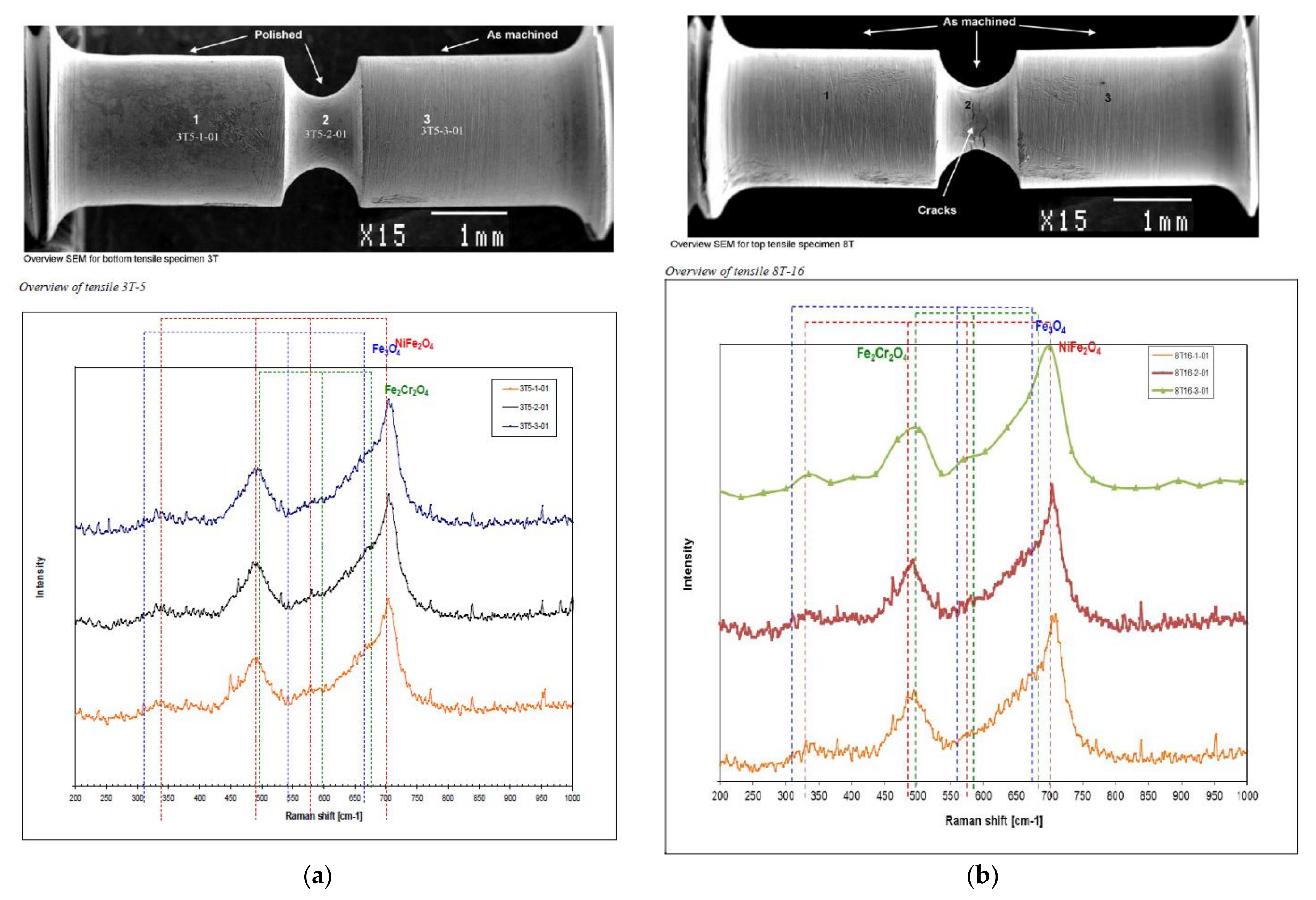
3.2.3. Raman Spectroscopy

Raman spectroscopy was used to characterize the structure of the oxides on some of the plate samples, the crevice samples, and the tensile samples that had been examined in the SEM. The Raman spectra for all samples examined for 316L SS and 316LN SS were identified as NiFe2O4 oxides irrespective to exposure time and there was no clear difference in oxides at outmost layer in plate samples, creviced samples and tensile samples oxidized under stress. Moreover, no difference in outmost layer oxides on the samples as machined by lathe and as mirror polished samples. Typical examples are shown in Figure 15a,b where two Raman spectra obtained on the surfaces oxidized under stress as polished condition exposed for 22 FPD and as machined condition exposed for 107 FPD are compared and shown to be almost the same.
As a result, the 316L SS plate samples exhibited slight weight gain (in the range +0.00005 to ~+0.00015 mg) while the 316LN SS samples showed slight weight loss (~0 to −0.002 mg). SEM observation of surface of samples showed that sparse deposits of fine (<µm) crystallites were evident on the surfaces of the 22-day exposure time samples of 316L and 316LN SS. For the longer exposure times, a denser coverage of crystallites (~1 µm and larger) was apparent on the sample surfaces of 316L SS but not in 316LN. Oxide particle sizes and the distribution of 316LN SS at higher FPD seems not to increase or rather decrease with exposure time. The thickness of the oxides monotonically increased with increasing exposure time, with ~445–465 nm oxide being measured on the 316L SS samples with a 107-day exposure and ~280–375 nm oxide being measured on the 316LN SS samples with a 107-day exposure, slightly thinner than 316L SS. The 316L SS crevice samples showed very similar weight gains (~0.26–0.265 mg) irrespective of exposure time while the 316LN SS crevice samples showed very small (~+0.00004 to +0.00007 mg) weight gain for the shortest exposure time and very small (~0 to −0.00009 mg) weight losses with increasing exposure time.

4. Conclusions

There are many issues that remain to be studied to draw conclusions on how H influences the oxidation process, but we can emphasize the idea that the interaction of H and oxidation does not simply follow a mono-mechanism, but rather an integration of multiple mechanisms, which vary with the different materials, oxidation conditions, the chemical states of H, chemical or physical processes H is involved in, etc. It is difficult to exhaust all possible roles of the H at present. With further in-depth investigation, new synergy mechanisms could be found and new interpretations from different perspectives of the existing data may also emerge. However, attention should be paid to the fact that the multiple mechanisms yield to a competitive law. The apparent oxidation/corrosion phenomenon is a sum of all sub-mechanisms. For instance, DH usually was believed to benefit the materials for lowering the OCP. However, H facilitates the transport of the cations in oxide, accelerating the corrosion process. In this bi-mechanism system, two different mechanisms work contradictorily but exist simultaneously. Therefore, whether the metallic materials are benefited or degraded by the H during its oxidation process depends on which sub-mechanism is dominant. This principle works for multi-mechanisms as well.
The role of hydrogen generated in materials by the transmutation of N in 316LN SS under neutron irradiation seems to be very similar to that by cathodic charging and/or pressurized hydrogen gas. Namely, hydrogen can play the role of an oxidant in metal and at the metal/oxide interface to pre-oxidize metal elements, such as Cr, Ni, and Fe, and promote inward oxygen diffusion and the oxidation rate at the interface. Moreover, hydrogen may play the role of reductant in oxides where existing oxides can be reduced. Then, the protective capability of oxides will be decreased to result in oxidation acceleration at metal/oxide interface. These phenomena were observed in Ni-based alloy and possibly austenitic stainless steel containing N such as 316LN SS.
The influence of neutron irradiation on corrosion and SCC behavior in a simulated BWR water environment were examined. The effects of transmuted H on general and crevice corrosion behavior were examined by the use of 316L and 316LN stainless steels with different N contents, where more transmuted H is generated in 316LN with higher N than 316L. The effects of neutron irradiation on SCC initiation were also examined on 316L SS with different surface finish conditions, where the surface of R notch root of specimens was prepared in mirror polish condition by diamond paste polish and as machined by lathe.
For the tensile specimens, the oxide crystallites appeared more densely deposited on the as-machined than on the polished surfaces, with denser deposits of crystallites on the samples having the longer exposure times. Cracks were also evident in the higher stress, 1 mm diameter gauge regions of the as-machined specimens. For the crevice samples, evidence of a crevice environment was found in several cases, where SEM images showed very smooth surfaces. The oxides on the plate, tensile, and crevice samples were identified as NiFe2O4.
This work demonstrates a part of the role of hydrogen on oxidation, and more extensive and systematic work is needed to delineate the role of hydrogen on oxidation with and without irradiation.

Author Contributions

Conceptualization, Z.W. and T.S.; methodology, Z.W. and T.S.; validation, Z.W. and T.S.; formal analysis, Z.W. and T.S.; investigation, Z.W. and T.S.; resources, T.S.; data curation, Z.W. and T.S.; writing—original draft preparation, Z.W. and T.S.; writing—review and editing, Z.W. and T.S.; project administration, T.S.; funding acquisition, T.S. All authors have read and agreed to the published version of the manuscript.

Funding

A part of this work was supported by the Nuclear and Industry Safety Agency, NISA (now Nuclear Regulatory Authority, NRA), Ageing Management Program (2006–2010) and Irradiation tests were performed at HALDEN reactor as IFA-727.

Data Availability Statement

The data presented in this study are available on request from the corresponding author. The data are not publicly available due to regulation by funding agency.

Acknowledgments

A part of this work was supported by the NISA (now NRA) Ageing Management Program and Irradiation tests were performed at HALDEN reactor as IFA-727. The authors would like to express their thanks to those who are involved in this program as Tohoku-Hokkaido Cluster activities. Special thanks extend to Yo-ichi Takeda of Tohoku University for his valuable support in preparation of testing at HALDEN reactor.

Conflicts of Interest

The authors declare no conflict of interest.

References and Notes

  1. Takiguchi, H.; Ullberg, M.; Uchida, S. Optimization of dissolved hydrogen concentration for control of primary coolant radiolysis in pressurized water reactors. J. Nucl. Sci. Technol. 2004, 41, 601–609. [Google Scholar] [CrossRef]
  2. Economy, G.; Jacko, R.J.; Begley, J.A.; Pement, F.W. Influence of Hydrogen Partial Pressure on the IGSCC Behavior of Alloy 600 Tubing in 360/Sup 0/C Water or 400/Sup 0/C Steam; National Association of Corrosion Engineers: Houston, TX, USA, 1987. [Google Scholar]
  3. Domian, H.A.; Emanuelson, R.H.; Sarver, L.W.; Theus, G.J.; Katz, L. Effect of microstructure on stress corrosion cracking of Alloy 600 in high purity water. Corrosion 1977, 33, 26–38. [Google Scholar] [CrossRef]
  4. Jambon, F.; Marchetti, L.; Jomard, F.; Chêne, J. Mechanism of hydrogen absorption during the exposure of alloy 600-like single-crystals to PWR primary simulated media. J. Nucl. Mater. 2011, 414, 386–392. [Google Scholar] [CrossRef]
  5. Xiong, Y.; Watanabe, Y.; Shibayama, Y. Effects of dissolved hydrogen on low-cycle fatigue behaviors and hydrogen uptake of 316LN austenitic stainless steel in simulated pressurized water reactor primary water. Int. J. Fatigue 2020, 134, 105457. [Google Scholar] [CrossRef]
  6. Hou, J.; Peng, Q.J.; Sakaguchi, K.; Takeda, Y.; Kuniya, J.; Shoji, T. Effect of hydrogen in Inconel Alloy 600 on corrosion in high temperature oxygenated water. Corros. Sci. 2010, 52, 1098–1101. [Google Scholar] [CrossRef]
  7. Wang, Z.; Taleda, Y. Mechanistic Understanding of the Role of Hydrogen in Modification of Oxide Film of Alloy 600 in High Temperature High Pressure Water Environment. Corros. Sci. 2020, 170, 108656. [Google Scholar] [CrossRef]
  8. Wang, Z.; Takeda, Y. Roles of permeated hydrogen in the oxidation process of Ni-based alloy in high temperature water environment. Corros. Sci. 2021, 179, 109139. [Google Scholar] [CrossRef]
  9. Ziemniak, S.E.; Hanson, M. Corrosion behavior of NiCrFe Alloy 600 in high temperature, hydrogenated water. Corros. Sci. 2006, 48, 498–521. [Google Scholar] [CrossRef] [Green Version]
  10. Kuang, W.; Wu, X.; Han, E.H.; Rao, J. The mechanism of oxide film formation on Alloy 690 in oxygenated high temperature water. Corros. Sci. 2011, 53, 3853–3860. [Google Scholar] [CrossRef]
  11. Fournier, L.; Calonne, O.; Combrade, P.; Scott, P.; Chou, P.; Pathania, R. Grain boundary oxidation and embrittlement prior to crack initiation in Alloy 600 in PWR primary water. In Proceedings of the 15th International Conference on Environmental Degradation of Materials in Nuclear Power Systems—Water Reactors; Springer: Cham, Switzerland, 2011; pp. 1491–1501. [Google Scholar]
  12. Kuang, W.; Song, M.; Was, G.S. Insights into the stress corrosion cracking of solution annealed alloy 690 in simulated pressurized water reactor primary water under dynamic straining. Acta Mater. 2018, 151, 321–333. [Google Scholar] [CrossRef]
  13. Tveten, B.; Hultquist, G.; Norby, T. Hydrogen in chromium: Influence on the high-temperature oxidation kinetics in O2, oxide-growth mechanisms, and scale adherence. Oxid. Met. 1999, 51, 221–233. [Google Scholar] [CrossRef]
  14. Fukai, Y.; Akuma, N. Formation of superabundant vacancies in Pd hydride under high hydrogen pressures. Phys. Rev. Lett. 1994, 73, 1640–1643. [Google Scholar] [CrossRef]
  15. Fukai, Y. Superabundant Vacancies Formed in Metal Hydrogen Alloys. Phys. Scr. 2003, 103, 11–14. [Google Scholar] [CrossRef]
  16. Fukai, Y.F.Y.; Ōkuma, N.Ō.N. Evidence of copious vacancy formation in Ni and Pd under a high hydrogen pressure. Jpn. J. Appl. Phys. 1993, 32, L1256–L1259. [Google Scholar] [CrossRef]
  17. Fukai, Y.; Ishii, Y.; Goto, Y.; Watanabe, K. Formation of superabundant vacancies in Pd-H alloys. J. Alloys Compd. 2000, 313, 121–132. [Google Scholar] [CrossRef]
  18. Li, M.; Xie, D.G.; Ma, E.; Li, J.; Zhang, X.X.; Shan, Z.W. Effect of hydrogen on the integrity of aluminium-oxide interface at elevated temperatures. Nat. Commun. 2017, 8, 14564. [Google Scholar] [CrossRef] [Green Version]
  19. Wang, Z.; Takeda, Y. Hydrogen Assisted Oxidation Behavior of Alloy 600 in High Temperature Air Environment by in-situ H Charging Method. In Proceedings of the 19th International Conference on Environmental Degradation of Materials in Nuclear Power Systems—Water Reactors, Boston, MA, USA, 18–22 August 2019; American Nuclear Society: La Grange Park, IL, USA, 2019; pp. 1304–1310. [Google Scholar]
  20. Wang, Z.; Takeda, Y. Elemental Distribution in Oxide Film Formed by Hydrogen Penetration Using Dual-Exposed Specimen; IICAPP: Dublin, Ireland, 2019. [Google Scholar]
  21. Yang, Z.; Walker, M.S.; Singh, P.; Stevenson, J.W.; Norby, T. Oxidation Behavior of Ferritic Stainless Steels under SOFC Interconnect Exposure Conditions. J. Electrochem. Soc. 2004, 151, B669–B678. [Google Scholar] [CrossRef]
  22. Yang, Z.; Walker, M.S.; Singh, P.; Stevenson, J.W. Anomalous Corrosion Behavior of Stainless Steels under SOFC Interconnect Exposure Conditions, Electrochem. Solid-State Lett. 2003, 6, B35–B37. [Google Scholar] [CrossRef]
  23. Yang, Z.; Xia, G.; Singh, P.; Stevenson, J.W. Effects of water vapor on oxidation behavior of ferritic stainless steels under solid oxide fuel cell interconnect exposure conditions. Solid State Ion. 2005, 176, 1495–1503. [Google Scholar] [CrossRef]
  24. Yang, Z.; Xia, G.G.; Walker, M.S.; Wang, C.M.; Stevenson, J.W.; Singh, P. High temperature oxidation/corrosion behavior of metals and alloys under a hydrogen gradient. Int. J. Hydrogen Energy 2007, 32, 3770–3777. [Google Scholar] [CrossRef]
  25. Pankove, J.I.; Johnson, N.M. Hydrogen in Semiconductors; Academic Press: Boston, MA, USA, 1991. [Google Scholar]
  26. Norby, T. The influence of hydrogen defects on transport properties of oxides. Am. Ceram. Soc. Inc. Nonstoichiom. Compd. Adv. Ceram. 1987, 23, 107–123. [Google Scholar]
  27. Norby, T. Protonic defects in oxide and their possible role in high temperature oxidation. J. Phys. IV 1993, 3, 99–106. [Google Scholar] [CrossRef]
  28. Wallinder, D.; Hultquist, G.; Tveten, B.; Hörnlund, E. Hydrogen in chromium: Influence on corrosion potential and anodic dissolution in neutral NaCl solution. Corros. Sci. 2001, 43, 1267–1281. [Google Scholar] [CrossRef]
  29. Wallinder, D.; Hörnlund, E.; Hultquist, G. Influence of Hydrogen in Iron and in Two Stainless Steels on Aqueous and Gaseous Corrosion. J. Electrochem. Soc. 2002, 149, B393. [Google Scholar] [CrossRef]
  30. Hultquist, G.; Tveten, B.; Norby, T. Hydrogen in chromium: Influence on the high-temperature oxidation kinetics in H2O, oxide-growth mechanisms, and scale adherence. Oxid. Met. 1999, 54, 1–10. [Google Scholar] [CrossRef]
  31. Das, N.K.; Suzuki, K.; Ogawa, K.; Shoji, T. Early stage SCC initiation analysis of fcc Fe-Cr-Ni ternary alloy at 288 °C: A quantum chemical molecular dynamics approach. Corros. Sci. 2009, 51, 908–913. [Google Scholar] [CrossRef]
  32. Das, N.K.; Suzuki, K.; Takeda, Y.; Ogawa, K.; Shoji, T. Quantum chemical molecular dynamics study of stress corrosion cracking behavior for fcc Fe and Fe-Cr surfaces. Corros. Sci. 2008, 50, 1701–1706. [Google Scholar] [CrossRef]
  33. Das, N.K.; Shoji, T. An atomic study of hydrogen effect on the early stage oxidation of transition metal surfaces. Int. J. Hydrogen Energy 2013, 38, 1644–1656. [Google Scholar] [CrossRef]
  34. Das, N.K.; Shoji, T. Early stage oxidation of Ni-Cr binary alloy 111, 110 and 100 surfaces: A combined density functional and quantum chemical molecular dynamics study. Corros. Sci. 2013, 73, 18–31. [Google Scholar] [CrossRef]
  35. Xu, J.; Shoji, T. The corrosion behavior of Alloy 182 in a cyclic hydrogenated and oxygenated water chemistry in high temperature aqueous environment. Corros. Sci. 2016, 104, 248–259. [Google Scholar] [CrossRef]
  36. Zhang, Z.; Wang, J.; Han, E.H.; Ke, W. Analysis of surface oxide film formed on eletropolished alloy 690tt in high temperature and high pressure water with sequentially dissolved hydrogen and oxygen. Jinshu Xuebao/Acta Metall. Sin. 2015, 51, 85–92. [Google Scholar] [CrossRef]
  37. Mendonça, R.; Bosch, R.W.; van Renterghem, W.; Vankeerberghen, M.; Figueiredo, C.d. Effect of temperature and dissolved hydrogen on oxide films formed on Ni and Alloy 182 in simulated PWR water. J. Nucl. Mater. 2016, 477, 280–291. [Google Scholar] [CrossRef]
  38. Attanasio, S.A.; Morton, D.S.; Ando, M.A.; Panayotou, N.F.; Thompson, C.D. Measurement of the Nickel/Nickel Oxide Phase Transition in High Temperature Hydrogenated Water Using the Contact Electric Resistance CER Technique; Lockheed Martin Corporation: Schenectady, NY, USA, 2001. [Google Scholar]
  39. Terachi, T.; Totsuka, N.; Yamada, T.; Nakagawa, T.; Deguchi, H.; Horiuchi, M.; Oshitani, M. Influence of dissolved hydrogen on structure of oxide film on alloy 600 formed in primary water of pressurized water reactors. J. Nucl. Sci. Technol. 2003, 40, 509–516. [Google Scholar] [CrossRef]
  40. Andresen, P.L.; Hickling, J.; Ahluwalia, A.; Wilson, J. Effects of hydrogen on stress corrosion crack growth rate of nickel alloys in high-temperature water. Corrosion 2008, 64, 707–720. [Google Scholar] [CrossRef]
  41. Totsuka, N.; Kamaya, M.; Nakajima, N.; Mitsuda, H. SS, A New Evaluation Method for Short Crack Growth and Influence of Dissolved Hydrogen on PWSCC of Alloy 600 the Principles of Crack Growth Rate Evaluation Method. In Proceedings of the 10th International Conference on Environmental Degradation of Materials in Nuclear Power Systems—Water Reactors, Lake Tahoe, NE, USA, 5–9 August 2001. [Google Scholar]
  42. Guerre, C.; Laghoutaris, P.; Chêne, J.; Marchetti, L.; Molins, R.; Duhamel, C.; Sennour, M. Stress Corrosion Cracking of Alloy 600 in PWR Primary Water: Influence of Chromium, Hydrogen and oxygen Diffusion. In Proceedings of the 15th International Conference on Environmental Degradation of Materials in Nuclear Power Systems—Water Reactors; Springer: Cham, Switzerland, 2017. [Google Scholar] [CrossRef]
  43. Morton, D.; Fish, J.; Schurman, M.K.; Attanasio, S.A. Influence of Dissolved Hydrogen on Nickel Alloy SCC in High Temperature Water. In CORROSION 99; OnePetro: Richardson, TX, USA, 1999. [Google Scholar]
  44. Andresen, P.L.; Morra, M.M. IGSCC of non-sensitized stainless steels in high temperature water. J. Nucl. Mater. 2008, 383, 97–111. [Google Scholar] [CrossRef]
  45. Nakagawa, T.; Totsuka, N.; Terachi, T.; Nakajima, N. Influence of Dissolved Hydrogen on Oxide Film and PWSCC of Alloy 600 in PWR Primary Water. J. Nucl. Sci. Technol. 2003, 40, 39–43. [Google Scholar] [CrossRef]
  46. Andresen, P.L.; Chou, P. Effects of Hydrogen on SCC Growth Rate of NI Alloys in BWR Water. In Proceedings of the 15th International Conference on Environmental Degradation of Materials in Nuclear Power Systems—Water Reactors; Springer: Cham, Switzerland, 2017. [Google Scholar] [CrossRef]
  47. Mitsubishi Research Institute Inc. (Ed.) NISA Project on Enhancement of Ageing Management and Maintenance of Nuclear Power Stations 2006.4–2011.3. In Proceedings of the Inetrnational Symposium on the Ageing Management & Maintenance of Nuclear Power Plants, ISaG2020, Tokyo, Japan, 27–28 May 2010. [Google Scholar]
  48. Kim, J.-C. Calculation of relative axial gamma flux profile for IFA-727, CP-Note 10-01. 5 January 2010. [Google Scholar]
  49. Kim, J.-C. Fluence determination for IFA-727.1 using flux monitor wire results, CP-Note 09-40. 30 November 2009. [Google Scholar]
  50. Takeda, Y.; Sato, T.; Yamauchi, D.; Shoji, T.; Ohji, A. Non-lnear dynamics of the morphology at the oxide/metal interface of austenitic steels in simulated light water reactor environmenets and its implications for SCC initiation. In Proceedings of the 15th International Conference on Environmental Degradation of Materials in Nuclear Power Systems—Water Reactors; Springer: Cham, Switzerland, 2011; pp. 409–419. [Google Scholar]
  51. Harasawa, S. Radioisotope; Corona Publishing Co., Ltd.: Tokyo, Japan, 1979. (In Japanese) [Google Scholar]
  52. Das, N.K.; Suzuki, K.; Taakeda, Y.; Ogawa, K.; Shoji, T. Stress Corrosion Cracking Analysis of Fe 111 and Fe-Cr 111 Surfaces at Different Temperatures by Quantum Chemical Molecular Dynamics. In Proceedings of the 16th Pacific Basin Nuclear Conference, Aomori, Japan, 1 July 2008. [Google Scholar]
Figure 1. Magnified cross-sectional morphologies of (a) Ar- and (b) H-charged metallic Ni specimen.
Cmd 03 00017 g001
Figure 2. SEM morphologies of (a) Ar- and (b) H-permeated specimen; (c) Ni and (d) O distribution of H-permeated specimen obtained by AES.
Cmd 03 00017 g002
Figure 3. SEM morphologies of internal oxidation along grain boundaries of (a) Ar- and (b) H-permeated specimens.
Cmd 03 00017 g003
Figure 4. (a) HAADF image at the GB of the Ar-exposed specimen; and the related (bd) magnified TEM-BF, HAADF, and O intensity images of the oxide tip of the GB; (e) HAADF image at GB for the H-exposed specimen, and the related (f) magnified TEM-BF image of the oxide tip of the GB [8].
Cmd 03 00017 g004
Figure 5. Crevice specimen geometry and dimension and contact pressure control jigs.
Cmd 03 00017 g005
Figure 6. Loading jigs for SCC tests on round notched tensile specimen: (a) loading jigs laboratory tests and geometry and dimension of notched tensile specimen and (b) loading jigs for test under irradiation.
Cmd 03 00017 g006
Figure 7. Weight gain/loss of plate specimens of 316L and 316LN exposed in simulated BWR environments under irradiation as a function of exposure time, FPD.
Cmd 03 00017 g007
Figure 8. Weight gain/loss of creviced samples as a function of exposure time in simulated BWR environments under irradiation of 316L (a) and 316LN SS (b).
Cmd 03 00017 g008
Figure 9. SEM details of 316L (ad) and 316LN (eh) SS plate samples with different FPD exposure.
Cmd 03 00017 g009
Figure 10. (a) Backscattered and secondary electron images from location 2 of 316L SS plate specimen 3, side A with a 22-day exposure time. (b) Backscattered and secondary electron images from location 2 of 316L SS plate specimen 1, side A with a 36-day exposure time. (c) Backscattered and secondary electron images from location 2 of 316L SS plate specimen 5, side A with a 49-day exposure time. (d) Backscattered and secondary electron images from location 2 of 316L SS plate specimen 7, side A with a 107-day exposure time.
Cmd 03 00017 g010aCmd 03 00017 g010b
Figure 11. (a) Backscattered and secondary electron images from location 2 of 316LN SS plate specimen-4, side A with a 22-day exposure time. (b) Backscattered and secondary electron images from location 1 of 316LN SS plate specimen 2, side A with a 36-day exposure time. (c) Backscattered and secondary electron images from location 2 of 316LN SS plate specimen-4, side A with a 22-day exposure time. (d) Backscattered and secondary electron images from location 1 of 316LN SS plate specimen 8, side A with a 107-day exposure time.
Cmd 03 00017 g011aCmd 03 00017 g011b
Figure 12. Relation between oxide film total thickness and testing time obtained under irradiation condition by using a plate type specimen.
Cmd 03 00017 g012
Figure 13. Relation between oxide film thickness and oxidation weight gain/loss obtained under irradiation condition by using a plate type specimen.
Cmd 03 00017 g013
Figure 14. (a) SEM overview and details at locations 1, 2 and 3 for 316L SS tensile specimen 3T-5 (with polished regions) with 22 full power day exposure; (b) SEM overview and details at locations 1, 2 and 3 for 316L SS tensile specimen 3T-6 (as-machined) with 22 full power day exposure; (c) SEM overview and details at locations 1, 2 and 3 for 316LN SS tensile specimen 8T-15 (with polished regions) with 107 full power day exposure; (d) SEM overview and details at locations 1, 2 and 3 for 316LN SS tensile specimen 8T-16 (as-machined) with 107 full power day exposure.
Cmd 03 00017 g014aCmd 03 00017 g014b
Figure 15. (a) Raman spectra of IFA-727.2, tensile sample 3T-5 (316L SS with polished regions), after 22 full power day irradiation in the HBWR; (b) Raman spectra of IFA-727.2, tensile sample 8T-14 (as-machined 316LN SS), after 107 full power day irradiation in the HBWR.
Cmd 03 00017 g015
Table 1. Chemical composition of 316L and 316LN.
AlloyCSiMnPSNiCrMoFeN
316 #10.0180.470.820.0280.00112.0617.682.17Bal.0.039
316 #2
(Nucl. grade)
0.0200.500.810.0250.00212.8916.592.39Bal.0.094
Publisher’s Note: MDPI stays neutral with regard to jurisdictional claims in published maps and institutional affiliations.

