Article

Localized Corrosion of Mooring Chain Steel in Seawater

1
Endures BV, Bevesierweg 1 DC002, 1781 CA Den Helder, The Netherlands
2
TNO, Leeghwaterstraat 44, 2628 CA Delft, The Netherlands
*
Author to whom correspondence should be addressed.
Corros. Mater. Degrad. 2022, 3(1), 53-74; https://doi.org/10.3390/cmd3010004
Submission received: 12 October 2021 / Revised: 31 January 2022 / Accepted: 8 February 2022 / Published: 16 February 2022

Abstract

:
Corrosion of mooring chains is regarded as one of main threats to the offshore mooring systems. Localized corrosion is even more dangerous than uniform corrosion because it may not show significant mass loss but it can cause stress concentration and initiate cracks under force, leading to accelerated degradation of mooring chains. Localized corrosion of steel in seawater is influenced by many factors such as the local heterogeneities of the steel, and the local electrochemical and microbiological environments. It is difficult to predict and the mechanism is not fully understood. The aim of this work was to study the mechanism of localized corrosion on mooring chain steel in seawater which is helpful in the search for corresponding monitoring tools and mitigation methods. The corrosion behavior of chain steel grade R4 was studied in artificial seawater and artificial seawater containing microorganisms collected from a practice field. The corrosion behavior of the steel was studied using different techniques such as potentiodynamic polarization, linear polarization resistance measurements and electrochemical impedance spectroscopy. The microstructures such as inclusions and compositions of the chain steel were studied using SEM: Scanning Electron Microscope and EDS: Energy Dispersive Spectroscopy. The microbial cells were observed using epi-fluorescence microscopy. The corrosion morphology and pit geometry were investigated using photo-microscopy. The localized corrosion rate has been found to be much higher than the uniform corrosion rate of the steel in the seawater in the presence of bacteria. In the case of localized corrosion, applying uniform corrosion measurement techniques and formulas is not considered representative. The representative areas have to be introduced to match physical results with the measurements. Inclusions, such as MnS and TiVCr found in the steel have a critical influence on localized corrosion. The corrosion mechanism of the steel in seawater is discussed.

1. Introduction

Mooring chains are widely used to fix a floating production, storage and offloading (FPSO) system. Mooring chain steel has to withstand seawater corrosion and cyclic force loading during service. Marine corrosion, in particular localized corrosion, combined with mechanical loading is the main reason for mooring chain failures [1,2,3,4]. Ma et al. compiled a historical review of integrity issues of mooring systems [1]. They found that the chain, connector and wire rope are the top three components causing more incidents. Fontaine et al. undertook an industry survey of past failures and degradations for mooring systems of floating production units. They found that almost half of all failures were associated with chains and two out of three chain failures were related to corrosion and fatigue [2].
Many factors affect the corrosion of metals in marine environments. Marine environments include a number of zones, such as atmospheric, splash, tidal, submerged and bottom sediment areas. Some recovered chain links showed uniform corrosion in the splash zone and pitting corrosion in the submerged near-surface zone [5]. Microbial activity in concentrations around and below the low water zone leads to an aggressive form of concentrated corrosion, known as accelerated low water corrosion, which has been identified as microbiologically influenced corrosion (MIC) [6,7].
The steels for making mooring chains are classified so far by specified minimum ultimate tensile strength into five grades (R3, R3s, R4, R4s and R5) [8]. To achieve the required strength the chemical compositions and manufacture processes have to comply with the approved specifications [8,9]. Even so, the steels showed different corrosion rates in different seawater areas. It was reported that 120 mm diameter R4 chain serviced in the North Sea located in the Pierce field for 13 years has a corrosion rate of 0.53 mm/y of diameter reduction in the pitted area (for the worst case) [10]. Fontaine al. inspected 76 mm-diameter chain links of type R3 and ORQ grades in West African waters [11]. The long-term corrosion rate of these links was approximately 1.5 mm/y of dimeter reduction in the pitted areas, which is significantly higher than the corrosion wear allowance of 1 mm/y required for tropic waters [12,13].
Local corrosion attack may initiate at inclusions or grain boundaries due to a local electrochemical potential difference [14,15,16]. Avci et al. investigated MnS-mediated pit initiation and propagation in carbon steel in an anaerobic sulfidogenic media. They found that pitting on 1018 carbon steel was initiated within a 20–30 nm zone at the MnS inclusion boundary [17].
Jeffery et al. investigated the effect of microbiological involvement on the topography of corroding mild steel in coastal seawater and found that microbiological factors are responsible for the more severe pitting observed on the natural seawater coupons [18].
Melchers et al. investigated the corrosion of a working chain continuously immersed in seawater and developed a model to predict short- and long-term corrosion rates based on general corrosion loss [19]. For pitting corrosion, field data are necessary for calibration of the pit depth model [20].
A long-term field exposure test is a simple and valid method to verify the long-term corrosion performance of the steel but it is a time-consuming process. Mass loss gives an average corrosion rate which cannot reflect the localized corrosion rate. Sample surface analysis is necessary. Corrosion in seawater is an electrochemical process. Is there any electrochemical method that can be used to monitor the corrosion of offshore steel structures?
Potentiodynamic polarization (PDP) curve measurements under sliding were employed by López et al. to investigate the tribocorrosion of mooring high–strength, low-alloy steels (grade R4 and R5) in synthetic seawater [21]. Based on the mass loss it was found that both the R4 and R5 steels have the same triboccorosoion behaviour in seawater. The PDP method is a destructive method that does not fit long-term monitoring.
Linear polarization resistance (LPR) and electrochemical impedance spectroscopy (EIS) are less destructive (compared to PDP) to the system to be studied since only a small dc or ac potential amplitude is applied. These techniques only give corrosion resistance of the steel. To convert the corrosion resistance to corrosion rate, Tafel slopes are necessary and are obtained from the PDP curves. Using these electrochemical techniques combined with microbiological and surface analytical techniques may be helpful in studying MIC [22].
So far, localized corrosion has been difficult to predict, and the mechanism is not fully understood. The aim of this work was to study the mechanism of localized corrosion on mooring chain steel in seawater which is helpful for the search of corresponding monitoring tools and mitigation methods.
Investigation into the mechanism of local corrosion was carried out by exposing samples of mooring chain steel grade R4 (named R4 according to the International Classification Society of Offshore Systems) in artificial seawater (SW) in the laboratory. During and after exposure, electrochemical and microstructure analyses were performed. Since MIC is expected to be one of the main causes of local corrosion, tests were also run with the addition of microorganisms cultured in the laboratory. These microorganisms, collected at Makassar Strait (Indonesia), contained different types of corrosive organisms.
The corrosion behavior of the steel in seawater was investigated using PDP, LPR measurements and EIS. Microbial attachment and biofilm formation were studied using fluorescent dye and epi-fluorescence microscopy [23]. The surface microstructures and compositions were analyzed using SEM and EDS, the corrosion morphology using photo-microscopy.

2. Experimental

The experiments were designed to investigate local corrosion and how that is influenced by micro-organisms. This means that electrochemical measurements and microbial growth needed to be combined. For practical relevance, chain steel material as served in the North Sea was used and a bacterial culture was enriched from a representative offshore site. Various methods were applied to measure and analyze the results which are described below.

2.1. Materials

Steel samples were cut from a chain link (R4, Φ120 mm) used in the North Sea at a depth of 85 m for 13 years, provided by a project partner. The nominal composition of the steel is presented in Table 1. The dimensions of steel samples were 25 × 20 × 10 mm3. A copper wire was connected with the steel sample for an electrical connection. Steel samples and connections were embedded in epoxy resin and polished using sandpaper up to 1200 grit. Then the samples were cleaned ultrasonically in ethanol for 2 min and blow dried in air.

2.2. Experimental Set-Up

In Figure 1 a typical vessel for test exposure is shown. Each vessel contains two identical steel samples (duplicates, as working electrodes (WEs)) and a platinum counter electrode (CE). A reference electrode (KCl saturated Ag/AgCl) was inserted just before electrochemical measurements and taken out after the measurements. The reference electrode was always cleaned in alcohol before it was inserted in a glass bottle through the hole in the rubber cover to prevent the interference of microorganisms from outside of the vessels. The vessels were closed during the tests. In Table 2 an overview of the test methods, including samples, electrolytes (artificial seawater (SW) and artificial seawater with addition of bacteria (SW + bacteria (MIC))), and test period is given. The steel samples P1 and P2 were for PDP measurements, samples B1–B4 for combined LPR and EIS measurements, and samples with initial code S for only LPR measurements.
Samples were exposed to stagnant electrolytes (600 mL) at room temperature. The pH of the solutions at the start was 8.0. The electrolytes were described in Section 2.3. Using stagnant electrolytes aimed to decrease disturbance to the growth of biofilms.
Different test durations were designed to study how biofilm and corrosion develop in different time durations, e.g., tests for samples S8, S9, S14 and S15 were stopped after exposure for 7 days and they were taken out for surface analysis. This information may help us to understand how biofilms build up and about the initiation and progress of localized corrosion is in different media.

2.3. Electrolytes

Two types of electrolytes were used in this study. One electrolyte was low-nutrient loaded artificial seawater (SW) that was used for exposure of samples without MIC contribution. The SW was freshly prepared using chemicals presented in Table 3 [24].
The other electrolyte was SW+bacteria (MIC), which was for investigating the susceptibility to MIC. In this electrolyte, microorganisms collected at Makassar Strait and cultured in the laboratory were added to the artificial seawater.
To support the bacteria to grow, an additional nutrient supply of 0.004 g FeSO4 ·7H2O, 0.30g Na3C6H5O7 ·2H2O and 0.10 g C6H8O6 dissolved in 10 mL deionised water was added through a 0.2 µm pore size filter.
Moreover, once a week 250 mL of the electrolyte was exchanged with fresh solution to supply enough nutrients for a continuous microbial growth.

2.4. Inoculation of Microorganisms

Different groups of corrosion relevant microorganisms have been detected from mooring chain environment in Makassar Strait and were enriched under laboratory conditions. Bacteria included sulfate-reducing bacteria (SRB), iron-reducing bacteria, sulfur-oxidizing bacteria, acid-producing bacteria, slime-formers and manganese-oxidizing bacteria. The bacteria were grown in specific media to keep them active until the start of the experiment. A total amount of 6 × 10⁶ cells/mL were added to the vessel (counted using a Thoma counting chamber).

2.5. Electrochemical Measurements

2.5.1. Potentiodynamic Polarization (PDP) Curve Measurements

The PDP curve measurements were performed to obtain the Tafel slopes of polarization curves to calculate the corrosion current density and corrosion rate. These slopes were used to calculate the corrosion rate from the corrosion resistance measured by the LPR and EIS measurements. The PDP measurements were carried out after holding the cells at open circuit for 1 h and the open circuit potential (OCP) was measured in SW, open to air. The polarization curves were measured by scanning the potential, started at −0.25 V vs. OCP and ended at 0.35 V vs. OCP. The scan rate was 0.167 mV/s.

2.5.2. Linear Polarization Resistance (LPR) and Electrochemical Impedance Spectroscopy (EIS) Measurements

The LPR measurements were performed in closed vessels (see Figure 1) after holding open the circuit for 0.5 h, and OCP was measured. A linear polarization line was scanned from −0.01 V vs OCP to +0.01 V vs OCP. The EIS were measured using ac, amplitude 0.01 V, in frequency range 0.01–100,000 Hz. The LPR and EIS measurements were carried out after 7, 14, 21 and/or 28 days of exposure.

2.6. Surface Analysis

2.6.1. Epi-Fluorescence Microscopy

After the exposure test, samples were taken out and stained by a fluorescent dye to discriminate cells in active (green) or inactive (red) cells. Stained microbial cells were made visible by exciting the DNA/stain with ~490 nm blue light and observing the emitted green or red fluorescence under the microscope. In the case of no bacteria, no fluorescence will be detected.

2.6.2. Photo-Microscopy

The exposed sample surfaces were cleaned first in 15% HCl solution with the addition of 0.5% hexamethylenetetramine for 10 min, then rinsed in tap water, ultrasonically in alcohol for 2 min. and finally dried in blowing air. The topography of the exposed samples was analysed using optical microscopy to see if corrosion took place uniformly or locally at sample surfaces. The optical microscopes used were Olympus (DP200, for low magnification) and Leica (Reichert MEF 4 M, for high magnification) with the Infinity X camera and DeltaPix software. In the case of localized corrosion, pit depth was first measured manually using microscope Leica by turning the “Fine adjustment” from focusing on the sample surface to focusing on the bottom of the pits. The depth was calculated from the turning scales on the “Fine adjustment” which was calibrated. The deepest pits were chosen to gain a cross-sectional view in order to measure the real depth to make sure no deposit at the pit bottom might hinder the light reaching the real bottom. Four deep pits on each sample were measured by cross-sectional view.

2.6.3. Scanning Electron Microscopy (SEM)

The steel sample surface was first ground using grinding paper (SiC) till 2500 grit and then polished up to 1 µm. The microstructure such as inclusions and the compositions at the steel surface were analysed using SEM in combination with energy-dispersive spectroscopy (EDS). SEM was undertaken using a Jeol JSM 5800LV instrument equipped with a Noran instrument EDS system.

3. Results

3.1. Electrochemical Measurements

3.1.1. PDP Curve Measurements

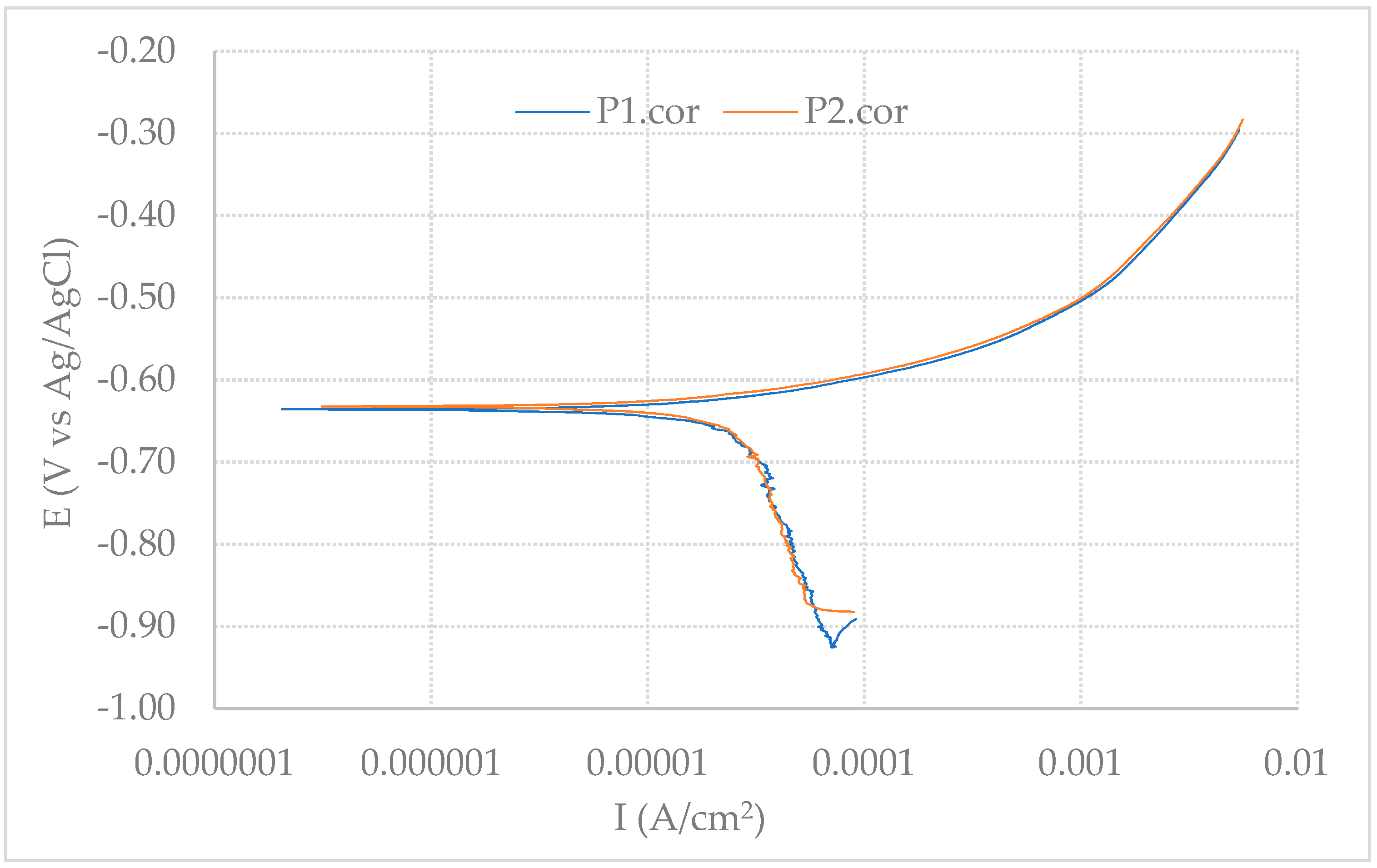
Figure 2 shows polarization curves in semilogarithmic plots for both polished samples P1 and P2. Small (Tafel) slopes in the anodic polarization parts and large slopes in the cathodic polarization parts are observed, approximately 50 mV more active than the corrosion potentials. This means that the corrosion is controlled by the cathodic reactions for the steel in the seawater.
The anodic reaction is iron dissolution [25],
Fe ⇒ Fe2+ +2e
The cathodic reactions include here mainly the reduction of dissolved oxygen,
O2 + 2H2O + 4e ⇒ 4OH
and, possibly, hydrogen evolution in anaerobic environments, e.g., under depsoits and biofilms,
2H+ + 2e ⇒ H2
or,
2H2O + 2e ⇒ H2 + 2OH
Corrosion current density icorr can be calculated from the Tafel slopes in the polarization curves using the Stern–Geary equation [26],
icorr = ba × bc / (2.3·Rp·(ba + bc))
where ba and bc are anodic and cathodic slopes, respectively, in the polarization curves; Rp is the polarization resistance.
The general corrosion rates (CR) can be calculated from the corrosion current densities using the following equation,
CR = 3267·(icorr · Meq)/ρ (mm/y)
where icorr is current density (A/cm2), Meq equivalent mass (g), and ρ density of the materials (g/cm3).
The corrosion potentials and corrosion current densities are presented in Table 4. The average corrosion rate is about 0.3 mm/y. The corresponding corrosion resistance is about 1030 Ω·cm2 (as a reference for further comparison with LPR results).

3.1.2. LPR Measurements

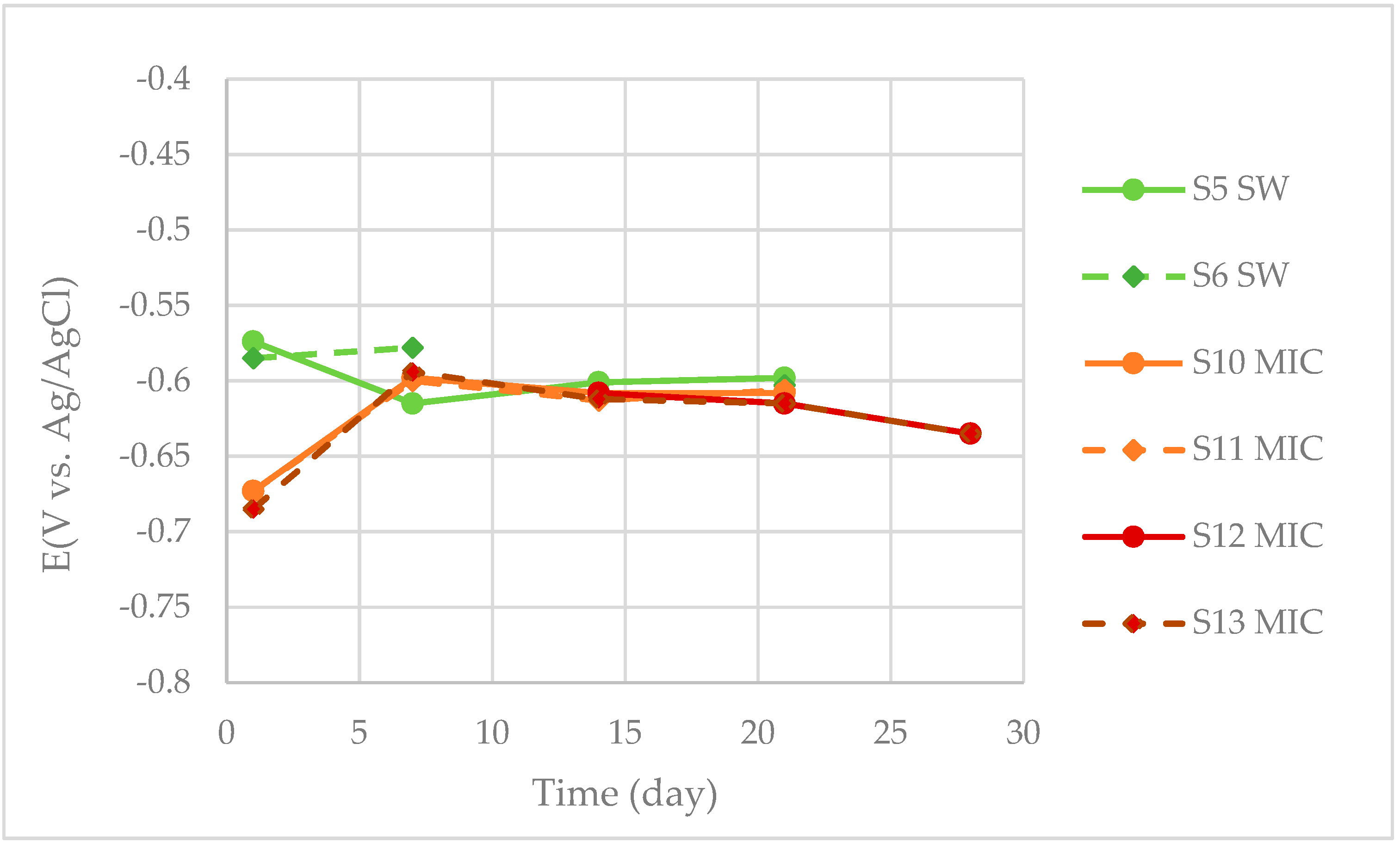
The OCP values as a function of time for the steel in the different electrolytes are shown in Figure 3. The OCP values for the samples in the seawater without bacteria are around −0.6 V. With bacteria, the OCP values moved from −0.67 V to −0.6 V within 7 days. This suggests that the corrosion systems are unstable in the initial period (within 1 week).
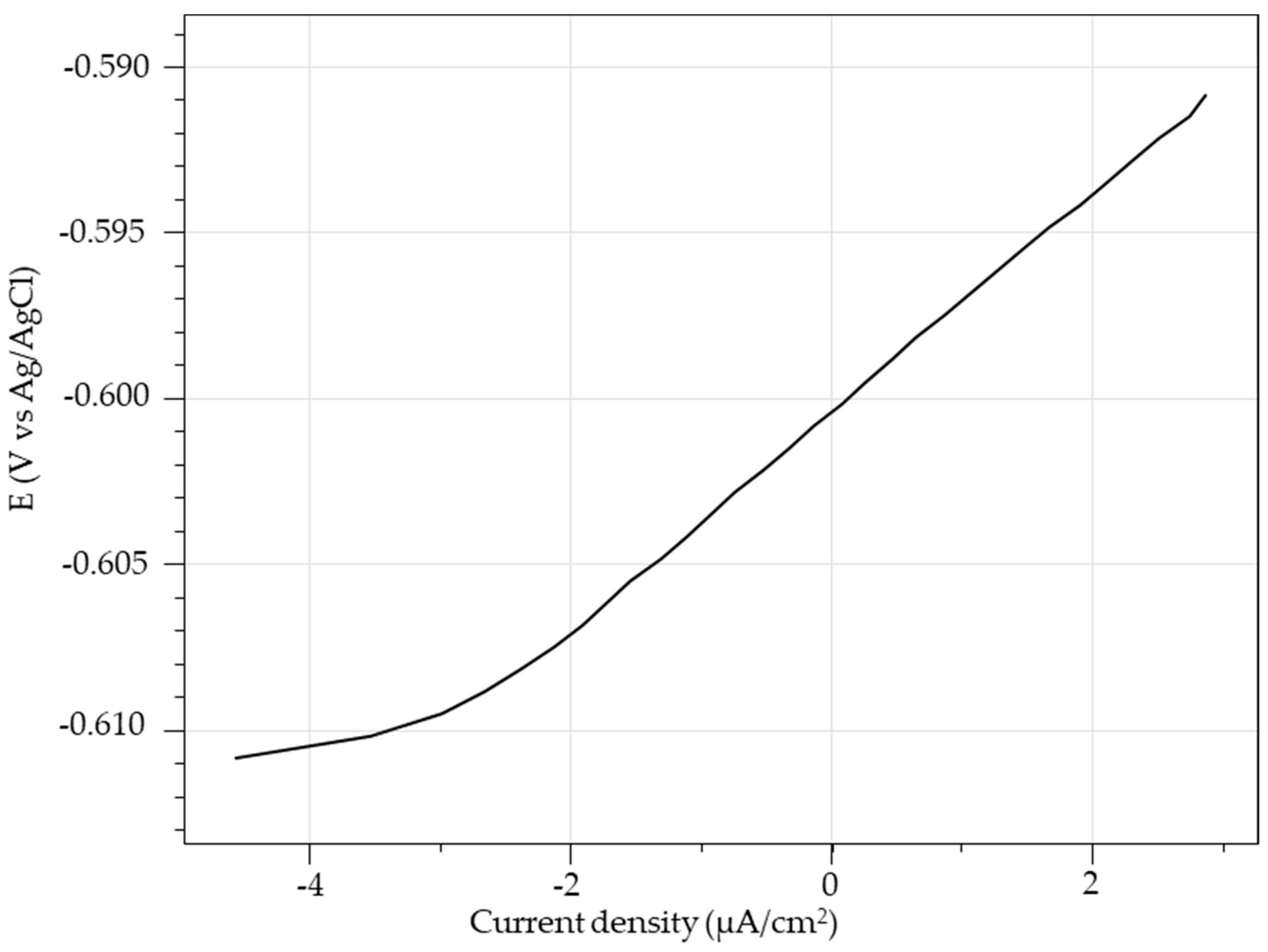
A typical linear polarization (LP) curve for a sample (S5) in SW exposed for 14 days is shown in Figure 4. The LPR (Rp = ΔE/ΔI) was calculated from the line in ±5 mV near the corrosion potential (zero current).
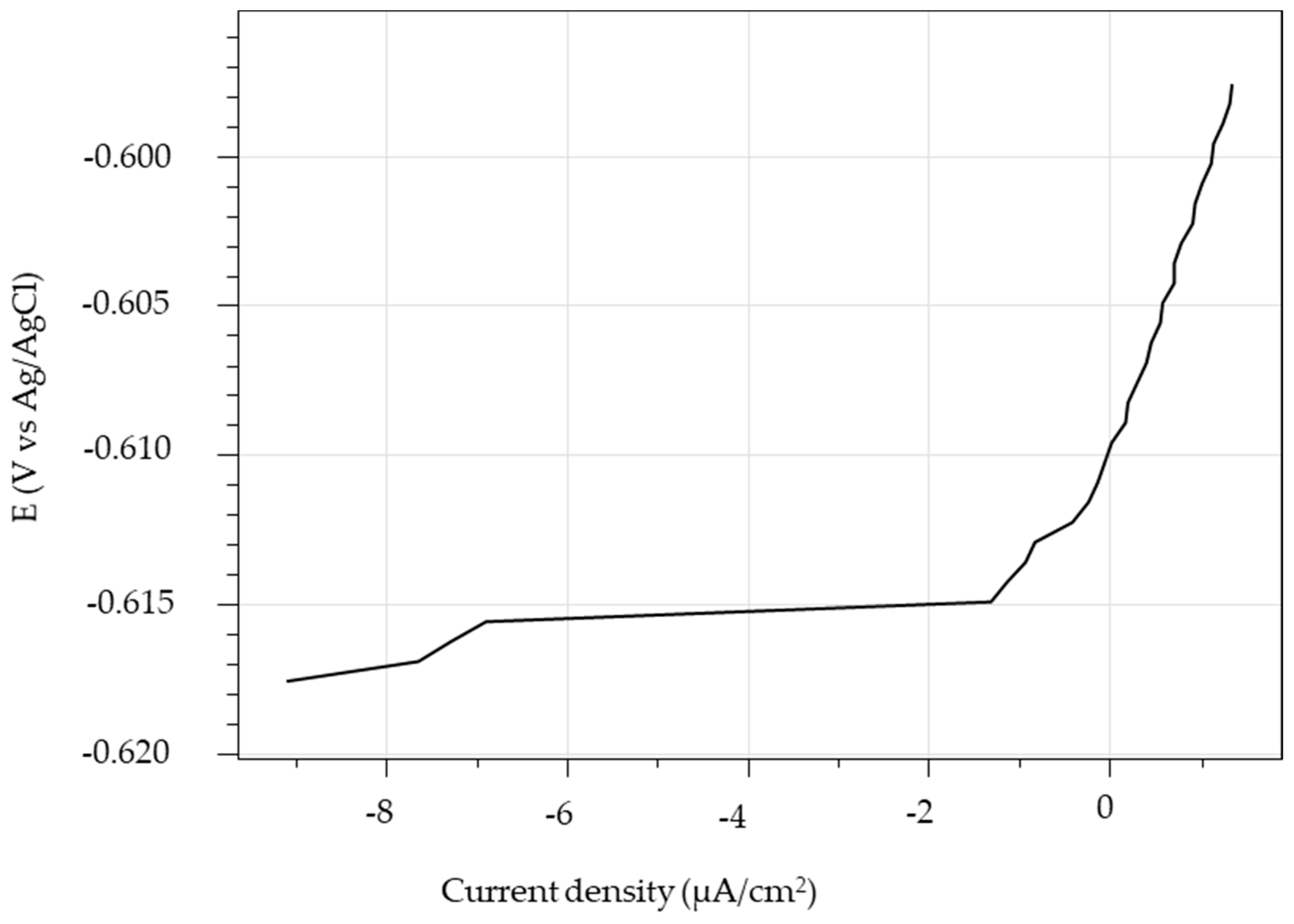
A typical LP curve for a sample (S10) in the SW + bacteria is shown in Figure 5. The linear range of the LP curve near the corrosion potential (−0.61 V) is much narrow compared to that of the S5 in SW near the corrosion potential (zero current). In the presence of bacteria, biofilms formed at the sample surfaces, which exhibit capacitive behaviour. In this case, the corrosion resistance was estimated in the anodic part.
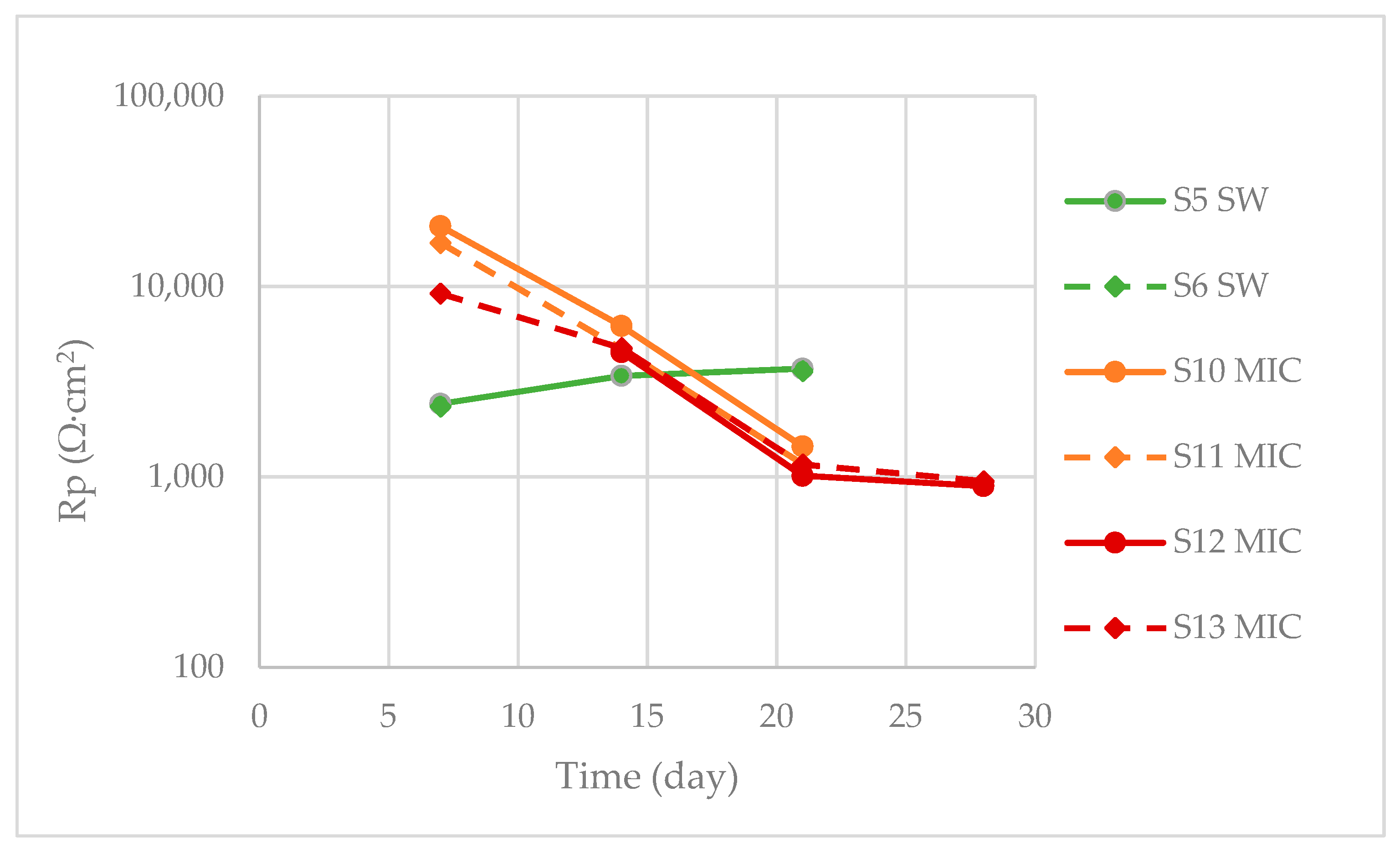
Figure 6 shows the polarization resistance after various exposure times measured for R4 steel samples in SW and in SW+bacteria (MIC). The polarization resistance for the samples in the seawater without bacteria (S5-6 SW) increased from 2.4 kΩ·cm2 to 3.6 kΩ·cm2, while for the samples in the seawater with bacteria (MIC) it decreased from 10 kΩ·cm2 to 1 kΩ·cm2 in 21 days. This indicates that the sample surfaces exposed to seawater with bacteria became more active in 3 weeks, compared to those exposed to seawater only. Originally the designed LPR test duration was for 21 days. Samples S12 and S13 were added and extended the test duration to 28 days to see if their LPR would further decrease in the SW + bacteria. (No sample was added to SW for 28 days, since the LPR in SW did not change much within 21 days).

3.1.3. EIS Measurements

To better study the corrosion resistance, EIS measurements were performed for samples B1–B4. The OCP values for the samples varied around −0.62 V (±0.05 V).
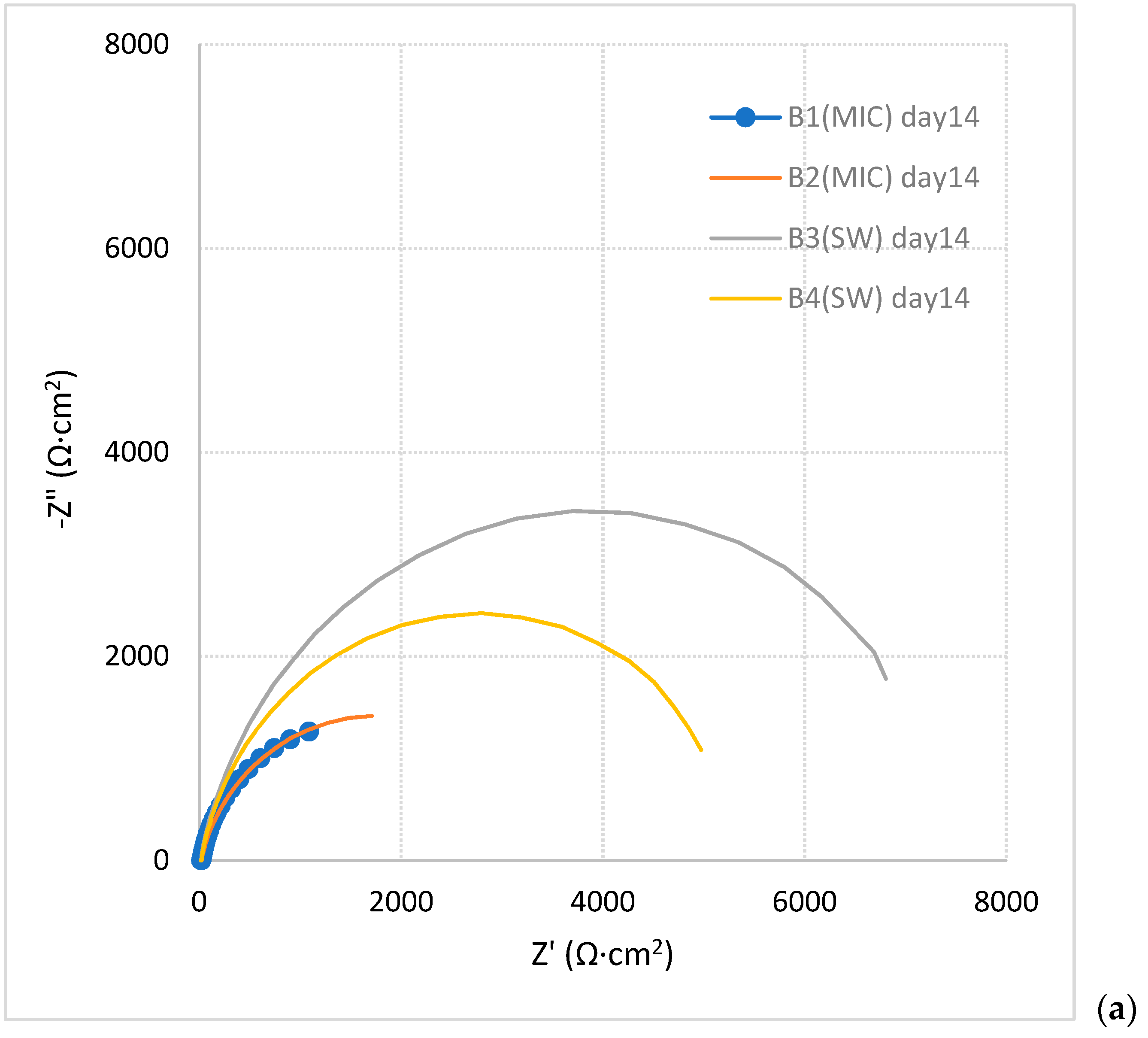
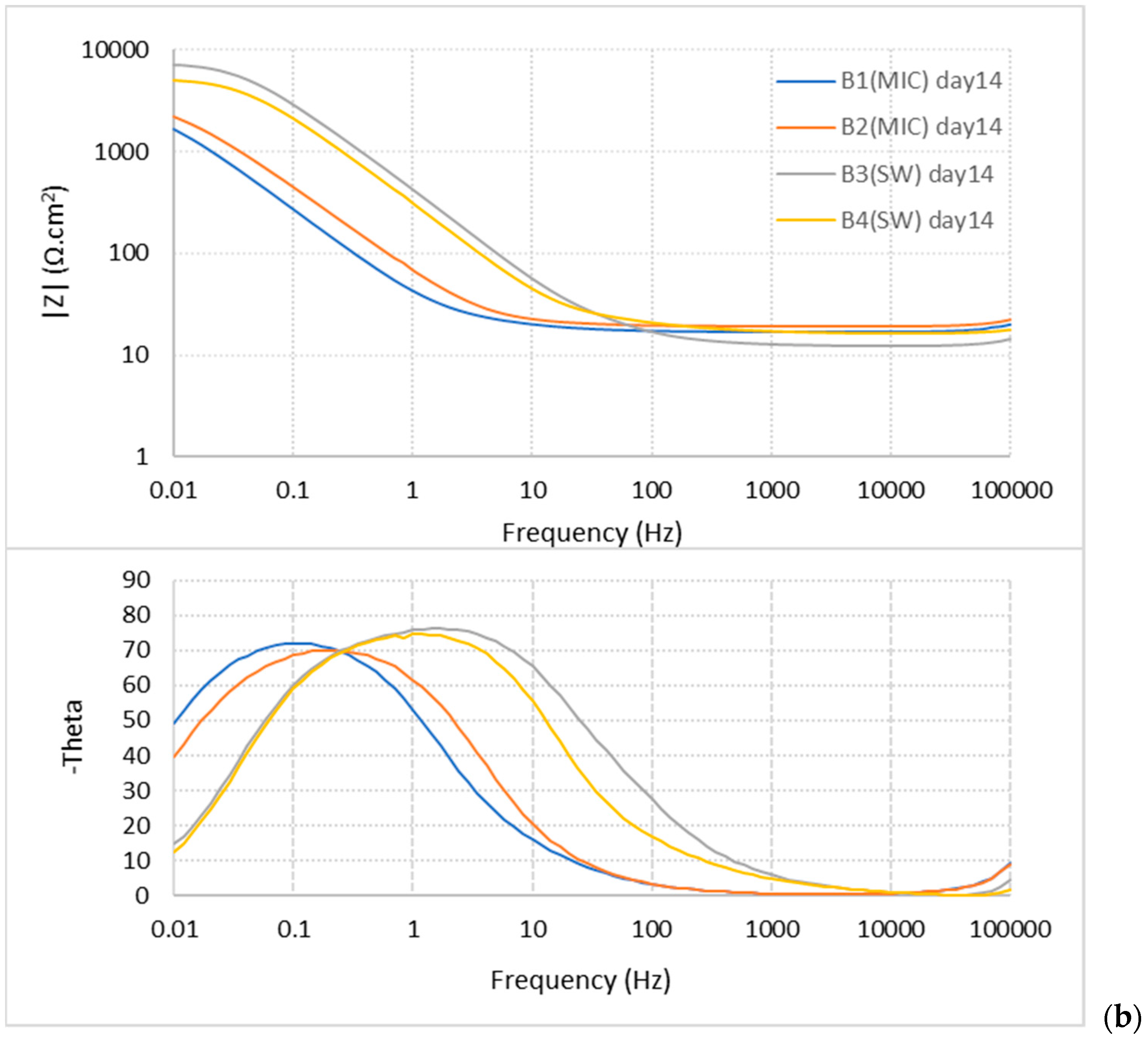
Figure 7 shows the Nyquist plots (a) and Bode plots (b) for the samples exposed to SW and SW+bacteria (MIC) for 14 days. The semicircles of B3 and B4 (in SW) in the Nyquist plots are larger than those of B1 and B2 in SW+bacteria (MIC). The amplitude of the impedance for the samples (B3–B4) in SW is higher than in the SW+bacteria (B1–B2 MIC) at low frequency side (0.01 Hz). The phase peaks shifted to the low-frequency side for the samples in the SW with bacteria, which suggests that the capacitive behaviour is significant.
Figure 8 shows a comparison of Nyquist (a) and Bode (b) impedance plots of samples exposed to SW+bacteria (B1 MIC) and exposed to SW (B3) for different time durations. The impedance module at 0.01 Hz decreased over time in both conditions. The phase angle peak of B1 (MIC) shifted in the low-frequency direction with the increase of duration.
The impedance of the samples at a frequency of 0.01 Hz measured with different exposure durations is presented in Table 5. The electrochemical impedance value at the low-frequency side is related to the corrosion resistance of the steel. The samples exposed to the seawater with microorganisms have smaller impedance values and larger phase angle than without microorganisms.
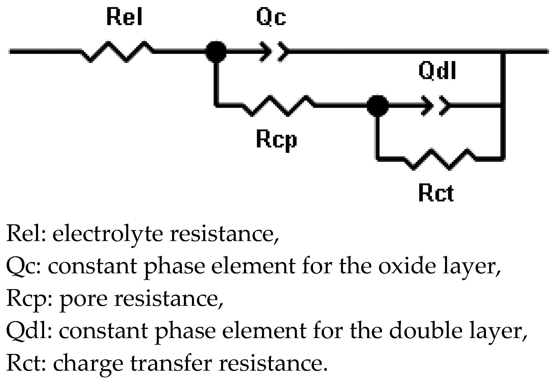
The impedance module can be influenced by resistance, capacitance and even inductance in a corrosion cell. To further analyse the capacitive and resistive behaviour of the corrosion cells, the impedance data were fitted with an equivalent circuit presented in Figure 9. The capacitive elements are submitted by constant phase elements (CPE) Qc and Qdl. The impedance of a CPE can be calculated by the equation:
ZCPE = Y0−1(jω)−n
where Y0 is the admittance constant of the CPE (in sn/Ω); ω is the angular frequency (rad/s); n is the CPE exponent, and n = α/(π/2) (α is the constant phase angle of the CPE). When n = 1, the CPE becomes a pure capacitor [27].
The fitting results are presented in Table 6. The fitting results show that the resistance attributed to the surface layer (Rcp) is very small, compared to the charge transfer resistance Rct. Thus, the polarization resistance is in the same order of the Rct. After exposure for 28 days the corrosion resistance is approaching the same level (3.5 kΩ·cm2) for the samples in SW and in SW+bacteria (MIC). The corrosion resistance was calculated using apparent surface area of the samples, since the real active corrosion area was unknown.
The capacitance was also calculated (C = Y01/n·R(1 − n)/n, [28]), using apparent surface area. The steel samples in SW+bacteria have a larger capacitance of the double layer, than in SW. A larger capacitance results in a lower impedance module at the low-frequency side (Table 5).

3.2. Surface Analysis

3.2.1. Epifluorescence Microscopy

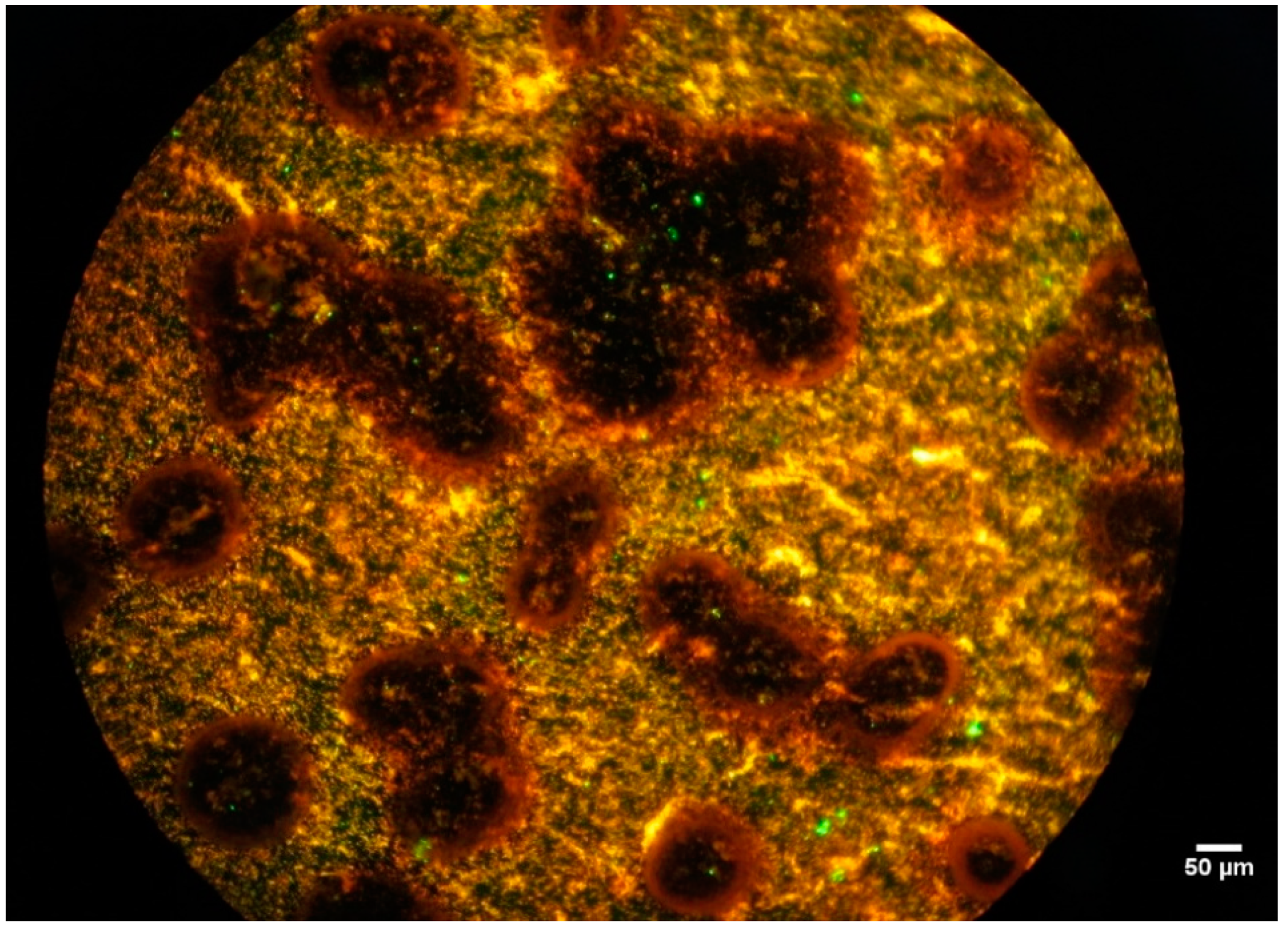
After 7 days of incubation, microorganisms were regularly found on the metal coupon surface. Biofilms covered the damaged area. Active cells (green) were mostly found in and around the pits. The outer part of the biofilm is inactive because the surface was often covered by red (inactive) cells (Figure 10). This means that microorganisms initially attached to the entire surface but could only grow in limited areas where they could form a biofilm. These preferred spots for microbial attachment may contain the right (metallic) nutrients to encourage the growth of bacteria or deliver attractive sites for attachment. The electrons given out by iron at a corrosion spot can be harvested by an SRB film via extracellular electron transfer, which accelerates the cathodic depolarization [29]. In such locations they play a role in the local corrosion process.

3.2.2. Corrosion Morphology

Steel in Seawater without Bacteria

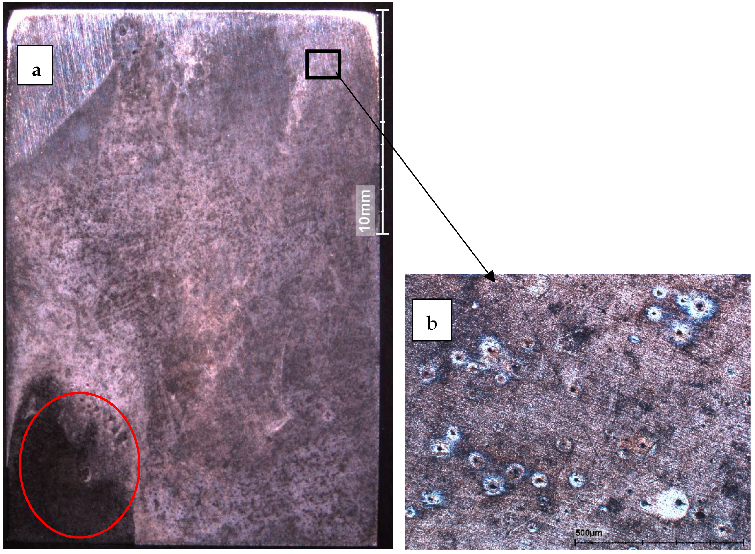
After exposure for 7 days samples S8, S9, S14 and S15 were taken out for surface analysis. After cleaning, the surface of sample S15 is shown in Figure 11a. The upper part of the sample corroded less than the lower part, e.g., little corrosion started on the upper-left corner in the image, where the original polishing pattern can be recognized. This is attributable to the fact that the oxygen is more easily accessible near the water surface than in the lower part. Localized corrosion is visible on the bottom-left corner (Figure 11a), although a large area of the sample S15 showed general corrosion. Small pits are visible in the magnified image Figure 11b. These small pits were in the initial stage. Inside the pits corrosion involved metal hydrolysis and pH decrease. The surrounding area of pits acted as cathodes. The halos surrounding the small pits in the Figure 11b are evidence. The small pits may grow in depth and laterally, becoming big pits or connecting in surface area as general corrosion.
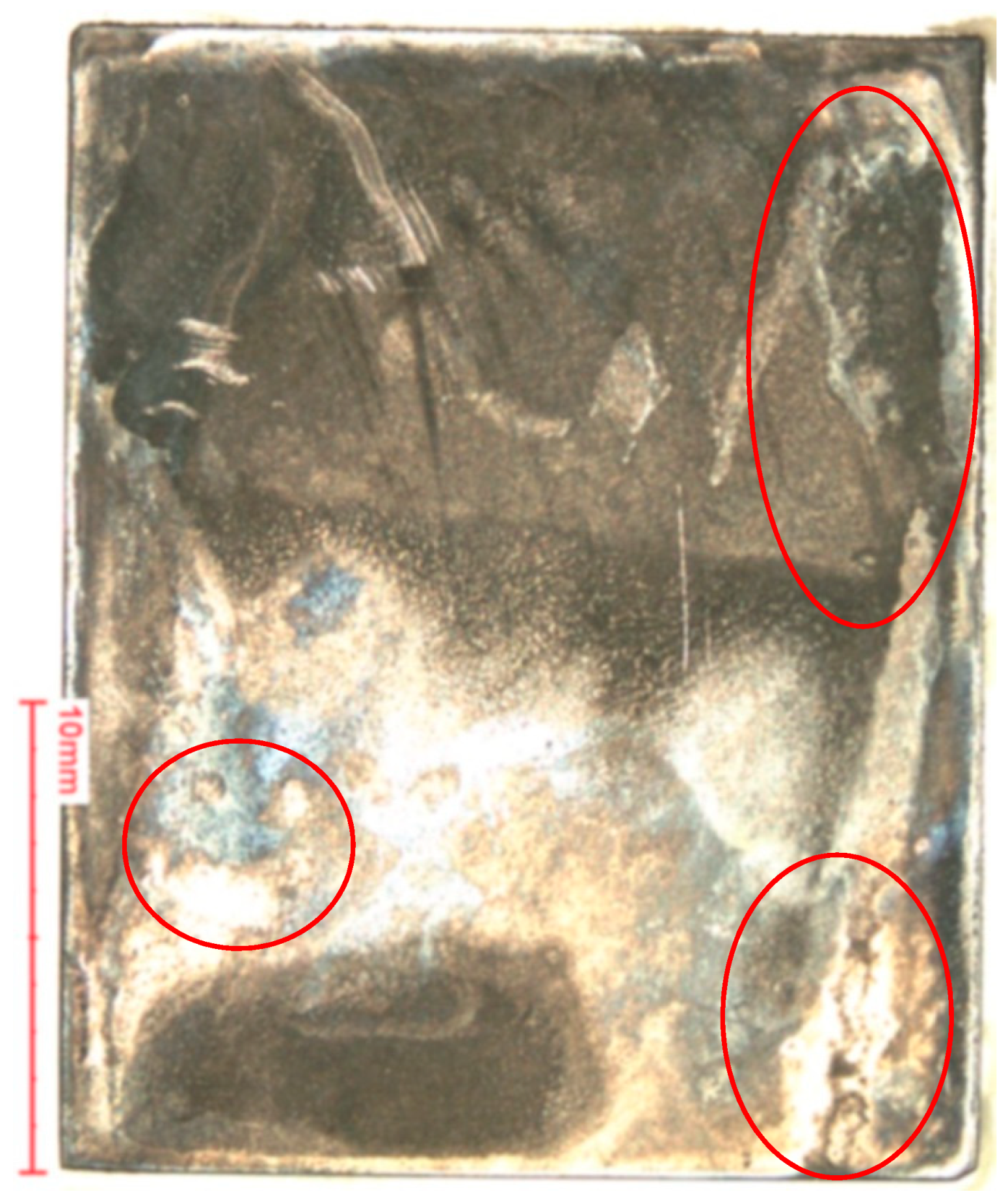
Figure 12 shows an image for the sample B3 exposed to seawater for 28 days after cleaning. The whole surface was corroded. Most areas of the steel surface showed general corrosion. The different colour on the surface is due to the rough surface after corrosion attack and possibly remaining deposits which were not completely removed in the standard cleaning procedure. Localized corrosion spots are visible at the sample surface. The corrosion products rolling down from the upper part affected the corrosion at the lower part of the sample (e.g., lower right corner in Figure 12).
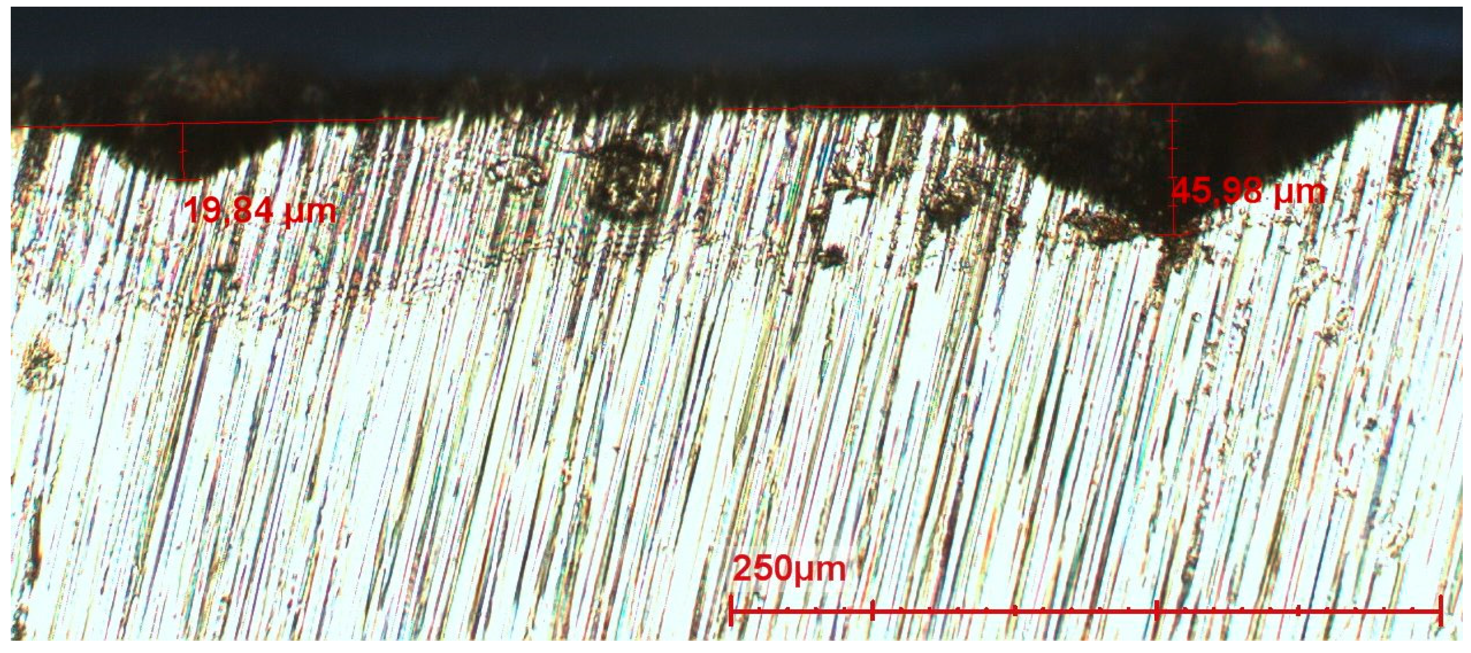
The maximum depth of the pits was measured as 46 µm in sample B3 (Figure 13). It corresponds to 0.6 mm/y, assuming that the local corrosion attack keeps occurring at the same speed.

Steel in Seawater with Bacteria

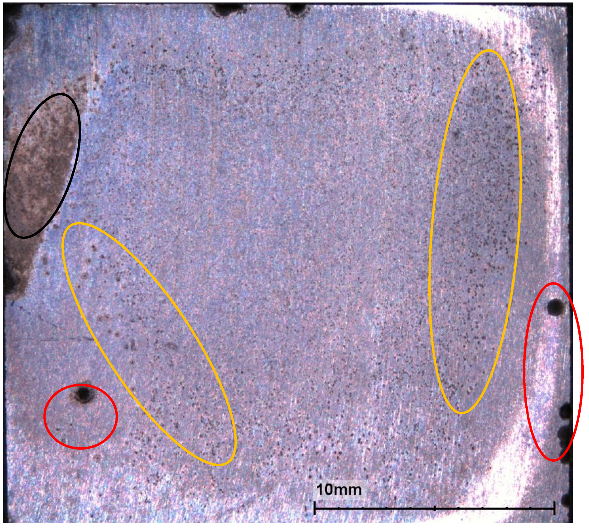
For sample S9 (Figure 14) exposed to SW + bacteria for 7 days, many small pits and a few big pits (about ϕ 0.6 mm) were found. The maximum depth was about 13 µm. More than 80% of the sample surface area showed micro pits; only about 5% surface area showed uniform corrosion; about 10% of the area did not show corrosion.
With the addition of bacteria in SW, typical localized corrosion due to MIC was observed (Figure 15). The corrosion boundary has a round shape. Approximately 40% surface area was corroded. Assuming one third of surface area was corroding, the real corrosion current density would be three times of the average corrosion current density, which means the corrosion rate would be three times of the measured average corrosion rate.
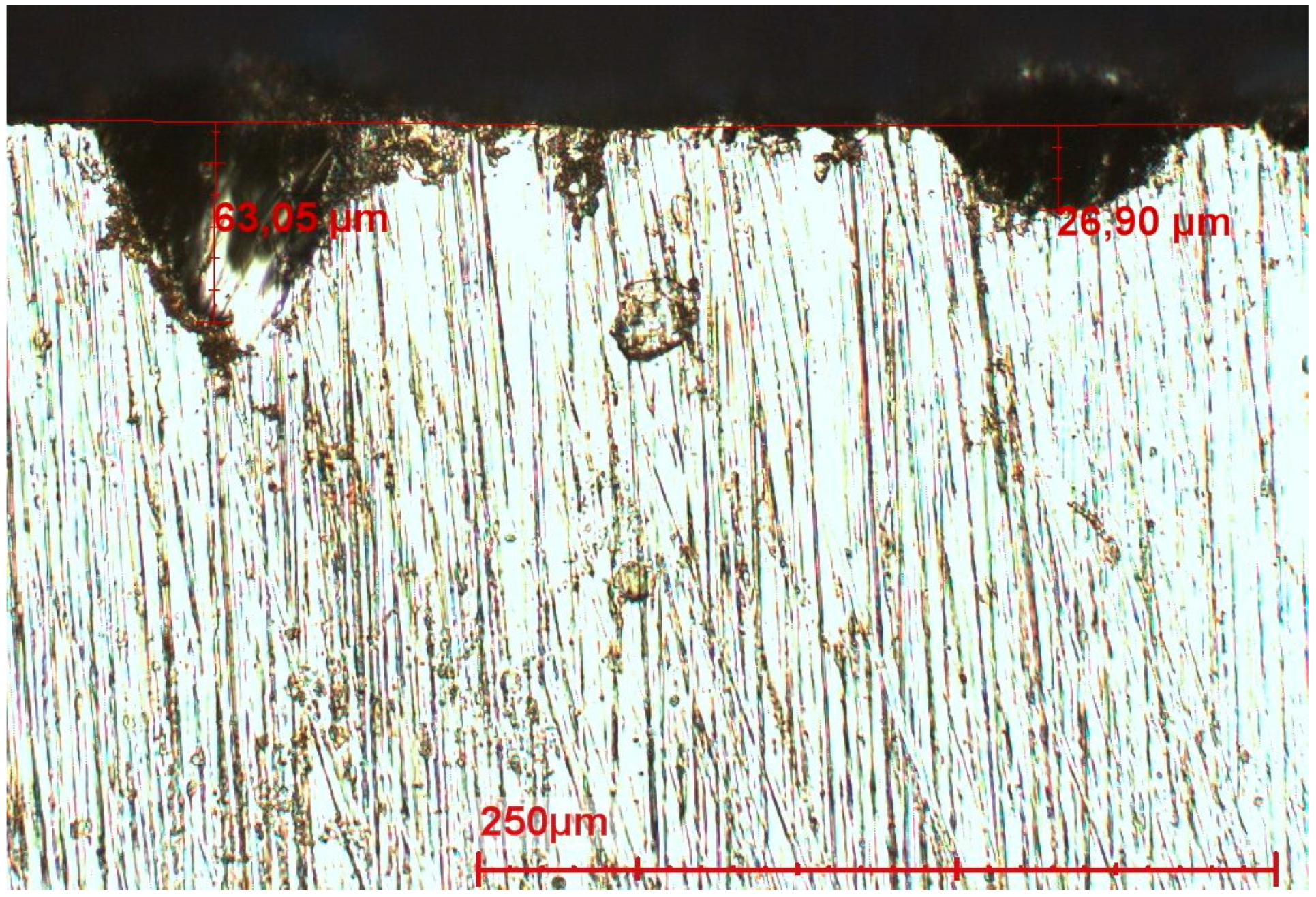
Similar corrosion morphology was found for the samples B1 and B2 exposed to SW+bacteria (MIC) for 28 days. The maximum pit depth is 63 µm (Figure 16), which corresponds to 0.82 mm/y, assuming that the corrosion keeps occurring at the same speed. This corrosion rate is higher than that measured in field assessment (0.53 mm/y in diameter reduction in the worst case), which is attributable to those corrosive bacteria added in the seawater and the temperature in the lab test being higher than in North Sea waters.
The relative percentage of the corroded area and maximum pit depth in samples B1-B4 were evaluated using photo microscopy and are given in Table 7. The areas of micro-pits and macro-pits were estimated by taking a few images and adjusting the black/white contrast. The samples (B1–B2) exposed to SW+bacteria showed a greater percentage of localized corrosion area, while the samples (B3–B4) exposed to SW showed a higher percentage of uniform corrosion and micro-pit area.

3.2.3. Microstructure and Inclusions in the Steel

Figure 17 shows the microstructure of the steel. It shows a typical fine grain microstructure, composed of tempered martensite and bainite.
Inclusions have been found in the steel sample. Figure 18 shows a backscatter image at a cross section (a) and EDS plots at a particle (b) and nearby area (c) for an exposed steel sample (S8). The composition analysed using EDS (see Table 8) indicates that the dark-grey particle in Figure 18a is an MnS inclusion. This inclusion is about 20 µm in length and 5 µm in width. The elements detected at position (3) are related to the composition of the steel matrix.
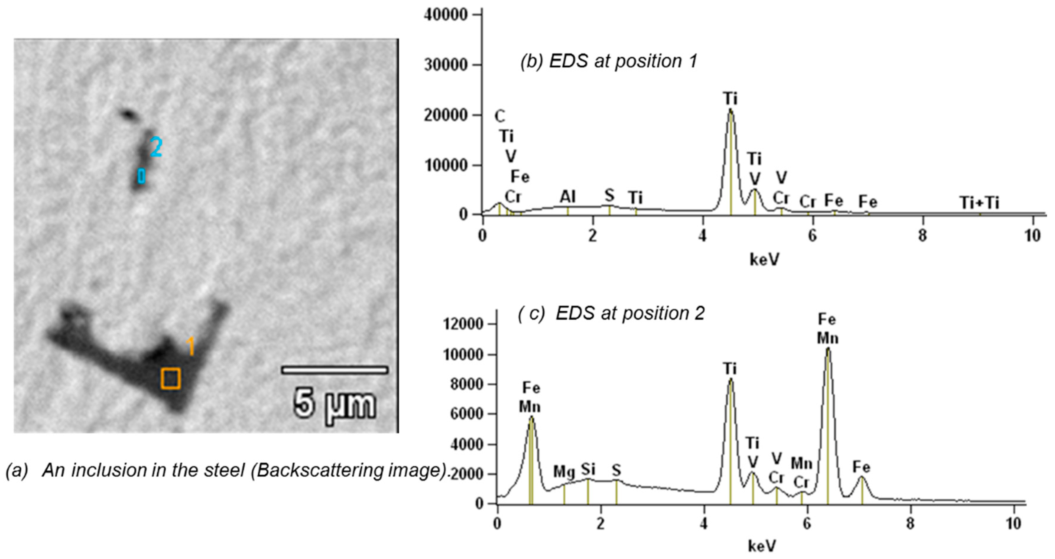
TiVCr-enriched particles were also found in this steel sample (see Figure 19 and Table 9). These particles are known for initiating local corrosion due to their potential difference with regard to that of the surrounding steel matrix.

4. Discussion

Mooring chain steel samples were exposed to artificial seawater and artificial seawater with bacteria for different durations. Different techniques were used to study the localized corrosion phenomena associated with these conditions.
PDP curve measurements show that the fresh steel surface has an average corrosion rate of 0.3 mm/y in seawater (open to air). However, the corrosion rate changes with time because of the surface condition changes over time.
In the presence of micro-organisms, OCP showed a large scatter during the first period (a few days) of exposure. This has to be attributed to irregular attachment of the organisms at the surface and formation of biofilm which disturbs the balance of electrochemical reactions. After 2 to 3 weeks all samples reached a stable value of circa −0.6 VAg/AgCl which is usually measured for this steel in seawater.
The LPR (Rp) measured (in closed vessels) was relatively stable during exposure to SW in the absence of microorganisms. In the closed system the corrosion rate measured using LPR was one third of that measured using PDP curves in an open system. The Rp value 3.6 kΩ·cm2 corresponds with circa 0.1 mm/y corrosion rate for this steel in seawater, in case general corrosion is assumed. On the other hand, in the presence of microorganisms the Rp decreased over time. In all cases good reproducibility was found, but questions were raised about the meaning of the Rp in the case of local corrosion, the subject of this study. This parameter and the way to measure it is completely based on the theory of uniform corrosion. In fact, pits were found in all samples, and that means localized corrosion. The local corrosion rate cannot be established via Rp since the representative area is not clear. If only one third of the surface area is corroding, the real corrosion rate will be three times the measured average corrosion rate.
The reason for applying OCP and LPR in this investigation was that these techniques are relatively easy to perform and therefore suitable to be used for in situ monitoring. However, LPR creates errors due to the non-linearity when biofilms are present at steel surface. EIS gives not only information of polarization resistance, but also information of capacitive behaviour of the surface layers. The polarization resistance measured by EIS was approaching 3.5 kΩ·cm2 in 28 days. The capacitance for the steel in the SW with bacteria was larger than in SW without bacteria, which could be attributable to a larger charged surface area in the presence of biofilm. Thus, EIS gives more information about the surface conditions, although more data fitting is needed. Next to EIS measurements, a detailed pit analysis is also required.
In all cases pits were found in the exposed steel surfaces. A distinction can be made between two different types of pits:
(a)
Relatively small pits which occur in large areas of the steel. Local corrosion attacks initiate at defects such as the grain boundaries or inclusions. According to literature these “micro” pits are formed very quickly after immersion. Most of these pits reach the depth of 100–200 µm and then stop propagating [20,30]. Pits can continue their growth only under a layer of corrosion products or biofilms. The observed pits are the locations where anodic reactions occur, the rest of the surface being the cathodic part. Sometimes after the start of exposure, corrosion products are formed in the pits increasing the electrical resistance and inhibiting the access of oxidizing agents. Then the reactions stop and start elsewhere, but with lower driving forces.
(b)
A limited number of clearly larger pits is found on the surface of all samples. In contrast to the small pits described above, these pits are found in limited locations. These relatively large corrosion spots initiate from small pits and grow in depth and laterally due to high local driving forces such as local metallic inclusions. Relatively large inclusions are found in the steel (MnS and TiVCr, 5–20 µm, see Figure 18 and Figure 19); inclusions are known to have different potentials with regard to the matrix and cause local galvanic corrosion. Therefore, it is obvious that a link exists between the inclusions found and the large pits.
The exposure of coupons without bacteria indicated the aforementioned formation of pits. The steel was fine-grain treated. It contains Al, Ti, V, Cr, Ni and Mo alloy elements, apart from Mn. The microstructure was composed of martensite and bainite. A tiny difference in local chemical difference can initiate small pits as demonstrated in Figure 11. The large pits and the underlying corrosion mechanism is attributed to the exists of inclusions. The pit size depends on the geometry and orientation of the inclusions. The inclusions were not uniformly distributed. The number of inclusions per unit area was not determined in this work. The correlation between the locations of the localized corrosion and inclusions deserves further investigation.
The important question is if the “large” pits will propagate because of MIC or other local causes such as, for example, oxygen depletion (“crevice corrosion”). In the presence of microorganisms, biofilms are formed on the surface. Biofilms can include elements which contribute to the corrosion mechanism but can also function as a barrier to oxygen. One mechanism of MIC is the oxygen differential cell formed under the biofilm which accelerates the local corrosion. Results of epi-fluorescence microscopy showed local concentrations of active organisms (near pits), which implies also local activity. Thus, it is evidence that active organisms preferentially settle in the neighbourhood of pits indicating their possible role in the corrosion process.
Concerning the mechanisms of MIC, a number of theories and models are reported, such as cathodic depolarization theory (CDT), iron sulphide mechanism, anodic depolarization, biomineralization, Romero’s mechanism etc. [31]. However, Blackwood examined the CDT theory and reported that both the CDT and direct electron transfer from the metal into the cell for the role of SRB in the corrosion of carbon steel were incorrect [32]. The MIC process is so complicated that to understand the mechanism needs more effort by materials scientists, electrochemists and biologists working together [32,33].
Results of this study, in particular those of the surface investigation after exposure, prove that surface properties of the steel have an essential role in starting a local corrosion attack. The microstructure and composition heterogeneities at the matrix such as grain boundary (which will be investigated in future) and inclusions generate local corrosion cells because a small difference in composition or microstructures generates an electrochemical difference (e.g., potential difference). These local corrosion cells are likely onsets of local corrosion.

5. Conclusions

From the results described above conclusions can be drawn on the corrosion behaviour of R4 steel in seawater:
(a)
Localized corrosion has been found in the absence as well as in the presence of microorganisms, and occurs from the start of the exposure.
(b)
Inclusions of MnS and TiVCr have been detected in the R4 steel. These inclusions formed during the manufacture of the chain steel have a critical influence on the local corrosion attack.
(c)
With the addition of bacteria, already after 7 days of incubation an active biofilm was detected on the surface of the coupons with favoured locations in and around the pits.
(d)
The localized corrosion rate was as high as 0.82 mm/y in the SW in the presence of bacteria. In the case of local corrosion, applying uniform corrosion measurement techniques and formulas are not considered representative. This paper shows that representative areas have to be introduced to match physical results with the measurements.

Author Contributions

Conceptualization, X.Z. and G.F.; methodology, X.Z., N.N.-H. and G.F.; validation, X.Z. and N.N.-H.; formal analysis, X.Z. and N.N.-H.; investigation, X.Z. and N.N.-H.; resources, M.H.; data curation, X.Z.; writing—original draft preparation, X.Z. and G.F.; writing—review and editing, X.Z., N.N.-H. and M.H.; project administration, M.H.; funding acquisition, G.F. and M.H. All authors have read and agreed to the published version of the manuscript.

Funding

This research was co-funded by TKI Maritiem grant number TKIM-2014-47, Localized Mooring Chain Corrosion (LMCC). The partners are Bluewater, SBM, Bumi Armada, SOFEC, Asian Star, Franklin, Boskalis, Corrosion, TNO, ABS and DNV.

Institutional Review Board Statement

Not applicable.

Informed Consent Statement

Not applicable.

Data Availability Statement

Not applicable.

Acknowledgments

The authors acknowledge the project partners for the financial support, materials supply and fruitful discussions.

Conflicts of Interest

The authors declare no conflict of interest.

References

  1. Ma, K.T.; Shu, H.; Smedley, P.; L’Hostis, D.; Duggal, A. A Historical Review on Integrity Issues of Permanent Mooring Systems; OnePetro: Houston, TX, USA, 2013. [Google Scholar]
  2. Fontaine, E.; Kilner, A.; Carra, C.; Washington, D.; Ma, K.T.; Phadke, A.; Laskowski, D.; Kusinski, G. Industry Survey of Past Failure, Pre-Emptive Replacements and Reported Degradations for Mooring Systems of Floating Production Units; OnePetro: Houston, TX, USA, 2014; p. 14. [Google Scholar]
  3. Zhang, X.; Hoogeland, M. Influence of deformation on corrosion of mooring chain steel in seawater. Mater. Corros. 2019, 70, 962–972. [Google Scholar] [CrossRef]
  4. Melchers, R.E.; Jeffrey, R.; Fontaine, E. Corrosion and the structural safety of FPSO mooring systems in Tropical waters. In Australasian Structural Engineering Conference 2012: The Past, Present and Future of Structural Engineering; Engineers Australia: Barton, Australian, 2012; p. 748. [Google Scholar]
  5. Fontaine, E.; Rosen, J.; Potts, A.; Ma, K.T.; Melchers, R. SCORCH JIP-Feedback on MIC and Pitting Corrosion from Field Recovered Mooring Chain Links. In Proceedings of the Offshore Technology Conference, Houston, TX, USA, 8 May 2014. [Google Scholar]
  6. Little, B.J.; Ray, R.I.; Lee, J.S. Microbiologically influenced corrosion of pilings. VTS Navig. Mooring Berthing 2013, 60, 69–71. [Google Scholar]
  7. GL Noble Denton. Microbiologically Influenced Corrosion of Mooring Systems for Floating Offshore Installations; HSE: London, UK, 2017.
  8. Veritas, D.N. Offshore Mooring Chain; Offshore Standard DNV-OS-E302; DNV: Bærum, Norway, 2013. [Google Scholar]
  9. ABS. Guide for the Certification of Offshore Mooring Chain. 2009. Available online: https://ww2.eagle.org/content/dam/eagle/rules-and-guides/current/survey_and_inspection/39_certificationoffshoremooringchain_2017/Mooring_Chain_Guide_e-May17.pdf (accessed on 11 October 2021).
  10. Vicinay. Haewene Brim Chain Accessment, Report. 2013. Available online: https://vicinayinnovacion.com/case-studies/ (accessed on 11 October 2021).
  11. Fontaine, E.; Potts, A.; Ma, K.T.; Arredondo, A.; Melchers, R.E. SCORCH JIP: Examination and Testing of Severely-Corroded Mooring Chains from West Africa. In Proceedings of the Offshore Technology Conference, Houston, TX, USA, 30 April 2012. [Google Scholar]
  12. DNVGL. Position Mooring, Offshore Standards. 2018. Available online: https://rules.dnv.com/docs/pdf/DNV/os/2018-07/dnvgl-os-e301.pdf (accessed on 11 October 2021).
  13. Shu, H.; Yao, A.; Ma, K.T.; Ma, W.; Miller, J. API RP 2SK 4th Edition-An Updated Stationkeeping Standard for the Global Offshore Environment. In Proceedings of the Offshore Technology Conference, Houston, TX, USA, 30 April 2018. [Google Scholar]
  14. Melchers, R.E.; Chaves, I.A.; Jeffrey, R. A Conceptual Model for the Interaction between Carbon Content and Manganese Sulphide Inclusions in the Short-Term Seawater Corrosion of Low Carbon Steel. Metals 2016, 6, 132. [Google Scholar] [CrossRef] [Green Version]
  15. Man, C.; Dong, C.; Xiao, K.; Yu, Q.; Li, X. The Combined Effect of Chemical and Structural Factors on Pitting Corrosion Induced by MnS-(Cr, Mn, Al)O Duplex Inclusions. Corrosion 2017, 74, 312–325. [Google Scholar] [CrossRef]
  16. Li, T.; Wu, J.; Frankel, G. Localized corrosion: Passive film breakdown vs. Pit growth stability, Part VI: Pit dissolution kinetics of different alloys and a model for pitting and repassivation potentials. Corros. Sci. 2021, 182, 109277. [Google Scholar] [CrossRef]
  17. Avci, R.; Davis, B.; Wolfenden, M.; Beech, I.; Lucas, K.; Paul, D. Mechanism of MnS-mediated pit initiation and propagation in carbon steel in an anaerobic sulfidogenic media. Corros. Sci. 2013, 76, 267–274. [Google Scholar] [CrossRef]
  18. Jeffrey, R.J.; Melchers, R.E. The effect of microbiological involvement on the topography of corroding mild steel in coastal seawater. In Proceedings of the CORROSION 2010, San Antorio, TX, USA, 14 March 2010. [Google Scholar]
  19. Melchers, R.E.; Moan, T.; Gao, Z. Corrosion of working chains continuously immersed in seawater. J. Mar. Sci. Technol. 2007, 12, 102–110. [Google Scholar] [CrossRef]
  20. Melchers, R.E. Pitting corrosion of mild steel in marine immersion environment-Part 1: Maximum pit depth. Corrosion 2014, 60, 824–836. [Google Scholar] [CrossRef]
  21. López-Ortega, A.; Bayón, R.; Pagano, F.; Igartua, A.; Arredondo, A.; Arana, J.; Gonzalez, J.J. Tribocorrosion behaviour of mooring high strength low alloy steels in synthetic seawater. Wear 2015, 338-339, 1–10. [Google Scholar] [CrossRef]
  22. Mansfeld, F.; Little, B. A technical review of electrochemical techniques applied to microbiologically influenced corrosion. Corros. Sci. 1991, 32, 247–272. [Google Scholar] [CrossRef]
  23. Webb, D.J.; Brown, C.M. Epi-Fluorescence Microscopy. In Cell Imaging Techniques; Taatjes, D.J., Roth, J., Eds.; Humana Press: Totowa, NJ, USA, 2012; pp. 29–59. [Google Scholar]
  24. Heyer, A. Microbiological Influenced Corrosion in Ship Ballast Tanks; Haveka Holding, B.V.: Alblasserdam, Zuid-Holland, The Netherlands, 2013; ISBN 978-90-820590-0-7. [Google Scholar]
  25. Uhlig, H.H. Corrosion and Corrosion Control, 2nd ed.; John Wiley & Sons Inc.: Hoboken, NJ, USA, 1971. [Google Scholar]
  26. Stern, M.; Geary, A.L. Electrochemical Polarization 1. Theoretical analysis of the shape and polarization curves. J. Electrochem. Soc. 1957, 104, 56–63. [Google Scholar] [CrossRef]
  27. van Westing, E.P.M.; Ferrari, G.M.; De Wit, J.H.W. The determination of coating performance with impedance measurements -I. Coating polymer properties. Corros. Sci. 1993, 34, 1511–1530. [Google Scholar] [CrossRef]
  28. Buchheit, R.G.; Cunningham, M.; Jensen, H.; Kendig, M.W. A Correlation between Salt Spray and Electrochemical Impedance Spectroscopy Test Results for Conversion-Coated Aluminum Alloys. Corrosion 1998, 54, 61–69. [Google Scholar] [CrossRef]
  29. Gu, T.; Jia, R.; Unsal, T.; Xu, D. Toward a better understanding of microbiologically influenced corrosion caused by sulfate reducing bacteria. J. Mater. Sci. Technol. 2018, 35, 631–636. [Google Scholar] [CrossRef]
  30. Butler, G.; Stretton, P.; Beynon, J.G. Initiation and growth of pits on high-purity iron and its alloys with chromium and copper in neutral chloride solutions. Br. Corros. J. 1972, 7, 168–173. [Google Scholar] [CrossRef]
  31. Khan, M.A.A.; Hussain, M.; Djavanroodi, F. Microbiologically influenced corrosion in oil and gas industries: A review. Int. J. Corros. Scale Inhib. 2021, 10, 80–106. [Google Scholar] [CrossRef]
  32. Blackwood, D.J. An Electrochemist Perspective of Microbiologically Influenced Corrosion. Corros. Mater. Degrad. 2018, 1, 5. [Google Scholar] [CrossRef] [Green Version]
  33. Little, B.; Blackwood, D.; Hinks, J.; Lauro, F.; Marsili, E.; Okamoto, A.; Rice, S.; Wade, S.; Flemming, H.-C. Microbially influenced corrosion—Any progress? Corros. Sci. 2020, 170, 108641. [Google Scholar] [CrossRef]
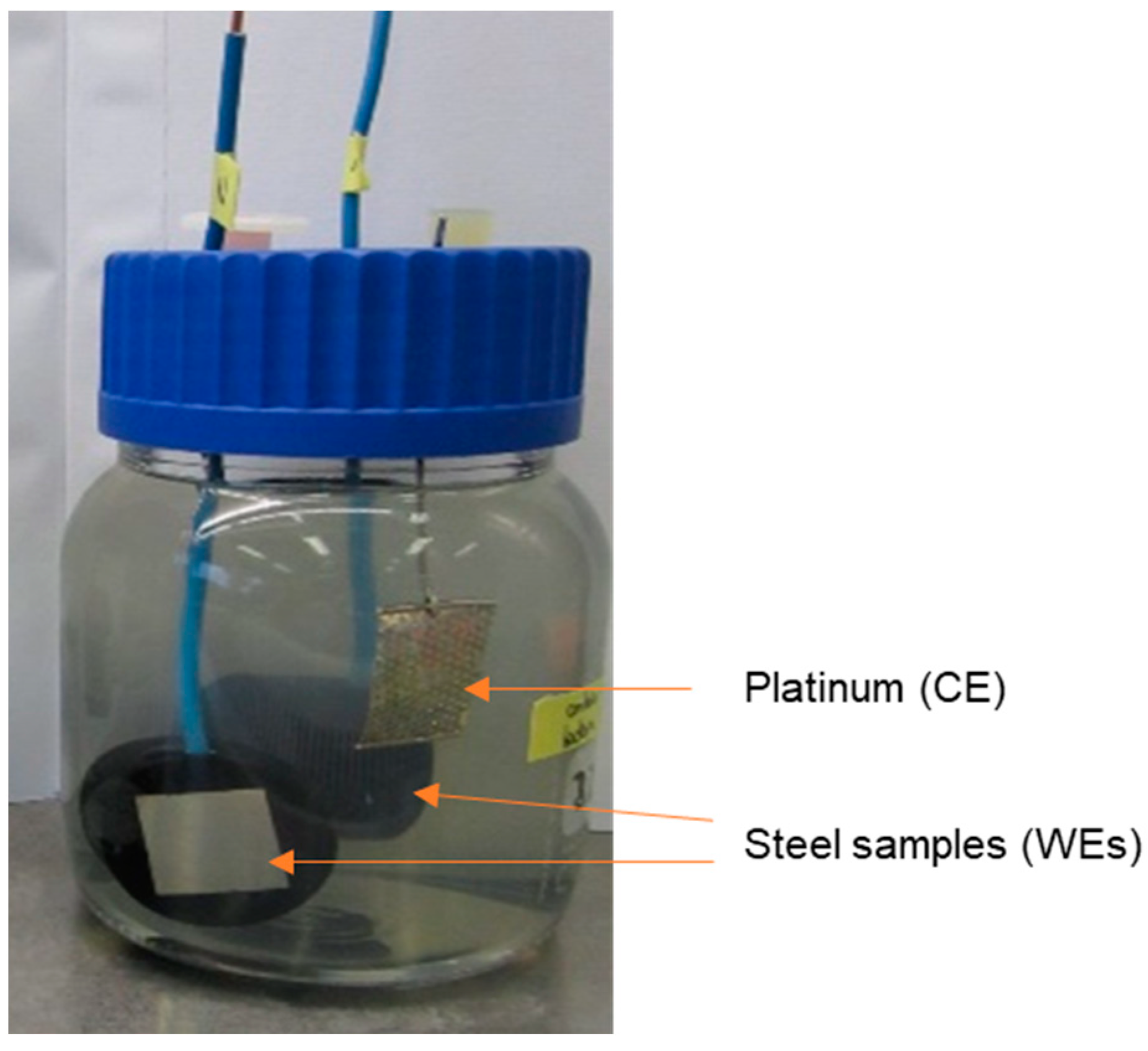
Figure 1. A typical sample exposure vessel for linear polarization resistance (LPR) and electrochemical impedance spectroscopy (EIS) measurements.
Cmd 03 00004 g001
Figure 2. Polarization curves for the polished samples in artificial seawater (open to air) at 20 °C.
Cmd 03 00004 g002
Figure 3. Open circuit potential (OCP) values as a function of time measured for R4 steel samples in seawater with and without bacteria.
Cmd 03 00004 g003
Figure 4. A typical linear polarization curve for a sample (S5) in seawater (SW), exposed for 14 days.
Cmd 03 00004 g004
Figure 5. A typical polarization curve for a sample (S10) in SW+bacteria (MIC), exposed for 14 days.
Cmd 03 00004 g005
Figure 6. Polarization resistance measured by LPR as a function of time measured for R4 steel samples in seawater with and without bacteria. S5 and S6 in SW showed the same LPR values.
Cmd 03 00004 g006
Figure 7. Nyquist (a) and Bode (b) impedance plots for samples exposed to SW (B3, B4) and to SW + bacteria (B1, B2 MIC) for 14 days.
Cmd 03 00004 g007aCmd 03 00004 g007b
Figure 8. A comparison of Nyquist (a) Bode (b) impedance plots of samples exposed to SW + bacteria (B1 (MIC)) and exposed to SW (B3) for different time durations.
Cmd 03 00004 g008
Figure 9. Equivalent circuit used for fitting the impedance data.
Cmd 03 00004 g009
Figure 10. Micrograph of metal coupon (S9) after 7 days of exposure (before cleaning). A biofilm was detected on the metal coupon surface. Active cells (green) were mostly found in the pits whereas red (inactive) cells were located around the pits.
Cmd 03 00004 g010
Figure 11. An image for the sample S15 exposed to seawater for 7 days (after cleaning the surface). Local corrosion attack was found near the bottom-left corner (a) and small pits near the upper-right corner zoomed in the image (b).
Cmd 03 00004 g011
Figure 12. An image for sample B3 exposed to seawater for 28 days (after cleaning). Localized corrosion attacks were found in the steel (red circle). The lower part of the steel sample was affected by corrosion products rolling down.
Cmd 03 00004 g012
Figure 13. Cross-sectional view at pits for samples B3 in SW for 28 days.
Cmd 03 00004 g013
Figure 14. An image for the sample S9 exposed to SW + bacteria for 7 days (after cleaning the surface). Many small pits (yellow, diameter < 0.1 mm, >80% area) and a few big pits (red, diameter > 0.5 mm, ~3% area) were in the steel. Uniform corrosion took place in a small area (black, ~5% area).
Cmd 03 00004 g014
Figure 15. An image of sample S13 exposed to seawater with bacteria for 28 days (after cleaning). Half of the surface area was attacked by local corrosion.
Cmd 03 00004 g015
Figure 16. Cross-sectional view at two pits for sample B2 after exposure to the SW + bacteria for 28 days. The maximum pit depth is 63 µm.
Cmd 03 00004 g016
Figure 17. Microstructure of the chain grade R4 steel, composed of tempered martensite and bainite.
Cmd 03 00004 g017
Figure 18. An inclusion (backscattering image (a), EDS plots in the position 1 (b) and at position 3 (c) for an exposed sample (S8) after exposure to seawater without bacteria for 7 days.
Cmd 03 00004 g018
Figure 19. An inclusion (backscattering image (a), EDS plots in the position 1 (b) and at position 3 (c) for an exposed sample (S8) after exposure to seawater without bacteria for 7 days.
Cmd 03 00004 g019
Table 1. Nominal composition of the grade R4 steel in wt.% (the rest is Fe).
QR4CMnSiPSNiMoCrAlCuSnVTiAs
min.0.180.850.15 0.500.200.900.015 0.04
max.0.241.200.350.0200.0150.800.401.250.0400.250.0300.100.0150.025
Table 2. Experimental methods and conditions.
SamplesSWSW + Bacteria (MIC)Test Duration (Day)
P1, P2PDP
B1, B2 LPR + EIS28
B3, B4LPR + EIS 28
S5, S6LPR 21
S8, S9 LPR7
S10, S11 LPR21
S12, S13 LPR28
S14, S15LPR 7
Table 3. Chemical concentration (g/L) in the artificial seawater.
NaClMgCl2CaCl2Na2SO4KClNaHCO3KBrH3BO3NaFSrCl2YeastLactate
23.935.071.154.010.680.1970.0990. 030.010.140.014.2 mL
Table 4. Corrosion potentials and corrosion rates for the polished samples in seawater.
SteelEc (V)icorr (µA/cm2)ba (mV/dec)bc (mV/dec)CR (mm/y)
P1−0.6426686180.30
P2−0.6325656760.29
Table 5. Impedance values and phase angles at 0.01 Hz.
SampleSolutionTime (Day)|Z| (Ω·cm2)Theta
B1SW + bacteria141629−49
21980−66
28392−73.2
B2SW + bacteria142268−40
21478−74.6
28460−73
B3SW147036−14.7
215038−12.5
283227−14.9
B4SW145093−12.3
213880−13
283275−16
Table 6. Parameters and fitting results of the impedance data using an equivalent circuit, R in Ω·cm2 and C in (F·cm−2).
SampleTime (Day)Ccn1RcpCdln2Rctχ2 (×10−4)
B1 (MIC)140.002270.893150.001250.8993210.80.6
210.006730.869170.002110.99984328.61.2
280.01239130.010070.8683624.83
B2 (MIC)140.00104130.000520.80836540.9
210.007540.93140.013780.9324216.58
280.015900.99770.004100.8144477.51.8
B3 (SW)140.000200.88390.000070.9657825.54.5
210.000230.932140.000180.9225494.38
280.000380.94100.000300.933487.45.9
B4 (SW)140.000150.872120.000190.9435512.65.2
210.000210.922120.000310.9314222.64.4
280.000430.931110.000380.9335693.6
Table 7. Percentage of corrosion area (%) and maximum pit depth of samples B1–B4.
SampleConditionTime (Day)Uniform
Corrosion
Macro-PitsMicro-PitsCorrosion Products
Affected Area
Intact
Area
Maximum
Pit Depth (µm)
B1MIC28-3070--42
B2MIC28-2070-1063
B3SW2830105010-46
B4SW28401050--39
Table 8. Element percentage (wt. %) measured at positions in Figure 18a.
ElementSiSCaCrMnFeNi
Position 16.238.00.2 53.22.4
Position 30.50.4 2.01.295.30.6
Table 9. Element percentage (wt.%) measured at positions in Figure 19a.
ElementCMgAlSiSTiVCrMnFe
Point 19.1 0.1 1.075.08.63.5 2.7
Point 2 0.2 0.30.524.61.71.81.269.7
Publisher’s Note: MDPI stays neutral with regard to jurisdictional claims in published maps and institutional affiliations.