Article

Comparative Study of Chloride and Fluoride Induced Aluminum Pad Corrosion in Wire-Bonded Device Packaging Assembly

Interfacial Electrochemistry and Materials Research Lab, University of North Texas, Denton, TX 76203, USA
*
Author to whom correspondence should be addressed.
Corros. Mater. Degrad. 2021, 2(3), 447-460; https://doi.org/10.3390/cmd2030023
Submission received: 21 June 2021 / Revised: 27 July 2021 / Accepted: 5 August 2021 / Published: 11 August 2021

Abstract

:
The introduction of copper as wire bonding material brings about a new challenge of aluminum bond pad bimetallic corrosion at the copper/aluminum galvanic interface. Aluminum is well known to undergo pitting corrosion under halide-contaminated environments, even in slightly acidic conditions. This paper aims to study the corrosion morphology and progression of aluminum influenced by different halide contaminations in the presence and absence of galvanic contact with copper. We used a new corrosion characterization platform of the micropattern corrosion screening to simulate the copper wire bonding on the aluminum bond pad. The corrosion screening data and subsequent SEM–EDX analyses showed a striking difference in morphology and progression between chloride-induced and fluoride-induced aluminum corrosion. The corrosion products formed play a vital role in the resulting morphology and in sustaining further aluminum corrosion.

1. Introduction

Our day-to-day life extensively uses wire-bonded electronic devices (WBDs) for various applications in medicine, communication, transportation, and so on. The cost-effective nature of wire-bonded devices rises due to their flexible interconnect assembly technology. Copper (Cu) has replaced gold (Au) as wire bonder material due to its several advantages, such as lower cost, higher Young’s modulus, and lower resistivity [1]. However, Cu wiring has introduced reliability issues, such as corrosion of the aluminum (Al) bond pad, leading to WBD failure. According to reports, halides such as chloride (Cl) and fluoride (F) can corrode Al even at low ppm concentrations, causing the Cu wire to lift off from the Al pad [2,3,4,5]. The Cl contaminant in packaging is usually from epoxy molding compounds (EMCs), which can initiate corrosion in the presence of moisture. F contaminants mainly come from plasma processes, leading to non-stick-on-pad (NSOP) reliability issues [6].
The Al surface can undergo severe pitting due to halide interaction, resulting in cracks and dendrites. The commonly accepted mechanism is that the halide ion attacks the Al surface by penetrating the passivating oxide layer, causing continuous pitting due to the localized cells on the surface [7,8,9]. Since the introduction of thin-film Al in microelectronics, wide-scale investigation of the corrosion properties in thin-film structures has been ongoing. The corrosion of Cu/Al (Cu bimetallic contact with Al) WBD in Cl gained more attention in the past decade because they are the most common contaminants in the microelectronic manufacturing environment [10,11,12]. However, the exact mechanism of how the F corrosion proceeds have not yet been reported and studied in detail. In addition, systematic exploration of the halide corrosion in Al thin film in the presence of bimetallic contact with Cu is absent.
Previous investigations reported that the intermetallic compounds (IMCs) formed between Cu and Al were the main reason for the failure of WBD under moisture and halide contaminants [13,14,15]. However, the severity of Al corrosion depends on several factors, such as halide concentration, pH, nature of the corroding cell, bimetallic contacts, and so on. Halides, being the most common contaminants found in the packaging line, poses a significant threat to the reliability of Al bond pads even in slightly acidic conditions. The approach for this study focuses on the peripheral Cu/Al bimetallic contact rather than the buried IMCs. The corrosion mechanism of the Cu/Al bimetallic contact in the periphery of WBD due to Cl contaminant was reported before by Ross et al. [16]. This study focuses on the corrosion morphology and proposes F contaminant mechanism related to WBD and compares them with Cl contaminant corrosion.
This research investigates the corrosion of Al (with 0.5 wt% Cu) immersed in dilute Cl and F solutions (ppm level) at a slightly acidic pH (pH = 5). pH 5 was chosen for corrosion screening to simulate the slightly acidic nature of EMCs with moisture. A new in situ corrosion study platform termed micropattern immersion corrosion screening was developed to study the corrosion progression in real time. The micropattern was created by sputtering Cu microdots on Al to simulate the Cu wire on the Al bond pad interface serving as a quick and cost-effective way of studying different corrosion conditions and corrosion inhibitors without the actual usage of a real WBD [17]. In situ corrosion progression insights lead to the development of the corrosion mechanism and corrosion inhibition strategies. Immersion screening metrology may have a different kinetic preference mechanism from actual industrial corrosion testing, such as HAST (highly accelerated stress testing), usually performed in molded encapsulated devices. This testing metrology exposes the Al surface to a more severe corrosive condition than the industry testing due to the complete immersion of devices in 100% moisture with halide contaminants without ion traps typically present in the EMCs to reduce corrosion contaminant delivery to the bond pad [18].
This article discusses the difference in the corrosion progression of Al thin film in the presence and absence of Cu bimetallic contact immersed in Cl and F environments. In situ monitoring of the corrosion provided crucial understandings of the different mechanisms between the Cl and F environment. This mechanistic understanding holds the key to deciphering the corrosion cycle, mitigating different Al pad corrosion types, and preventing the Cu wire lift-off.

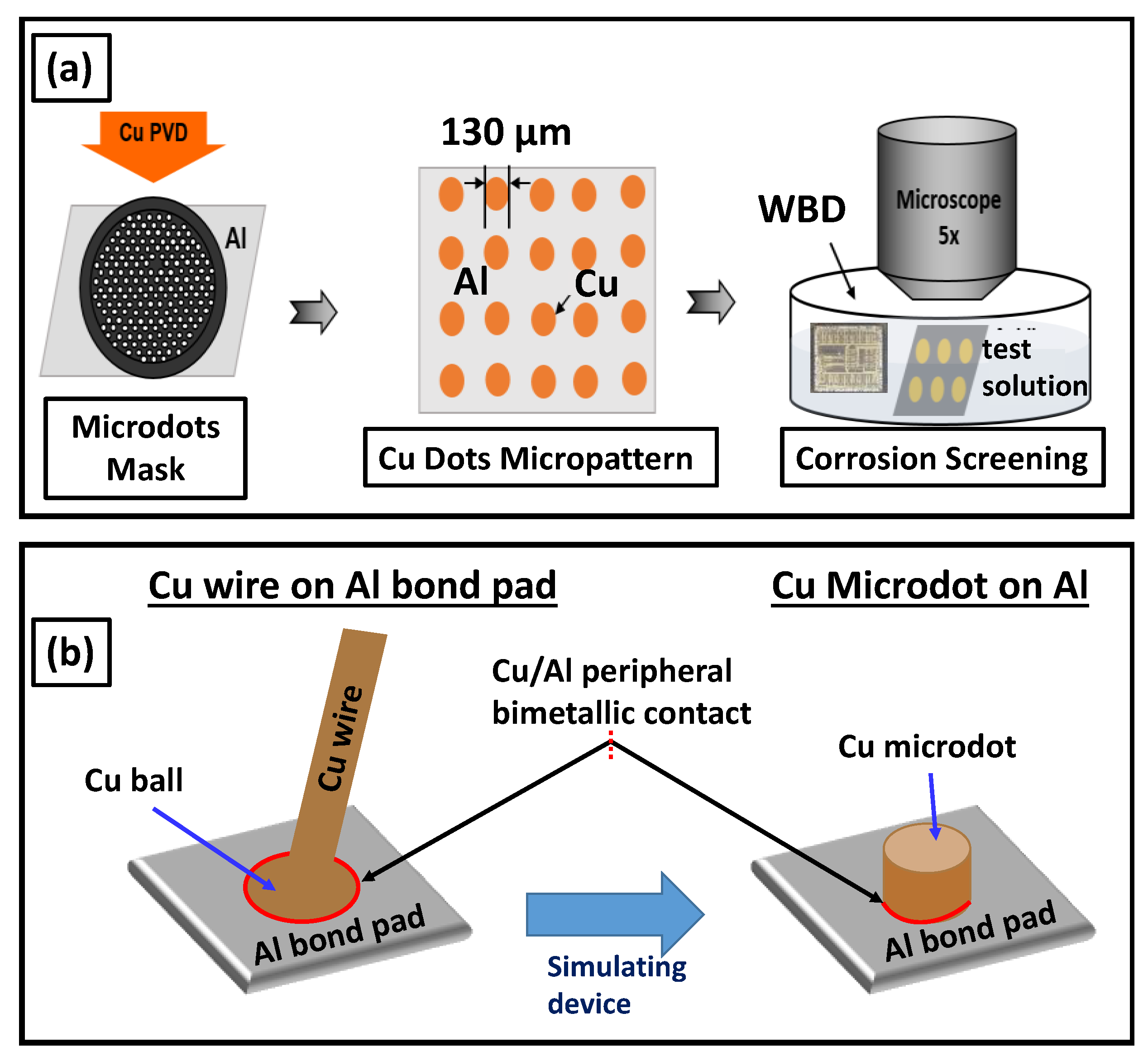
2. Materials and Methods

The Al samples mentioned in this study refer to Al alloyed with 0.5 wt% Cu. Corrosion screening was carried out by studying the real-time progression of corrosion under the microscope. The detailed procedures for the micropattern screening technique were described in this publication [17]. The micropatterns used in this study are shown in the Figure 1 schematic. The micropatterns were created by sputtering 130 µm diameter Cu microdots onto an Al (with 0.5 wt% Cu) substrate to imitate the Cu wire bonding to the Al bond pad scenario. The thickness of the dots ranged from 50 to 500 nm. A Nikon LV-150 optical microscope was used for monitoring and recording the corrosion progression. All chemicals were reagent grade and used as obtained from Merck. The dilute halide solutions were made by a series of dilutions from a 1000 ppm stock solution of NaCl and NaF, respectively, for Cl and F solutions. Ultrapure water from Millipore Sigma (resistivity, 18.1 MΩ, Burlington, VT, USA) was used in making solutions, rinsing samples, and performing dilutions. All pH adjustments were made using H2SO4 and NaOH (both reagent grades from Merck, Burlington, NJ, USA). All samples were rinsed with UPW before surface analysis. EM–EDX measurements of corroded samples were obtained from FEI Quanta ESEM scanning electron microscopes (Hillsboro, OR, USA) to study surface products and surface morphology. The gas evolution during corrosion was investigated by the method of headspace chromatography using a Thermo Finnigan gas chromatograph–mass spectrometer (GC–MS, Waltham, MA, USA). The WBD devices were immersed in Cl and F conditions separately in a silicone-sealed flask for more than 24 h, and the headspace gas was transferred to a GC–MS analyzer for composition identification. Potentiodynamic polarization was carried out using a CHI 760D potentiostat (Austin, TX, USA) in a three-electrode system (Al as the working electrode). Electrochemical studies were carried out in samples with a controlled area of 0.3 cm2 exposure. The galvanic coupling current was measured using two electrodes (Cu and Al) immersed in the solution and electrically connected to a Keithley 2400 source meter (Solon, OH, USA). The chemical composition of the surface products was investigated using PHI 5000 VersaProbe Scanning XPS (Chanhassen, MN, USA).

3. Results and Discussion

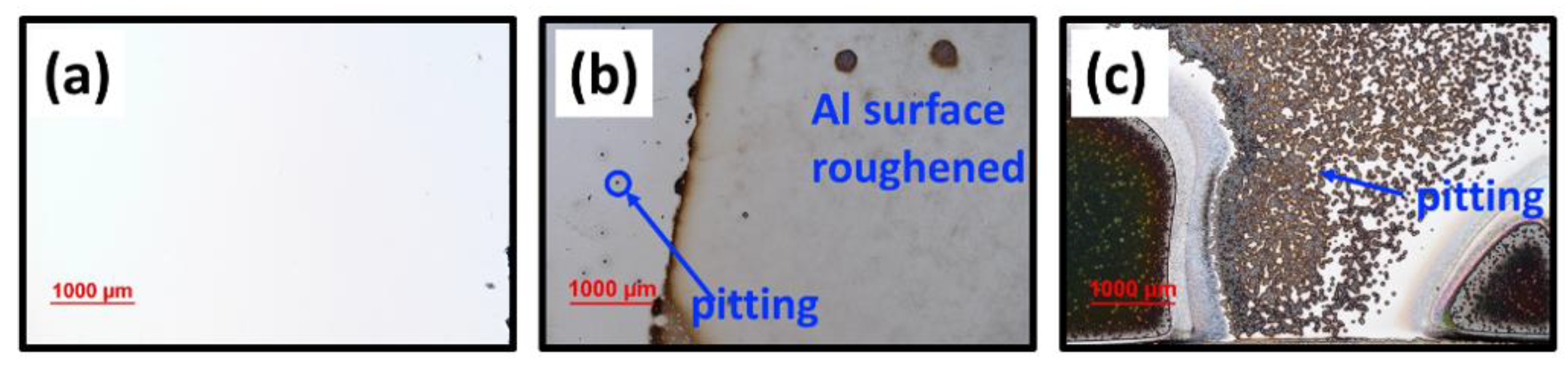
3.1. Halide-Induced Corrosion on Blanket Al in the Absence of Cu Bimetallic Contact

Figure 2 shows the corrosion morphology of blanket Al substrates immersed in solutions of 5 ppm Cl and 5 ppm F at pH 5. In Figure 2b, surface roughening was observed on the Al substrate with minor pitting after 24 h immersion of Al in 5 ppm Cl solution at pH 5. The corrosion progressed with major surface roughening and minor pitting with very little or no dendrite formation. Most of the Al surface remained unchanged in Cl solution, visible from the left region in Figure 2b with minor pitting. In contrast, Al was corroded more readily in the presence of an F environment (5 ppm F, pH 5) with two giant pits forming on either end of the Al surface, as shown in Figure 2c. Closer investigation in the center region of the Al surface showed extensive F-induced corrosion pits. Visual inspection of the Al surface indicates that the F condition had much more aggressive corrosion than the Cl condition. Al was heavily corroded in F solution with complete pitting all over the sample with no visible gas evolution or dendrite corrosion. The differences in corrosion morphology induced by F vs. Cl suggest that two halides have different Al (Al + 0.5% Cu) corrosion attacking mechanisms.

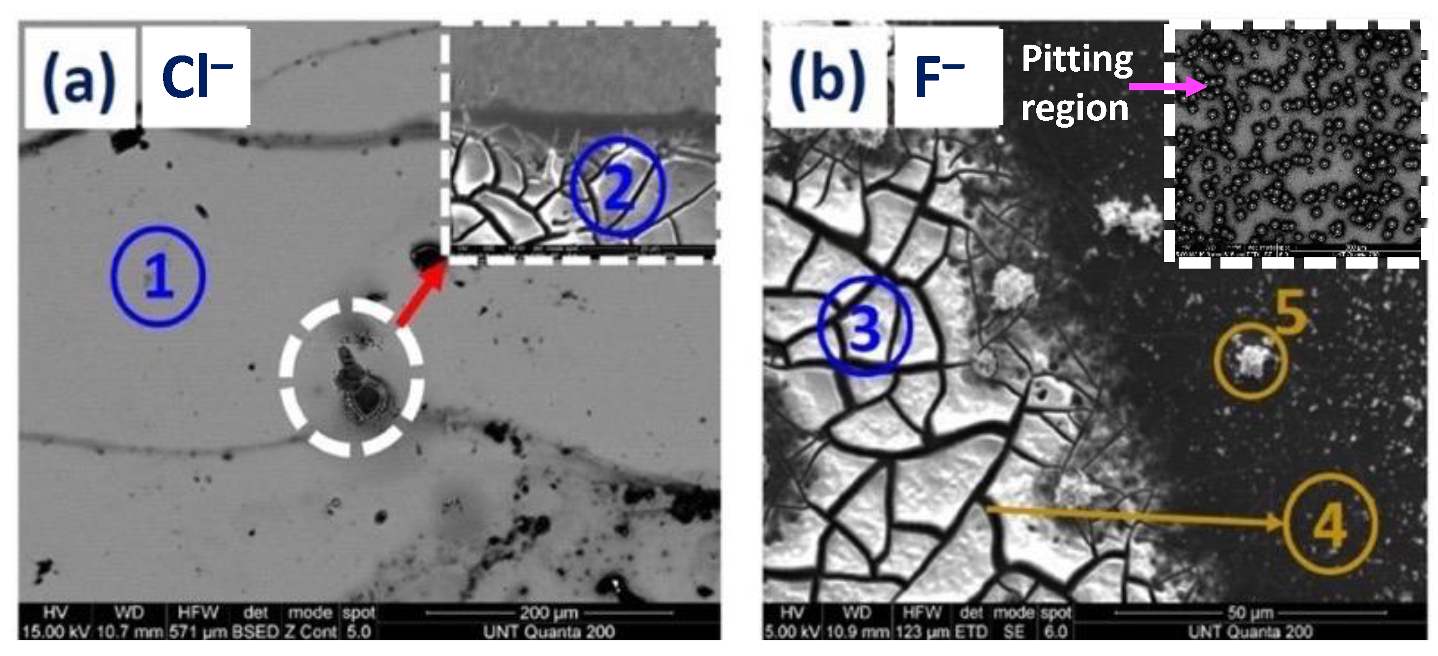
3.1.1. SEM and EDS Investigation of the Corroded Blanket Al Samples

The SEM analyses of the corroded Al samples further corroborated the surface morphology difference after 24 h of corrosion. As shown in Figure 3, the F corrosion was characterized by extensive pitting (Figure 3b inset) all over the Al sample, whereas the Cl sample showed only surface roughening after 24 h with very few pitting spots. SEM imaging of the F-corroded sample on the pitting shows mud crack morphology on the Al surface with additional surface precipitates (Figure 3b). EDX analysis on the mud crack region and surface precipitates revealed an F signal on the sample, indicating the presence of Al-F surface products. The area between the mud crack islands showed minimal Al and O signals due to the extensive Al corrosion that reached the underlying Si substrate.
The Cl sample showed no extensive pitting or widespread mud crack corrosion morphology, indicating a slow uptake of Cl ions by the Al oxide surface. Further zoomed-in inspection of the pitting area revealed mud crack corrosion morphology but on a much smaller scale. EDX analysis on the corroded (surface roughened) area and mud crack region revealed the absence of a Cl signal on the Al substrate, implying Al-Cl surface products’ absence. The presence of surface products in F supports the assertion of having different corrosion attacking mechanisms and different corrosion products in comparison with Cl. The corroded Al EDX characterization and its elemental composition result are shown in Table 1.

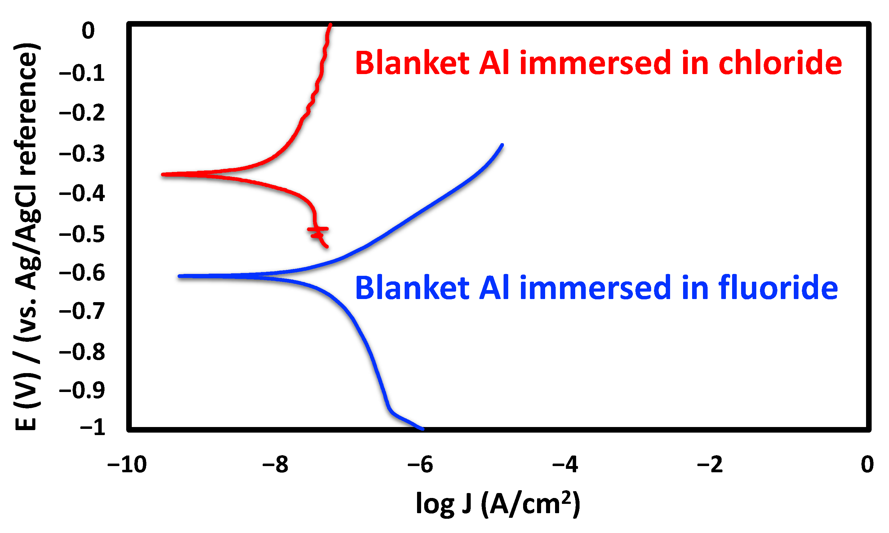
3.1.2. Electrochemical Characterization Studies

The Tafel plot analysis observed a similar corrosion trend as the above-mentioned corrosion screening on the blanket Al. As shown in Figure 4, the corrosion potential of Al in 5 ppm F solution (Ecorr = −0.62 V) was considerably more negative than the corrosion potential in 5 ppm Cl solution (Ecorr = −0.37 V). In addition, the corrosion current density of Al in F solution (Jcorr = 16.9 nA/cm2) was close to 10 times higher than in Cl solution (Jcorr = 1.8 nA/cm2). Therefore, the observed Tafel data supported the assertion that F ions can readily break down the passivation Al2O3 layer to result in significant pitting corrosion on the Al surface (see Figure 2c). In comparison, it is less thermodynamically favorable for Cl ions to break the passive Al2O3 layer, resulting in less corrosion observed on the Al substrate.
Next, the galvanic corrosion currents were measured, as shown in Figure 5, by the galvanic coupling of Cu and Al electrodes while immersed in Cl or F solutions. In this Cu/Al couple, the Cu acted as the cathode and Al as the anode. The Cu/Al galvanic couple immersed in 5 ppm F solution showed the Al corrosion current increasing to near 4 µA in about 20 min. The galvanic couple immersed in F solution for 60 min showed an average galvanic coupling current of ca. 3 µA. Contrastingly, the galvanic couple immersed in 5 ppm Cl solution showed the onset of corrosion only after 5 min. The observed galvanic current was around 0.7 µA, almost four times lesser than the observed current in F solution. The galvanic corrosion current measurement of the Cu/Al couple in F solution displayed the ready breakdown of passivating Al oxide in comparison with Cl solution similar to the observed Al Tafel plot analysis for blanket Al samples.

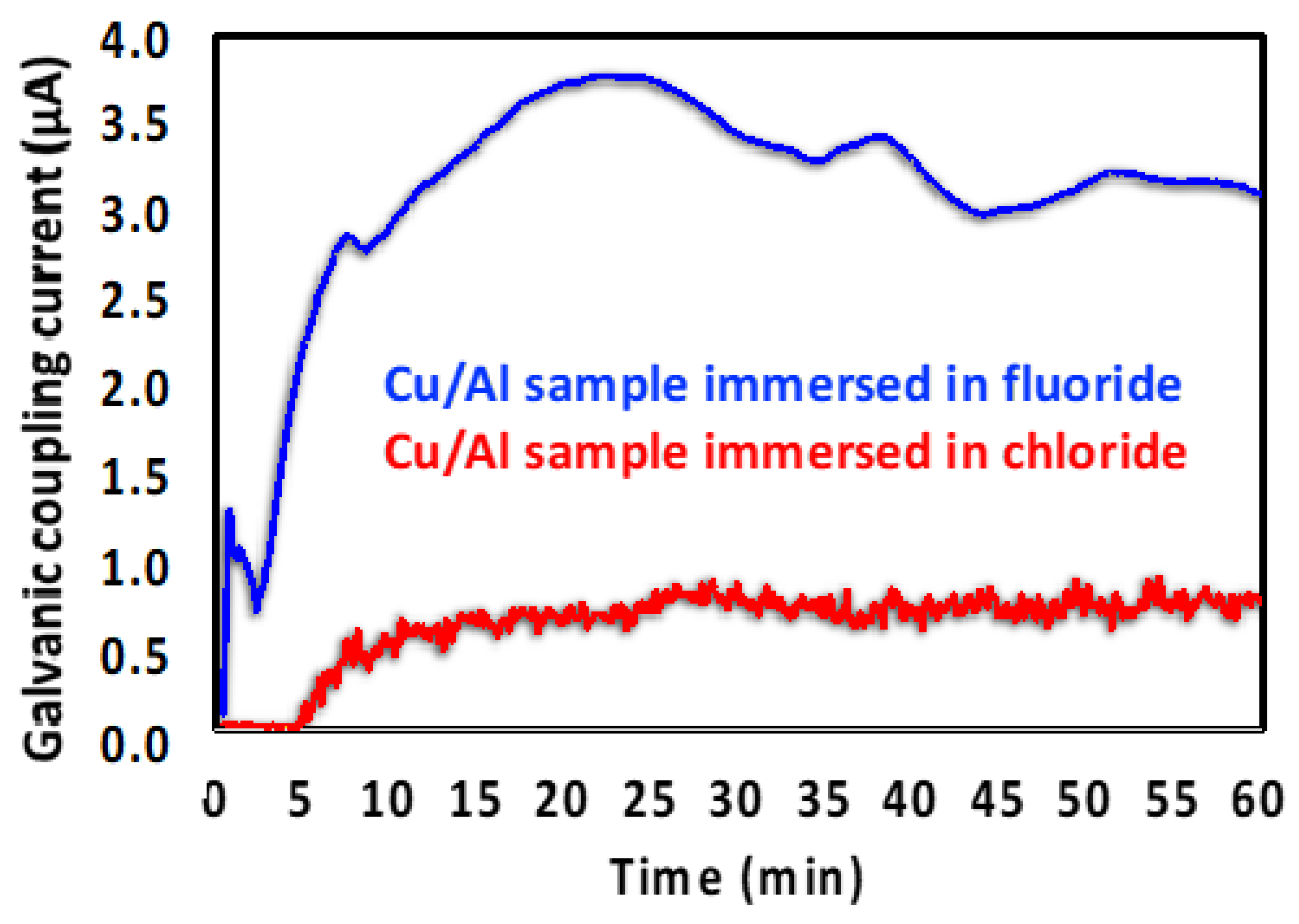
3.2. Halide-Induced Corrosion of Al with Bimetallic Contact to Cu

The Al corrosion under the influence of Cu/Al bimetallic contact was studied using micropattern samples to simulate the real-life Cu wire-bonded device situation. As shown in Figure 1, the standing Cu microdots represent the Cu bonding wires, which cover the Al surface to simulate Al bonding pads. Solutions of 5 ppm Cl and 5 ppm F were used at pH 5 to study Al corrosion in a bimetallic contact situation similar to that shown in Figure 2. As shown in Figure 6, the Al corrosion progression was starkly different with the presence and absence of a peripheral Cu bimetallic contact. In the absence of peripheral Cu bimetal contact (see Figure 2b), in a 5 ppm Cl solution at pH 5, Al showed minor corrosion, and the corrosion rate was much slower. However, the presence of Cu bimetallic contacts made the corrosion of the Al layer more aggressive, accompanied by immediate gas escape at the corrosion site. This gas was later analyzed and confirmed as hydrogen (H2) gas using a GC–MS, shown in the later section of Figure 9. In addition, a dendritic structure was also formed on the corroded Al surface, resulting in cracks on the Al surface, similar to the mud-crack-like surface morphology. The addition of a bimetallic contact (Cu) on the Al surface helped the Cl ions break down the passivation layer on Al more readily, coupled with H2 gas evolution, resulting in increased corrosion activity. As shown in Figure 6d, the Al surface was corroded entirely in only 8 h with bimetallic contact, compared with only minor corrosion observed on the Al blanket sample after 24 h (see Figure 2b).
In the F corrosion study (see Figure 7), compared with Cl, the Al corrosion morphology screened by Cu micropattern corrosion was entirely different. Al corrosion was highly concentrated around the Cu/Al interface in the presence of F ions. Additionally, corrosion was observed in the Al substrate between the Cu dots. A significant contrast was that compared with the Cl corrosion mentioned earlier, no visible gas escape, dendrites, or mud cracks were seen in the F corrosion. Even after 12 h, the corrosion was limited to the Cu/Al interface and Al area. The Al between the Cu dots showed some removal, as evidenced by the fading color change observed in Figure 7b,d with minimal dendrite corrosion and no gas evolution.

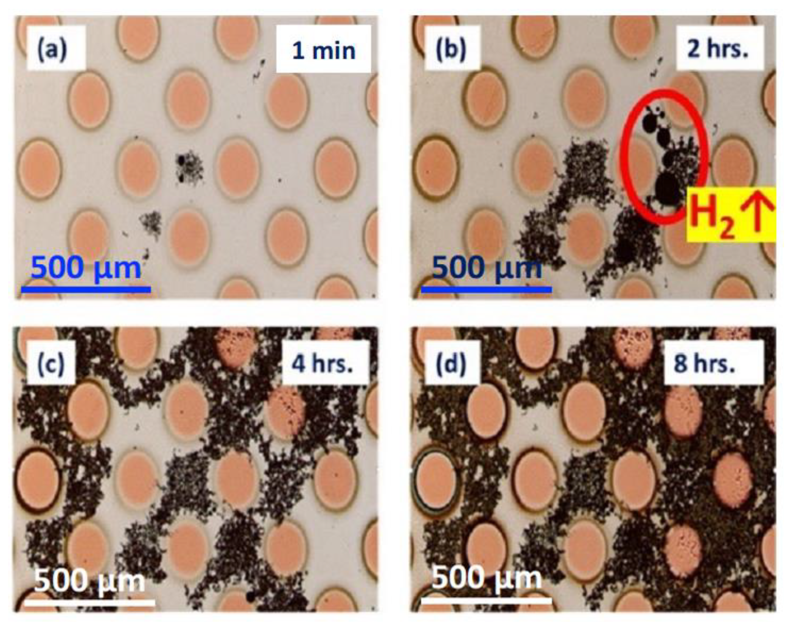
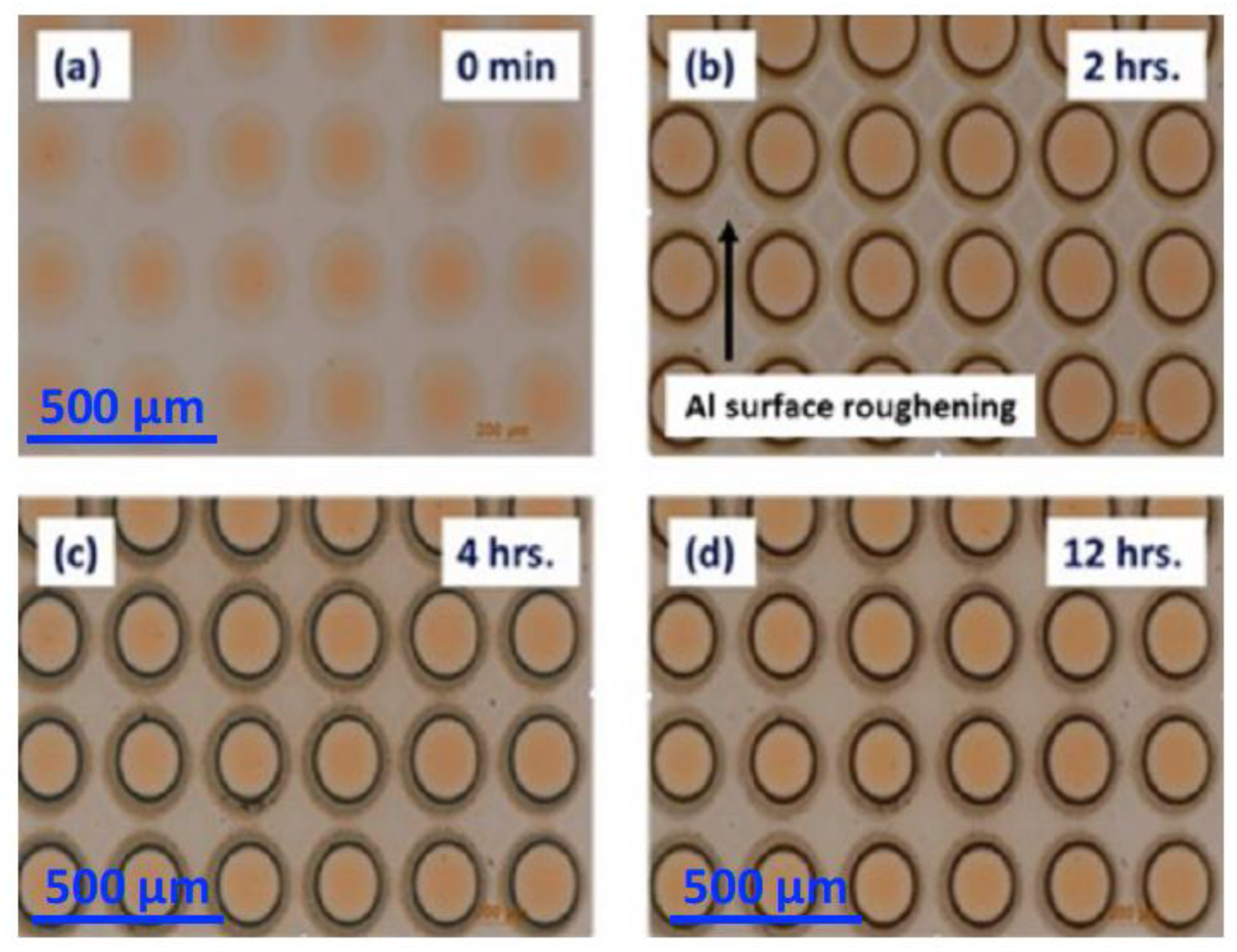
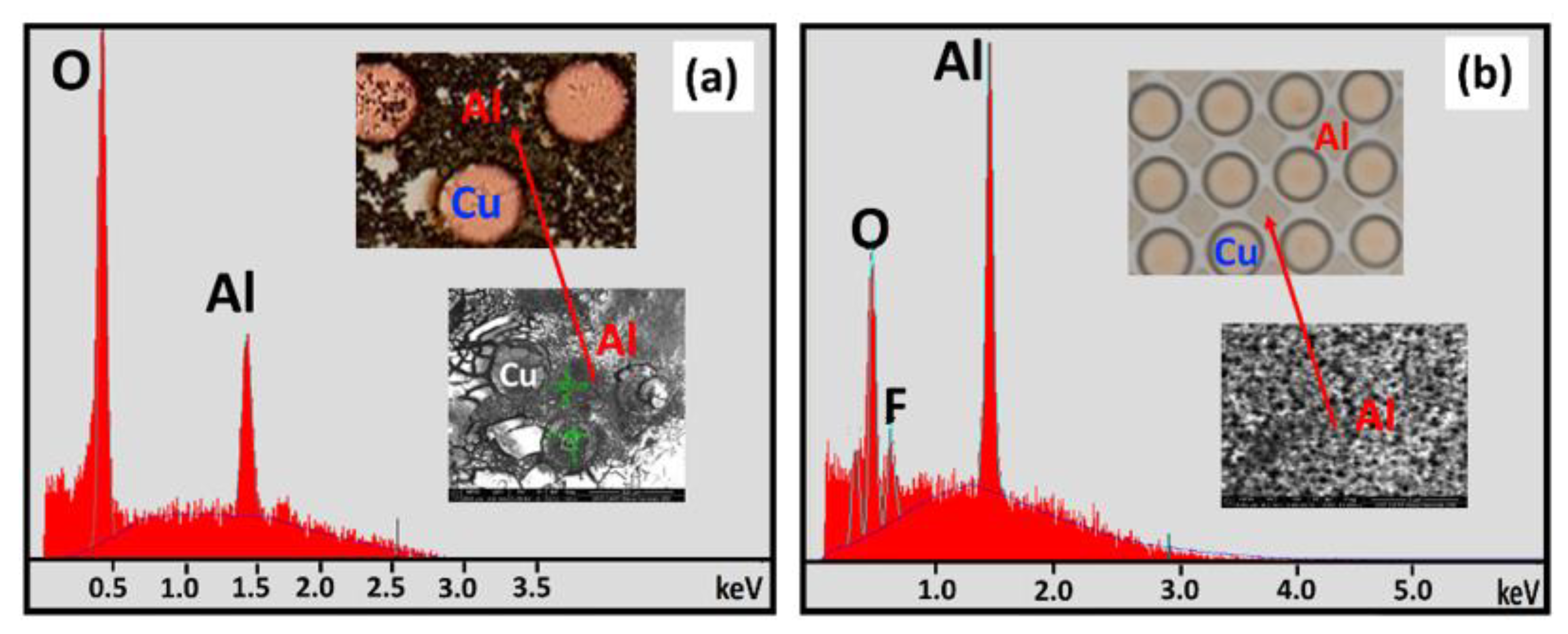
3.2.1. SEM and EDS Investigation of the Corroded Micropattern Cu/Al Samples

After 44 h of immersion in 5 ppm Cl and 5 ppm F, as shown in Figure 8, EDS analyses of the corroded samples revealed the difference in surface products between Cl- and F-immersed corrosion. The EDS spectrum of the severely corroded Al surface (Figure 8a) exposed to 5 ppm Cl showed mostly Al and O signals that suggested dendrite formation, as the corrosion product was mainly Al(OH)3. In addition, the observed H2 gas evolution (Figure 6b) could generate high internal pressure to rupture and delaminate the Al film. This, in turn, caused more freshly exposed non-passivated Al metal to corrode and form more Al(OH)3 dendrites.
In contrast, the EDS spectrum of F-corroded samples, as shown in Figure 8b, revealed an F signal in addition to O and Al signals, indicating that surface products such as AlFx and AlOFx could form on the Al surface. In addition, it was observed that the SEM image of the corroded Al surface became rough without any dendrites, similar to the situation observed in the surface corrosion of the Al substrate.

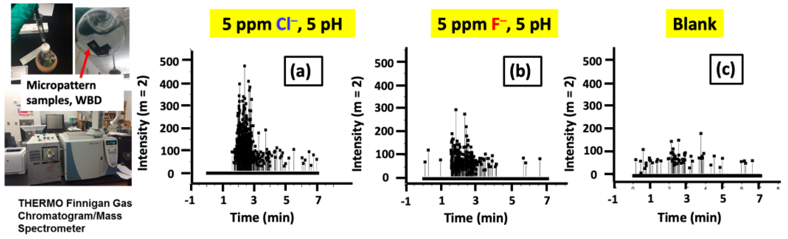
3.2.2. GC–MS Investigation of the Gas Evolution in Microdot Samples

The headspace chromatography analysis of gas evolved showed that under Cu/Al bimetallic contact, Cl contamination gave an extensive signal for H2 (Figure 9a), whereas a minimal H2 signal was observed for the F case (Figure 9b) in comparison with the blank (Figure 9c). The GC–MS data confirmed our hypothesis and corroborated well with what we observed in Cu micropattern corrosion screening (Figure 6 and Figure 7).

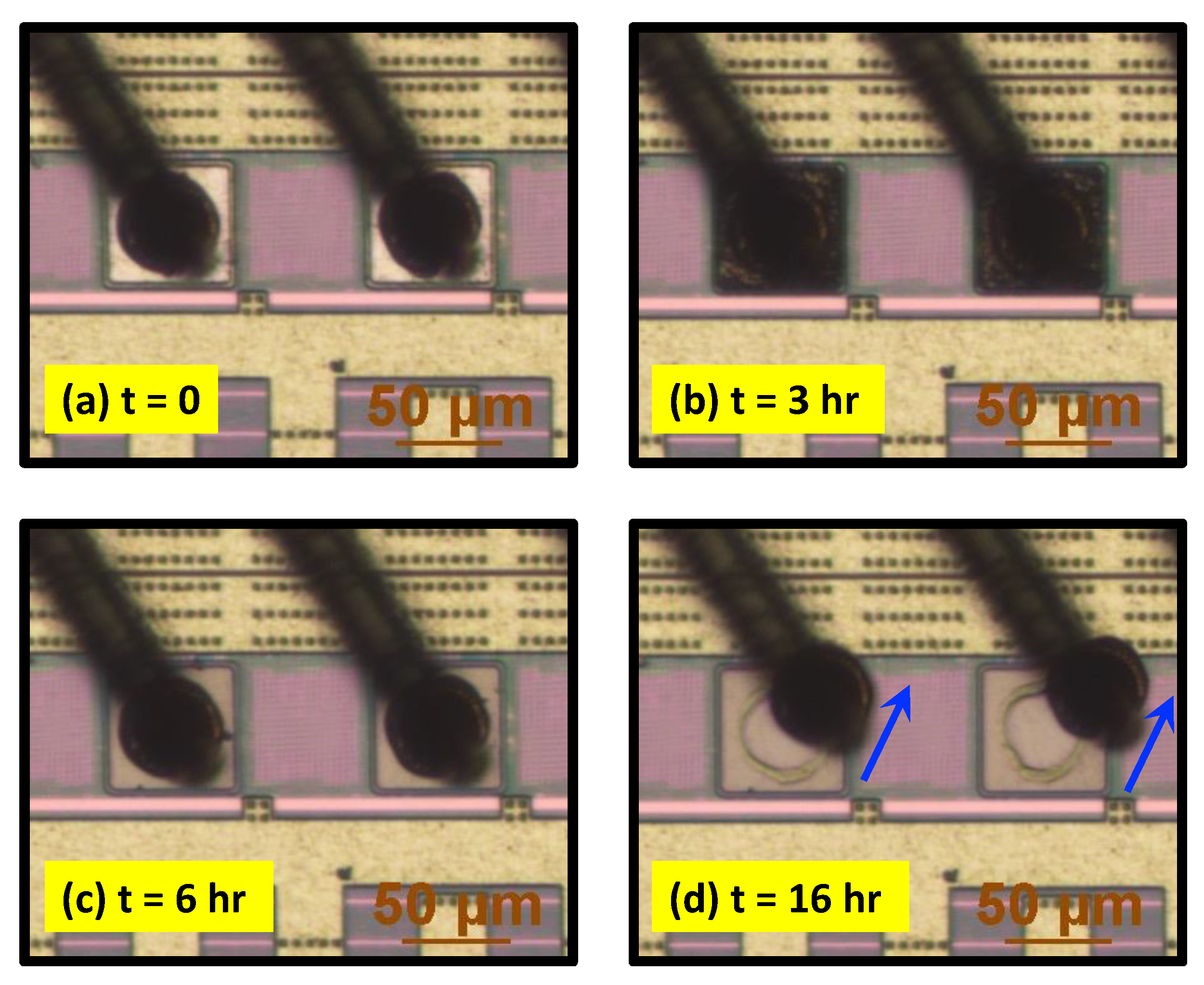
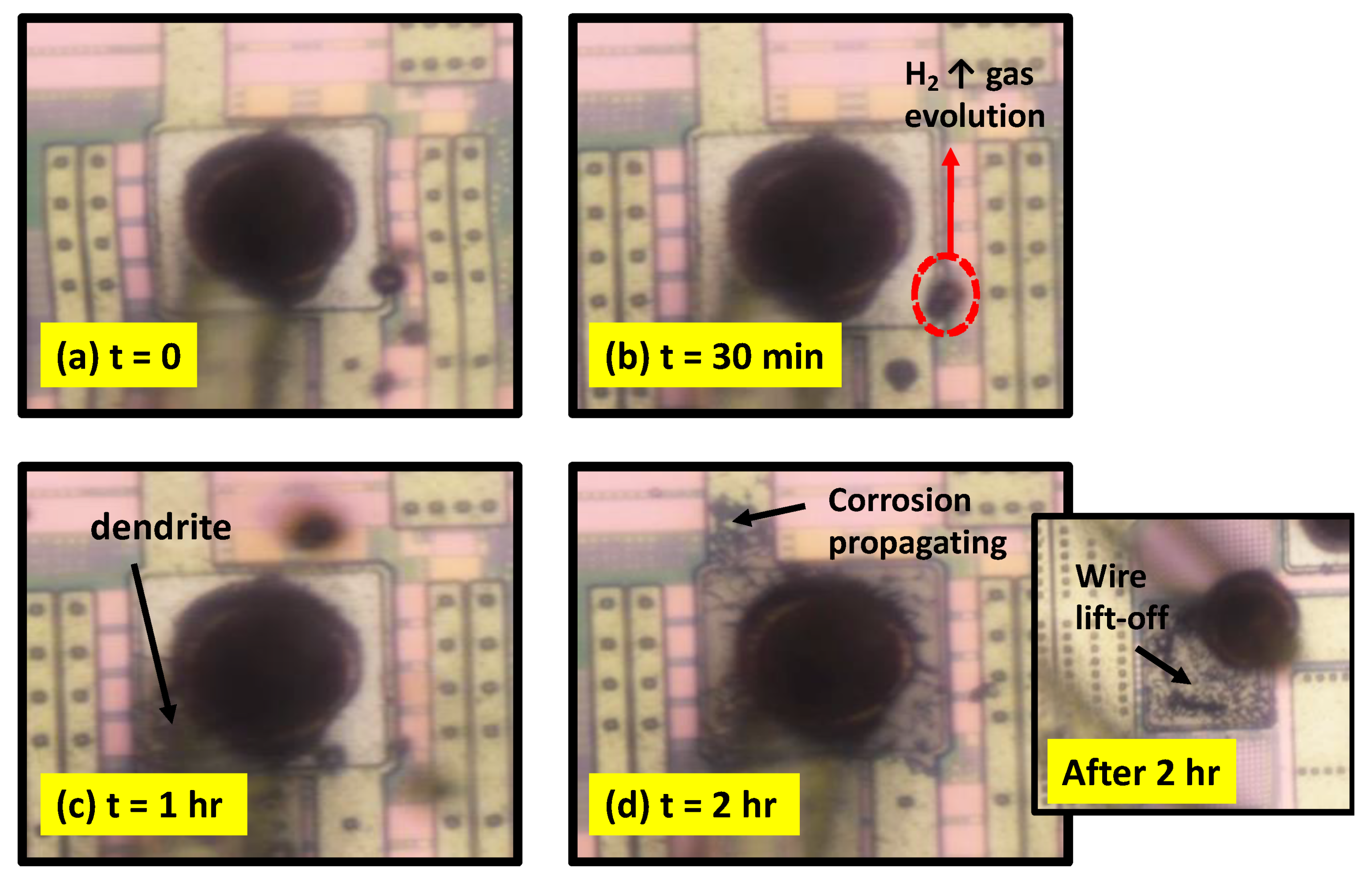
3.3. Halide-Induced Real-Time Corrosion Investigation of WBD

The in situ WBD immersion monitoring of the corrosion morphology in real time matched the corrosion morphology observed in the simulated micropattern immersion screening. The WBD with Cu wire on the Al bonding pad was immersed in a 5 ppm Cl, pH 5 solution. The real-time imaging showed rapid H2 gas escape, accompanied by rapid corrosion propagation with dendrite formation. Al bond pad corrosion extended underneath the Cu ball bond with the progress of time, causing the Cu wire to lift off from the Al pad. The corrosion screening data showed that even such low ppm levels of Cl concentration can result in aggressive Al pad corrosion, Cu bonding ball lift-off, and thus complete device failure in about 2 h, as shown in Figure 10d and inset.
Figure 11 shows the corrosion progress of WBD immersed in 5 ppm F, pH 5 solution, which is very similar to the corrosion of micropatterned samples observed in F. Further in situ investigation showed Al pad complete corrosion visible from its color change, as shown in Figure 11b, in about 3 h. Then the Al pad thin film was corroded entirely, revealing the underneath metallization layer, as shown in Figure 11c. The corrosion was then progressed by F ion contaminants seeping underneath the wire to corrode the pad buried underneath the ball bond, leading to wire lift-off in about 27 h. The wire lift-off in F corrosion was much slower than the Cl corrosion, which can be attributed to the absence of rapid H2 evolution in the F-induced Al corrosion process. The difference in corrosion morphology confirmed in blanket Al, micropattern Cu dot on Al, and WBD between Cl and F establishes that the mechanism of these contaminants is utterly different in their attacking nature towards the Al surface.

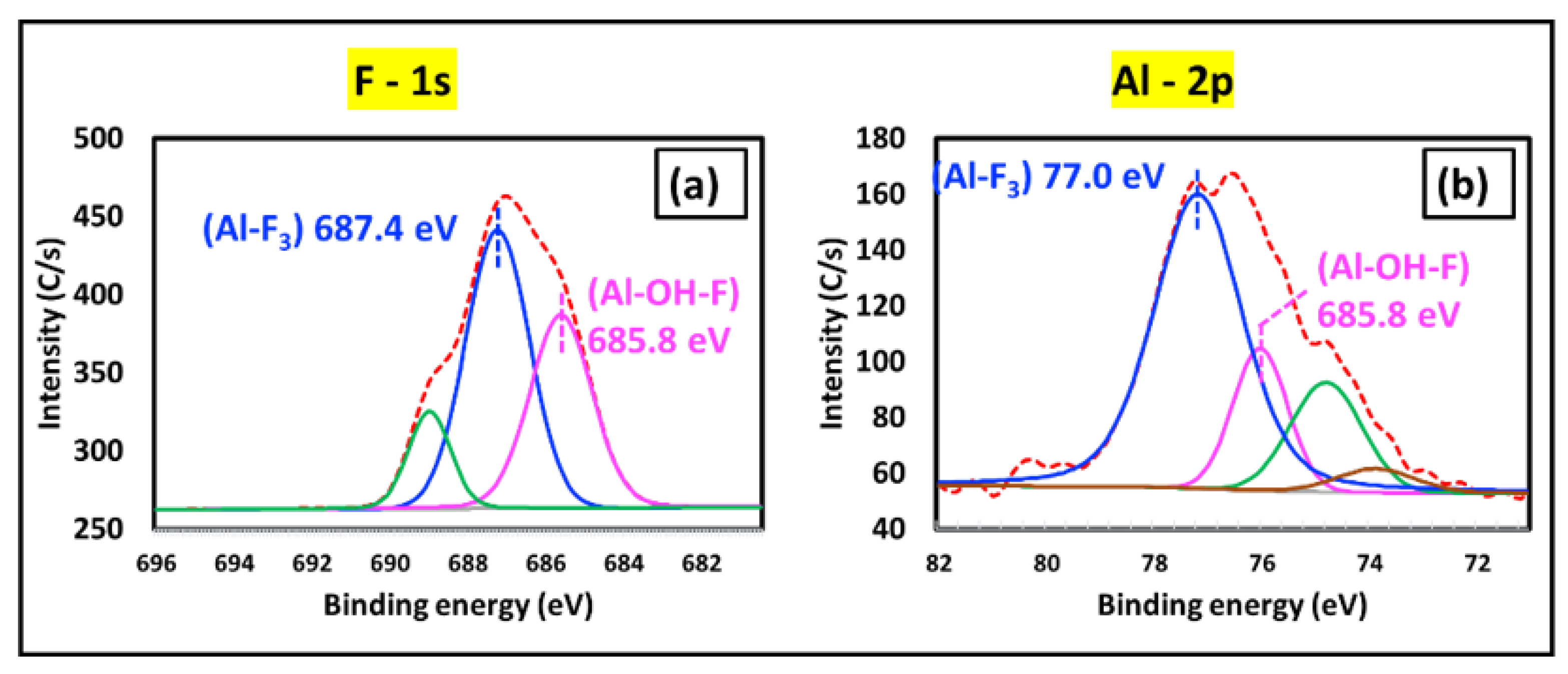
XPS Analysis of the Corroded Al Bond Pad

As shown in Figure 12, XPS analysis of the 3 h corroded WBD (see Figure 10b) with the F surface products on Al was carried out to identify its bonding chemistry. The XPS spectrum in the region of the F-1s signal on the corroded black region was deconvoluted due to the presence of a shoulder, which showed the central peak at 687.4 eV corresponding to AlF3 species present on the surface and the secondary peak at 685.8 eV related to the presence of aluminum oxyfluoride species (Figure 12a) [19]. The Al 2p spectrum investigation revealed a prominent peak of 77.0 eV after the deconvolution, confirming AlF3 surface products as the main species during corrosion along with some Al-hydroxy-F species seen from the secondary peak observed at 75.8 eV, as shown in Figure 12b [20]. The additional green spectra observed with a peak at 689 eV and 74.6 eV corresponded to the organic fluorides, and the brown spectra observed with a peak at 73.8 eV corresponded to Al-O species on the corroded surface [21].

4. Discussion

Corrosion Mechanism Comparison of Cl vs. F

Visual investigation of the corroded blanket Al surface showed more vigorous pitting and mud crack corrosion in F solution than in Cl solution, which only showed mild pitting and surface roughening. The stark difference in this extent of attack between Cl and F, as shown in Figure 2, can come from two main reasons. First, F, being a stronger base than Cl, can attack the positively surface-charged oxide layer in solution more readily due to a stronger acid–base interaction. Second, Al surface oxide is well known to form a series of complexes with F ions ranging from AlF2+ to AlF63− [22] and reported literature shows that the adsorption of F by Al oxide is maximum at pH 5 [23]. The EDS analyses of the corroded Al surface revealed a key difference in corrosion products (see Table 1). The mud crack islands seen in Cl samples did not have any measurable Cl signal, whereas a strong signal for F was observed on Al samples corroded in F solutions. In the case of Cl, we propose that Al corrodes to give AlCl3 as the primary corrosion product. The high solubility of AlCl3 (460 g/L @ 30 °C) in aqueous solutions [24] results in the formation of Al(OH)3 via hydrolysis. The EDS of mud cracks from Cl corrosion agrees well with this statement as it only has Al and O signals, and no Cl signal was observed. However, that is not the case with F corrosion. The primary corrosion product proposed in this case would be aluminum trifluoride (AlF3), a relatively poorly soluble compound (0.0053 g/L @ 20 °C) in aqueous solution [25]. Due to this fact, an intense F signal was seen in the EDS analysis, suggesting the presence of insoluble Al-F species formed due to corrosion. In addition to this insoluble Al-F species, some other more soluble species, such as Al-(OH)-F species, could be forming on the Al samples’ surface [26]. Therefore, in the absence of Cu/Al bimetallic contact, SEM and EDS showed that F contaminant produced more aggressive pitting corrosion than Cl.
Separated in the galvanic series, Cu and Al had almost +2.0 V difference in their standard reduction potential [27]. Cu on bimetallic contact with Al in the presence of Cl showed a different and faster corrosion progression morphology on Al, as shown in Figure 6 compared with Figure 2b. In the Cl condition, this aggressive corrosion was due to the potential difference that thermodynamically accelerated the Al oxidative dissolution by Cl ions, leading to the formation of AlCl3. The hydrolysis of this more soluble AlCl3 product created local acidity (as protons) on the Al surface (Equation (3)). The Cu surface, acting as the cathode in this galvanic couple, functioned as a suitable site for reducing protons to produce H2 evolution (Equation (4)) and was experimentally observed in Figure 6b or Figure 10b. Hydrogen evolution was previously reported as a possible cathodic reaction in a Cu/Al galvanic system [28]. This H2 evolution with rapid volume expansion can create aggressive erosion effects on the Al substrate to form deep corrosion cracks, pits, and dendrites [29]. The detailed mechanism of this Cl corrosion on Cu/Al peripheral bimetallic contact in WBD was previously reported by Ross et al. [16].
Al   Al 3 +   + 3 e
Al 3 + + 3 Cl AlCl 3
AlCl 3   + 3 H 2 O Al ( OH ) 3 + 3 H + + 3 Cl
3 H + + 3 e 3 2 H 2
In the F case, the corrosion morphology observed in Cu/Al bimetallic contact samples, as shown in Figure 7 and Figure 11, was similar to the corrosion in blanket Al (Figure 2c). As observed in Figure 11, no dendrite or H2 evolution was visibly observed; instead, Al dissolution was observed by forming significant surface product AlF3, as confirmed by XPS, as shown in Figure 12. The AlF3 product was slowly removed from the surface, revealing the underneath layer observed in Figure 12b. The mechanism of F corrosion was similar with and without the presence of bimetallic contact mainly due to this formation of this poorly soluble AlF3 corrosion product that cannot be easily hydrolyzed and removed like AlCl3. Therefore, the creation of the local high acidity became difficult, as proposed in Equation (3), and hence, the cathodic reaction of H2 evolution was greatly reduced in the F condition.
In summary, the Cl-induced corrosion in WBD is a highly efficient electrochemical corrosion process, driven by Cu/Al bimetallic contact, with rapid removal of the corroded product, Al(OH)3 dendrites, and reduction product of the active H2 evolution. In contrast, the F corrosion process has a rate-determined step of slower dissolution reaction of Al to AlF3, as confirmed by XPS analysis on WBD (Figure 12a). Consequently, the smaller amount of H2 gas observed in GC–MS (Figure 9b) and the less soluble nature of intermediates, such as Al(OH)x(F)y, as suggested by the XPS analysis (Figure 12), further slowdown the overall F-induced corrosion on Al pads of Cu WBD.
For Cl corrosion, the potential prevention strategy proposed is to halt the H2 evolution (cathodic reaction) by using an azole-based Cu-selective inhibitor to eliminate the galvanic contact, thereby preventing the redox corrosion process. A copper (cathode)-specific azole inhibitor was applied to the Cu wire, and the device was subjected to the same Cl corrosion condition. Figure 13a shows that the Cu selective inhibitor completely prevented H2 gas evolution and inhibited corrosion dendrite formation on the Al bond pads. Contrastingly, F, as a stronger etchant to the Al pad, leading to the formation of a less soluble AlF3, received no protection from the same Cu-selective inhibitor, as shown in Figure 13b. This mechanistic investigation gave us key insight in identifying the difference in mechanism between the two halide contaminants and highlighted the need for further development of Al-specific inhibitors to protect WBDs from F corrosion.

5. Conclusions

The corrosion morphology and mechanism of Al corrosion in Cl and F were compared in the 5 ppm level contaminations at pH 5. Al was found to corrode very differently with and without bimetallic contact. The nature and solubility of the proposed corrosion product (AlCl3 vs. AlF3) were found to influence the corrosion morphology, corrosion products, and sustaining corrosion progression. In addition, H2 evolution was observed extensively only in Cl-induced Al corrosion aided by bimetallic contact. The obtained mechanistic insights using Cu micropattern corrosion screening could be beneficial in exploring the Al bond pad corrosion in Cu wire-bonded devices. Research is ongoing to test Al corrosion prevention mechanisms in real-life Cu wire-bonded devices to formulate preventive measures further to mitigate halide-induced corrosion. While stopping the electrochemical reaction can solve the corrosion of Al in a Cl environment under Cu/Al bimetallic influence, the same would not help in preventing corrosion caused by F ions as it is much more of a dissolution reaction and proceeds similarly in the presence and absence of Cu/Al bimetallic contact.

Author Contributions

Methodology, data curation, investigation, writing—original draft preparation, G.I.A.K.; data curation, investigation, visualization, A.L.; data curation, investigation, writing—review and editing, software, J.C.; investigation, visualization, writing—review, and editing, M.A.; investigation, W.Y.; conceptualization, supervision, project administration, funding acquisition, resources, O.C. All authors have read and agreed to the published version of the manuscript.

Funding

The authors gratefully acknowledge the financial supports from SRC (GRC 2665.001) and the University of North Texas for this study.

Institutional Review Board Statement

Not applicable.

Informed Consent Statement

Not applicable.

Data Availability Statement

The data presented in this study are available on request from the corresponding author. The data are not publicly available due to usage of WBD obtained from industrial collaborators, which can reveal their design patterns.

Acknowledgments

O.C. would like to thank Varughese Mathew for the helpful discussion and assistance. O.C. also acknowledges the UNT Materials Research Facility (MRF) for providing SEM/EDS characterization assistance. The authors acknowledge the UNT Chemistry Departmental Instrumentation Laboratory and Jose Calderon for the assistance in GC–MS.

Conflicts of Interest

The authors declare that they have no known competing financial interests or personal relationships that could have appeared to influence the work reported in this paper.

References

  1. Gan, C.L.; Hashim, U. Evolutions of bonding wires used in semiconductor electronics: Perspective over 25 years. J. Mater. Sci. Mater. Electron. 2015, 26, 4412–4424. [Google Scholar] [CrossRef]
  2. Liu, D.; Chen, H.; Wu, J.; Then, E. Corrosion Behavior of Cu-Al Intermetallic Compounds in Copper Wire Bonding in Chloride-Containing Accelerated Humidity Testing. In Proceedings of the 2016 IEEE 66th Electronic Components and Technology Conference (ECTC), Las Vegas, NV, USA, 31 May–3 June 2016; pp. 629–636. [Google Scholar] [CrossRef]
  3. Fu, S.-W.; Lee, C.C. A corrosion study of Ag–Al intermetallic compounds in chlorine-containing epoxy molding compounds. J. Mater. Sci. Mater. Electron. 2017, 28, 15739–15747. [Google Scholar] [CrossRef] [Green Version]
  4. Yang, Y.; Zhu, X.; Nistala, R.R.; Zhao, S.; Xu, J. A method to simulate fluorine outgas and Al bond pad corrosion in wafer fab. In Proceedings of the 2016 IEEE 23rd International Symposium on the Physical and Failure Analysis of Integrated Circuits (IPFA), Singapore, 18–21 July 2016; pp. 340–343. [Google Scholar] [CrossRef]
  5. Younan, H.; Xiang, X.Z.; Xiaomin, L. Characterization studies of fluorine-induced corrosion crystal defects on microchip Al bondpads using X-ray photoelectron spectroscopy. In Proceedings of the 2014 IEEE 21th International Symposium on the Physical and Failure Analysis of Integrated Circuits (IPFA), Singapore, 30 June–4 July 2014; pp. 90–93. [Google Scholar] [CrossRef]
  6. Song, M.; Mathew, V.; Li, L.; Wang, S.; Han, M.C.; Song, Y.; Descartin, A.M. A New Finding of Cu-Al IMC Corrosion and Investigation of Fluorine Contamination Influence on Cu-Al IMC Corrosion. In Proceedings of the 20th International Conference on Electronic Packaging Technology (ICEPT), Hong Kong, China, 11–15 August 2019; pp. 1–4. [Google Scholar] [CrossRef]
  7. Farrah, H.; Slavek, J.; Pickering, W. Fluoride interactions with hydrous aluminum oxides and alumina. Soil Res. 1987, 25, 55–69. [Google Scholar] [CrossRef]
  8. Proost, J.; Baklanov, M.; Verbeeck, R.; Maex, K. Morphology of corrosion pits in aluminum thin film metallizations. J. Solid State Electrochem. 1998, 2, 150–155. [Google Scholar] [CrossRef]
  9. Loto, R.T. Investigation of the Localized Corrosion Resistance of 4044 Aluminum Alloy in Acid Chloride and Neutral Chloride Solutions. J. Fail. Anal. Prev. 2018, 18, 905–911. [Google Scholar] [CrossRef]
  10. Lall, P.; Luo, Y.; Nguyen, L. Chlorine-Ion Related Corrosion in Cu-Al Wirebond Microelectronic Packages. In International Electronic Packaging Technical Conference and Exhibition; American Society of Mechanical Engineers: New York, NY, USA, 2015; p. V002T02A012. [Google Scholar] [CrossRef]
  11. Mathew, V.; Wikramanayake, E.; Chopin, S.F. Corrosion of Copper Wire bonded Packages by Chlorine Containing Foreign Particles. In Proceedings of the 2020 IEEE 70th Electronic Components and Technology Conference (ECTC), Lake Buena Vista, FL, USA; 2020; pp. 504–511. [Google Scholar] [CrossRef]
  12. Liao, L.J.; Zhang, X.; Li, X.; Hua, Y.; Fu, C.; Tee, W.; Yee, B.; Wang, B.; Mao, S. Comprehensive study of wire bond reliability impacts from wire, molding compound and bond pad contamination. In Proceedings of the 17th IEEE International Conference on IC Design and Technology (ICICDT), Suzhou, China, 17–19 June 2019. [Google Scholar] [CrossRef]
  13. Uno, T. Bond reliability under humid environment for coated copper wire and bare copper wire. Microelectron. Reliab. 2011, 51, 148–156. [Google Scholar] [CrossRef]
  14. Chauhan, P.; Zhong, Z.W.; Pecht, M. Copper Wire Bonding Concerns and Best Practices. J. Electron. Mater. 2013, 42, 2415–2434. [Google Scholar] [CrossRef]
  15. Zeng, Y.; Bai, K.; Jin, H. Thermodynamic study on the corrosion mechanism of copper wire bonding. Microelectron. Reliab. 2013, 53, 985–1001. [Google Scholar] [CrossRef]
  16. Ross, N.; Asokan, M.; Kumar, G.I.A.; Caperton, J.; Alptekin, J.; Salunke, A.S.; Chyan, O.M. Mechanistic study of copper wire-bonding failures on packaging devices in acidic chloride environments. Microelectron. Reliab. 2020, 113, 113917. [Google Scholar] [CrossRef]
  17. Kumar, G.I.A.; Alptekin, J.; Caperton, J.; Salunke, A.; Chyan, O. Accelerated reliability testing of Cu-Al bimetallic contact by a micropattern corrosion testing platform for wire bond device application. MethodsX 2021, 8, 101320. [Google Scholar] [CrossRef]
  18. Semiconductor Epoxy Mold Compounds. Available online: https://www.caplinq.com/semiconductor-epoxy-mold-compounds.html (accessed on 10 June 2021).
  19. Moreno-López, J.C.; Ruano, G.; Ferrón, J.; Ayala, P.; Passeggi, M.C.G. Thermally Annealed Sub-Monolayers of AlF 3 on Cu(100): An STM and XPS Study. Phys. Status Solidi B 2018, 255, 1800389. [Google Scholar] [CrossRef] [Green Version]
  20. Chastain, J.; Moulder, J.F. Handbook of X-ray Photoelectron Spectroscopy: A Reference Book of Standard Spectra for Identification and Interpretation of Xps Data; Physical Electronics Inc.: Eden Prairie, MN, USA, 1995; pp. 230–232. ISBN 0-9648124-1-X. [Google Scholar]
  21. Roodenko, K.; Halls, M.; Gogte, Y.; Seitz, O.; Veyan, J.-F.; Chabal, Y.J. Nature of Hydrophilic Aluminum Fluoride and Oxyaluminum Fluoride Surfaces Resulting from XeF2 Treatment of Al and Al2O3. J. Phys. Chem. C 2011, 115, 21351–21357. [Google Scholar] [CrossRef]
  22. Xue, T.; Cooper, W.C.; Pascual, R.; Saimoto, S. Effect of fluoride ions on the corrosion of aluminium in sulphuric acid and zinc electrolyte. J. Appl. Electrochem. 1991, 21, 238–246. [Google Scholar] [CrossRef]
  23. Tang, Y.; Guan, X.; Su, T.; Gao, N.; Wang, J. Fluoride adsorption onto activated alumina: Modeling the effects of pH and some competing ions. Colloids Surf. A Physicochem. Eng. Asp. 2009, 337, 33–38. [Google Scholar] [CrossRef]
  24. Seidell, A. Solubilities of Inorganic and Organic Compounds, 2nd ed.; D Van Nostrand Company: New York, NY, USA, 1919; p. 25. [Google Scholar]
  25. Millipore Sigma. Safety Data Sheet. Available online: https://www.sigmaaldrich.com/US/en/sds/SIGMA/A8205 (accessed on 16 June 2021).
  26. Cowley, J.M.; Scott, T.R. Basic Fluorides of Aluminum. J. Am. Chem. Soc. 1948, 70, 105–109. [Google Scholar] [CrossRef]
  27. Atkins, P.; Paula, J. Chemical Equilibrium: Electrochemistry. In Elements of Physical Chemistry, 5th ed.; Oxford University Press: New York, NY, USA, 2009; Chapter 9; p. 212. [Google Scholar]
  28. Curioni, M.; Scenini, F. The Mechanism of Hydrogen Evolution During Anodic Polarization of Aluminium. Electrochim. Acta 2015, 180, 712–721. [Google Scholar] [CrossRef]
  29. Vrublevsky, I.; Parkoun, V.; Sokol, V.; Schreckenbach, J.; Marx, G. The study of the volume expansion of aluminum during porous oxide formation at galvanostatic regime. Appl. Surf. Sci. 2004, 222, 215–225. [Google Scholar] [CrossRef]
Figure 1. (a) Schematic representation of the immersion micropattern corrosion screening metrology and (b) micropattern sample peripheral bimetallic contact created to simulate the effect of Cu wire on the Al bond pad.
Cmd 02 00023 g001
Figure 2. Corrosion screening of blanket Al samples. (a) As prepared before immersion. (b) Immersed in 5 ppm Cl at pH 5 for 24 h. (c) Immersed in 5 ppm F at pH 5 for 24 h.
Cmd 02 00023 g002
Figure 3. SEM analysis of corroded Al surface. (a) Al surface after 24 h immersion in 5 ppm Cl at pH 5. Inset (white dotted line): Close-in view of mud crack in Cl-induced corrosion. (b) Al surface after 24 h immersion in 5 ppm F at pH 5—close-in view of mud cracks formed in F-induced corrosion. Inset (white dotted line): Close-in view of the pitting region. Note: EDX analyzed the numbered cycle areas; results are listed in Table 1.
Cmd 02 00023 g003
Figure 4. Tafel plot analysis of Al without bimetallic contact in Cl and F containing solutions (5 ppm, pH 5). The scan rate used is 0.001 V/s.
Cmd 02 00023 g004
Figure 5. Galvanic coupling current for Cu-Al couple immersed in 5 ppm Cl and 5 ppm F solutions at pH 5.
Cmd 02 00023 g005
Figure 6. Micropattern corrosion screening of Al/Cu bimetallic contact immersed in 5 ppm Cl solution at pH 5. The images were taken (a) soon after immersion (b); immersion time = 2 h, (c) 4 h, (d) 8 h.
Cmd 02 00023 g006
Figure 7. Micropattern corrosion screening of Al/Cu bimetallic contact immersed in 5 ppm F solution at pH 5. The images were taken at (a) 0 h after immersion; (b) immersion time = 2 h, (c) 4 h, (d) 12 h.
Cmd 02 00023 g007
Figure 8. EDS analysis spectrum of corroded Cu microdot samples on Al after 44 h of immersion in (a) 5 ppm Cl, pH 5, and (b) 5 ppm F, pH 5 (inset: SEM and microscope image of the corroded samples).
Cmd 02 00023 g008
Figure 9. GC–MS analysis of H2 evolution in microdot samples immersed for 40 h in 5 ppm, pH 5 solutions showing (a) intense gas evolution signal in Cl solution, (b) minimal gas evolution signal in F solution, (c) blank signal without any gas evolution.
Cmd 02 00023 g009
Figure 10. Real-time corrosion progression of WBD (Cu wire on Al bond pad) in 5 ppm Cl, pH 5 solution (a) immediately after immersion, (b) H2 evolution from Cu/Al interface, (c) dendrite initiation and propagation, and (d) complete corrosion of Al pad, resulting in Cu wire lift-off (wire lift-off microscope image, inset).
Cmd 02 00023 g010
Figure 11. Real-time corrosion progression of WBD (Cu wire on Al bond pad) in 5 ppm F, pH 5 solution (a) immediately after immersion; (b) Al pad completely corroded in about 3 h; (c) Al pad completely removed, revealing the underneath layer; and (d) Cu bonding ball lift-off, revealing no Al left on the bonded region.
Cmd 02 00023 g011
Figure 12. (a) F-1s core level and (b) Al 2p core level X-ray photoelectron spectra of the corroded Al pad immersed in 5 ppm F, pH 5 solution after 3 h (red dotted lines reveal the original spectra before deconvolution).
Cmd 02 00023 g012
Figure 13. Copper-specific inhibitor coated to WBD immersed in (a) 5 ppm Cl, pH 5 solution for more than 24 h showing Al pad protection and no Cu wire lift-off (inset: zoomed-in image of Al bond pad region remaining protected) and (b) 5 ppm F, pH 5 solution for more than 24 h showing complete corrosion of Al bond pad (inset: zoomed-in image of Al bond pad region corroded).
Cmd 02 00023 g013
Table 1. EDS data for spots numbered in the SEM images in Figure 3.
Figure NumberEDX Spot NumberArea DescriptionAl Atomic %O Atomic %Cl Atomic %F Atomic %Si Atomic %
5a.1Al surface94.95.0------0.0
5a.2Cl—mud crack island45.848.9------0.0
5b.5F—surface precipitate36.557.0---6.50.0
5b.3F—mud crack island38.046.5---15.50.0
5b.4F—crack region between two islands13.717.4---0.567.4
Publisher’s Note: MDPI stays neutral with regard to jurisdictional claims in published maps and institutional affiliations.

