1. Introduction
M50 steel is a high-alloy material, widely used in high-speed and high-temperature bearing applications due to its excellent mechanical properties at elevated temperatures and remarkable wear resistance [
1]. It is extensively applied in aerospace and other high-precision industries [
2]. With increasing demands for high performance, long service life, and reliability of aircraft, bearings often operate under extreme conditions, such as high temperatures, pressures, and rotational speeds. Their lifespan and reliability directly affect aircraft operational safety.
Various methods have been developed to enhance the tribological properties of M50 steel, including surface coating [
3], heat treatment [
4], and surface texturing [
5]. Among these, surface texturing has gained significant attention due to its remarkable friction-reducing and lubrication-enhancing effects [
6]. This technique involves generating micro/nanostructures on the material surface to improve lubrication and wear resistance, enhancing the overall tribological performance. The geometric parameters of the textures are critical for optimizing surface properties [
7,
8].
Qiu et al. [
9] fabricated circular and elliptical textures on stainless steel and found that textured specimens exhibited significantly lower friction coefficients than nontextured counterparts. Lu et al. [
10] produced pit-, groove-, and grid-like textures on chromium surfaces and determined that grid-like textures endowed the best wear resistance to the surfaces. They attributed this improvement to increased surface hardness resulting from laser quenching. Long et al. [
11] compared pit-shaped microtextures and smooth surfaces under starved lubrication conditions, noting that the microtextures exhibited excellent antiwear performance. Zhang et al. [
12] prepared square and radial array textures on Babbitt alloy and concluded that square textures with an area density of ~9% yielded the lowest friction coefficient. To further improve material tribological performance, researchers have developed composite textures. For example, Segu et al. [
13] designed three types of multilayer composite textures on steel surfaces and demonstrated that the textures effectively enhanced friction and wear performance under dry and oil-lubrication conditions. While these studies underscore the importance of rational texture design, current research exhibits notable limitations. Investigations have predominantly focused on textures with a single geometric shape or under specific lubrication conditions, with parameters such as texture shape, size, depth, and area density receiving primary attention [
14].
While the benefits of surface texturing are well-established, a systematic comparative study on the performance of linear versus staggered arrangements of composite shapes under both dry and oil-lubricated conditions is notably lacking for M50 bearing steel. For M50 steel substrates, there remains a significant knowledge gap regarding the synergistic effects of combining different texture geometries and their arrangement patterns (linear versus staggered) on the tribological performance under both dry and oil-lubricated conditions. The underlying mechanisms governing these interactions are not yet fully understood. Therefore, this study fabricated square- and wave-shaped textures in both linear and staggered arrangements on M50 steel substrates and conducted comprehensive friction and wear experiments under dry and oil-lubrication conditions. The research aims to systematically elucidate how texture geometry and arrangement collectively influence tribological performance, thereby providing theoretical insights and practical technical support for enhancing the service life of M50 steel components.
2. Materials and Methods
2.1. Materials and Laser Texturing Preparation
The material used in this study was commercial annealed M50 steel bar, which conforms to AISI M50 or YB4105 standard. The samples, with dimensions of 30 mm × 20 mm × 10 mm, were cut from the same batch of bar stock. The specific chemical composition is shown in
Table 1. The surface was ground and polished to achieve an arithmetic mean roughness (
Ra) of 0.1 μm, measured with a cut-off length of 0.8 mm.
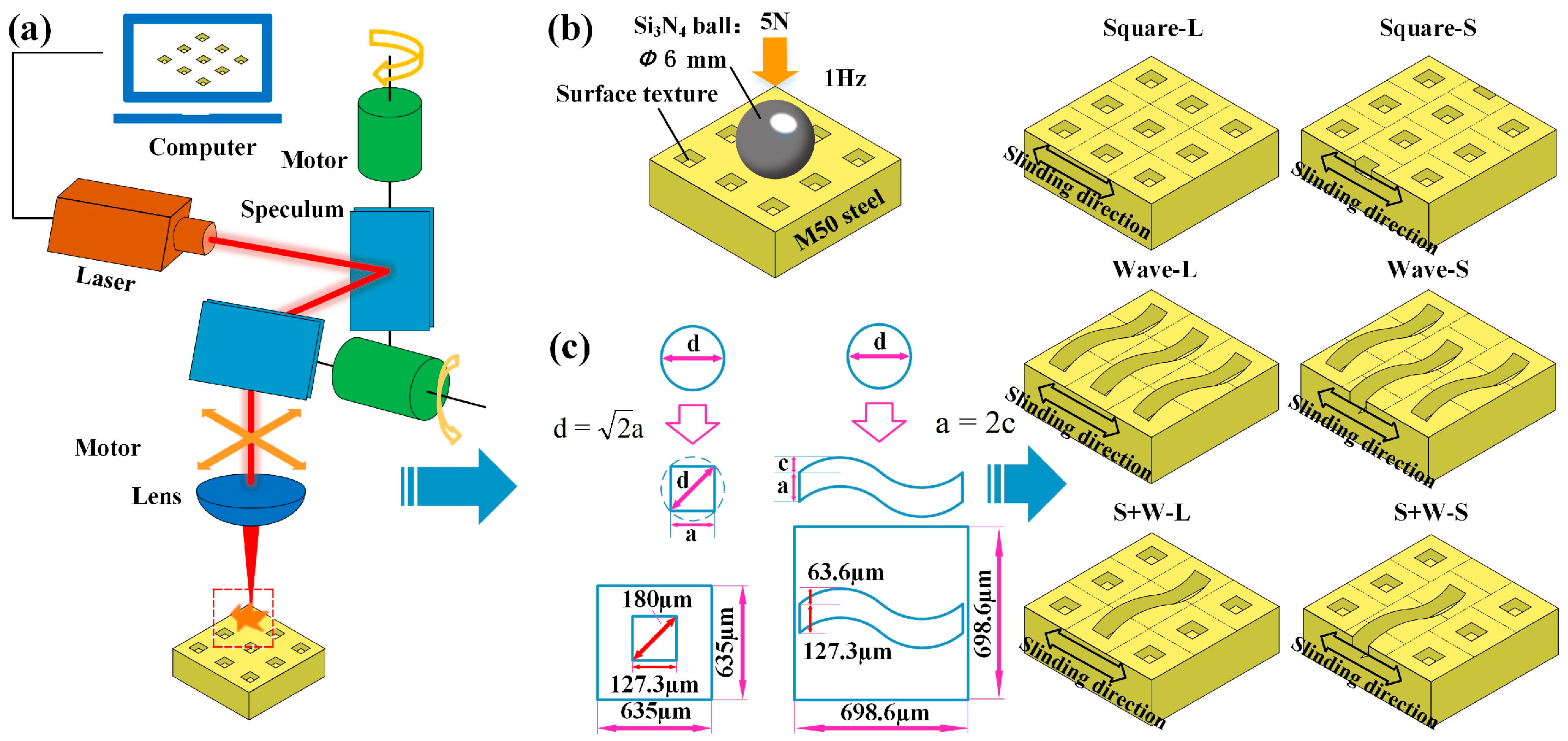
Prior to laser texturing, the samples were ultrasonically cleaned in acetone to remove surface contaminants. Surface microtexturing was carried out using a TOOL-LW-05NUV(A) laser system, with the processing principle illustrated in
Figure 1a. The laser parameters were set as follows: output power of 5 W, 30 processing passes, a scanning speed of 50 mm/s, hatch spacing of 1 μm, pulse repetition frequency of 20 kHz, and a processing diameter of 180 μm, as shown in
Figure 1c. In the figure, square (linear) is denoted as Square-L, wave (linear) as Wave-L, wave (staggered) as Wave-S, square (staggered) as Square-S, square + wave (linear) as S + W-L, and square + wave (staggered) as S + W-S.
2.2. Friction and Wear Tests
Friction and wear tests were conducted under a linear reciprocating ball-on-flat test configuration using UMT-Tribolab tribometer (Bruker, San Jose, CA, USA). The test was conducted in accordance with ASTM G133-05 standard [
15], which is widely used for evaluating the friction and wear behavior of materials under reciprocating motion. The upper specimen was a Si
3N
4 ceramic ball with a 6 mm diameter, while the opposing specimen was the M50 steel substrate. The testing parameters were as follows: applied load of 5 N, reciprocating frequency of 1 Hz, and stroke length of 5 mm. The Hertzian contact stress for the ball-on-flat pair is calculated as 1.26 GPa. The break-in period was defined as the first 100 cycles, and the total test duration was 2000 cycles. The COF was recorded in real-time by the tribometer’s software at a sampling frequency of 1 kHz. The raw data presented in the figures were smoothed using a moving average filter with a window of 2000 data points to better visualize trends. Measurements were performed under both dry conditions and with oil-lubrication (Mobil Jet Oil II, Mobil, Spring, TX, USA). For the oil-lubrication tests, a thin, uniform lubricating film was established prior to each test by applying an excess of Mobil Jet Oil II to the surface and then carefully wiping away the surplus with a lint-free cloth. This procedure created a controlled, starved lubrication condition with a consistent initial oil film, and no additional lubricant was supplied during the test. According to the datasheet of Mobil Jet Oil II provided by the manufacturer, the viscosity of the lubricating oil is 27.6 mPa·s at 40 °C, and the flash and autoignition points are 270 °C and 404 °C, respectively. All tests were conducted at room temperature, and the experimental condition set was replicated at least three times to guarantee the standard deviation of the results in each test.
2.3. Texture Performance and Wear Morphology Characterization
The surface hardness of the textured samples was measured using a Vickers hardness tester (HV-1000Z, Vickers hardness tester (SCTMC, HV-1000Z, Shanghai, China)). In hardness testing, seven test points are selected on the flat areas between textures evenly on each sample surface with a 200 g load for 15 s dwell time, and the average values of five measurement values are taken after removing the maximum and minimum values. For the statistical evaluation of the results of microhardness, one-way analysis of variance (ANOVA) tests were performed. Wear morphology before and after testing, as well as the wear scars on the Si3N4 balls, was observed using a metallographic microscope (Zeiss AxioLab.A1, Zeiss, Jena, Germany). The surface microstructure of the samples was analyzed using a scanning electron microscope (ZEISS Sigma 300). After the wear tests, wear volume (V) was obtained across the wear profiles by optical profilometry using a 3D optical profiler (Rtec UP-2000, Rtec-Instruments, San Jose, CA, USA) instrument, and the specific wear rate (k) was estimated with Archard’s wear law, k = V/(F × s) where F is the applied load and s is the total relative sliding distance. The average diameter and area density of the textures were statistically determined using Image Pro Plus software (ImageJ 1.47 version).
3. Results and Discussion
3.1. Microtextures Characterization
Figure 2 shows the surface hardness of the substrate and textured M50 steel samples. The textured samples exhibited higher hardness values than the substrate, primarily due to localized thermal effects and work hardening induced by repeated laser irradiation [
16]. The ANOVA analysis of the surface hardness for all the analyzed parameters is shown in
Table 2. The experimental parameters with the
p-value of less than 0.01 (denoted as **) significantly affect performance measures. This table shows that the differences in hardness between linear and staggered arrangements are statistically significant within the Square pattern (
p < 0.01) and the Square + Wave pattern (
p < 0.01), but not within the Wave pattern itself. Textures arranged linearly produced greater hardness than those in staggered arrangements. Moreover, the composite design combining square- and wave-shaped textures further increased the surface hardness.
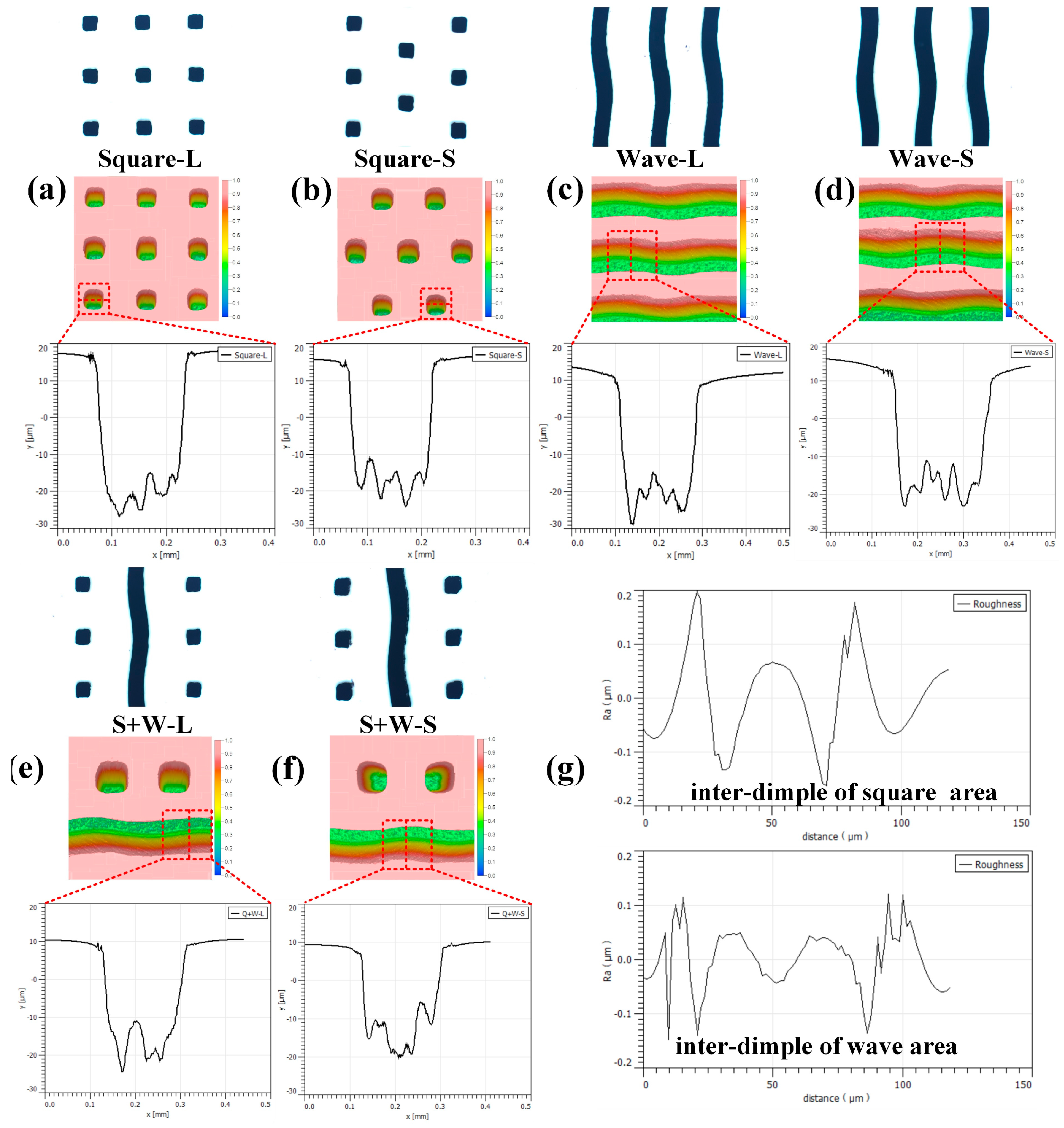
Figure 3 presents the optical images, three-dimensional morphology, and two-dimensional cross-sectional profiles of the substrate and textured M50 steel samples. The depth of the fabricated textures was approximately 30 μm. The diameters and depths of the generated textures were consistent with the designed values. The edges of the textures were smooth, but sharp protrusions were observed at the bottom due to the accumulation and solidification of molten material [
17]. Following the laser texturing process, the surface roughness of the inter-dimple areas was characterized using the 3D optical profiler (
Figure 3g). The measured
Ra values ranged from 0.1 to 0.2 μm, illustrating the increased surface roughness resulting from the laser processing, which is attributed to the laser-induced remelting and resolidification of the material surface.
3.2. Analysis of Tribological Performance
3.2.1. Dry Friction Conditions
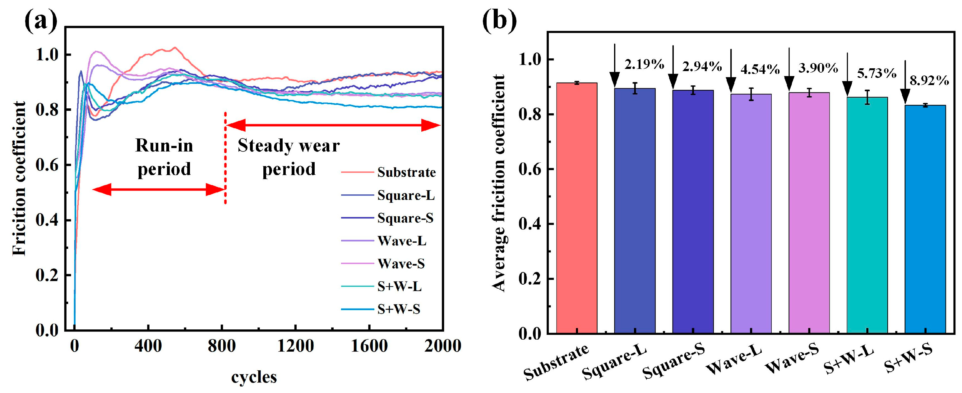
Figure 4 shows the COF curves and average values under dry friction conditions. The friction curve of the substrate exhibited significant fluctuations due to the transition from two-body to three-body wear caused by debris accumulation. Debris entering the contact area acted as rolling elements, reducing the frictional resistance. However, the shear resistance between the Si
3N
4 ball and M50 steel, along with adhesive resistance resulting from iron debris, increased the COF. During the run-in period, the small contact area led to high stress and a correspondingly high COF. As the contact area increased, the surface contact stress decreased, resulting in a slight reduction in the COF. Initially, textured M50 steel exhibited a lower COF than the substrate owing to the debris-trapping function of the textures. In the steady period, the friction curves of the different texture patterns showed no significant differences. As wear progressed, the textures were worn and filled with debris, which reduced their debris-trapping capacity and increased the COF [
18]. Overall, textured surfaces showed a lower COF than the substrate. After the single-shape textures were arranged in a composite design and staggered, the COF decreased by 8.92%, which was higher than the reduction in the wear rates of the single staggered square and wave textures (5.98% and 5.02%, respectively). Staggered textures exhibited lower COF than linear textures. We hypothesize that this is attributed to the distinct contact mechanics induced by the pit arrangements: the staggered layout more effectively disrupts the continuity of the sliding interface and provides more stable support, thereby mitigating the plowing effect and adhesive junction growth that are dominant under dry sliding conditions [
19,
20].
3.2.2. Oil-Lubrication Conditions
Figure 5 shows the friction coefficient curves and average values under oil-lubrication conditions. The substrate exhibited a COF of 0.134, and the textured surfaces showed significantly lower values. Although the differences in the average friction coefficient among the six textured conditions were marginal under these well-lubricated and mild wear conditions, a consistent and reproducible ranking was observed. Specifically, the staggered square-shaped textures (Square-S) exhibited the lowest average COF, followed by other staggered and composite designs. This suggests that even under lubrication, the arrangement and shape of textures can subtly influence lubricant retention and distribution. The staggered arrangement appears to create a more uniform network of micro-reservoirs, which is potentially a more favorable geometry for maintaining a stable lubricating film through improved secondary lubrication. The substrate demonstrated good lubrication initially; however, its COF increased slightly as the test progressed due to insufficient lubricant replenishment, a phenomenon that was effectively mitigated by the presence of surface textures. Therefore, under these stable lubrication conditions, the wear resistance and the ability to maintain a lubricating film become more critical metrics for evaluating texture performance.
3.3. Wear Morphology Analysis
3.3.1. Dry Friction
Figure 6 shows three-dimensional morphologies and two-dimensional profiles of the wear scars under dry friction. Numerous grooves formed on the M50 steel surface due to shear interaction with the hard Si
3N
4 ball. The depth and width of wear scars on textured samples were slightly smaller than those on the substrate. Most textures were worn flat, with only a small portion of the bottom structure remaining. As shown in
Figure 7, the specific wear rate for the non-textured M50 steel is maximum, and all textured samples showed lower specific wear rates compared to the substrate. This was also observed for COF, as mentioned before. The staggered textures and composite designs exhibited further improvements over linear single-shape textures, with the minimum value (~2.29 × 10
−4 mm
3/N·m) reached for the S + W-S pattern. Considering that the specific wear rates of all textured samples remain within the same order of magnitude as the untextured substrate, it can be concluded that the improvement in wear resistance under dry conditions, while statistically present, is indeed limited. The primary benefit of texturing under dry conditions appears to be more pronounced in friction reduction rather than wear resistance.
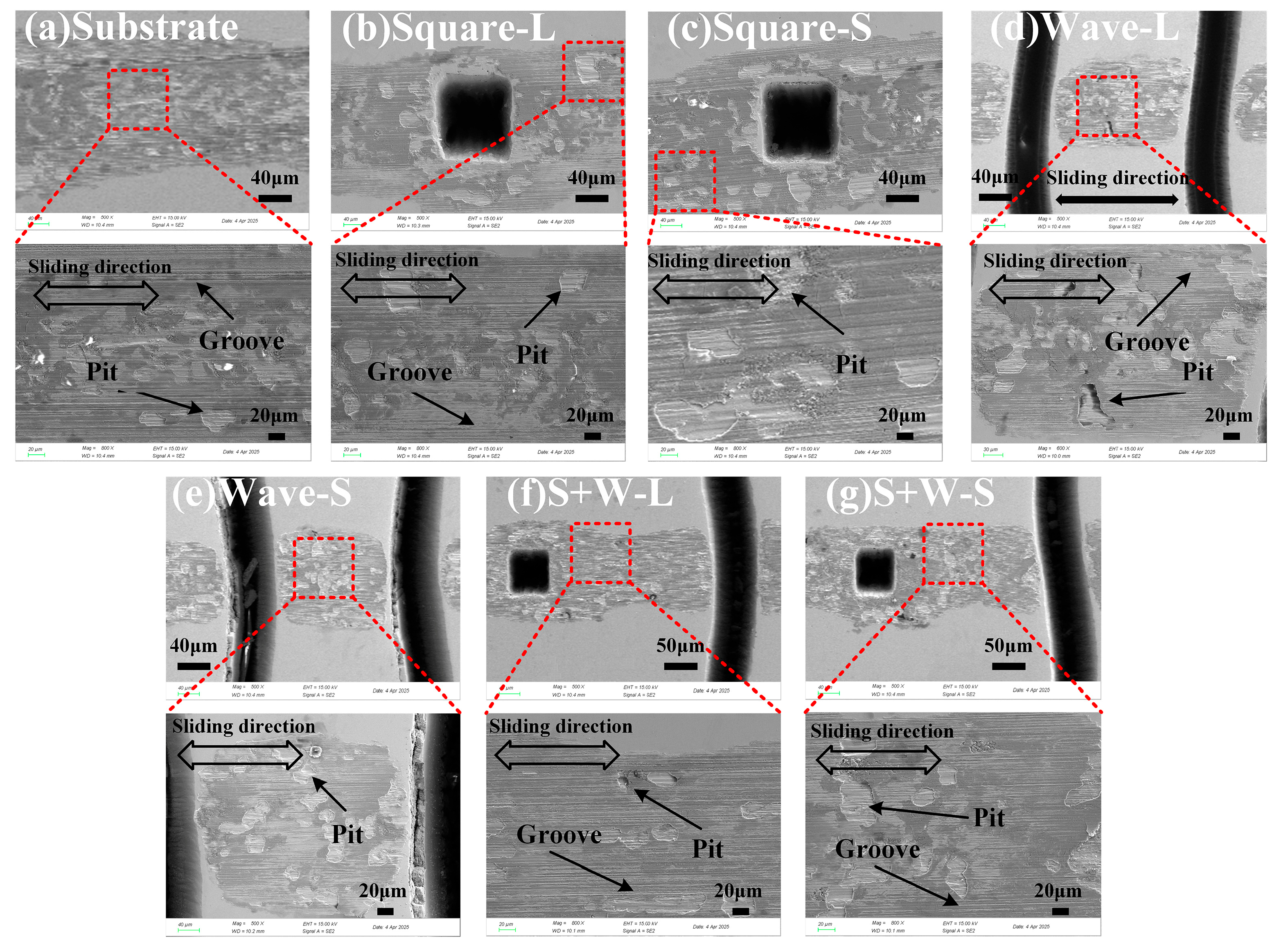
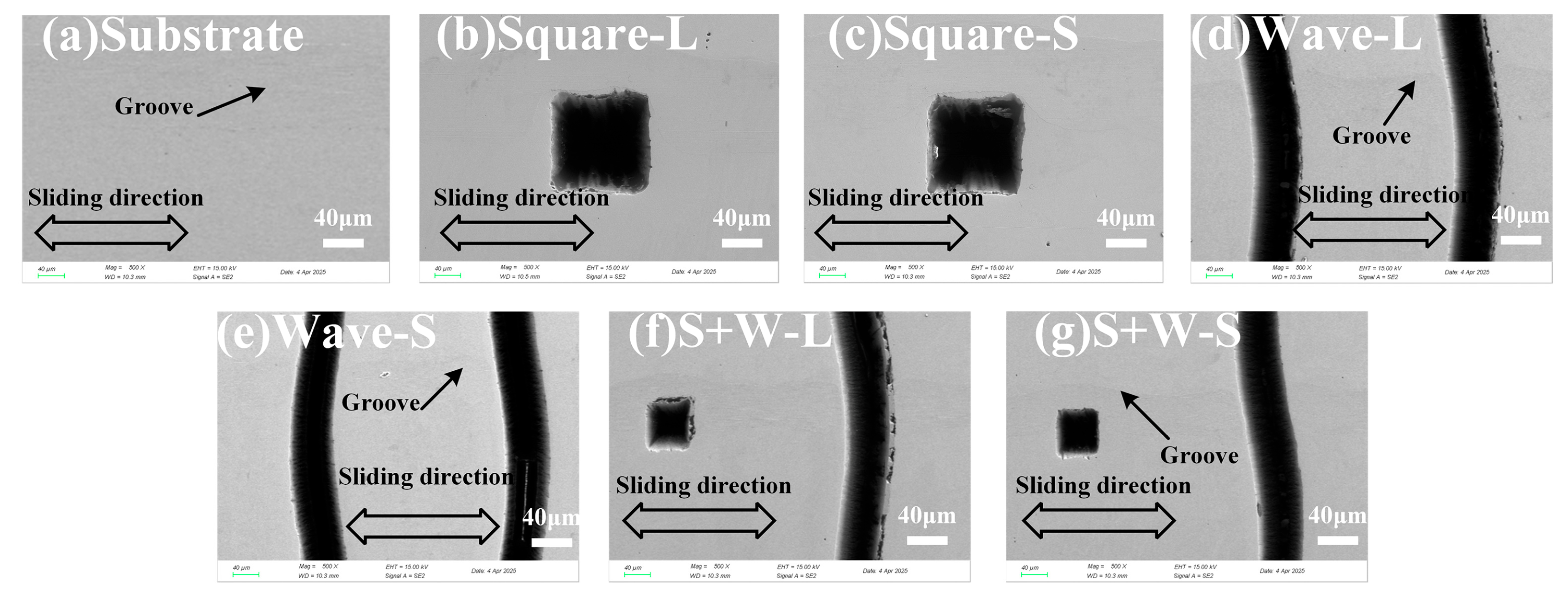
Figure 8 presents the scanning electron microscopy (SEM) images of the worn surfaces under dry friction. Prominent grooves and flaking indicated the combined effects of abrasive and adhesive wear. The hard asperities of the Si
3N
4 ball caused microcutting on the M50 steel surface, leading to abrasive wear. In addition, flaking and large pits were observed due to adhesive wear, where debris re-entered the contact area and formed adhesive sheets.
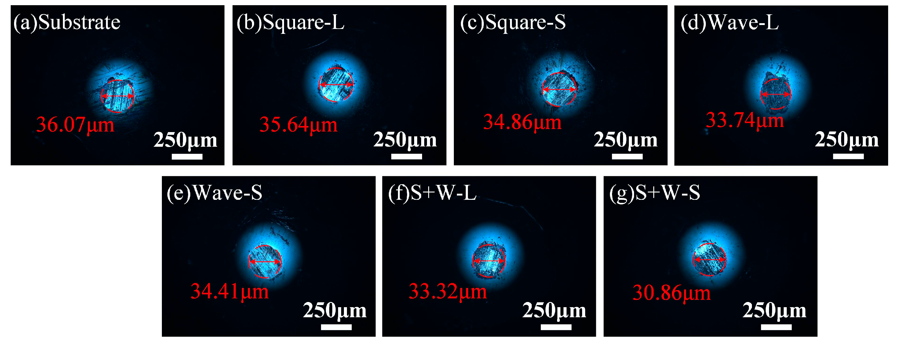
Figure 9 shows optical micrographs of wear scars on the Si
3N
4 balls after dry friction tests. The wear scar diameter after sliding against the substrate was 36 μm (
Figure 9a). The scar size decreased slightly when sliding against textured surfaces (
Figure 9b–g), but the reduction was marginal. Black adhesive layers formed on the ball surface due to oxidation of the M50 steel under reciprocating shear and frictional heat [
21]. The observed reductions in the average friction coefficient under dry conditions (
Figure 4) were corroborated by a statistically rigorous analysis of the wear performance. As detailed in
Section 3.1 (
Table 2) and
Section 3.3.1 (
Figure 7), the specific wear rates and hardness measurements were subjected to analysis of variance (ANOVA), which confirmed that the performance differences between key texture arrangements were statistically significant (
p < 0.01). This consistent trend across multiple, independent metrics—friction reduction, wear rate reduction, and hardness variation—significantly strengthens the reliability of our conclusions regarding the superiority of staggered and composite textures.
3.3.2. Oil Lubrication
Figure 10 shows the wear morphology under oil lubrication. The substrate surface exhibited distinct wear scars, indicating direct contact with the counterface caused by lubricant dissipation. In contrast, textured surfaces showed minimal wear, with only slight deformation at the texture edges. The textures were filled with debris, which provided secondary lubrication and prevented further damage from hard particles [
22].
Figure 11 presents SEM images of the worn surfaces under oil-lubrication. Wear was mild on both the substrate and textured surfaces, with fine grooves indicating slight abrasive wear. Textured surfaces, particularly the wave-staggered pattern (
Figure 10e), showed almost no visible scratches owing to the oil reservoir and secondary lubrication effects. Lubricant released from the textures improved the lubrication conditions at the interface.
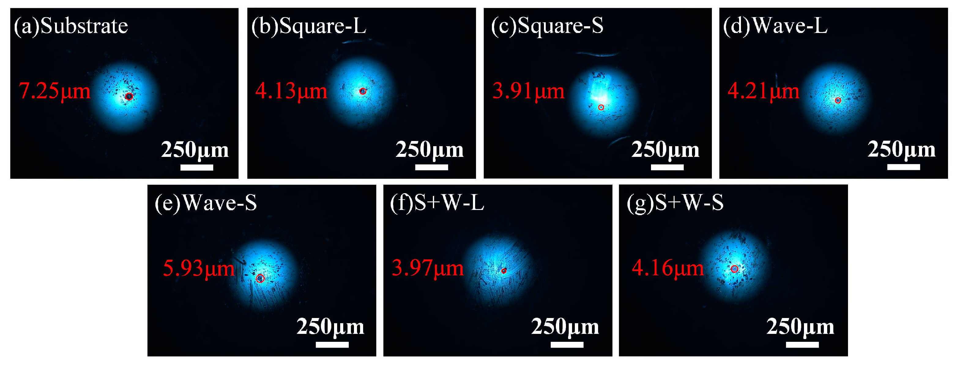
Figure 12 shows optical micrographs of wear scars on the Si
3N
4 balls under oil lubrication. Compared with dry conditions, the scar diameters were significantly smaller, ranging from 3.9 to 5.9 μm, indicating much lower wear rates. The scar diameter after sliding against the substrate was 7.2 μm. Textured surfaces with Square-L, Square-S, square + wave-linear, and square + wave-staggered arrangements (
Figure 12b,c,f,g) produced smaller and lighter-colored scars, suggesting improved lubrication [
23]. An interesting observation is the role of texture arrangement under oil-lubricated conditions. Although the linearly arranged textures resulted in a marginally higher surface hardness, the staggered patterns (particularly Square-S) demonstrated superior tribological performance. This apparent discrepancy underscores that in lubricated sliding, the enhanced lubrication and lubricant reservoir effects provided by the texture layout are the dominant factors controlling friction and wear. The performance benefits of optimized lubricant entrapment and distribution in the staggered arrangement outweigh the incremental advantage offered by the slightly higher hardness of the linear patterns.
Figure 13 illustrates the wear mechanisms pertaining to the different texture arrangements. Under dry friction conditions, the textures primarily trapped debris, reducing abrasive wear. Staggered arrangements facilitated greater debris capture, improving the wear resistance. Under oil-lubrication conditions, textures acted as lubricant reservoirs, providing secondary lubrication during sliding. Based on the superior tribological performance observed, we hypothesize that staggered arrangements may promote more efficient lubricant entrapment and distribution, which helps to maintain a more continuous lubricant film at the interface. This hypothesized mechanism of improved lubricant supply could contribute to the observed friction and wear reduction. Compared with single-shape textures, the composite design (square + wave) with a linear arrangement showed better hydrodynamic lubrication performance. Overall, staggered arrangements outperformed linear patterns in reducing wear and friction under dry and oil-lubrication conditions. A future study involving computational fluid dynamics (CFD) modeling based on the actual texture parameters is planned to quantitatively validate this hydrodynamic pressure hypothesis.
4. Conclusions
This study fabricated various surface textures on M50 steel via laser processing and systematically investigated the tribological behavior under dry and oil-lubrication conditions. The main conclusions were as follows:
(1) Under dry friction, textures effectively reduced the COF compared to the non-textured substrate. The composite staggered (S + W-S) texture achieved a maximum COF reduction of 8.92%. Furthermore, its specific wear rate was minimized at 2.29 × 10⁻⁴ mm3/N·m. While staggered textures exhibited superior anti-wear performance by trapping more debris, they resulted in a lower COF than linear textures, which we hypothesize is less frequent contact with the texture pits.
(2) Under oil-lubrication conditions, abrasive wear was the dominant wear mechanism. The superior performance of staggered textures is potentially attributed to their more effective role as lubricant reservoirs, which enhances secondary lubrication and promotes the formation of a more stable lubricating film. This resulted in better friction reduction and antiwear performance compared with surfaces with no textures or linear textures. While the texture pits can retain solid particles, our experimental results indicate that their primary role under oil-lubrication was beneficial, likely by sequestering debris away from the primary sliding contact and preventing it from participating in three-body abrasion, rather than enhancing the abrasive process.
(3) All texture types acted as debris traps or lubricant reservoirs, but their effectiveness depended on frictional resistance and surface hardness. The surface hardness, validated by ANOVA, was significantly increased (p < 0.01) by texturing, with the composite linear (S + W-L) pattern achieving the highest value of 715.46 HV. Rational design of texture shape and arrangement can produce synergistic effects, further enhancing the tribological performance of M50 steel.
In summary, this study highlights that the arrangement of texture patterns is a non-negligible factor for optimizing the tribological performance of M50 steel. While further validation in real-world components is needed, the consistent superiority of staggered arrangements suggests a promising potential for enhancing reliability through improved debris and lubricant control.
Author Contributions
Conceptualization and methodology, X.X.; investigation and writing—original draft preparation, R.C. and J.Y.; formal analysis and funding acquisition, J.L. All authors have read and agreed to the published version of the manuscript.
Funding
This research was funded by the Science and Technology Planning Project of Guizhou Province (ZK [2022]013); Guizhou Province Hundred Level Innovative Talents (Qiankehe Platform Talents GCC [2023]005); Guizhou Key Laboratory of Advanced Low-Dimensional Green Energy Storage Materials in Universities ([2022]056); the Research and Innovation Team for Water Ion Battery Materials in Higher Education Institutions in Guizhou Province ([2023]081); College Students’ Innovation Training Program (202510976682).
Data Availability Statement
The original contributions presented in this study are included in the article. Further inquiries can be directed to the corresponding authors.
Conflicts of Interest
The authors declare no conflicts of interest.
References
- Su, Y.; Yang, S.; Yu, X.; Zhou, C.; Liu, Y.; Feng, X.; Zhao, Q.; Wu, J. Effect of austempering temperature on microstructure and mechanical properties of M50 bearing steel. J. Mater. Res. Technol. 2022, 20, 4576–4584. [Google Scholar] [CrossRef]
- Yu, X.; Zheng, D.; Yang, X.; Wang, S.; An, M.; Yan, G.; Xia, Y.; Xing, F. Effect of carbide precipitation behavior at high temperatures on microstructure and mechanical properties of M50 steel. J. Mater. Res. Technol. 2022, 18, 1155–1165. [Google Scholar] [CrossRef]
- Xie, X.; Chen, C.; Luo, J.; Xu, J. The microstructure and tribological properties of M50 steel surface after titanium ion implantation. Appl. Surf. Sci. 2021, 564, 150349. [Google Scholar] [CrossRef]
- Venkatesh, B.; Reddy, C.A.K. Experimental study on heat treatment and mechanical behaviour of M50 NiL steel—A review. Mater. Today Proc. 2021, 46, 795–798. [Google Scholar] [CrossRef]
- Huang, Q.; Shi, X.; Ma, J. Tribological behavior of surface bionic rhombic-textured M50 steel containing SnAgCu and MXene-Nb2C under dry sliding conditions. J. Mater. Eng. Perform. 2021, 30, 9390–9402. [Google Scholar] [CrossRef]
- Lai, F.; Cao, C.; Chen, H.; Lin, C.; Song, C.; Lei, K.; Lin, Y.; Wu, Z. Influence of micro-groove surface texture on the lubrication tribological properties of GCr15 bearing steel. Proc. Inst. Mech. Eng. Part J J. Eng. Tribol. 2025, 239, 13506501241313247. [Google Scholar] [CrossRef]
- Khan, M.A.; Halil, A.M.; Abidin, M.S.Z.; Hassan, M.H.; Ab Rahman, A.A. Influence of laser surface texturing on the surface morphology and wettability of metals and non-metals: A review. Mater. Today Chem. 2024, 41, 102316. [Google Scholar] [CrossRef]
- Patel, D.; Jain, V.; Ramkumar, J. Micro texturing on metallic surfaces: State of the art. Proc. Inst. Mech. Eng. Part B J. Eng. Manuf. 2018, 232, 941–964. [Google Scholar] [CrossRef]
- Qiu, Y.; Khonsari, M. Experimental investigation of tribological performance of laser textured stainless steel rings. Tribol. Int. 2011, 44, 635–644. [Google Scholar] [CrossRef]
- Lu, L.; Zhang, Z.; Guan, Y.; Zheng, H. Comparison of the effect of typical patterns on friction and wear properties of chromium alloy prepared by laser surface texturing. Opt. Laser Technol. 2018, 106, 272–279. [Google Scholar] [CrossRef]
- Long, R.; Zhao, C.; Jin, Z.; Zhang, Y.; Pan, Z.; Sun, S.; Gao, W. Influence of groove dimensions on the tribological behavior of textured cylindrical roller thrust bearings under starved lubrication. Ind. Lubr. Tribol. 2021, 73, 971–979. [Google Scholar] [CrossRef]
- Zhang, C.; Gu, L.; Tang, G.; Mao, Y. Wear transition of CrN coated M50 steel under high temperature and heavy load. Coatings 2017, 7, 202. [Google Scholar] [CrossRef]
- Segu, D.Z.; Hwang, P. Effectiveness of multi-shape laser surface texturing in the reduction of friction under lubrication regime. Ind. Lubr. Tribol. 2016, 68, 116–124. [Google Scholar] [CrossRef]
- Laki, G.; Nagy, A.L.; Rohde-Brandenburger, J.; Hanula, B. A review on friction reduction by laser textured surfaces in internal combustion engines. Tribol. Online 2022, 17, 318–334. [Google Scholar] [CrossRef]
- ASTM Standard G133-05; Standard Test Method for Linearly Reciprocating Ballon-Flat Sliding Wear. ASTM Int.: West Conshohocken, PA, USA, 2016. [CrossRef]
- Wang, B.; Zheng, M.; Zhang, W. Analysis and prediction of wear performance of different topography surface. Materials 2020, 13, 5056. [Google Scholar] [CrossRef]
- Chen, Z.; Zhou, J.; Cen, W.; Yan, Y.; Guo, W. Femtosecond Laser Fabrication of Wettability-Functional Surfaces: A Review of Materials, Structures, Processing, and Applications. Nanomaterials 2025, 15, 573. [Google Scholar] [CrossRef] [PubMed]
- Ji, M.; Xu, J.; Chen, M.; El Mansori, M. Enhanced hydrophilicity and tribological behavior of dental zirconia ceramics based on picosecond laser surface texturing. Ceram. Int. 2020, 46, 7161–7169. [Google Scholar] [CrossRef]
- Shimizu, J.; Nakayama, T.; Watanabe, K.; Yamamoto, T.; Onuki, T.; Ojima, H.; Zhou, L. Friction characteristics of mechanically microtextured metal surface in dry sliding. Tribol. Int. 2020, 149, 105634. [Google Scholar] [CrossRef]
- Rosenkranz, A.; Grützmacher, P.G.; Gachot, C.; Costa, H.L. Surface texturing in machine elements—A critical discussion for rolling and sliding contacts. Adv. Eng. Mater. 2019, 21, 1900194. [Google Scholar] [CrossRef]
- Hager, C.H., Jr.; Evans, R.D. Friction and wear properties of black oxide surfaces in rolling/sliding contacts. Wear 2015, 338, 221–231. [Google Scholar] [CrossRef]
- Czichos, H. Tribology: A Systems Approach to the Science and Technology of Friction, Lubrication, and Wear; Elsevier: Amsterdam, The Netherlands, 2009; Volume 1. [Google Scholar]
- Elsheikh, A.H.; Yu, J.; Sathyamurthy, R.; Tawfik, M.; Shanmugan, S.; Essa, F. Improving the tribological properties of AISI M50 steel using Sns/Zno solid lubricants. J. Alloys Compd. 2020, 821, 153494. [Google Scholar] [CrossRef]
Figure 1.
(a) Schematic diagram of laser microtexturing processing; (b) schematic diagram of friction pair; (c) schematic diagram of texture distribution with different arrangement modes.
Figure 1.
(a) Schematic diagram of laser microtexturing processing; (b) schematic diagram of friction pair; (c) schematic diagram of texture distribution with different arrangement modes.
Figure 2.
Surface hardness of M50 steel samples.
Figure 2.
Surface hardness of M50 steel samples.
Figure 3.
Optical microscopic images, 3D profiles, and 2D cross-sectional views of M50 steel: (a) Square-L; (b) Square-S; (c) Wave-L; (d) Wave-S; (e) S + W-L; (f) S + W-S; (g) representative surface roughness measurement of the inter-dimple area for the S + W-S.
Figure 3.
Optical microscopic images, 3D profiles, and 2D cross-sectional views of M50 steel: (a) Square-L; (b) Square-S; (c) Wave-L; (d) Wave-S; (e) S + W-L; (f) S + W-S; (g) representative surface roughness measurement of the inter-dimple area for the S + W-S.
Figure 4.
Friction coefficient curves and average friction coefficients of M50 steel samples under dry friction conditions: (a) friction coefficient curve; (b) average friction coefficients.
Figure 4.
Friction coefficient curves and average friction coefficients of M50 steel samples under dry friction conditions: (a) friction coefficient curve; (b) average friction coefficients.
Figure 5.
M50 steel samples under oil-lubrication: (a) friction coefficient curve; (b) average friction coefficients.
Figure 5.
M50 steel samples under oil-lubrication: (a) friction coefficient curve; (b) average friction coefficients.
Figure 6.
Three-dimensional profiles and two-dimensional contour maps of wear morphologies of substrate and textured M50 steel samples under dry friction (load: 5 N, frequency: 1 Hz, stroke: 5 mm): (a) Substrate; (b) Square-L; (c) Square-S; (d) Wave-L; (e) Wave-S; (f) S + W-L; (g) S + W-S.
Figure 6.
Three-dimensional profiles and two-dimensional contour maps of wear morphologies of substrate and textured M50 steel samples under dry friction (load: 5 N, frequency: 1 Hz, stroke: 5 mm): (a) Substrate; (b) Square-L; (c) Square-S; (d) Wave-L; (e) Wave-S; (f) S + W-L; (g) S + W-S.
Figure 7.
Specific wear rate of M50 steel samples under dry friction.
Figure 7.
Specific wear rate of M50 steel samples under dry friction.
Figure 8.
SEM images of surface wear morphologies of substrate and textured M50 steel samples under dry friction: (a) Substrate; (b) Square-L; (c) Square-S; (d) Wave-L; (e) Wave-S; (f) S + W-L; (g) S + W-S.
Figure 8.
SEM images of surface wear morphologies of substrate and textured M50 steel samples under dry friction: (a) Substrate; (b) Square-L; (c) Square-S; (d) Wave-L; (e) Wave-S; (f) S + W-L; (g) S + W-S.
Figure 9.
Optical microscopic images of wear morphologies of Si3N4 ceramic balls under dry friction: (a) Substrate; (b) Square-L; (c) Square-S; (d) Wave-L; (e) Wave-S; (f) S + W-L; (g) S + W-S.
Figure 9.
Optical microscopic images of wear morphologies of Si3N4 ceramic balls under dry friction: (a) Substrate; (b) Square-L; (c) Square-S; (d) Wave-L; (e) Wave-S; (f) S + W-L; (g) S + W-S.
Figure 10.
Three-dimensional profiles and two-dimensional contour maps of wear morphologies of substrate and textured M50 steel samples under oil-lubrication: (a) Substrate; (b) Square-L; (c) Square-S; (d) Wave-L; (e) Wave-S; (f) S + W-L; (g) S + W-S.
Figure 10.
Three-dimensional profiles and two-dimensional contour maps of wear morphologies of substrate and textured M50 steel samples under oil-lubrication: (a) Substrate; (b) Square-L; (c) Square-S; (d) Wave-L; (e) Wave-S; (f) S + W-L; (g) S + W-S.
Figure 11.
SEM images of surface wear morphologies of substrate and textured M50 steel samples under oil-lubrication.
Figure 11.
SEM images of surface wear morphologies of substrate and textured M50 steel samples under oil-lubrication.
Figure 12.
Optical microscopic images of the wear morphologies of Si3N4 ceramic balls under oil-lubrication conditions.
Figure 12.
Optical microscopic images of the wear morphologies of Si3N4 ceramic balls under oil-lubrication conditions.
Figure 13.
Schematic of wear mechanisms of textured M50 steel specimens with different textures under (a) dry and (b) oil-lubrication conditions.
Figure 13.
Schematic of wear mechanisms of textured M50 steel specimens with different textures under (a) dry and (b) oil-lubrication conditions.
Table 1.
Chemical composition of M50 steel.
Table 1.
Chemical composition of M50 steel.
| Element | C | Cr | Mo | V | Mn | Fe |
|---|
| wt.% | 0.80 | 4.02 | 4.05 | 0.95 | 0.25 | Bal. |
Table 2.
ANOVA for surface hardness of the textured samples.
Table 2.
ANOVA for surface hardness of the textured samples.
| Source | Linear Textures | Staggered Textures | Factor Value | p (Probability Value) |
|---|
| Square | 706.48 ± 3.00 | 691.66 ± 2.79 | 65.464 | <0.001 ** |
| Wave | 701.54 ± 3.16 | 700.64 ± 3.02 | 0.212 | 0.657 |
| Square + Wave | 715.46 ± 3.20 | 706.48 ± 3.00 | 20.929 | 0.002 ** |
| Disclaimer/Publisher’s Note: The statements, opinions and data contained in all publications are solely those of the individual author(s) and contributor(s) and not of MDPI and/or the editor(s). MDPI and/or the editor(s) disclaim responsibility for any injury to people or property resulting from any ideas, methods, instructions or products referred to in the content. |
© 2025 by the authors. Licensee MDPI, Basel, Switzerland. This article is an open access article distributed under the terms and conditions of the Creative Commons Attribution (CC BY) license (https://creativecommons.org/licenses/by/4.0/).
