Abstract
Bipolar plates are one of the main components of proton exchange membrane fuel cells (PEMFCs). Their functions include distributing reactants, supporting the cell, and conducting heat and electricity. They account for a significant proportion of the fuel cell stack’s weight and volume. The main materials currently used for bipolar plates are graphite and stainless steel. Aluminium has a much lower density than steel and is easier to form than both steel and graphite. Its use, therefore, would allow fuel cells with higher power densities but is hindered due to it being prone to corrosion. This work focused on the development of corrosion-resistant and conductive coatings to address this issue. Carbon coatings with Ti and Cr adhesion layers were deposited on aluminium substrates using closed-field unbalanced magnetron sputtering. These coatings were tested for corrosion properties and performance on the cathode side of a single-cell fuel cell. Coated aluminium samples were also tested for their ability to maintain their corrosion protection after being formed. Coating with a Cr adhesion layer outperformed that with a Ti adhesion layer in both forming and fuel cell tests, demonstrating much lower performance degradation after accelerated stress testing.
1. Introduction
PEMFCs have great potential in converting hydrogen and oxygen into electrical energy, heat, and water, with no pollutant emissions and very high electrical energy efficiency. Two of the most important components of a PEMFC are the membrane electrode assembly (MEA) and bipolar plate (BPP) [1,2]. The main purpose of the bipolar plate is to distribute the reactant gases, provide an electrically conductive pathway, and facilitate water removal from the cell [3]. Bipolar plates have traditionally been fabricated from graphite or carbon composite materials due to their chemical stability. However, carbon-based bipolar plates have poor mechanical properties and high manufacturing costs [4]. Metallic bipolar plates are an alternative to carbon plates, with stainless steel being the dominant bipolar plate material, especially for transport applications.
Air-cooled fuel cells are particularly suitable for lower-power automotive applications, such as primary and range extender drives for lightweight vehicles. Their rapid refuelling capabilities, combined with significantly reduced balance-of-plant complexity, minimise weight and costs and provide a clear differentiator from a pure battery-powered solution. Stainless steel BPPs are currently the most common BPPs used in these fuel cells. Aluminium offers good mechanical performance and availability for mass production. Also, it is approximately 60% lighter than stainless steel; hence, it can result in a considerable increase in the specific power of PEMFC (up to a three-fold increase). Additionally, aluminium has low bulk electrical resistivity (a fifth of stainless steel) and high thermal conductivity (around 10 times higher than stainless steel, depending on the grade/alloy), combined with ease of fabrication and considerably lower costs. Nevertheless, insufficient corrosion resistance and surface conductivity restrict aluminium BPPs from wider application. Therefore, appropriate surface modification is essential for the technological and commercial viability of aluminium BPPs. The development of high-performance, low-cost coatings, compatible with conventional downstream plate manufacturing processes, will make aluminium BPPs a very attractive option for lightweight PEMFCs.
A critical requirement for Al BPP coatings is to be pinhole-free, to prevent aluminium from corroding. Moreover, the coatings require high conductivity. A number of coatings have been evaluated for aluminium-based BPPs. The application of nickel and nickel alloys has been reported in several studies [5,6,7,8,9]. Electroless nickel followed by heat treatment at 500 °C, with an additional gold coating to provide conductivity, has been reported to improve the corrosion resistance of Al6061 alloy [5]. The coating improved the corrosion resistance of the Al alloy. However, no data have been reported on the in situ performance of this coating. Abo El-Enin et al. [7] investigate the electroplating of a number of Ni alloys on aluminium substrates and achieved good corrosion resistance but did not provide results on conductivity, and/or in situ fuel cell performance of the coated plates. Fetohi et al. [8] also reported improved corrosion resistance of Ni-alloy-coated Al, which also achieved improved conductivity. The lowest ICR obtained was 27 mΩ cm2, which is higher than the USA DOE target value of 10 mΩ cm2 [10]. Madadi et al. [9] also reported the improvement in corrosion resistance and conductivity of aluminium bipolar plates, as well as better performance of coated plates in single-cell fuel cell tests compared to uncoated aluminium bipolar plates. Durability testing was performed for 19,000 s.
The use of chromium carbide with a Cr-C-Ni interlayer, deposited by the thermal spraying method, was also reported [11]. The coatings were up to 300 µm, which can affect the weight and recovery of the plates. Furthermore, during stack testing, membrane failure was observed.
Lee et al. [12] used a chemical treatment method to enhance the corrosion resistance of aluminium bipolar plates. However, they noted a negative effect on the conductivity of the plates, which led to lower performance of the fuel cell.
Conductive-polymer composite coatings have also been studied for aluminium bipolar plates. Lee et al. [13] used this method and found that, whilst the coatings improved corrosion resistance, the electrical conductivity was not ideal. However, conductivity improved through the addition of conductive carbon black or carbon paper to the composite coating. Mawdsley et al. [14] reported that both corrosion performance and through-plane conductivity were inadequate due to the undesirable microstructure of the coating, which included porosity and pinholes.
The use of PVD for the coating of aluminium bipolar plates was evaluated by Lee et al. [15] who compared the performance of a PVD-deposited diamond-like carbon with uncoated stainless steel and graphite. Whilst the coated Al improved the fuel cell performance compared to uncoated stainless steel, due to the increased ohmic resistance of the latter, the performance of the plates was lower compared with graphite plates.
Narasimharaju et al. [16] reviewed some of the advances in coatings for aluminium-based bipolar plates. There are still many gaps in the research and deployment of coated aluminium bipolar plates for PEMFCs. The combination of high corrosion resistance and conductivity, as well as durability of the coatings within fuel cell operating conditions, has not yet been demonstrated. It is clear that the main focus should be on the development of highly corrosion-resistance, pin-hole-free coatings, with good electrical conductivity. Carbon coatings have been extensively evaluated for bipolar plate coatings based on stainless steel and titanium [17,18,19]. This work evaluates dense, PVD-deposited carbon coatings for aluminium-based bipolar plates.
2. Materials and Methods
2.1. Coating Preparation
Carbon coatings of approximately 700–800 nm in thickness were deposited using a Teer UDP 650 Closed Field Unbalanced Magnetron Sputter Ion Plating system (Teer Coatings Ltd, Droitwich, UK). Prior to coating, aluminium coupons (grade 6082 alloy) (50 × 50 × 1 mm3) and a witness sample of M42 tool steel (30 mm diameter, 3 mm thick) were ultrasonically cleaned in acetone for 15 min, followed by drying in warm air. The samples were arranged onto the substrate holder and introduced into the coating chamber at a substrate-to-target distance of 15 cm The chamber was then pumped down to a pressure of 0.0027 Pa (2 × 10⁻⁵ torr). Argon (99.998% purity) was then admitted by a mass flow controller, allowing the chamber to reach the desired deposition pressure. The coupons were first ion-cleaned by applying a pulsed DC bias voltage of −350 V, during which the magnetrons (2 with chromium or titanium (both 99.5% purity) and 2 with isotropic graphite targets) were all operated at 0.4 A. This was done in order to intensify the ion-cleaning plasma, but without creating a significant coating flux onto the substrate. The coupons were then sputtered with a thin Cr or Ti layer using a current of 4 A on the target, followed by a gradient layer with increasing carbon and decreasing chromium content. Finally, a top layer of pure carbon was deposited using 3.5 A on two carbon targets, during which the pulsed DC bias was reduced to −80 V. The coating thickness, including both the interlayer and the top carbon layer, was measured using the ball cratering method.
2.2. Characterisation
Coating adhesion was evaluated using the Rockwell indentation test [20]. The test was performed on coated M42 test pieces using a ZwickRoell ZHR Rockwell tester (ZwickRoell, Worcester, UK) at a load of 150 kg.
Thickness was measured using the ball-cratering method.
Post-mortem evaluation of the tested plates was performed using a Cambridge Stereoscan 200 (Cambridge Instruments, Cambridge, UK) and a Zeiss EVO 15 (Carl Zeiss Microscopy Gmbh, Jena, Germany) SEM and EDX. For EDX measurements, at least three spots were measured, and the average value was reported.
2.3. Interfacial Contact Resistance (ICR) Measurement
Figure 1 shows the setup used for the ICR measurements. ICR values were taken before and after each electrochemical test. The aluminium coupon, positioned with a Freudenberg I2C6 gas diffusion layer (GDL) (Freudenberg, Weinheim, Germany) and cut to the shape of the sample, was placed between two gold-coated copper conducting electrodes. The variation in the total interfacial contact resistance between the two electrodes was recorded at the compressive stress of 140 MPa. The total interfacial contact resistance (RT, Equation (1)) calculated includes the ICR of the top gold electrode/GDL (Rgold/GDL), the GDL/metal sample (RGDL/sample), and the bottom gold electrode (Rgold/GDL). The Rgold/GDL was deduced from previous testi ng and, therefore, RGDL/sample could be calculated (Equation (2)). Also, it was assumed that the bulk resistances of the aluminium coupon, gold and copper conducting plates and the GDL were negligible.
RT = Rgold/GDL + RGDL/sample,
RGDL/sample = RT − Rgold/GDL.
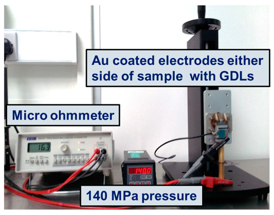
Figure 1.
The setup used for the measurement of ICR.
Before each analysis, a gold-coated sample was tested as the reference to confirm the measurement.
2.4. Corrosion Testing
Corrosion testing was carried out in a three-electrode setup, where the aluminium coupon (working electrode) and a platinum mesh (counter electrode) were submerged in a 1 mM H2SO4 electrolyte. The reference electrode, Hg/Hg2SO4/K2SO4 at (0.8 V vs. SHE), was connected to the electrolyte compartment by a salt bridge. The electrolyte was heated to 55 °C. All standard potentials mentioned in this work are vs. the standard hydrogen potential (SHE). A PalmSens EmStat potentiostat (PalmSens, Houten, Netherlands) was used to perform potentiostatic measurements at 0.8 V vs. SHE for electrolyte concentrations of 1 mM, for a period of 1 h, with bubbling air to simulate the cathode corrosion environment.
2.5. Fuel Cell Testing
Single-cell fuel cell testing was performed in a Scribner 850e fuel cell station (Scribner LLC, Southern Pines, NC, USA) at the University of Birmingham.
The MEA used for the measurements was a Ballard catalyst-coated Nafion membrane (CCM) (Ballard Power Systems, Bend, OR, USA), with a catalyst loading of 0.4 mg cm−2. The operating temperature was 55 °C. A Freudenberg I2C6 gas diffusion layer (GDL) was used.
Single cells were manufactured using a graphite plate for the anode side and a coated aluminium plate for the cathode side. Serpentine geometry with a total length of 392.4 mm was used. The channels had a rectangular cross-section (1 mm wide and 1 mm deep), spaced by 1 mm wide ribs. The active area was 25 mm × 25 mm.
Before the MEA underwent any testing it was conditioned at 80 °C with 100% relative humidity, anode back pressure of 150 kPa and cathode back pressure of 130 kPa, anode inlet of hydrogen and cathode inlet of air (1.3 and 1.5 stoichiometry, respectively) for 15 h. Once the membrane was fully hydrated, the cells were cooled down to 55 °C, and the relative humidity was set to 50% for anode and 30% for the cathode for accelerated stress test (AST).
Then, charge cycles began every 25 s, changing the voltage between 0.6 V (10 s) and 0.9 V (15 s), the test was stopped after 1700 cycles (12 h), when polarisation curves and EIS were obtained, before another 1700 cycles. This was repeated a total of 11 times. The polarization curve was recorded from OCV to 0.25 V. EIS measurement was performed in the frequency range from 10 kHz to 0.1 Hz with an amplitude of 10% of DC at 0.6 V. Figure 2 shows the test setup.
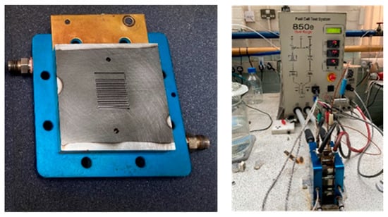
Figure 2.
The bipolar plate and fuel cell test setup.
2.6. Simple Stamping Trial
In order for the production of lightweight bipolar plates to be industrially scalable, it is desirable to coat reels of foil, followed by creating the channels through stamping. This will enable the use of high-throughput coating methods, such as roll-to-roll coating processes. For this to be viable, the coating should be able to stand the stamping process without cracking or formation of defects, which could result in the corrosion of the substrate.
Stamping trials were performed using a set of dies, which were designed to generate a corrugated pattern on the foil surface representing the bipolar plate channels. Five channels (with a length of 10 mm, width of 1 mm, and 0.5 mm deep) were created on the coated foils using a pressure of 1.4 MPa and at a speed of 1 mms−1. The dies and the pattern generated are shown in Figure 3. The coated foil underwent stamping after coating in order to evaluate the coating integrity after stamping.

Figure 3.
(a) The die set used for the simple stamping trial, and (b) the generated pattern on an aluminium foil.
3. Results
Carbon coatings have been widely used on metallic BPPs in order to improve corrosion resistance and conductivity, especially in the case of stainless-steel plates [21,22,23]. This is due to their high electrical conductivity, good level of corrosion resistance and low cost. An interlayer is normally required in order to enhance the adhesion of carbon coating to the substrate. Cr is normally applied as the base layer for carbon coatings. The interlayer has the additional function of providing corrosion resistance. It should therefore be electrochemically stable, dense and free of pinholes and defects.
The stability of sputtered carbon coatings with Cr interlayers during electrochemical testing is dependent on the potential applied. At potentials of up to 1.2 V vs. SHE, the coating can have good corrosion resistance. At higher potentials, however, the Cr interlayer is delaminated from the substrate, making Cr an unsuitable material for application at high potentials [17]. As this work focuses on low-potential applications, the use of Cr was not expected to present a problem. However, Ti was also used as an alternative base layer as it is more suitable for applications in which higher potentials are experienced.
The starting deposition parameters used in this work were based on those developed in a previous study [24], which provided good protection for stainless steel bipolar plates. As the corrosion protection requirements are more stringent in the case of aluminium plates, further optimisation was performed in order to improve the coatings. The deposition pressure during carbon sputtering is known to affect the intrinsic stress and hardness of the carbon film [25,26]. It has also been reported that the resistivity and corrosion resistance of carbon films can be influenced by the deposition pressure [27]. Therefore, in this work, three Ti-C coatings were deposited using Ar flow rates of 20, 25 and 30 sccm (deposition pressure of 0.8–1.1 mTorr), in order to find the optimum deposition pressure.
The three coatings were evaluated for adhesion, structure, conductivity and electrochemical properties in order to find the optimum coating. Figure 4 shows the Rockwell C indentations, which confirm excellent adhesion of the coating to the substrate. Figure 5 depicts the morphologies of the coatings. It shows that all three coatings are dense.

Figure 4.
Rockwell C indentations on coated Ti-C samples deposited using (a) 20, (b) 25 and (c) 30 sccm of Ar on M42 tool steel substrates.
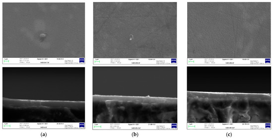
Figure 5.
SEM images of the surfaces of coated Ti-C samples deposited using (a) 20, (b) 25 and (c) 30 sccm of Ar on M42 tool steel substrates.
The potentiostatic corrosion results for the Ti-C coated samples over 1 h of corrosion testing at 0.8 V vs. SHE are shown in Figure 6.
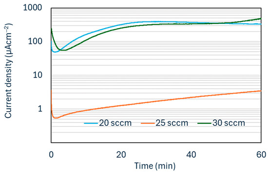
Figure 6.
Potentiostatic corrosion curves for Ti-C coated samples.
Two factors determine the suitability of a coating for corrosion protection of aluminium bipolar plates: the coating being dense and the lack of pinholes and defects, which would expose the substrate surface. A number of studies looking at the use of coatings for aluminium bipolar plates have found defects to be a major contributing factor in the high corrosion rate of coated aluminium plates [28,29]. In these studies, the corrosion current during potentiostatic corrosion testing increases dramatically as a result of these defects. In this work, the coating deposited using an argon flow rate of 25 sccm provided the best corrosion protection, which confirms this coating being dense with a low number of defects. For all subsequent tests, this argon flow was selected during the deposition process.
Figure 7 shows the potentiostatic corrosion test results for a Cr-C coating deposited using 25 sccm of Ar.
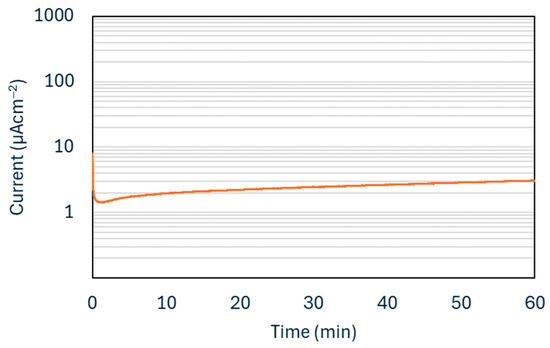
Figure 7.
Potentiostatic corrosion curves for Cr-C coated sample.
Table 1 shows the ICR for the coatings before and after corrosion tests. The pre-corrosion values were similar. However, after corrosion testing, the ICR of the Ti-C coating increased more than that of the Cr-C coating. To establish the reason for this, further post-mortem analysis of the coated plates would be necessary and will be done in future studies. Both coatings had ICR values within the USA Department of Energy requirement of less than 10 mΩ cm2) [10].

Table 1.
ICR of Cr-C and Ti-C coatings before and after corrosion testing.
From a commercial perspective, it would be of great benefit if bipolar plate coatings could be applied prior to the forming of bipolar plates. This would open opportunities for cost saving and production speed, by applying the coating using high-throughput processes, such as roll-to-roll depositions, followed by forming, e.g., by stamping or hydroforming. One major concern with this approach is the possibility of the coating cracking due to the excessive strains applied to it during the forming process. In order to test the effect of strain applied during the forming process on the corrosion protection offered by the coating, potentiostatic corrosion test was performed on samples which had undergone a forming process after coating. The corrosion test results are presented in Figure 8.
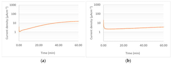
Figure 8.
Potentiostatic corrosion curves for (a) Ti-C coated sample, and (b) Cr-C sample after forming process.
As can be seen, the Cr-C coating showed good corrosion resistance, similar to the result for the coating prior to undergoing the forming process. The coating showed no visible sign of deterioration post-corrosion testing. Müller et al. [30] observed a similar effect in the case of pre-coated and post-coated bipolar plates made from stainless steel 316L. The results obtained from this work are particularly interesting given the extreme susceptibility of aluminium to corrosion if exposed to the reactants.
The Ti-C coatings, however, showed a higher corrosion rate and some areas of the coating showed signs of damage. SEM and EDX analysis were performed on the samples in order to evaluate the coating integrity after forming. Figure 9 summarises the results of this analysis for TiC coating. It is clear that the coating has cracked during forming and that areas of the substrate are exposed, particularly in parts undergoing high strains, i.e., the channel walls. The EDX results confirm the presence of Ti, C, and Ar, as well as a significant amount of Al on the chamber wall, suggesting that the forming process has resulted in the exposure of the aluminium substrate. This can explain the increased corrosion rate for this sample, compared to a sample which had not undergone the forming process. Figure 10 shows the results for the Cr-C coating. In the case of Cr-C, no cracking was observed in the coating, and EDX analysis did not detect exposed aluminium on the surface of the plate. This is in agreement with the corrosion test results for this coating and suggests that the Cr-C coating is less brittle that the Ti-C coating and has been able to endure higher strains without being adversely affected.
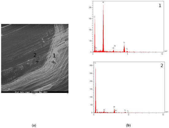
Figure 9.
(a) SEM image of the channel formed on the Ti-C coated aluminium substrate. (b) EDX graphs for the points marked in (a).
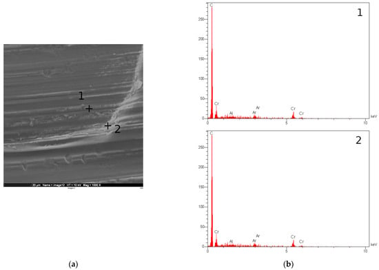
Figure 10.
(a) SEM image of the channel formed on the Cr-C coated aluminium substrate. (b) EDX graphs for the points marked in (a).
Whilst the above results provide vital information regarding the potential of pre-coating bipolar plates, the in situ fuel cell testing in this work was performed by coating pre-machined bipolar plates. Ti-C and Cr-C were applied to aluminium bipolar plates which were used on the cathode side of a single cell with a graphite plate on the anode side. The polarisation curves for cells using these plates as well as a cell using graphite plates on both cathode and anode sides are presented in Figure 11. The aluminium bipolar plate coated with Cr-C showed much less performance drop compared to that coated with Ti-C, which is comparable to the potentiostatic results in Figure 6 and Figure 7. Figure 12 shows the SEM images and elemental composition of the bottom of the gas channel and the top of the ribs. The SEM images confirm that the coating remained on the bipolar plate surface after the test. No coating cracking was observed, as has been reported in the case of ex-situ testing of carbon coatings on aluminium [30]. It was observed that for the Ti-C coating, the surface concentration of carbon coating decreased dramatically with a sharp increase in Al concentration after AST. However, the surface concentrations of C and Al on the Cr-C coated Al plate stayed almost constant before and after the AST. This is also consistent with the EIS results that the Ti-C-coated Al BPP showed a much higher increase in charge transfer resistance compared to the Cr-C-coated Al BPP.
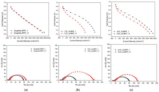
Figure 11.
Polarisation curves and EIS at 0.6 V for single cells based on (a) graphite, (b) Ti-C coated aluminium and (c) Cr-C coated aluminium at the beginning and end of AST tests.
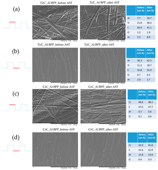
Figure 12.
SEM and EDX analysis results for Ti-C coated aluminium bipolar plates, before and after the AST: (a) land area of Ti-C coated plate, (b) channel area of Ti-C coated plate, (c) land area of Cr-C coated plate, and (d) channel area of Cr-C coated plate.
Overall, the Cr-C coating provided promising results, and although some degradation of its performance was seen after the AST, the performance was better than that of the graphite bipolar plate. It will be important to establish the correlation of the results obtained from the AST protocol in this study with long-term testing of the bipolar plates in order to ascertain the lifetime of the plates in end-use.
4. Conclusions
Carbon coatings with Cr and Ti adhesion layers were evaluated for corrosion protection of bipolar plates based on aluminium alloy 6082. Both coatings provided some corrosion protection for the plates, with the coating with a Cr adhesion layer showing lower corrosion current density under potentiostatic corrosion testing at 0.8 V vs. SHE and 55 °C, as well as a lower degradation rate under AST in a single cell fuel cell. In a test to simulate the stamping of a bipolar plate from an aluminium foil, the coating with a Cr interlayer showed higher resistance to strains experienced and did not crack, whilst the coating with a Ti adhesion layer cracked, exposing the aluminium substrate. Hence, the corrosion performance of the formed plate was better in the case of Cr-C coating. The single cell using an aluminium bipolar plate coated with Cr-C coating on its cathode side provided higher initial performance compared with cells which used a Ti-C-coated plate or graphite. The degradation rate for this cell was lower than the cell employing a Ti-C coated plate but higher than a cell which had graphite on its cathode side.
Author Contributions
Conceptualization, P.N. and H.S.; methodology, P.N., A.E.-K. and L.C.; validation, L.C. and K.Z.; investigation, S.Y., J.Y. and L.C.; resources, H.S. and A.E.-K.; writing, P.N., H.S. and K.Z.; project administration, P.N.; funding acquisition, P.N. All authors have read and agreed to the published version of the manuscript.
Funding
This research was conducted as part of the project HiPerEPC, co-funded by the Innovate UK, project number 80677. The support of Innovate UK is greatly appreciated.
Data Availability Statement
The original contributions presented in the study are included in the article, further inquiries can be directed to the corresponding author.
Conflicts of Interest
P.N., S.Y., J.Y. and H.S. were employed by Teer Coatings Limited. L.C., K.Z. and A.E.-K. declare that the research was conducted in the absence of any commercial or financial relationships that could be construed as a potential conflict of interest.
References
- Steele, B.C.H.; Heinzel, A. Materials for fuel cell technologies. Nature 2001, 414, 345–352. [Google Scholar] [CrossRef] [PubMed]
- Brandon, N.P.; Skinner, S.; Steele, B.C.H. Recent advances in materials for fuel cells. Ann. Rev. Mater. Res. 2003, 33, 183–213. [Google Scholar] [CrossRef]
- Spiegel, C. Designing and Building Fuel Cells; McGraw-Hill: New York, NY, USA, 2007; pp. 35–37, 221–225. [Google Scholar]
- Besmann, T.M.; Klett, J.W.; Henry, J.J.; Lara-Curzio, E. Carbon/Carbon Composite Bipolar Plate for Proton Exchange Membrane Fuel Cells. J. Electrochem. Soc. 2000, 147, 4083–4086. [Google Scholar] [CrossRef]
- González Gutiérrez, A.G.; Sebastian, P.J.; Magallón Cacho, L.; Borja Arco, E.; Campos, J.; Baron, A. Surface Modification of Aluminum Alloy 6061 for Bipolar Plate Application: Adhesion Characteristics and Corrosion Resistance. Int. J. Electrochem. Sci. 2018, 13, 3958–3969. [Google Scholar] [CrossRef]
- González Gutiérrez, A.G.; Pech-Canul, M.A.; Chan-Rosado, G.; Sebastian, P.J. Studies on the physical and electrochemical properties of Ni-P coating on commercial aluminum as bipolar plate in PEMFC. Fuel 2019, 235, 1361–1367. [Google Scholar] [CrossRef]
- Abo El-Enin, S.A.; Abdel-Salam, O.E.; El-Abd, H.; Amin, A.M. New electroplated aluminum bipolar plate for PEM fuel cell. J. Power. Sources 2008, 177, 131–136. [Google Scholar] [CrossRef]
- Fetohi, A.E.; Abdel Hamed, R.M.; El-Khatib, K.M.; Souaya, E.R. Ni–P and Ni–Co–P coated aluminum alloy 5251 substrates as metallic bipolar plates for PEM fuel cell applications. Int. J. Hydrogen Energy 2012, 37, 7677–7688. [Google Scholar] [CrossRef]
- Madadi, F.; Rezaeian, A.; Edris, H.; Zhiani, M. Improving performance in PEMFC by applying different coatings to metallic bipolar plates. Meter. Chem. Phys. 2019, 238, 121911. [Google Scholar] [CrossRef]
- DOE Technical Targets for Polymer Electrolyte Membrane Fuel Cell Components. Available online: https://www.energy.gov/eere/fuelcells/doe-technical-targets-polymer-electrolyte-membrane-fuel-cell-components (accessed on 8 July 2024).
- Hung, Y.; Tawfik, H.; Mahajan, D. Durability and characterization studies of chromium carbide coated aluminum fuel cell stack. Int. J. Hydrogen Energy 2016, 41, 12273–12284. [Google Scholar] [CrossRef]
- Lee, S.-J.; Huang, C.-H.; Chen, Y.-P.; Chen, Y.-M. Chemical Treatment Method for the Aluminum Bipolar Plates of PEM Fuel Cells. J. Fuel Cell Sci. Technol. 2005, 2, 208–215. [Google Scholar] [CrossRef]
- Lee, C.-H.; Lee, Y.-B.; Kim, K.-M.; Jeong, M.-G.; Lim, D. Soon, Electrically conductive polymer composite coating on aluminum for PEM fuel cells bipolar plate. Renew. Energy 2013, 54, 46–50. [Google Scholar] [CrossRef]
- Madwsley, J.R.; Carter, J.D.; Wang, X.; Niyogi, S.; Fan, C.Q.; Koc, R.; Osterhout, G. Composite-coated aluminum bipolar plates for PEM fuel cells. J. Power Sources 2013, 231, 106–112. [Google Scholar] [CrossRef]
- Lee, S.-J.; Huang, C.-H.; Chen, Y.-P. Investigation of PVD coating on corrosion resistance of metallic bipolar plates in PEM fuel cell. J. Mater. Process. Technol. 2003, 140, 688–693. [Google Scholar] [CrossRef]
- Narasimharaju, S.; Rao, B.P.C.; Annamalai, K. Advancements in Multilayer Coatings on Aluminium Alloy-Based Bipolar Plates for PEMFC Application. Int. Res. J. Adv. Eng. Hub 2024, 2, 190–204. [Google Scholar] [CrossRef]
- Feng, K.; Shen, Y.; Sun, H.; Liu, D.; An, Q.; Cai, X.; Chu, P.K. Conductive amorphous carbon-coated 316L stainless steel as bipolar plates in polymer electrolyte membrane fuel cells. Int. J. Hydrogen Energy 2009, 34, 6771–6777. [Google Scholar] [CrossRef]
- Pukha, V.E.; Glukhov, A.A.; Belmesov, A.A.; Kabachov, E.N.; Khodos, I.I.; Khadem, M.; Kim, D.-E.; Karaseov, P.A. Corrosion-resistant nanostructured carbon-based coatings for applications in fuel cells based on bipolar plates. Vacuum 2023, 218, 112643. [Google Scholar] [CrossRef]
- Liu, R.; Jia, Q.; Zhang, B.; Lai, Z.; Chen, L. Protective coatings for metal bipolar plates of fuel cells: A review. Int. J. Hydrogen Energy 2022, 47, 22915–22937. [Google Scholar] [CrossRef]
- Gorman, D.; Green, C.; Booth-Downs, F.; Gee, M.; Fry, T. Rockwell Indentation Test for Evaluation of Adhesion of Coatings—Aka Daimler-Benz adhesion test. NPL Report. MAT 107; NPL: London, UK, 2022. [Google Scholar]
- Yi, R.; Zhang, D.; Qiu, D.; Peng, L.; Lai, X. Carbon-based coatings for metallic bipolar plates used in proton exchange membrane fuel cells. Int. J. Hydrogen Energy 2019, 44, 6813–6843. [Google Scholar] [CrossRef]
- Bi, F.; Hou, K.; Yi, P.; Peng, L.; Lai, X. Mechanisms of growth, properties and degradation of amorphous carbon films by closed field unbalanced magnetron sputtering on stainless steel bipolar plates for PEMFCs. Appl. Surf. Sci. 2017, 422, 921–931. [Google Scholar] [CrossRef]
- Bi, F.; Li, X.; Yi, P.; Hou, K.; Peng, L.; Lai, X. Characteristics of amorphous carbon films to resist high potential impact in PEMFCs bipolar plates for automotive application. Int. J. Hydrogen Energy 2017, 42, 14279–14289. [Google Scholar] [CrossRef]
- Sun, H.; Cooke, K.; Eitzinger, G.; Hamilton, P.; Pollet, B. Development of PVD coatings for PEMFC bipolar plates. Thin Solid Film. 2013, 528, 199–204. [Google Scholar] [CrossRef]
- Kulikovsky, V.; Bohac, P.; Franc, F.; Deineka, A.; Vorlicek, V.; Jastrabik, L. Hardness, intrinsic stress, and structure of the a-C and a-C:H films prepared by magnetron sputtering. Diam. Relat. Mater. 2001, 10, 1076–1081. [Google Scholar] [CrossRef]
- Steinhorst, M.; Giorgio, M.; Roch, T.; Leyens, C. Effect of Process Pressure on Carbon-Based Thin Films Deposited by Cathodic Arc on Stainless Steel for Bipolar Plates. Coatings 2023, 13, 1962. [Google Scholar] [CrossRef]
- Yi, P.; Zhang, W.; Bi, F.; Peng, L.; Lai, X. Microstructure and properties of a-C films deposited under different argon flow rate on stainless steel bipolar plates for proton exchange membrane fuel cells. J. Power Sources 2019, 410–411, 188–195. [Google Scholar] [CrossRef]
- Dabiri Havigh, M.; Hubin, A.; Terryn, H. Assessment of Carbon-Titanium Multilayer Coatings on Aluminum as Bipolar Plates in PEM Fuel Cells. J. Electrochem. Soc. 2021, 168, 061503. [Google Scholar] [CrossRef]
- Li, Z.; Feng, K.; Wang, Z.; Cai, X.; Yao, C.; Wu, Y. Investigation of single-layer and multilayer coatings for aluminium bipolar plate in polymer electrolyte membrane fuel cell. Int. J. Hydrogen Energy 2014, 27, 8421–8430. [Google Scholar] [CrossRef]
- Müller, M.-V.; Giorgio, M.; Hausmann, P.; Kinlechner, L.; Heinzel, A.; Schwämmlein, J. Investigation of the effect of carbon post- vs pre-coated metallic bipolar plates for PEMFCs—Start-up and shut-down. Int. J. Hydrogen Energy 2022, 47, 8532–8548. [Google Scholar] [CrossRef]
Disclaimer/Publisher’s Note: The statements, opinions and data contained in all publications are solely those of the individual author(s) and contributor(s) and not of MDPI and/or the editor(s). MDPI and/or the editor(s) disclaim responsibility for any injury to people or property resulting from any ideas, methods, instructions or products referred to in the content. |
© 2024 by the authors. Licensee MDPI, Basel, Switzerland. This article is an open access article distributed under the terms and conditions of the Creative Commons Attribution (CC BY) license (https://creativecommons.org/licenses/by/4.0/).