Impact of Corrosion in Simulated Body Fluid on Fatigue Characteristics of 3D-Printed Polylactic Acid-Coated AM60 Magnesium Alloys


Abstract
1. Introduction
2. Materials and Methods
2.1. Materials and Manufacturing Method
2.2. Corrosion Test
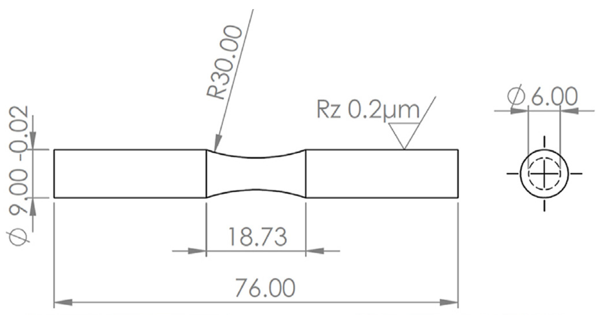
2.3. Fatigue Test
2.4. Fracture Surface Analysis
3. Results and Discussion
4. Conclusions
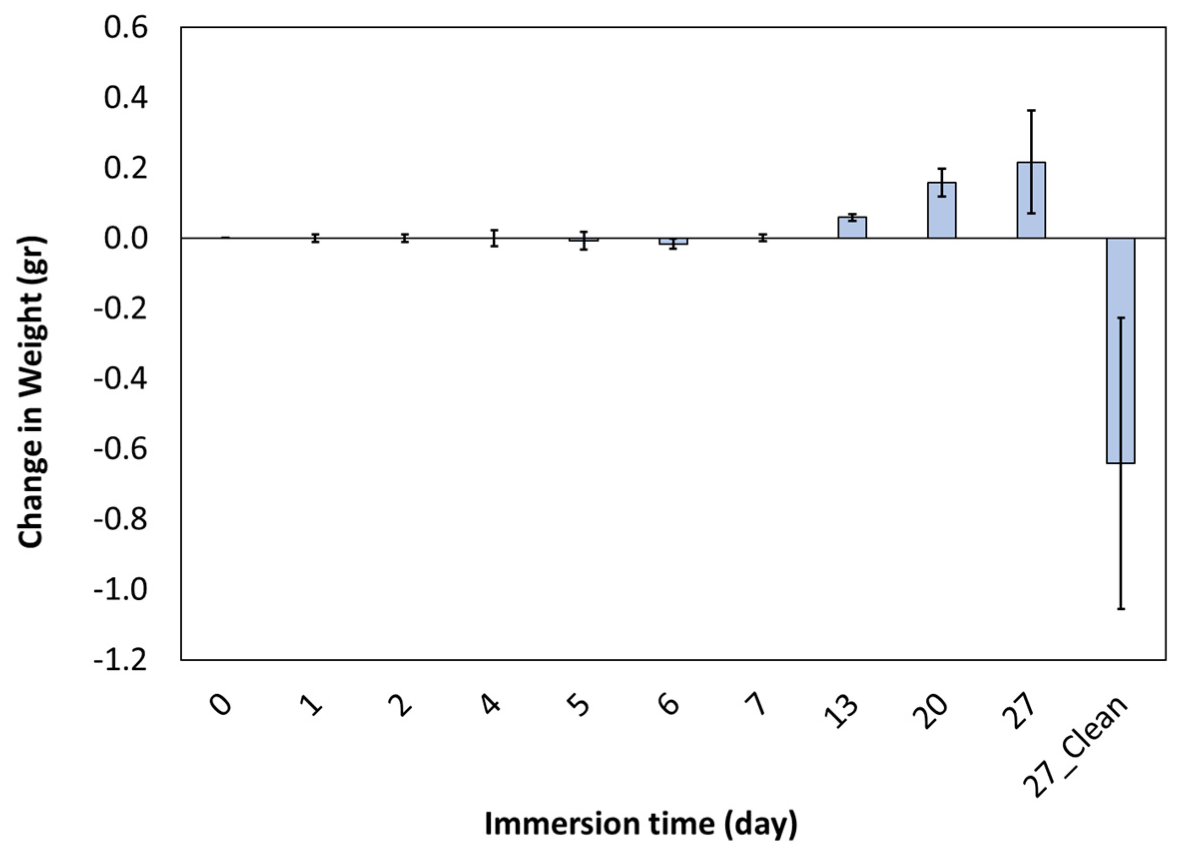
- Due to corrosion, the weight of the sample decreased by 35%.
- The corrosion rate decreased in the first seven days and then increased.
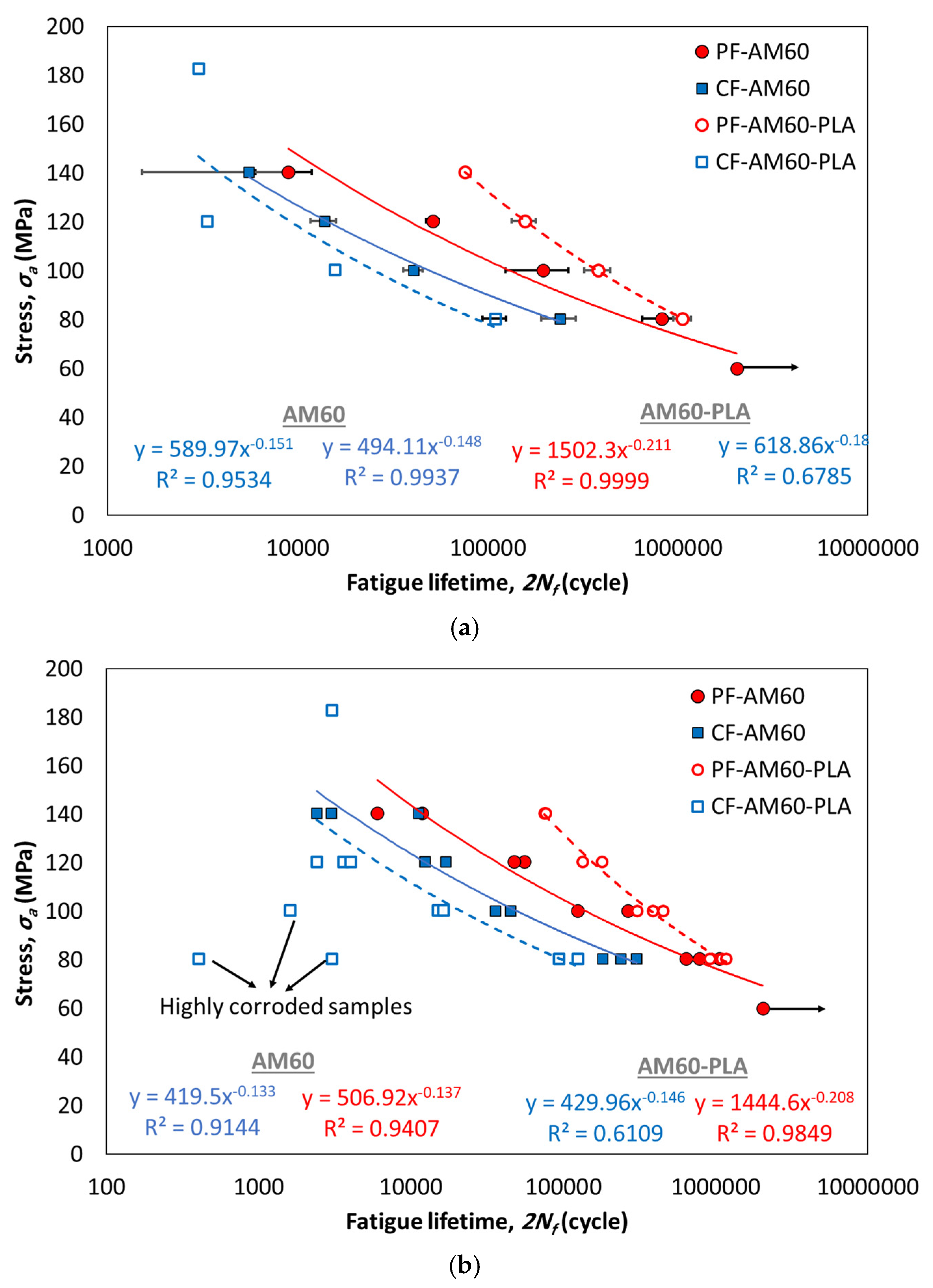
- Compared to the PF-AM60 sample, the PF-AM60-PLA specimen on average had a 49% increase in fatigue lifetime.
- Despite using a 10-times stronger solution, the fatigue lifetime of CF-AM60-PLA specimens is reduced by only 35% compared to CF-AM60 samples.
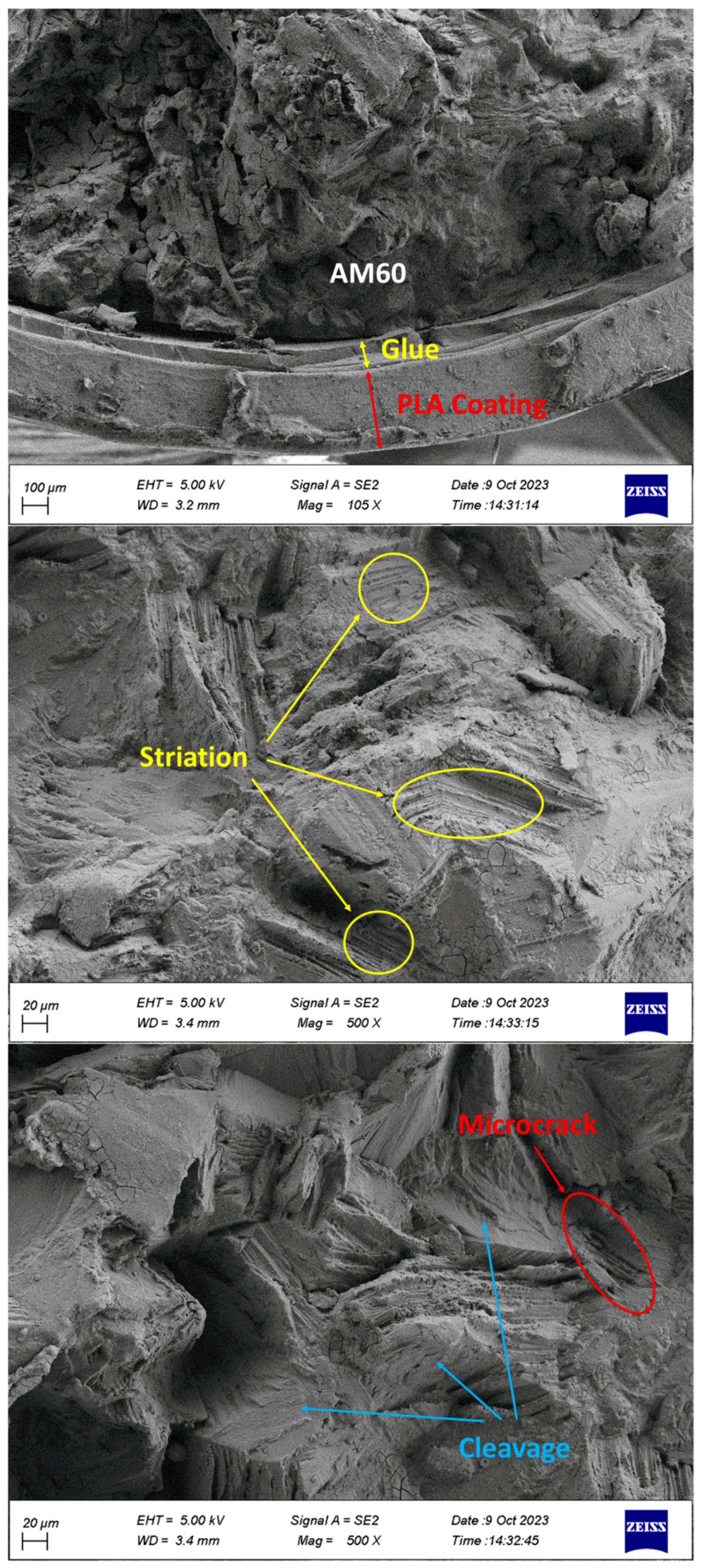
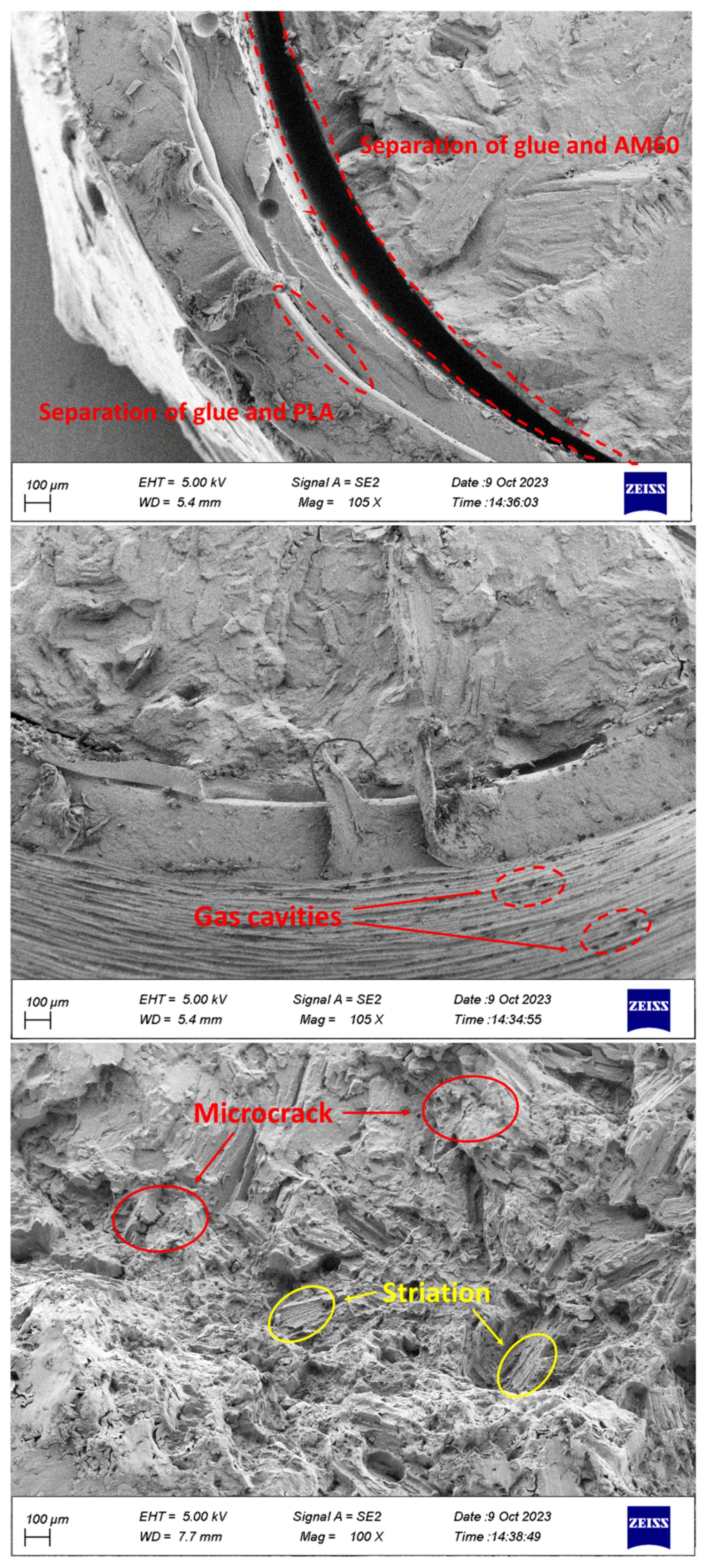
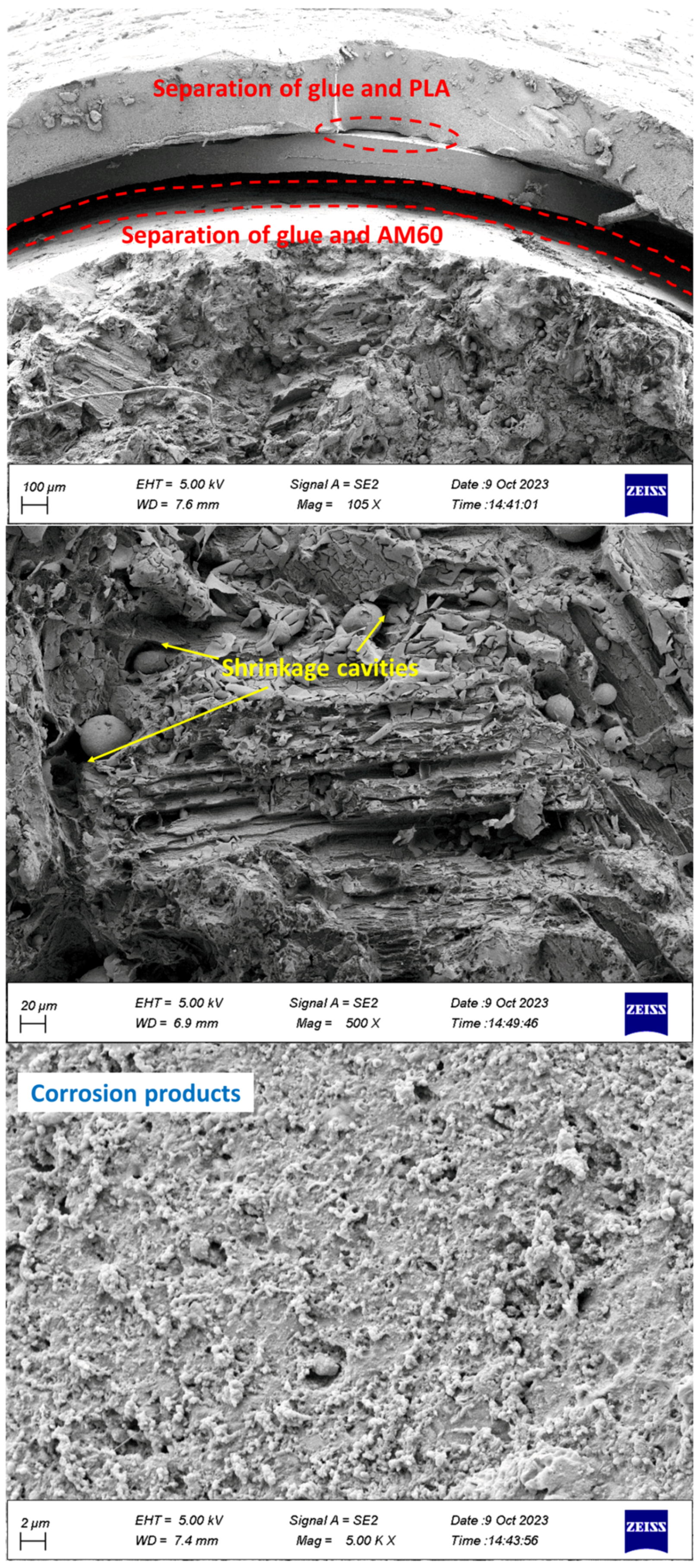
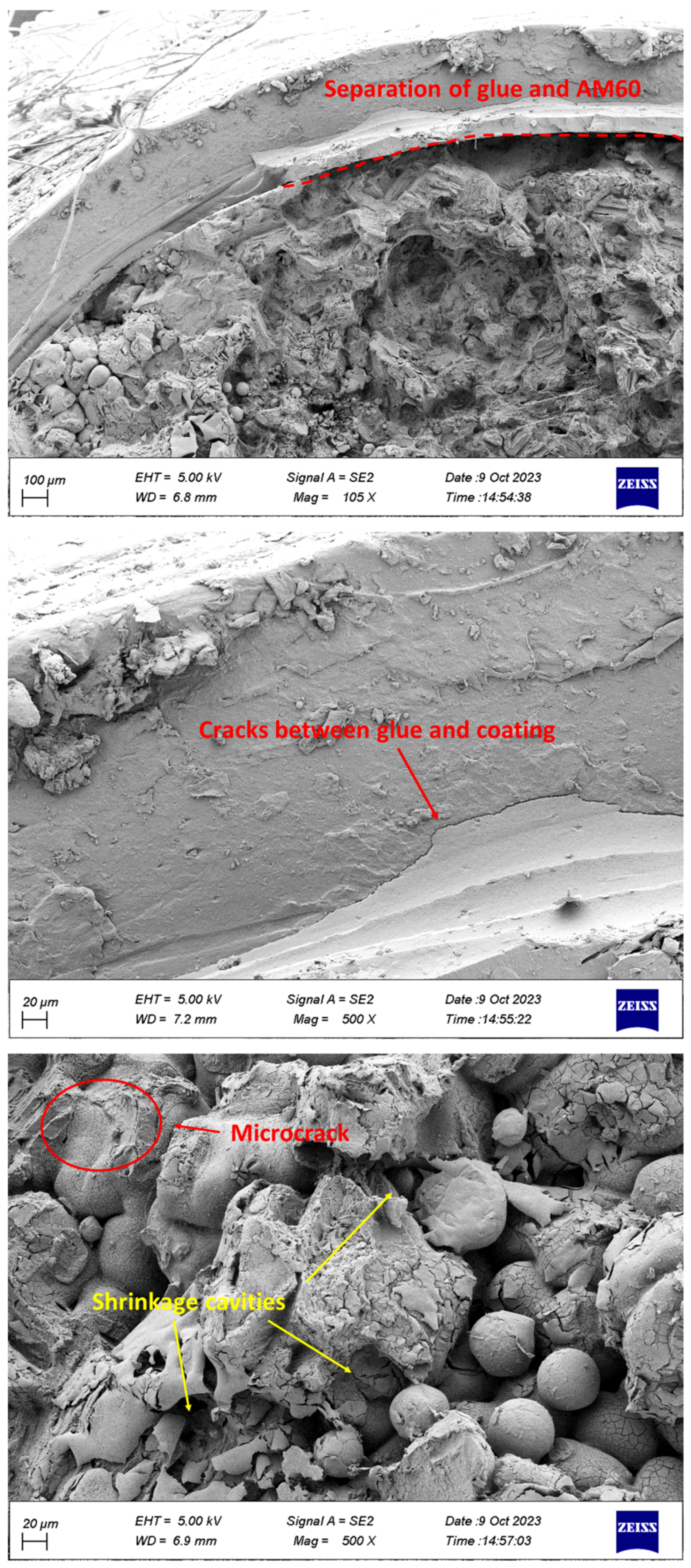
- The separation of coating from glue and glue from Mg was observed in the specimens.
- Cleavage plates caused by brittle fractures and striations during fatigue load were seen on the failure surface.
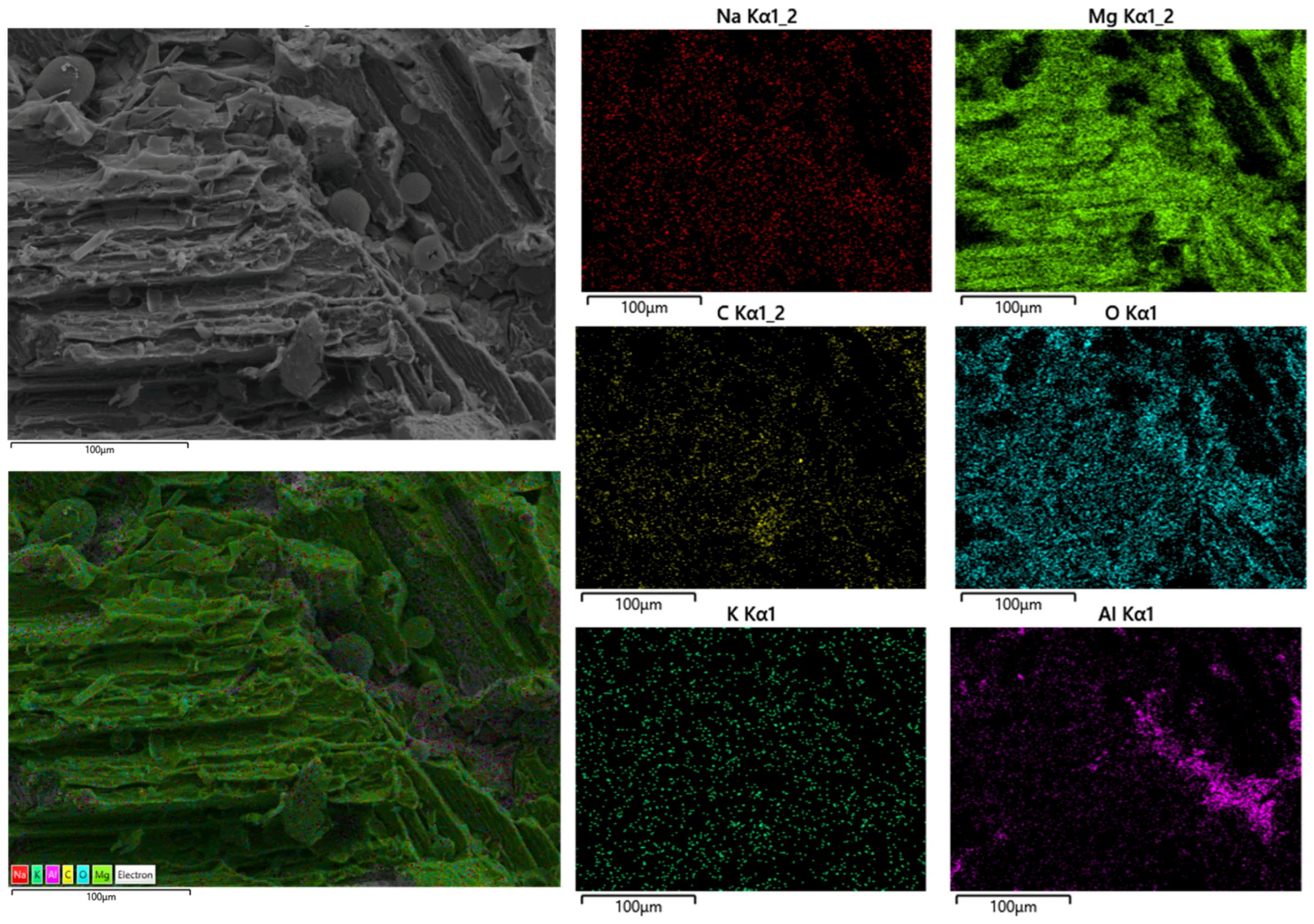
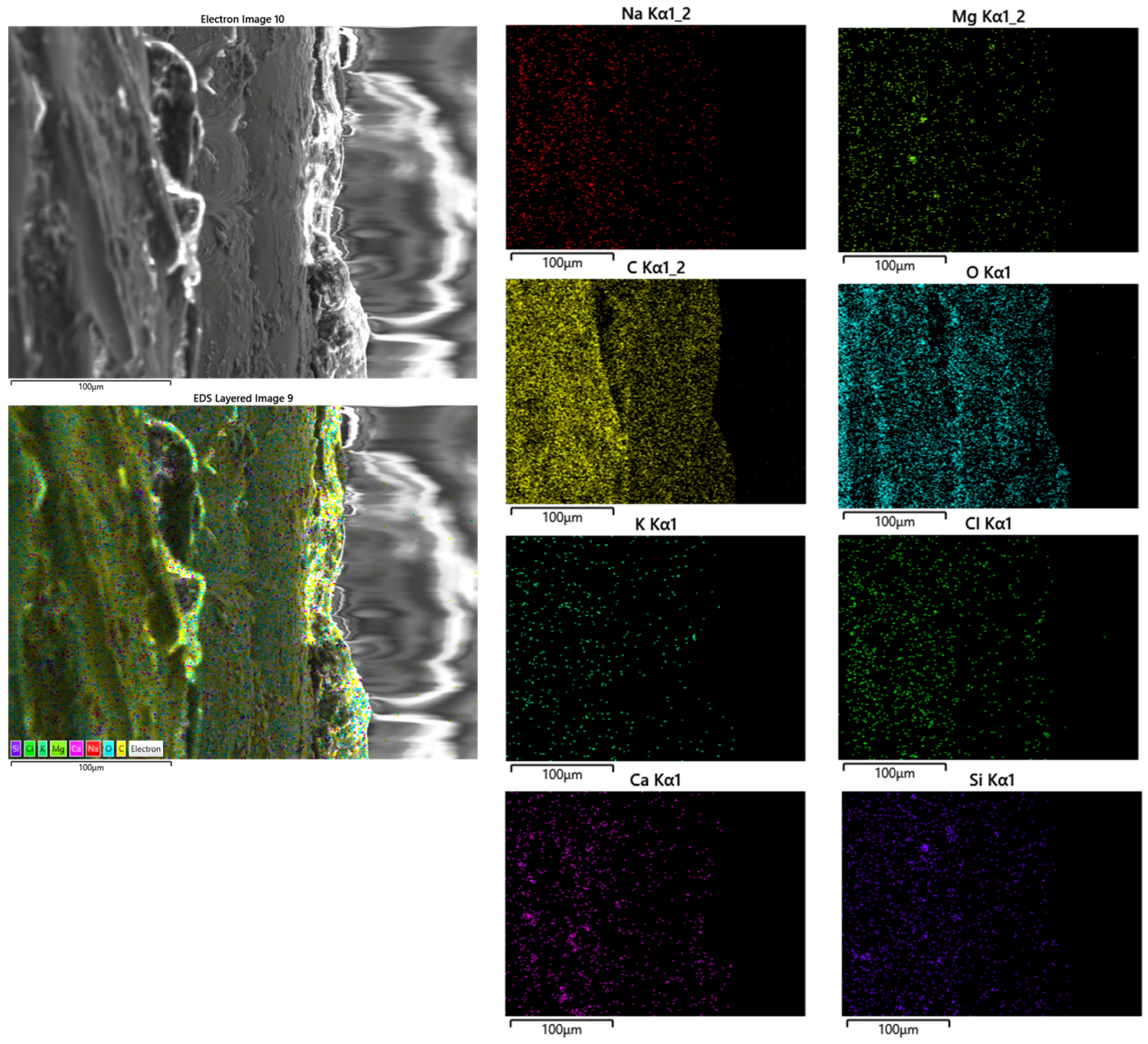
- Corrosion products, including microcracks and holes, were seen on the fracture surfaces of CF samples, which caused stress concentration and crack growth.
- Holes caused by the release of gases were observed in the PLA coating layers, which were fabricated by 3D printing.
Author Contributions
Funding
Data Availability Statement
Conflicts of Interest
References
- Wu, C.S.; Zhang, Z.; Cao, F.H.; Zhang, L.J.; Zhang, J.Q.; Cao, C.N. Study on the anodizing of AZ31 magnesium alloys in alkaline borate solutions. Appl. Surf. Sci. 2007, 253, 3893–3898. [Google Scholar] [CrossRef]
- Moosbrugger, C. Engineering Properties of Magnesium Alloys; ASM International: Materials Park, OH, USA, 2017. [Google Scholar]
- Zartner, P.; Cesnjevar, R.; Singer, H.; Weyand, M. First successful implantation of a bio-degradable metal stent into the left pulmonary artery of a preterm baby. Catheter Cardiovasc. Interv. 2005, 66, 590–594. [Google Scholar] [CrossRef]
- Heublein, B.; Rohde, R.; Kaese, V.; Niemeyer, M.; Hartung, W.; Haverich, A. Bio-corrosion of magnesium alloys: A new principle in cardiovascular implant technology. Heart 2003, 89, 651–656. [Google Scholar] [CrossRef]
- Baril, G.; Blanc, C.; Pebere, N. AC impedance spectroscopy in characterizing time-dependent corrosion of AZ91 and AM50 magnesium alloys characterization with respect to their microstructures. J. Electrochem. Soc. 2001, 148, B489. [Google Scholar] [CrossRef]
- Staiger, M.P.; Pietak, A.M.; Huadmai, J.; Dias, G. Magnesium and its alloys as orthopedic biomaterials: A review. Biomaterials 2006, 27, 1728–1734. [Google Scholar] [CrossRef] [PubMed]
- Song, Y.; Liu, D.; Tang, W.; Dong, K.; Shan, D.; Han, E. Comparison of the corrosion behavior of AM60 Mg alloy with and without self-healing coating in atmospheric environment. J. Magnes. Alloys 2021, 9, 1220–1232. [Google Scholar] [CrossRef]
- Liu, W.; Cao, F.; Jia, B.; Zheng, L.; Zhang, J.; Cao, C.; Li, X. Corrosion behavior of AM60 magnesium alloys containing Ce or La under thin electrolyte layers. Part 2: Corrosion product and characterization. Corros. Sci. 2010, 52, 639–650. [Google Scholar] [CrossRef]
- Matsubara, H.; Ichige, Y.; Fujita, K.; Nishiyama, H.; Hodouchi, K. Effect of impurity Fe on corrosion behavior of AM50 and AM60 magnesium alloys. Corros. Sci. 2013, 66, 203–210. [Google Scholar] [CrossRef]
- Xie, Z.; Luo, Z.; Yang, Q.; Chen, T.; Tan, S.; Wang, Y.; Luo, Y. Improving anti-wear and anti-corrosion properties of AM60 magnesium alloy by ion implantation and Al/AlN/CrAlN/CrN/MoS2 gradient duplex coating. Vacuum 2014, 101, 171–176. [Google Scholar] [CrossRef]
- Kumar, D. Effect of hydroxyapatite (HA) addition on microstructure, corrosion resistance of AZ91D, AJ62 and AM60 alloys. Mater. Today Proc. 2022, 50, 582–584. [Google Scholar] [CrossRef]
- Chenghao, L.; Shusen, W.; Naibao, H.; Zhihong, Z.; Shuchun, Z.; Jing, R. Effects of lanthanum and cerium mixed rare earth metal on abrasion and corrosion resistance of AM60 magnesium alloy. Rare Met. Mater. Eng. 2015, 44, 521–526. [Google Scholar] [CrossRef]
- Ikpi, M.E.; Dong, J.; Ke, W. Electrochemical Investigation of the Galvanic Corrosion of AM60 and AD62 Magnesium Alloy in 0.1 M NaCl Solution Magdalene. Int. J. Electrochem. Sci. 2015, 10, 552–563. [Google Scholar] [CrossRef]
- Liu, D.; Song, Y.; Shan, D.; Han, E. Comparison of the inhibition effect of four inhibitors on the corrosion behavior of AM60 magnesium alloy. Int. J. Electrochem. Sci. 2019, 13, 2219–2235. [Google Scholar] [CrossRef]
- Jin-Ling, Z.; Yang-Li, L.; Jing, Z.; Zhi-Yong, F.; She-Bin, W. Kinetic study on the corrosion behavior of AM60 magnesium alloy with different Nd contents. J. Alloys Compd. 2015, 629, 290–296. [Google Scholar] [CrossRef]
- Akbaripanah, F.; Fereshteh-Saniee, F.; Mahmudi, R.; Kim, H.K. The influences of extrusion and equal channel angular pressing (ECAP) processes on the fatigue behavior of AM60 magnesium alloy. Mater. Sci. Eng. A 2013, 565, 308–316. [Google Scholar] [CrossRef]
- Khan, S.A.; Miyashita, Y.; Mutoh, Y.; Koike, T. Fatigue behavior of anodized AM60 magnesium alloy under humid environment. Mater. Sci. Eng. A 2008, 498, 377–383. [Google Scholar] [CrossRef]
- Hiromoto, S.; Tomozawa, M.; Maruyama, N. Fatigue property of a bioabsorbable magnesium alloy with a hydroxyapatite coating formed by a chemical solution deposition. J. Mech. Behav. Biomed. Mater. 2013, 25, 1–10. [Google Scholar] [CrossRef]
- Singh Raman, R.K.; Jafari, S.; Harandi, S.E. Corrosion fatigue fracture of magnesium alloys in bioimplant applications: A review. Eng. Fract. Mech. 2015, 137, 97–108. [Google Scholar] [CrossRef]
- Uematsu, Y.; Kakiuchi, T.; Teratani, T.; Harada, Y.; Tokaji, K. Improvement of corrosion fatigue strength of magnesium alloy by multilayer diamond-like carbon coatings, Improvement of corrosion fatigue strength of magnesium alloy by multilayer diamond-like carbon coatings. Surf. Coat. Technol. 2011, 205, 2778–2784. [Google Scholar] [CrossRef]
- AlamKhan, S.; Bhuiyan, M.S.; Miyashita, Y.; Mutoh, Y.; Koike, T. Corrosion fatigue behavior of die-cast and shot-blasted AM60 magnesium alloy. Mater. Sci. Eng. A 2011, 528, 1961–1966. [Google Scholar] [CrossRef]
- Ishihara, S.; Namito, T.; Notoya, H.; Okada, A. The corrosion fatigue resistance of an electrolytically-plated magnesium alloy. Int. J. Fatigue 2010, 32, 1299–1305. [Google Scholar] [CrossRef]
- Talesh, S.A.A.; Azadi, M. High-cycle fatigue testing on AM60 magnesium alloy samples for as-received and pre-corroded conditions in simulated body fluid. J. Mater. Res. Technol. 2023, 27, 1922–1934. [Google Scholar] [CrossRef]
- Antunes, R.A.; De Oliveira, M.C.L. Corrosion fatigue of biomedical metallic alloys: Mechanisms and mitigation. Acta Biomater. 2012, 8, 937–962. [Google Scholar] [CrossRef] [PubMed]
- Delavar, H.; Mostahsan, A.J.; Ibrahim, H. Corrosion and corrosion-fatigue behavior of magnesium metal matrix composites for bio-implant applications: A review. J. Magnes. Alloys 2023, 11, 1125–1161. [Google Scholar] [CrossRef]
- Shi, Y.; Yang, L.; Zhang, Q.; Zhu, X.; Song, Z.; Liu, H. A novel MAO-PLA coating on zinc alloy for potential orthopedic implant material. Mater. Lett. 2022, 317, 132058. [Google Scholar] [CrossRef]
- Anand, N.; Pal, K. Evaluation of biodegradable Zn-1Mg-1Mn and Zn-1Mg-1Mn-1HA composites with a polymer-ceramics coating of PLA/HA/TiO2 for orthopaedic applications. J. Mech. Behav. Biomed. Mater. 2022, 136, 105470. [Google Scholar] [CrossRef]
- Wang, A.; Venezuela, J.; Dargusch, M.S. Enhancing the corrodibility of biodegradable iron and zinc using poly (lactic) acid (PLA) coating for temporary medical implant applications. Prog. Org. Coat. J. 2023, 174, 107301. [Google Scholar] [CrossRef]
- Beyzavi, A.H.; Azadi, M.; Azadi, M.; Dezianian, S.; Talebsafa, V. Bio-polymer coatings fabricated on AM60 magnesium alloys by fused deposition modeling 3D-printing to investigate electrochemical behavior. Mater. Lett. 2023, 337, 133935. [Google Scholar] [CrossRef]
- Rezanezhad, S.; Azadi, M. Amazing epsilon-shaped trend for fretting fatigue characteristics in AM60 magnesium alloy under stress-controlled cyclic conditions at bending loads with zero mean stress. PLoS ONE 2023, 18, 0281263. [Google Scholar] [CrossRef]
- Dezianian, S.; Azadi, M. Multi-material metamaterial topology optimization to minimize the compliance and the constraint of weight: Application of non-pneumatic tire additive-manufactured with PLA/TPU polymers. Polymers 2023, 15, 1927. [Google Scholar] [CrossRef]
- Dezianian, S.; Azadi, M.; Razavi, S.M.J. Topology optimization on metamaterial cells for replacement possibility in non-pneumatic tire and the capability of 3D-printing. PLoS ONE 2023, 18, e0290345. [Google Scholar] [CrossRef] [PubMed]
- Rezanezhad, S.; Azadi, M. Impact of 3D-printed PLA coatings on the mechanical and adhesion properties of AM60 magnesium alloys. Compos. Part C 2023, 12, 100415. [Google Scholar] [CrossRef]
- Azadi, M.; Dadashi, A.; Dezianian, S.; Kianifar, M.; Torkaman, S.; Chiyani, M. High-cycle bending fatigue properties of additive-manufactured ABS and PLA polymers fabricated by fused deposition modeling 3D-printing. Forces Mech. 2021, 3, 100016. [Google Scholar] [CrossRef]
- Rudawska, A.; Sarna-Bos, K.; Rudawska, A.; Rozylo-Kalinowska, I.; Chalas, R. Biological and chemical properties of cured epoxy resins. Res. Sq. 2021. [Google Scholar] [CrossRef]
- Munoz, M.; Torres, B.; Mohedano, M.; Matykina, E.; Arrabal, R.; Lopez, A.J.; Rams, J. PLA deposition on surface treated magnesium alloy: Adhesion, toughness and corrosion behavior. Surf. Coat. Technol. 2020, 388, 125593. [Google Scholar] [CrossRef]
- Simulated Body Fluid Catalog; Pardis Pajouhesh Fanavaran Yazd Company, Yazd Science and Technology Park: Yazd, Iran, 2023.
- ASTM G31-72; Standard Practice for Laboratory Immersion Corrosion Testing of Metals. ASTM International: West Conshohocken, PA, USA, 2004.
- ISO 1143:2010; Metallic Materials—Rotating Bar Bending Fatigue Testing. International Organization for Standardization: Geneva, Switzerland, 2010.
- DIN EN 50113; Rotating Bar Bending Fatigue Test. DIN Standard: Berlin, Germany, 1982.
- Oliya, A.Y.P.; Azadi, M.; Parast, M.S.A.; Mokhtarishirazabad, M. Effect of heat-treating on microstructure and high cycle bending fatigue behavior of AZ91 and AZE911 magnesium alloys. Adv. Mater. Sci. Eng. 2022, 2022, 4030062. [Google Scholar] [CrossRef]
- Hodaeian, H. Degradation of Pure Magnesium Alloys in Simulated Body Fluid. Master’s Thesis, University of Birmingham, Birmingham, UK, 2013. [Google Scholar]
- Guo, Z.; Yang, C.; Zhou, Z.; Chen, S.; Li, F. Characterization of biodegradable poly (lactic acid) porous scaffolds prepared using selective enzymatic degradation for tissue engineering. R. Soc. Chem. Adv. 2017, 7, 34063. [Google Scholar] [CrossRef]
- Hasanpur, E.; Ghazavizadeh, A.; Sadeghi, A.; Haboussi, M. In vitro corrosion study of PLA/Mg composites for cardiovascular stent applications. J. Mech. Behav. Biomed. Mater. 2021, 124, 104768. [Google Scholar] [CrossRef]
- Balogova, A.; Trebunova, M.; Izarikova, G.; Kascak, L.; Mitrik, L.; Klimova, J.; Feranc, J.; Modrak, M.; Hudak, R.; Zivcak, J. In vitro degradation of specimens produced from PLA/PHB by additive manufacturing in simulated conditions. Polymers 2021, 13, 1542. [Google Scholar] [CrossRef]
- Redondo, F.; Giaroli, M.; Ciolino, A.; Ninago, M. Preparation of Porous Poly (Lactic Acid)/Tricalcium Phosphate Composite Scaffolds for Tissue Engineering. Biointerface Res. Appl. Chem. 2022, 12, 5610–5624. [Google Scholar]
- Alksne, M.; Kalvaityte, M.; Simoliunas, E.; Rinkunaite, I.; Gendviliene, I.; Locs, J.; Rutkunas, V.; Bukelskiene, V. In vitro comparison of 3D printed polylactic acid/hydroxyapatite and polylactic acid/bio-glass composite scaffolds: Insights into materials for bone regeneration. J. Mech. Behav. Biomed. Mater. 2020, 104, 103641. [Google Scholar] [CrossRef]
- Chor, A.; Gonçalves, R.; Costa, A.; Farina, M.; Ponche, A.; Sirelli, L.; Schrodj, G.; Gree, S.; Andrade, L.; Anselme, K.; et al. In vitro degradation of electro-spun poly (lactic-Co-glycolic acid) (PLGA) for oral mucosa regeneration. Polymers 2020, 12, 1853. [Google Scholar] [CrossRef]
- Voicu, M.E.; Demetrescu, I.; Dorobantu, A.; Enachescu, M.; Buica, G.O.; Ionita, D. Interaction of Mg alloy with PLA electro-spun nanofibers coating in understanding changes of corrosion. Nanomaterials 2022, 12, 12081369. [Google Scholar] [CrossRef]
- Shi, P.; Niu, B.; Shanshan, E.; Chen, Y.; Li, Q. Preparation and characterization of PLA coating and PLA/MAO composite coatings on AZ31 magnesium alloy for improvement of corrosion resistance. Surf. Coat. Technol. 2015, 262, 26–32. [Google Scholar] [CrossRef]
- Basquin, O.H. The exponential law of endurance tests. Proc. Am. Soc. Test. Mater. 1910, 10, 625–630. [Google Scholar]
- Nan, Z.Y.; Ishihara, S.; Goshima, T. Corrosion fatigue behavior of extruded magnesium alloy AZ31 in sodium chloride solution. Int. J. Fatigue 2008, 30, 1181–1188. [Google Scholar] [CrossRef]
- Bhuiyan, M.S.; Mutoh, Y.; Murai, T.; Iwakami, S. Corrosion fatigue behavior of extruded magnesium alloy AZ61 under three different corrosive environments. Int. J. Fatigue 2008, 30, 1756–1765. [Google Scholar] [CrossRef]
- Parast, M.S.A.; Azadi, M. A short evaluation of simultaneous corrosion fretting fatigue behaviors in piston aluminum-silicon alloys considering effects of nano-particles and heat-treating. Int. J. Fatigue 2023, 168, 107403. [Google Scholar] [CrossRef]
- Stephens, R.; Fatemi, A.; Stephens, R.; Fuchs, H. Metal Fatigue in Engineering; John Wiley and Sons: Hoboken, NJ, USA, 2000. [Google Scholar]
- Ghazizadeh, E.; Jabbari, A.H.; Sedighi, M. In vitro corrosion fatigue behavior of biodegradable Mg/HA composite in simulated body fluid. J. Magnes. Alloys 2021, 9, 2169–2184. [Google Scholar] [CrossRef]
- Mokhtarishirazabad, M.; Azadi, M.; Farrahi, G.H.; Winter, G.; Eichlseder, W. Improvement of high temperature fatigue lifetime in AZ91 magnesium alloy by heat treatment. Mater. Sci. Eng. A 2013, 588, 357–365. [Google Scholar] [CrossRef]
- Jiang, L.; Xu, F.; Xu, Z.; Chen, Y.; Zhou, X.; Wei, G.; Ge, H. Biodegradation of AZ31 and WE43 magnesium alloys in simulated body fluid. Int. J. Electrochem. Sci. 2015, 10, 10422–10432. [Google Scholar] [CrossRef]
- Kuznetsov, V.E.; Solonin, A.N.; Urzhumtsev, O.D.; Schilling, R.; Tavitov, A.G. Strength of PLA components fabricated with fused deposition technology using a desktop 3D printer as a function of geometrical parameters of the process. Polymers 2018, 10, 313. [Google Scholar] [CrossRef]
- Gonabadi, H.; Yadav, A.; Bull, S.J. The effect of processing parameters on the mechanical characteristics of PLA produced by a 3D FFF printer. Int. J. Adv. Manuf. Technol. 2020, 111, 695–709. [Google Scholar] [CrossRef]
- Liu, M.; Wang, J.; Zhu, S.; Zhang, Y.; Sun, Y.; Wang, L.; Guan, S. Corrosion fatigue of the extruded Mg-Zn-Y-Nd alloy in simulated body fluid. J. Magnes. Alloys 2020, 8, 231–240. [Google Scholar] [CrossRef]
- Hu, H.; Zhou, M.; Sun, Z.; Li, N. Tensile behavior and fracture characteristics of die cast magnesium alloy AM50. J. Mater. Process. Technol. 2008, 201, 364–368. [Google Scholar] [CrossRef]
- Chen, Q.; Zhao, Z.; Chen, G.; Wang, B. Effect of accumulative plastic deformation on generation of spheroidal structure, thixoformability and mechanical properties of large-size AM60 magnesium alloy. J. Alloys Compd. 2015, 632, 190–200. [Google Scholar] [CrossRef]
- Bhuiyan, M.S.; Mutoh, Y.; Murai, T.; Iwakami, S. Corrosion fatigue behavior of extruded magnesium alloy AZ80-T5 in a 5% NaCl environment. Eng. Fract. Mech. 2010, 77, 1567–1576. [Google Scholar] [CrossRef]
- Barzegari, M.; Mei, D.; Lamaka, S.V.; Geris, L. Computational modeling of degradation process of biodegradable magnesium biomaterials. Corros. Sci. 2021, 190, 109674. [Google Scholar] [CrossRef]
- Mei, D.; Lamaka, S.V.; Lu, X.; Zheludkevich, M.L. Selecting medium for corrosion testing of bioabsorbable magnesium and other metals—A critical review. Corros. Sci. 2020, 171, 108722. [Google Scholar] [CrossRef]


| Mg | Mn | Zn | Si | Al | Ni | Cu |
|---|---|---|---|---|---|---|
| Bulk | 0.3 | 0.07 | 0.04 | 5.5 | 0.004 | 0.01 |
| Parameters | Speed (mm/s) | Nozzle Temperature (°C) | Bed Temperature (°C) | Infill in the First and Last Layer (%) | Infill in the Inner Layer (%) | Layer Height (µm) | Nozzle Diameter (mm) |
|---|---|---|---|---|---|---|---|
| Value | 50 | 245 | 60 | 100 | 50 | 50 | 0.4 |
| Ions | Concentration (mM) | Ions | Concentration (mM) |
|---|---|---|---|
| Mg2+ | 15.0 | HPO42− | 10.0 |
| K+ | 50.0 | HCO3− | 42.0 |
| Na+ | 1420.0 | Cl− | 1478.0 |
| Ca2+ | 25.0 | SO42− | 5.0 |
| Test Conditions | All Data | Average Data | ||||
|---|---|---|---|---|---|---|
| (MPa) | b | R2 | b | R2 | ||
| PF-AM60 | 506.92 | −0.137 | 0.9407 | 589.97 | −0.151 | 0.9534 |
| CF-AM60 | 419.50 | −0.133 | 0.9144 | 494.11 | −0.148 | 0.9999 |
| PF-AM60-PLA | 1444.60 | −0.208 | 0.9849 | 1502.30 | −0.211 | 0.9999 |
| CF-AM60-PLA | 429.96 | −0.146 | 0.6109 | 618.86 | −0.180 | 0.6785 |
Disclaimer/Publisher’s Note: The statements, opinions and data contained in all publications are solely those of the individual author(s) and contributor(s) and not of MDPI and/or the editor(s). MDPI and/or the editor(s) disclaim responsibility for any injury to people or property resulting from any ideas, methods, instructions or products referred to in the content. |
© 2024 by the authors. Licensee MDPI, Basel, Switzerland. This article is an open access article distributed under the terms and conditions of the Creative Commons Attribution (CC BY) license (https://creativecommons.org/licenses/by/4.0/).
Share and Cite
Ashraf Talesh, S.A.; Azadi, M. Impact of Corrosion in Simulated Body Fluid on Fatigue Characteristics of 3D-Printed Polylactic Acid-Coated AM60 Magnesium Alloys. Surfaces 2024, 7, 88-107. https://doi.org/10.3390/surfaces7010007
Ashraf Talesh SA, Azadi M. Impact of Corrosion in Simulated Body Fluid on Fatigue Characteristics of 3D-Printed Polylactic Acid-Coated AM60 Magnesium Alloys. Surfaces. 2024; 7(1):88-107. https://doi.org/10.3390/surfaces7010007
Chicago/Turabian StyleAshraf Talesh, Seyed Ali, and Mohammad Azadi. 2024. "Impact of Corrosion in Simulated Body Fluid on Fatigue Characteristics of 3D-Printed Polylactic Acid-Coated AM60 Magnesium Alloys" Surfaces 7, no. 1: 88-107. https://doi.org/10.3390/surfaces7010007
APA StyleAshraf Talesh, S. A., & Azadi, M. (2024). Impact of Corrosion in Simulated Body Fluid on Fatigue Characteristics of 3D-Printed Polylactic Acid-Coated AM60 Magnesium Alloys. Surfaces, 7(1), 88-107. https://doi.org/10.3390/surfaces7010007