Article

Nondestructive Measurement of Emissivity of Damaged Parts of Coatings

1
Science and Technology on Plasma Dynamics Laboratory, Air Force Engineering University, Xi’an 710000, China
2
Unit 95261 of the PLA, Liuzhou 545000, China
*
Author to whom correspondence should be addressed.
Surfaces 2021, 4(4), 257-267; https://doi.org/10.3390/surfaces4040021
Submission received: 17 September 2021 / Revised: 20 October 2021 / Accepted: 20 October 2021 / Published: 22 October 2021

Abstract

:
Low Infrared emissivity coating (LIREC) is prone to generating some problems such as bulges, degumming, and abrasion. In order to study whether the performance of LIREC under different damages can meet the work needs, it is essential to timely measure and evaluate the performance state of LIREC in the application process. The existing methods for measuring the damage of LIREC have some disadvantages such as expensive equipment, complex operation, and inaccurate measurement results. In this paper, a measurement method of LIREC damage capability based on thermal imager is proposed. The radiation temperature is measured by thermal imager, the real temperature and ambient temperature of coating surface are measured by thermocouple, and the emittance of coating surface is calculated. Non-contact and continuous large-area emissivity measurements are carried out on the damaged parts of the coating and verified by experiments. The measurement results show that the different damage types and damage degrees directly affect the measurement results of LIREC. Wear damage increases the emissivity of the coating while debonding damage basically does not change the coating emissivity. Shedding damage of small diameter forms voids, which causes the increase of the damage parts of emittance. In addition, bulge damage impedes temperature transfer and reduces emissivity. This method can timely and accurately measure and evaluate the performance state of LIREC and can provide a new idea for the accurate measurement of damage emissivity of LIREC.

1. Introduction

Emissivity is an important parameter to describe the thermal radiation characteristics of objects. The value of material surface emissivity is the ratio of the radiation power per unit area of the material to the radiation power per unit area of the absolute blackbody at the same temperature, representing the extent to which the radiation capacity of the actual object is close to the blackbody radiation [1]. At present, emissivity measurement methods are usually divided into calorimetric method, reflectivity method, energy method, and multi-wavelength measurement method according to different measurement principles [2]. However, in order to meet the requirements of non-contact coating emissivity measurement, the method of coating surface emissivity measurement by infrared thermal imager is gradually developed.
Due to the advantages of fast temperature measurement speed, large temperature measurement area, high temperature measurement resolution, non-contact, and non-interference temperature field on the measured surface, the infrared thermal imager has been widely used in the field of engineering testing [3,4]. Nevertheless, low infrared emissivity coating (LIREC) is prone to generating some problems such as bulges, degumming, and abrasion in practical application. This part is the damage on the coating surface, and its emissivity is different from that before the damage, and is the emissivity of the damaged part of the coating. Therefore, it is necessary to timely measure and evaluate the performance status of LIREC.
When the infrared thermal imager is used to measure the temperature of an object, it is needed to know the emissivity of the object [5,6]. According to the output response of the infrared detector to the object radiation, Hou et al. [7] derived the relationship among object temperature, ambient temperature, object emissivity, and measurement accuracy, and measured the emissivity. The American Society for Testing and Materials (ASTM) provided a method for measuring and compensating the emissivity of infrared imaging equipment and its applicable conditions [8]. Yang et al. [9] gave the calculation formula of surface emissivity error when measuring emissivity. Huang et al. [10] established a waveband emissivity measurement device for coatings based on the infrared thermal imager. The actual emissivity of four standard samples between 0.708 and 0.920 was tested, and the error was less than 2.06%. Xu et al. [11] proposed a method to measure the infrared emissivity of fabrics by combining thermal imager and hot plate meter. Bai et al. [12] improved the value of parameter N in the calculation formula of a double reference body method, deduced the calculation formula of object emissivity, and gave the applicable conditions. Liu et al. [13] established an isothermal measuring device for the infrared emissivity of the millimeter-scale non-uniform rough surface, and derived the formula for calculating the infrared emissivity of the thermocouple and the infrared thermal imager. Li et al. [14] measured the reflectivity of the target by changing the environmental radiation to obtain the emissivity of the object. Blackbody was used as the active radiation source to change the environmental radiation and the emissivity of the three substances was measured respectively. Liu et al. [15] proposed an engineering measurement method for surface emissivity measurement of large-scale equipment, which used two references with known emissivity to eliminate the influence of environmental radiation on surface emissivity measurement.
Li et al. [16] from North University of China calculated the value of N in the emissivity calculation formula under different application conditions according to the detector, working band, and temperature measurement range of the infrared thermal imager, and measured and verified the emissivity of the high-temperature ceramic surface. The corrected measurement temperature error was less than 1%.
Xu et al. [17] put a forward infrared thermal imager and the surface thermocouple measuring emissivity matching method, an experimental device, by adjusting the emissivity of the infrared thermal imager measuring temperature with thermocouple measurement point temperature of the same area, and the launch of the object under this temperature in the thermal imager working band of surface emissivity.
Alexa et al. [18] used the thermal imager to measure the surface temperature and emissivity of smooth materials in view of the problem that it is difficult to measure the surface emissivity and temperature of smooth materials. The surface temperature accuracy of gloss materials with low emissivity is lower, and the measurement accuracy of thermal imager determines the measurement accuracy of emissivity. Use an infrared thermal imager to measure the emissivity of building materials [19].
In this paper, firstly, we introduce the principle of the infrared thermal imager combined with the contact temperature measurement method. Then, the specific experiment of the infrared thermal imager combined with the surface thermocouple is designed. The measurement and analysis of the emissivity of the damaged part of the specimen surface are solved in the detectable temperature range, and the results are verified at last.

2. Materials and Methods

2.1. Emissivity Measurement Method Based on the Infrared Thermal Imager

An object radiates energy to its surroundings at any time through its surface. An infrared thermal imager can receive the radiated energy of an object in a certain band through a sensor, and then restores the temperature distribution of the object surface after processing. In addition to the radiation of the measured target object, the radiation received by the thermal imager also includes the reflected radiation of the object to the environment, atmospheric radiation, and the thermal radiation inside the thermal imager. In general, the infrared thermal imager compensates the internal thermal radiation, and the radiance of the measured object received by the infrared thermal imager can be expressed as:
L λ ( T r ) = τ a · ε · L o b j λ ( T 0 ) + τ a · ( 1 α ) · L o b j λ ( T u ) + ε a · L a t m λ ( T a )
where τ a is the atmospheric transmittance, ε and ε a are the normal band emissivity and atmospheric emissivity, respectively. In addition, α is the surface absorption rate, T 0 , T u , and T a are the surface temperature, ambient temperature, and atmospheric temperature, respectively.
The corresponding temperature measurement formula of infrared thermal imager is
f ( T r ) = τ a ε f ( T 0 ) + τ a ( 1 α ) f ( T u ) + ε a f ( T a )
where f ( T r ) represents the radiation energy received by the infrared thermal imager, τ a ε f ( T 0 ) represents the radiation energy of the target object, τ a ( 1 α ) f ( T u ) represents the environmental radiation energy reflected by the object, and ε a f ( T a ) represents the atmospheric radiation energy [20].
According to Planck’s law, the radiation energy received by Infrared thermal imager can be expressed as
f ( T i ) = Δ λ R λ C 1 π λ 5 [ exp ( C 2 λ T i ) 1 ] 1 d λ
where C 1 = 3.7418 × 10 4   W cm 2 and C 2 = 1.4388   cm K are the first and second radiation constants, respectively. R λ is the spectral responsivity of the infrared thermal imager detector, which is related to the wavelength and can be considered as a constant in some specific wavelength ranges. When R λ is a constant, f ( T i ) C T i n can make the calculation simplified, then Equation (2) can be simplified as
T r n = τ a ε T 0 n + τ a ( 1 α ) T u n + ε a T a n
where n is related to the type of infrared thermal imager detector and the temperature range.
When the infrared thermal imager is close to the specimen, the influence of the atmosphere between the target object and the thermal imager can be ignored. The atmospheric transmittance τ a is 1 and the emissivity is 0. In general, the target object can be regarded as a diffuse gray body. According to Kirchhoff’s law, the emissivity ε on the surface of the diffuse gray body is equal to the absorption rate α at the same temperature. Furthermore, the emissivity of the target object can be simplified by Equation (4) as
ε = T r n T u n T 0 n T u n
The collected surface radiation temperature of the target is derived in the form of a matrix, whose size is the resolution of the infrared thermal imager. Furthermore, for each element (I, j) of the radiation temperature matrix, the corresponding emissivity is
ε ( i , j ) = T r n ( i , j ) T u n T 0 n ( i , j ) T u n

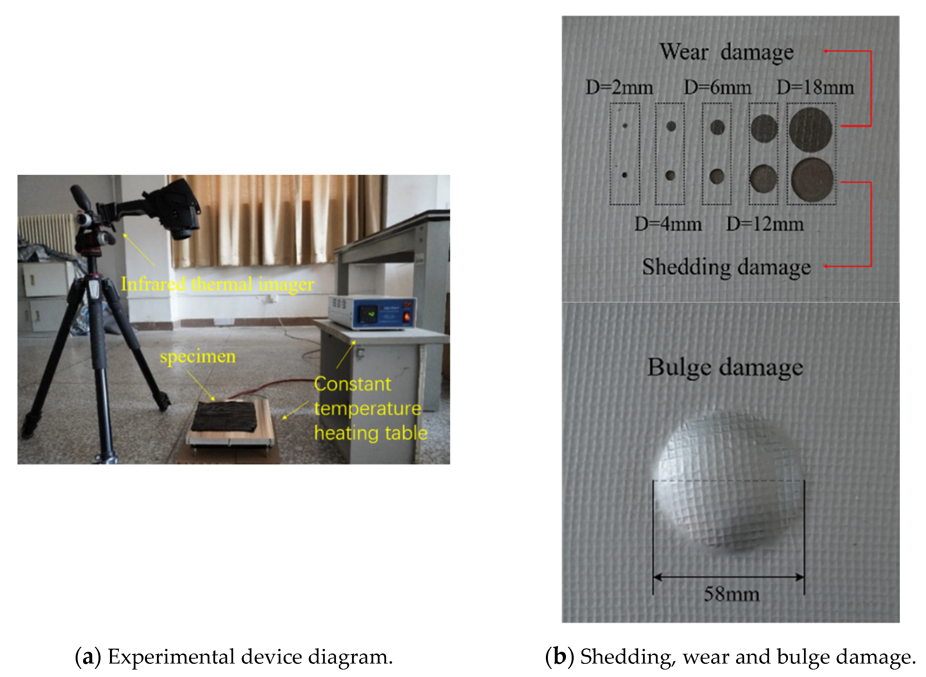
2.2. Experimental Device and Test Pieces

In this paper, portable infrared thermal imager TESTO 882 (TESTO Company, Munich, Germany) is used to measure damaged low infrared emissivity coating. The main technical parameters of the infrared thermal imager are as follows: a silicon sensor with a working band of 8–14 μm, a resolution of 320 × 240, a temperature measurement range of −20 °C–350 °C, and a temperature resolution of 0.06 °C. The experimental device diagram is shown in Figure 1.
A 180 mm × 180 mm square test piece with a low emissivity coating is shown in (b). The coating comes from Huaqin Company, Xi’an, Shanxi, China. It is a low emissivity coating with cotton thread between the coating and the base to prevent the coating from falling off easily. The coating thickness is 0.4 mm while the diameter D of the shedding damage and wear damage set by (b) are 2 mm, 4 mm, 6 mm, 12 mm, and 18 mm. A piece sets the diameter of Bulge damage to 58 mm.

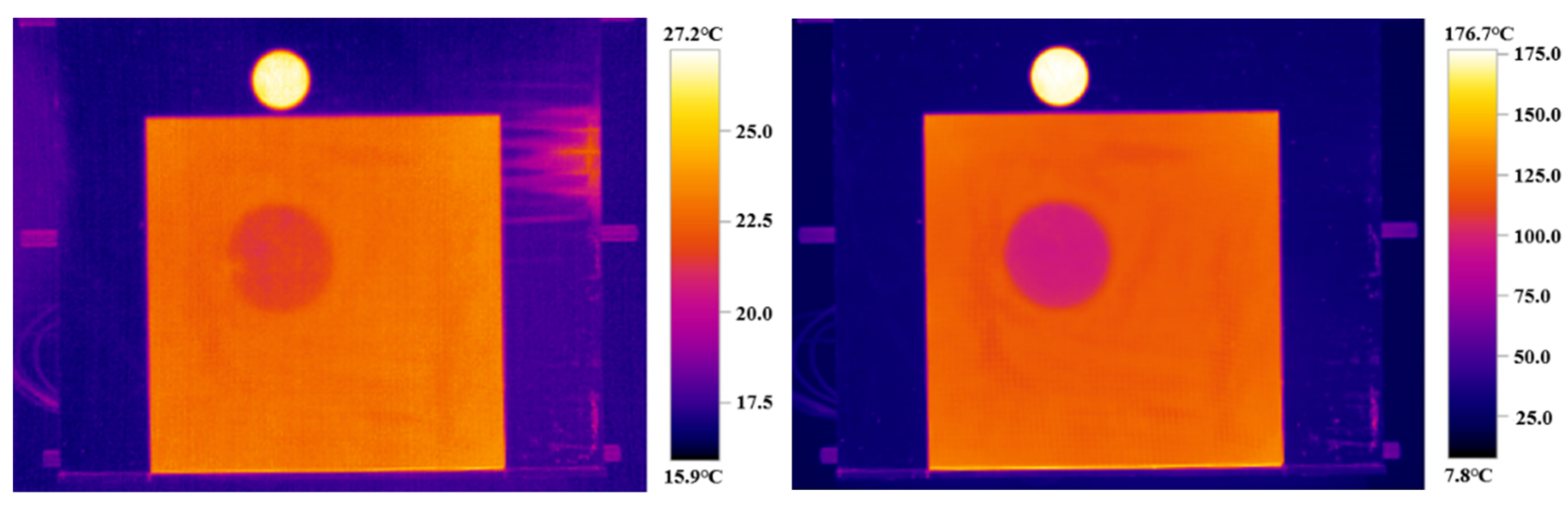
2.3. An Experiment of Measuring Emissivity by Infrared Thermal Imager

The whole specimen is heated by a STC803 constant temperature heating table produced by China Yancheng Ge Mei Electric Heating Technology Co., Ltd. The temperature range is 0 °C–400 °C. To ensure imaging stability, a tripod is used to support the portable infrared thermal imager. The test temperature range is set as 80 °C, 120 °C, 160 °C, and 200 °C. In addition, the specimens are heated by constant temperature heating table STC803. The real surface temperature T0 and ambient temperature Tu of the specimen are measured by a contact thermocouple thermometer.
Through an approximate formula, the radiation energy curves within the temperature range of (313 K, 473 K) are fitted by the Levenberg–Marquardt optimization algorithm for nonlinear curve fitting. Meanwhile, the n values under this condition are obtained, which is shown in Table 1.
The adjusted R square in the table is a parameter used to evaluate the quality of the regression equation. The closer its value is to 1, the better the curve fitting degree of the equation adopted is. The adjusted values of R square in Table 1 are all close to 1, indicating that the fitting effect of the approximate formula is relatively ideal. Figure 2 is the fitting curve in the temperature range of 313–473 K. Figure 3 is the residual between the actual value and the fitting value.
The whole specimens are heated by the STC803 thermostatic heating table. The ambient temperature Tu of the contact thermocouple thermometer is 28.4 °C. Meanwhile, the real surface temperatures of the specimen are 77.6 °C, 112.9 °C, 148.5 °C, and 181.1 °C, respectively. Figure 4 shows the infrared chart when the real temperature is 181.1 °C.
From the figure, we can find that, within the test temperature range, bulge damage is much more detached from the base metal than the debonding damage, which is blocked by the gap in the middle during heat flux conduction, resulting in lower radiation temperature than other infrared low emissivity coating parts. Shedding and wear radiation temperatures at the damaged parts are also different from the surface temperature of the coating. In addition, there is no other damage barrier when the heat is transmitted from the heating table to the damaged surface. Therefore, it can be determined that the surface emissivity changes are caused by shedding and wear, which further lead the radiation temperature to be inconsistent with the coating. Thus, shedding, wear, and debonding damage can be calculated using the direct method, while, for bulge, it needs to be recalculated using another method.

3. Result and Discussion

3.1. Processing of Emissivity Results

3.1.1. Damaged Emissivity Results Processing

As can be seen from Figure 5, the radiation temperature in shedding and wear area is different from LIREC due to the change of emissivity. The emissivity of the coating itself increases with temperature. Therefore, the real temperature can be considered as the set heating temperature. The emissivity distribution of the damaged coating at various temperatures is calculated according to Formula (6), as shown in Figure 5.
Figure 5 visually reflects the shedding and wear damage and the distribution of coating emissivity at different temperatures. When the temperature is 350.7 K, the emissivity of the intact coating is about 0.54, and the distribution is relatively uniform. The emissivity of the wear part is between 0.691 and 0.723, and the wear diameter has little influence on the emissivity of the damaged part. The emissivity is 0.726 for 2 mm diameter but between 0.433 and 0.462 for other diameters. At 385.9 K, the emissivity of the intact coating is about 0.56. The emissivity of the wear part is between 0.699 and 0.728. The emissivity was 0.729 for 2 mm diameter, but between 0.438 and 0.469 for other diameters. The emissivity of debonding area is basically the same as that of LIREC, while the emissivity of wear area is generally higher than that of coating. There is a special case for shedding damage: When the diameter of the damage area is greater than 2 mm, the emissivity of the damaged area is lower than that of the infrared emissivity coating. When the diameter of the damage area is less than 2 mm, on the contrary, its emissivity is higher than that of infrared emissivity coating. At 421.5 K, the emissivity of the intact coating is about 0.57. The emissivity of the wear part is between 0.702 and 0.733. The emissivity of a 2 mm diameter is 0.731, but the emissivity of other diameters is between 0.440 and 0.473. When the temperature is 454.1 K, the emissivity of the intact coating is about 0.61, which is higher than the emissivity of the coating at the above temperature. The emissivity of the wear part is between 0.708 and 0.739. The emissivity is 0.735 for 2 mm diameter, but between 0.444 and 0.478 for other diameters.
When the coating is applied for protection against wear, then the dark adhesive layer in the middle is exposed and the low emissivity coating is damaged, finally, causing the surface to be no longer smooth. Therefore, the emissivity of the WEAR part is higher than that of the coating. When coating shedding occurs, the base metal is exposed, resulting in very low emittance due to the high reflectivity of the unoxidized metal, which is very smooth. When the shedding area is small in diameter, the shedding area forms an approximate cavity and enhances infrared radiation so that its emittance is higher than that of the coating.
Points A, B, C, and D are selected from the intact coating, the 18 mm wear and shedding damage, and the 2 mm shedding damage, respectively, to analyze the emissivity changes.
It can be seen from Figure 6 that the emissivity of each point gradually increases with the increase of temperature. The emissivity of point B damaged by wear increases from 0.72 to about 0.74, which is much higher than that of point A intact. The emissivity of Point C of wear damage is significantly different from that of Point D. Point C is located at the site of debonding damage with A diameter of 18 mm, and its emissivity increases from 0.44 to about 0.48, which is lower than that of Point A of the intact site. Point D, at a shedding damage diameter of 2 mm, has roughly the same emissivity as point B.

3.1.2. Bulge Emissivity Results Processing of Damaged Sites

Yang introduced a variety of methods for measuring emissivity using an infrared thermal imager. In addition to the direct method, there are the double reference body method, the double temperature method, and the double background method. In the double reference method, a black body and a high diffuse reflector plate are set as the reference body, so that the black body temperature is consistent with the test piece, and the high diffuse reflector plate temperature is consistent with the background. The two-temperature rule uses a reference body with known emissivity to make it consistent with the temperature of the specimen and measures its emissivity at two different temperatures. Provide a reference body with known emissivity and keep the temperature of the reference body the same as that of the object being measured. The amount of radiation at different temperatures T 1 and T 2 is measured by thermal imager. First, a small piece of coating with known emissivity is applied to the specimen. When the temperature is T 1 , the radiation energy of the coating and the specimen are measured by a calorimeter. f R ( T 1 ) and f S ( T 1 ) are the output signals of the thermal imager, T r 1 and T s 1 are the corresponding radiation temperatures. At temperature T 2 , the thermal imager measures the radiation amount of coating and specimen, f R ( T 2 ) and f S ( T 2 ) are the output signal of the thermal imager, and T r 2 and T s 2 are the corresponding radiation temperature, where ε R is the emissivity of the reference body (coating). The double background rule is used to test specimens with known emissivity at two different background temperatures. It has been analyzed above that bulge damage is inconvenient to be measured by the direct method. Therefore, the double temperature method is adopted to measure the emissivity of bulge damage in the following text, and its emissivity calculation formula is as follows:
ε S = f S ( T 2 ) f S ( T 1 ) f R ( T 2 ) f R ( T 1 ) = ε R T s 2 n T s 1 n T r 2 n T r 1 n
Graphite with an emissivity of 0.82 is used as the reference body and placed on the heating table at constant temperature with the specimen. The temperature 30 °C, 80 °C, 120 °C, 160 °C, and 200 °C are set, and the temperature 30°C is taken as the reference temperature, the emissivity at 80 °C, 120 °C, 160 °C, and 200 °C are calculated, respectively. The infrared schemes of 30 °C and 200 °C are indicated in Figure 7.
According to the formula, the coating emissivity is calculated and shown in Figure 8. It can be seen from the figure that the emissivity calculation results of low infrared emissivity coating and its variation trend are basically consistent with that of shedding and other damaged specimens, which increases from about 0.55 to about 0.6. The emissivity of bulge damaged area is lower than that of the surrounding low infrared emissivity coating without damage, and the value of the center area is lower than that of the boundary area.

3.2. Verification of Emissivity Measurement Results

In order to verify the accuracy of emissivity measurement by an infrared thermal imager, we set the emissivity of the infrared thermal imager as the intact area, shedding, wear, debonding and bulge areas, and then measure the temperature of each region with the infrared thermal imager. If the temperature is consistent with that of the contact thermocouple, then the infrared thermal imager method is effective.
Heating temperatures of 200 °C are selected to verify the emissivity. The results are shown in Figure 9 and Figure 10 below.
Figure 9 show that the measurement of shedding and wear damage coatings by the infrared thermal imager is relatively accurate. In Figure 10, the coating emissivity calculated by the two-temperature method is also relatively accurate. For bulge damage, its temperature is lower than that of the coating. The temperature measured by the contact thermometer is 157.3 °C, which is consistent with the verification results in the thermal image.

4. Conclusions

In this study, the infrared thermal imager is used to measure the emissivity of the damaged coating, and the conclusions are as follows:
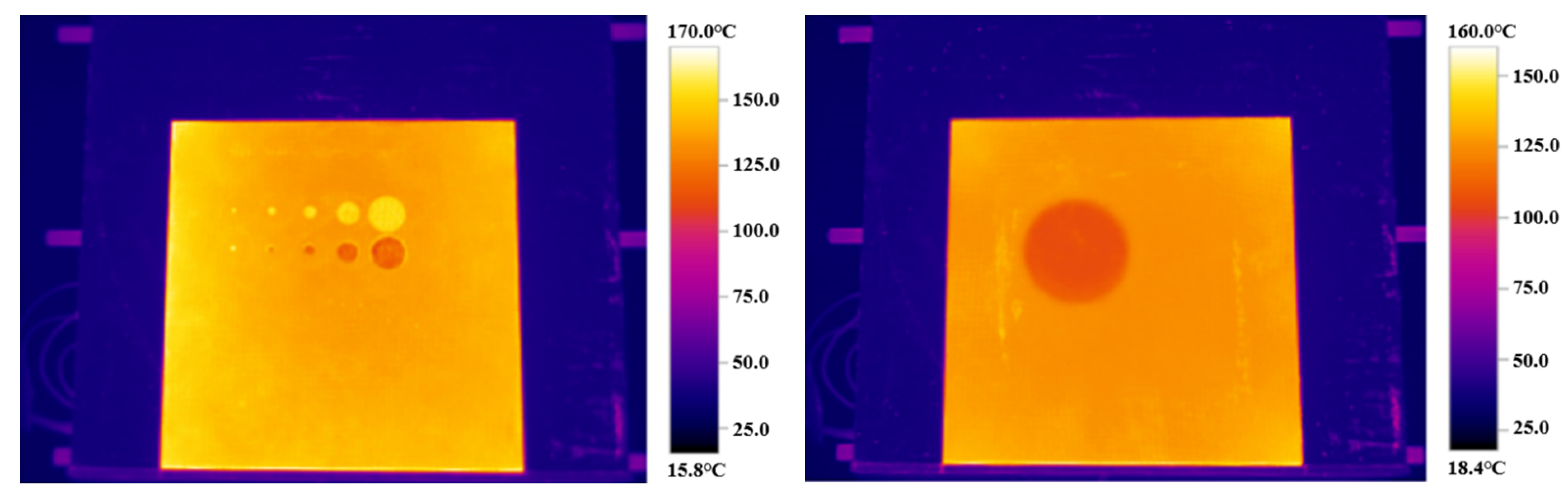
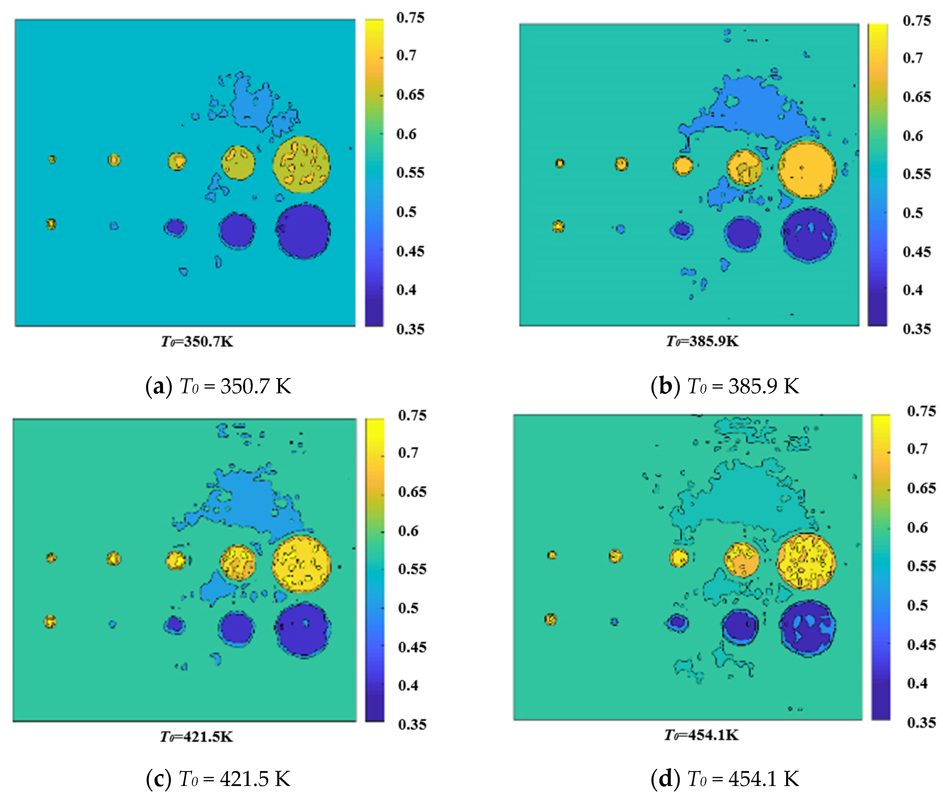
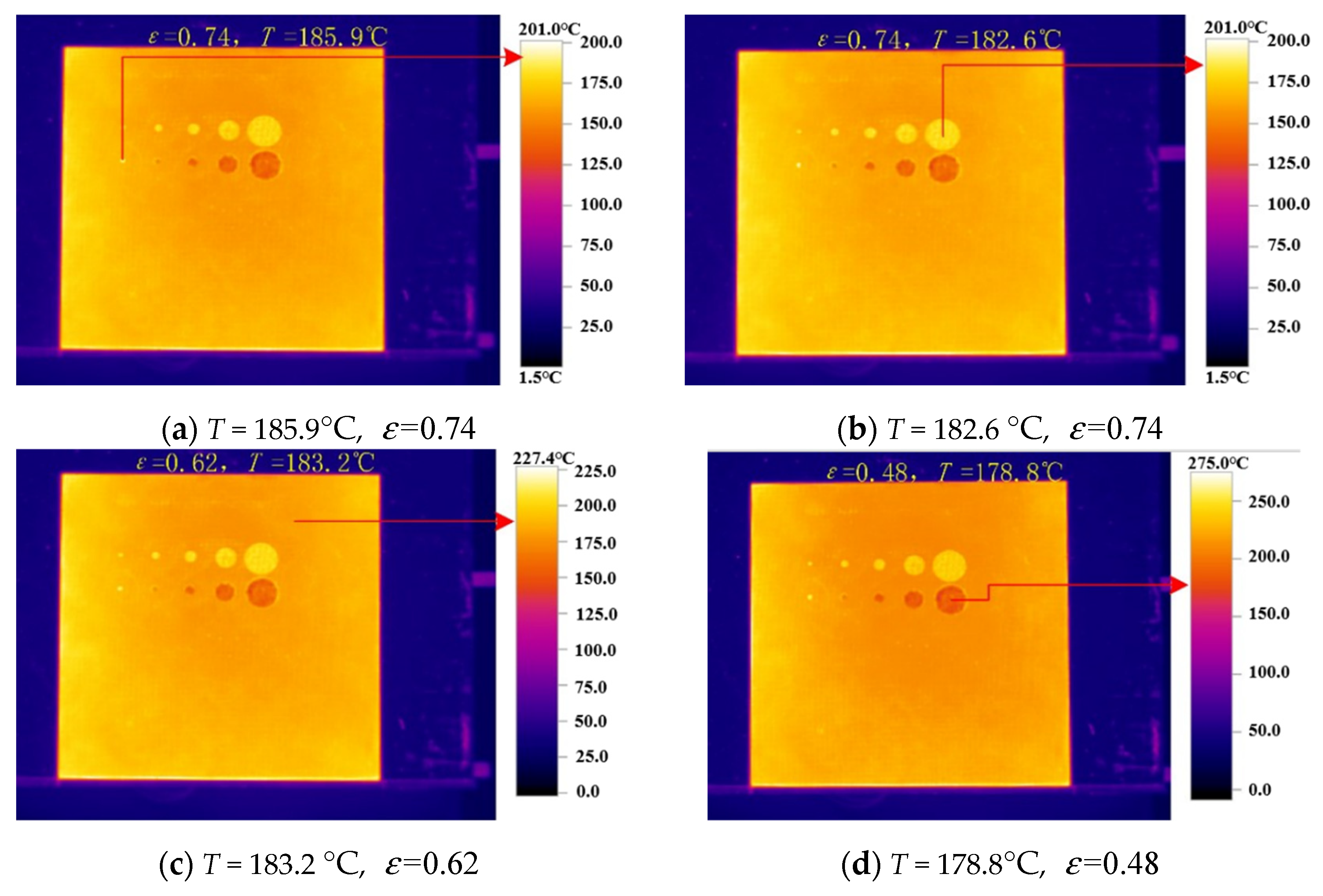
  • For shedding damage, when the damage diameter is greater than 2 mm, the emittance is mainly affected by the base metal, and the emittance value of smooth metal material is low, so the emittance value at this time is lower than that of infrared low emissivity coating. However, when the damage diameter is less than 2 mm, the emissivity increases. This is because the cavity is formed and the energy emitted is reflected several times and then absorbed by the infrared thermal imager. As a result, the calculated reflectivity becomes smaller, leading to higher emissivity.
  • Due to the exposure of the dark adhesive layer in the middle of wear damage, the low-emissivity coating is damaged and the surface is no longer smooth. Therefore, the emissivity of the wear part is higher than that of the coating, resulting in an increase in the emissivity. The impact of wear damage on the overall emissivity energy should be measured quantitatively according to the wear area in time, to evaluate whether the emission rate after wear meets the requirements.
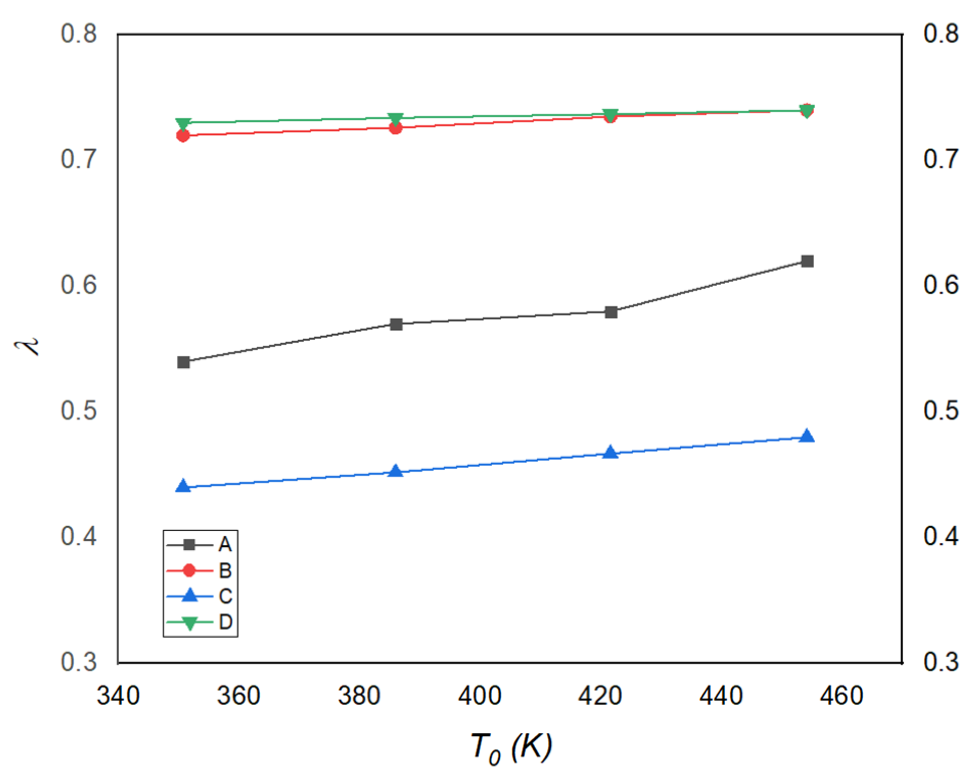
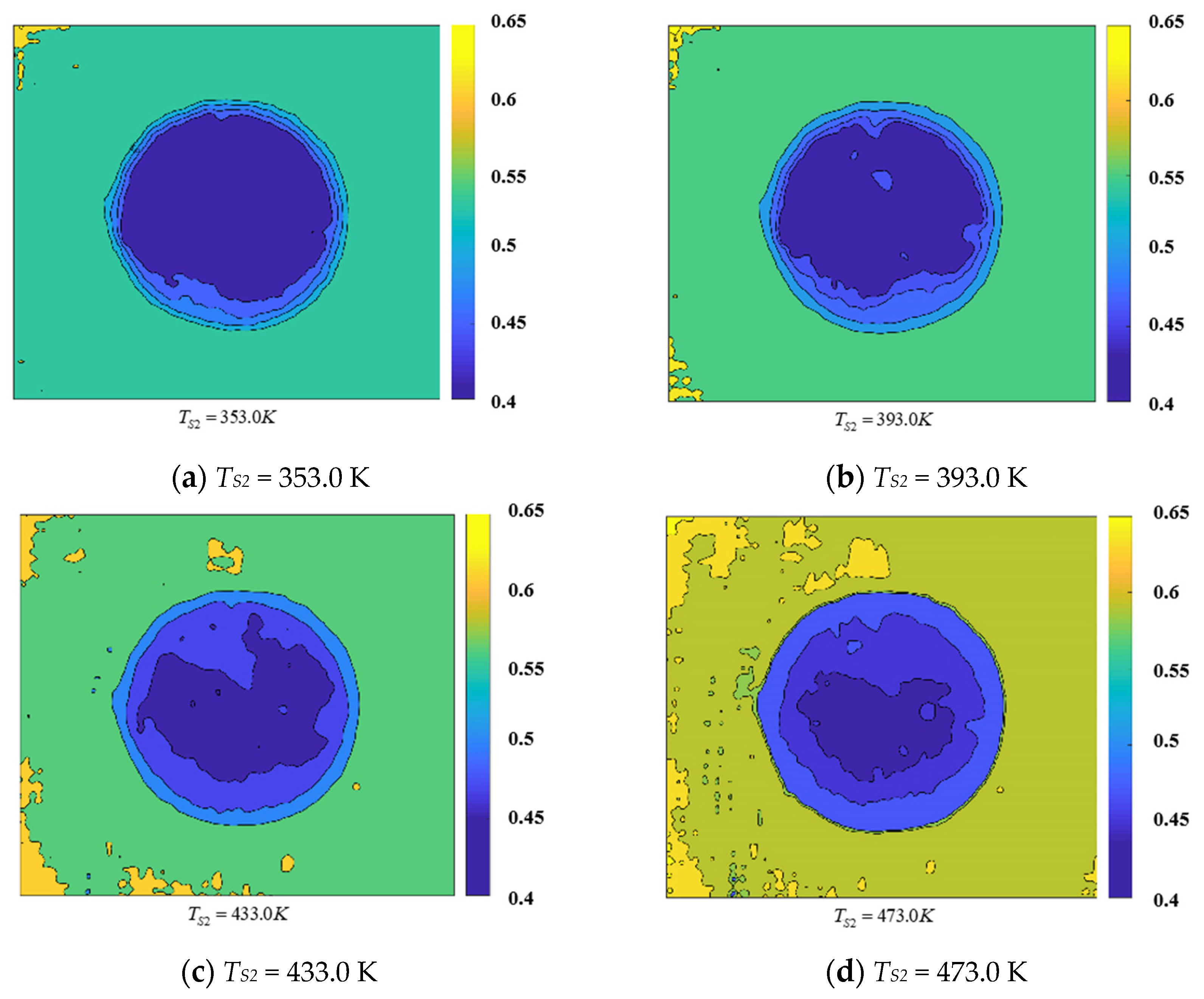
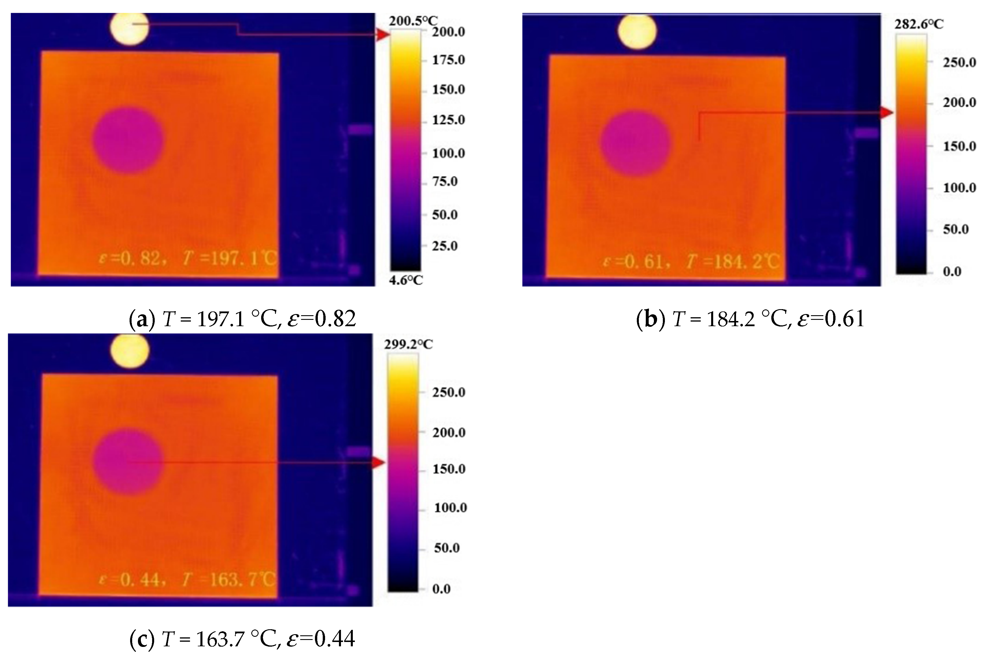
  • The emissivity of the Bulge damage site was generally higher than that of the control area and showed a gradually increasing trend with the increase of temperature, but the emissivity increased to a small extent, which was basically the same as the effect of debonding damage.
  • According to the results of this experiment, the feasibility and accuracy of the emissivity measurement method of infrared low emissivity coating defects based on a thermal imager are verified. The infrared stealth performance of the parts coated with infrared low emissivity coating can be quickly and measured on a large scale, which provides a method for comparing and measuring the stealth performance of local coating defects of equipment under certain conditions.
  • Based on the analysis of the above experimental results, it is possible to implement non-destructive testing of the damaged parts of the coating emissivity. The future research direction is how to detect the emissivity of the curved surface to adapt to the surface of objects with different shapes.

Author Contributions

Investigation, B.X.; Methodology, D.J. and Y.L.; Writing—original draft, D.J.; Writing—review and editing, W.H. and P.K. All authors have read and agreed to the published version of the manuscript.

Funding

This research received no external funding.

Institutional Review Board Statement

Not applicable.

Informed Consent Statement

Not applicable.

Data Availability Statement

The date that support the findings of this study are available from the corresponding author upon reasonable request.

Conflicts of Interest

The authors declare no conflict of interest.

References

  1. Liu, B.; Li, H.Y. Influence of surface emissivity of materials and its measurement technology progress. Ind. Metrol. 2018, 28, 90–94. [Google Scholar]
  2. Dai, J.M.; Song, Y.; Wang, Z.W. Spectral emissivity measurement technology. Infrared Laser Eng. 2009, 38, 710–715. [Google Scholar]
  3. Michael, V.; Klaus, P.M. Infrared Thermal Imaging; Verlag GmbH & Co. KGaA; Wiley: Weinheim, Germany, 2010; pp. 127–145. [Google Scholar]
  4. Monchau, J.-P.; Marchetti, M.; Ibos, L.; Dumoulin, J. Emissivity measurements of building and civil engineering materials: A new device for measuring emissivity. Int. J. Thermophys. 2014, 35, 1817–1831. [Google Scholar] [CrossRef]
  5. Li, X.M.; Li, W.J.; Gu, Z.H. Research on method of measurement of emissivity of material. J. Metrol. 2014, 35, 10–12. [Google Scholar]
  6. Tang, L.; Liu, L.; Su, J.H. Spatial resolution degradation modeling and simulation of thermal imaging system. Foreign Electron. Meas. Technol. 2014, 33, 21–27. [Google Scholar]
  7. Hou, C.G.; Zhang, G.M.; Zhao, M.T. Accurate measurement of object emissivity using infrared imaging technique. J. Infrared Millim. Waves 1997, 16, 193–198. [Google Scholar]
  8. Standard Test Methods for Measuring and Compensating for Emissivity Using Infrared Imaging Radiometers: ASTME1933-99AE; ASTM International: West Conshohocken, PA, USA, 2005.
  9. Yang, L.; Kou, W.; Liu, H.K. Surface emissivity measurement and error analysis using infrared thermography. Laser Infrared 2002, 32, 43–45. [Google Scholar]
  10. Huang, L.X.; Shen, X.H.; Song, J.T. Measure target wideband emissivity with thermal imager. Laser Infrared 2009, 39, 159–161. [Google Scholar]
  11. Xu, J.; Chen, Y.S.; Zhen, H.Y. Fabric IR emissivity as measured by IR thermal-imaging technology. Text. J. 2009, 30, 42–44. [Google Scholar]
  12. Bai, J.C.; Yu, Q.B.; Hu, X.Z. Surface emissivity measurement method based on infrared thermal imager. J. Northeast. Univ. 2013, 34, 1747–1750. [Google Scholar]
  13. Liu, H.; Ai, Q.; Xia, X.L. Measurement of infrared emissivity of surfaces with non-uniform millimeter-scale roughness. J. Eng. Thermophys. 2013, 34, 317–319. [Google Scholar]
  14. Li, Y.Y.; Qu, H.M.; Liu, W.J. Field target emissivity measurement based on the environmental radiation. Laser Infrared 2013, 43, 272–275. [Google Scholar]
  15. Liu, L.W.; Yang, M.M.; Fan, H.J. Method for surface emissivity measurement. Laser Infrared 2014, 44, 152–157. [Google Scholar]
  16. Li, Y.F.; Zhang, Z.J.; Zhao, C.Y. The infrared thermal imager is used to measure the normal emissivity of the object surface. Chin. J. Sens. Actuators 2017, 30, 1348–1351. [Google Scholar]
  17. Li, W.J.; Xu, Y.D.; Zheng, Y.J. Matching method of infrared thermal imager and surface thermocouple measurement emissivity. China Meas. Test. 2017, 43, 12–15. [Google Scholar]
  18. Alexa, P.; Solař, J.; Čmiel, F.; Valíček, P.; Kadulová, M. Infrared thermographic measurement of the surface temperature and emissivity of glossy materials. J. Build. Phys. 2018, 41, 533–546. [Google Scholar] [CrossRef]
  19. Barreira, E.; Almeida, R.M.S.F.; Simões, M.L. Emissivity of building materials for infrared measurements. Sensors 2021, 21, 1961. [Google Scholar] [CrossRef] [PubMed]
  20. Li, Y.F.; Zhang, Z.J.; Zhao, C.Y. Surface band normal emissivity measurement using infrared thermal imager. Chin. J. Sens. Actuators 2017, 30, 1348–1351. [Google Scholar]
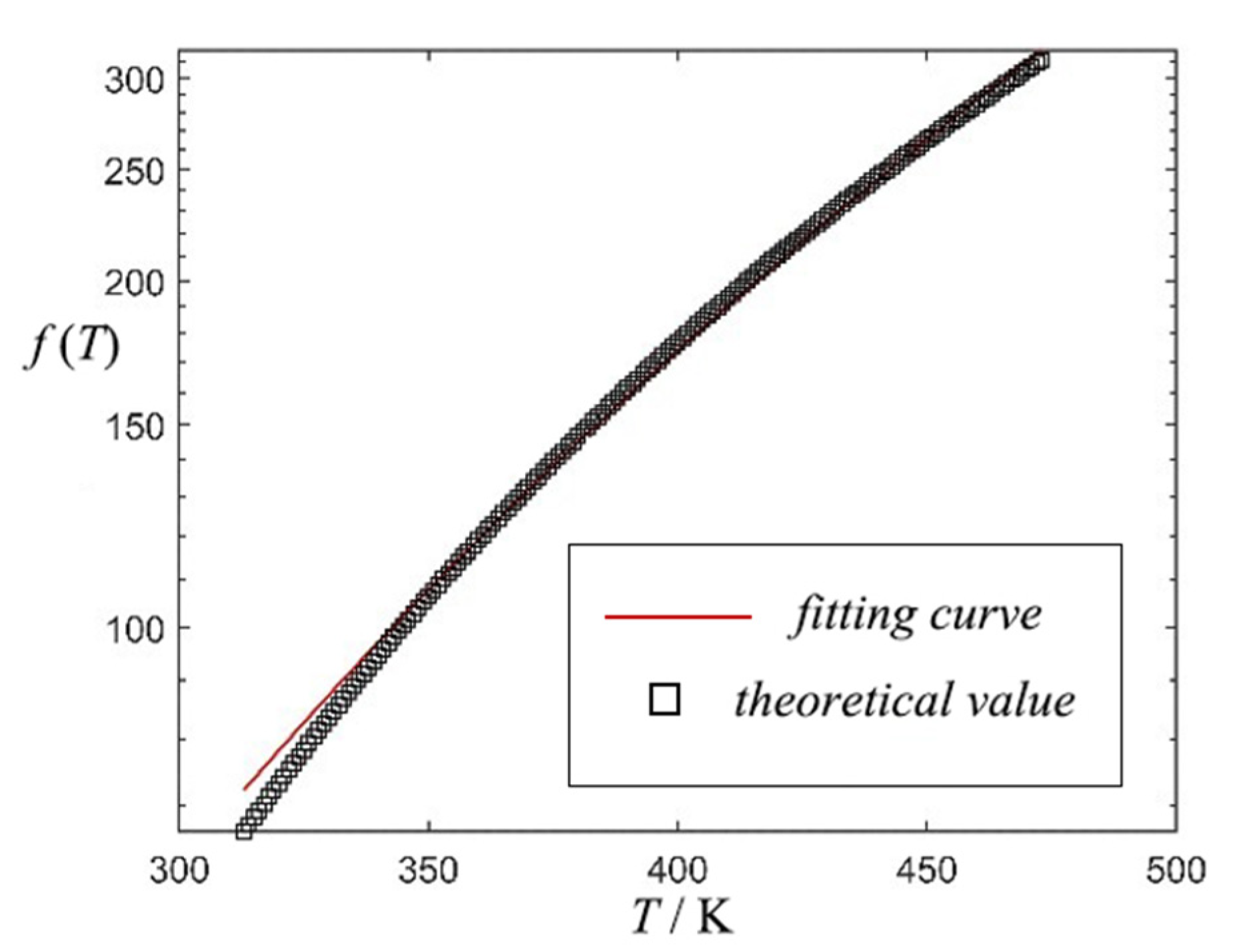
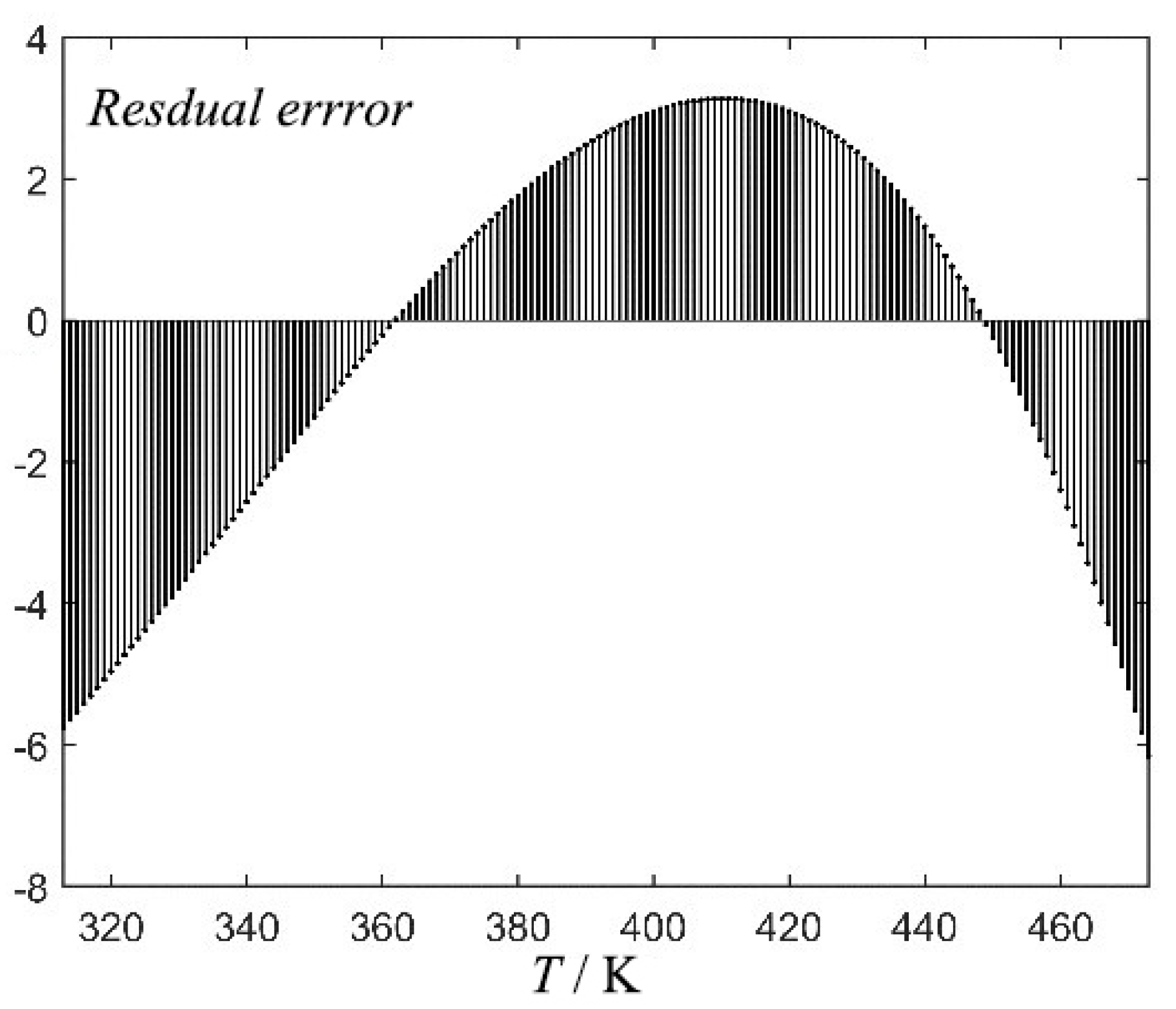
Figure 1. Experimental device and damage specimens diagram.
Surfaces 04 00021 g001
Figure 2. Fitting curve in the temperature range of 273 K–453 K.
Surfaces 04 00021 g002
Figure 3. Residuals between fitting and theoretical values.
Surfaces 04 00021 g003
Figure 4. Infrared chart at 181.1 °C, respectively.
Surfaces 04 00021 g004
Figure 5. Calculation results of damage emissivity field for shedding and wear.
Surfaces 04 00021 g005
Figure 6. Emissivity results of each analysis point.
Surfaces 04 00021 g006
Figure 7. Infrared chart at 30 °C and 200 °C.
Surfaces 04 00021 g007
Figure 8. Calculation results of the bulge damage emissivity field.
Surfaces 04 00021 g008
Figure 9. Radiation temperatures of damaged areas, shedding, and wear (181.1 °C real temperature).
Surfaces 04 00021 g009
Figure 10. Set the temperature of the constant temperature heating table to 200 °C.
Surfaces 04 00021 g010
Table 1. n values in the temperature range of testo 882 infrared thermal imager test.
Temperature Range/Kn ValueStandard ErrorAdjusted R Square
313~4733.58430.01140.9984
Publisher’s Note: MDPI stays neutral with regard to jurisdictional claims in published maps and institutional affiliations.

