Article

Low-Temperature Synthesis Strategy for MoS2 Slabs Supported on TiO2(110)

by
Mahesh K. Prabhu
and
Irene M. N. Groot
*
Gorlaeus Laboratories, Leiden Institute of Chemistry, Leiden University, Einsteinweg 55, 2333 CC Leiden, The Netherlands
*
Author to whom correspondence should be addressed.
Surfaces 2020, 3(4), 605-621; https://doi.org/10.3390/surfaces3040041
Submission received: 21 October 2020 / Revised: 3 November 2020 / Accepted: 3 November 2020 / Published: 5 November 2020

Abstract

:
MoS2 supported on oxides like TiO2 has a broad range of applications. The atomic structure of this system is therefore very useful to study. Previous research work in this area has made use of high-temperature synthesis methods, while the preparation of an MoS2/TiO2 in very important applications, such as catalysis, makes use of a low-temperature synthesis method. In this work, we investigate a low-temperature synthesis strategy for MoS2 slabs supported on rutile TiO2(110). Using scanning tunneling microscopy and X-ray photoelectron spectroscopy, we demonstrate that not only flat MoS2 slabs with irregular shapes but also MoSx stripes with a large number of coordinatively unsaturated Mo atoms are formed. In particular, it becomes evident that, for atomic structural characterization of MoS2/TiO2 and similar oxide-supported systems grown by low-temperature synthesis methods, the surface structure of the support becomes highly relevant.

1. Introduction

Nanostructured MoS2/TiO2 composites have attracted a lot of interest as a model system for applications in electronics [1,2,3], photovoltaics [4], electrocatalysis [5], and heterogeneous catalysis [6], combining a transition metal dichalcogenide (TMDC) and a wide-bandgap semiconductor. In particular, the promoted MoS2/TiO2 system is widely applied in industry, to perform hydrodesulfurization (HDS) and reduce the global SOx emissions [7,8,9]. More recently, the MoS2/TiO2 system has also found application as an efficient hydrogen evolution reaction (HER) catalyst [10].
Despite the widespread applications, many fundamental properties of the MoS2-TiO2 system, especially those relevant for catalysis, such as the atomic structure and reactivity of the edges, are disputed due to the difficulty of resolving the edge structure with sufficient contrast in conventional characterization techniques, such as electron microscopy [11,12]. Recent studies on model systems have attempted to tackle some of these challenges by using scanning tunneling microscopy (STM) and X-ray photoelectron spectroscopy (XPS). For instance, Kibsgaard et al. [6] have shown that the morphology of MoS2 slabs supported on rutile TiO2(110) depends on the atomic structure of the TiO2(110) surface and the synthesis temperature. The MoS2 slabs grown by using physical vapor deposition (PVD) at 900 K are hexagonal, while at 950 K, elongated particles are formed. Galhenage et al. [13] have investigated the effects of exposure of MoS2/TiO2(110) grown by PVD at 950 K to various gas environments, such as D2, CO, and methanol. The MoS2 slabs grown on TiO2(110) by alternative strategies, like chemical vapor deposition (CVD), have shown efficient excitonic separation between the MoS2 and TiO2 phases and, hence, better photocatalytic activity [14]. In all of these studies, MoS2 is grown at temperatures above 900 K and thermodynamically favorable pristine MoS2 slabs with well-defined edges, and the basal planes lying flat on the TiO2(110) surface are observed.
In industrially relevant systems such as a HDS catalyst, however, MoS2 is typically grown at much lower temperatures, between 573 and 673 K, using wet chemical procedures [15,16,17]. Transmission electron microscopy (TEM) studies of MoS2 grown at low temperatures on various facets of rutile and anatase TiO2 have shown the presence of “edge-on” supported MoS2 slabs [18,19]. X-ray absorption fine structure (XAFS) studies of the Mo K-edge of MoS2 slabs grown on TiO2(110) at lower temperature have indicated the presence of MoS2 clusters with Mo being in five-fold coordination or less [20,21]. Such unsaturated Mo atoms were assigned to small MoS2 clusters potentially growing as stripes on the TiO2 surface [20]. On the contrary, prior STM-based studies on MoS2/TiO2(110) fabricated by the high-temperature synthesis procedure have not observed the formation of any such structures. Given the sensitivity of the MoS2 morphology to the synthesis temperature, it is important to synthesize MoS2 on the TiO2 surface at lower temperatures, in order to gain atomic level insights, especially those relevant for industrial HDS. However, such attempts are complicated by the reactivity of the TiO2(110) substrate towards sulfur. Studies performed by other groups have shown that, depending on the temperature and the coverage, sulfur can form a plethora of structures by binding to five-fold coordinated surface Ti atoms, by replacement of the surface bridging oxygen atoms or by replacement of the near-surface in-plane oxygen atoms [22,23,24,25]. Such complications are conveniently avoided at higher temperatures, as the sulfur desorbs from the TiO2(110) surface.
In this work, we report a synthesis procedure to grow MoS2 on rutile TiO2(110) at a catalytically relevant low temperature of 650 K. We start with depositing Mo nanoparticles on a clean TiO2(110) surface. The Mo nanoparticles are thereafter sulfided by using H2S as the sulfiding agent. We make use of STM and XPS to study the morphology of MoS2. We show that our synthesis procedure yields irregular shaped MoS2 slabs with their basal planes lying flat on the substrate and “edge-on” MoSx stripes forming as elongated structures aligned along the [ 1 1 ¯ 0 ]   direction of the TiO2(110) substrate. At higher initial Mo coverage, we obtain predominantly multilayered MoS2 slabs with their basal planes lying flat on the substrate. Furthermore, we show that all of these structures adhere to a (3 × 1) lattice on the TiO2(110) surface formed by adsorption of sulfur. Additionally, we present possible atomic models supported by our experimental results to explain our findings for future theoretical work.

2. Materials and Methods

All the experiments were carried out in the ReactorSTM setup [26]. A polished rutile TiO2(110) crystal was purchased from Surface Preparation Laboratory, Zaandam, the Netherlands. The TiO2(110) crystal was cleaned by repeated cycles of sputtering and annealing. The sputtering was performed, using Ar+ with an ion energy of 1.5 keV, and annealing was performed at 873 K, for 10 min, in the presence of O2, at 2 × 10⁻⁶ mbar. Heating and cooling rates of 10 K/min were maintained to prevent cracks in the crystals due to thermal shock. The ultimate cleaning cycle involved annealing in ultra-high vacuum (UHV) at 900 K, for 10 min, to generate atomically flat TiO2(110) terraces. The cleanliness was checked with XPS and STM, until impurities were below the detection limits. The TiO2(110) crystal turned light blue after this cleaning procedure, due to the slight bulk reduction in UHV generating oxygen vacancies, which act as color centers.
Mo metal was evaporated from an Mo rod, using an Oxford EGCO4 e-beam evaporator with the TiO2 substrate held at 300 K. Coverages of Mo were checked, using XPS and samples with 0.25, 0.49, and 0.61 monolayer (ML) Mo nanoparticles were prepared as precursors for the sulfidation process. The coverage of the Mo nanoparticles was calculated from the XPS spectra by comparing the peak areas of Mo 3d and Ti 2p signals after correcting for the relative sensitivity factors [27]. The sulfidation was carried out by heating the samples to 650 K for 45 min in an H2S atmosphere of 1 × 10⁻³ mbar. Thereafter, the samples were cooled to room temperature in UHV.
Scanning tunneling microscopy was performed at room temperature, using the UHV mode of the ReactorSTM. Polycrystalline Pt-Ir 90-10 wires purchased from Goodfellow were cut and used as STM tips without further processing. Constant-current scans were performed, using LPM video-rate scanning electronics, described in detail elsewhere [28,29]. Home-developed Camera software and WSxM were used for STM image processing [30]. Most-common normal filtering was used to obtain a correctly connected surface in order to calculate the height profiles. Line-by-line background subtraction was used, otherwise, for the ease of viewing. No other processing was performed on the STM images reported in this paper.
The XPS measurements were performed in a SPECS Phoibos system equipped with an XRM50 X-ray source set to the Al K-alpha line, used along with a monochromator, to excite the sample with a beam spot of 0.4 mm diameter, at 55° incidence. The acceleration voltage was set to 10 kV, and a power of 250 W was used for all the measurements. The HSA3500 hemispherical analyzer with a pass energy of 30 eV was employed to analyze the photoemission. The bulk Ti2p peak set to 458.5 eV was used to calibrate the XPS spectra obtained [31]. The calibration was further checked by using a separate clean Au(111) crystal by confirming the peak position of Au4f at 84 eV. The number of integrations was set to 20. The data thus obtained were characterized and quantified, using CASA-XPS and with relative sensitivity factors reported in the literature [27]. The XPSPEAK41 software was used for peak fitting the Mo 3d and S 2p spectra. The Mo 3d and S 2p peaks were fit, using mixed Gaussian–Lorentzian (65–35) curves. Shirley background subtraction was applied and a non-linear least squares method was used for peak fitting. The Mo 3d spectrum was fit with components for Mo (228.0 eV), MoOx (228.7 eV), and MoO2 (229.8 eV) for the Mo nanoparticles and MoS2 (229.2 eV), MoSx (228.8 eV, 228.3 eV), and the S 2s (226.2 eV) component for the Mo sulfide samples. The MoSx has two components arising from 5-fold and 4-fold coordinated Mo atoms. The S 2p spectra were fit with components for S2−(161.8 eV) and bridging S22− (163.1 eV) doublets separated by 3.15 and 1.16 eV, respectively. These binding energies are tabulated in Table 1, and they are based on previous experiments reported in the literature [32,33,34,35,36,37,38,39].

3. Results and Discussion

A clean TiO2(110) surface with atomic steps produced by our cleaning procedure is shown in Figure 1a. The height of steps (Figure 1b) is measured to be 3.19 Å and is very close to the monoatomic step height 3.24 Å of TiO2(110) [40]. The terraces show bright and dark rows along the [001] direction (Figure 1c,d) characteristic of a slightly reduced UHV-annealed TiO2(110) surface [22,40,41,42]. The bright rows in Figure 1c are attributed to the Ti4+ atoms with five-fold coordination, and the dark rows are attributed to the bridging oxygen atoms of the rutile TiO2(110) atomic structure [43]. Figure 1d shows the presence of dark spots on the bright rows of the (1 × 1) structure. These features have been interpreted as sub-surface oxygen vacancy sites in a previous study [42]. The bright features on the dark rows which are expected for surface oxygen defects are not imaged here [42,43,44]. Pt-Ir tips are known to be prone to a tip state where these features are not imaged and the appearance of the dark features are enhanced [42]. The bright features observed in Figure 1d are likely due to residual –OH groups on the surface [44].
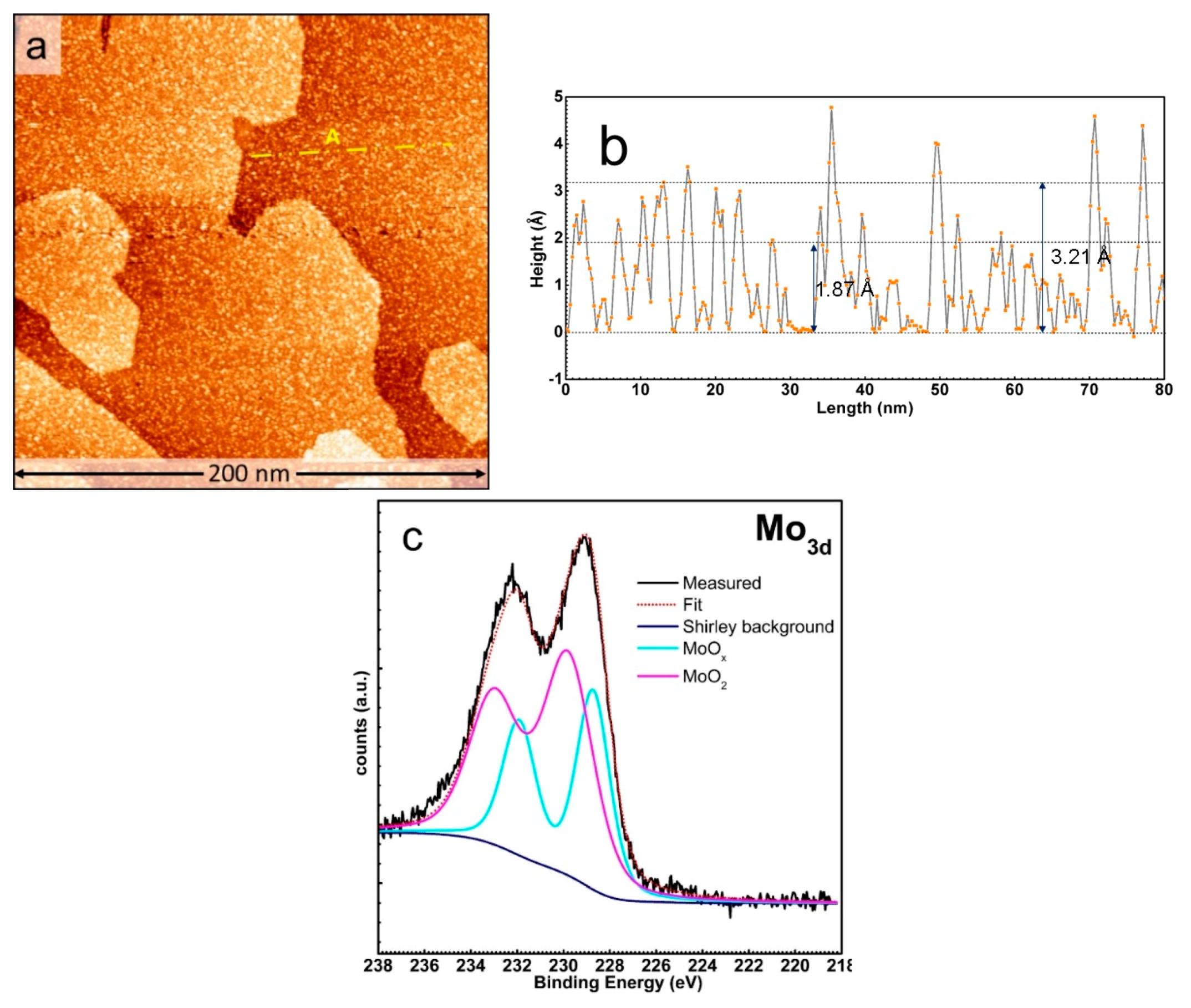
Mo metal was evaporated onto the clean TiO2(110) surface by physical vapor deposition from an Mo, rod as detailed in the experimental methods. Figure 2a shows the large-scale STM image of the Mo nanoparticles supported on the TiO2(110) surface grown to a coverage of 0.25 ML of Mo. The Mo nanoparticles are observed to nucleate randomly on the TiO2(110) terraces and are 1.8–3.2 Å high (Figure 2b). Some nanoparticles of 4–5 Å height are also observed. The Mo nanoparticles uniformly cover the TiO2(110) surface and preference for any nucleation site was not observed. Furthermore, the Mo 3d XPS spectrum (Figure 2c) shows a peak at 228.8 eV, which is less than the expected 229.2 eV for Mo4+, suggesting that the particles have an overall oxidation state of less than 4. Peak fitting shows the presence of Mo4+, as well as a sub-stoichiometric Mo oxide component, suggesting that the particles are of the form MoO2−x. The lack of a preferred nucleation site and the oxidation of Mo nanoparticles on the TiO2(110) surface suggest a very strong substrate–overlayer interaction. Such a strong Mo-TiO2(110) interaction has been observed in the previous studies on this system [32,33,34,35,45,46]. The nature of interaction between metal nanoparticles and the TiO2 surface depends on the initial heat of adsorption of oxygen on the respective metal nanoparticle, in comparison to the initial heat of reduction of TiO2. In the case of Mo, the heat of absorption of oxygen is greater than the heat of reduction of TiO2. Therefore, the transfer of oxygen from the surface to the Mo nanoparticles leading to their partial oxidation is thermodynamically favorable [46]. The Mo nanoparticles thus formed are known to have an oxidation state of less than 4, as observed in our experiment. Similar behavior is also observed for reactive metals with high heat of oxygen adsorption, such as Re, Al, Hf, Cr, and Mn supported on TiO2 [47,48,49]. Growing Mo nanoparticles to higher coverages, for instance, to 0.49 ML, leads to an increase in their metallicity, as is evident from the overall 0.4 eV shift of the Mo 3d spectrum to lower binding energy (see Supplementary Materials Figure S1). The peak fits also show a non-zero contribution from the metallic Mo signature at 228.0 eV. This increase in the metallicity of Mo is attributed to the kinetic limitations of oxygen diffusion from the bulk TiO2 to Mo nanoparticles and was observed in previous studies, as well [32].
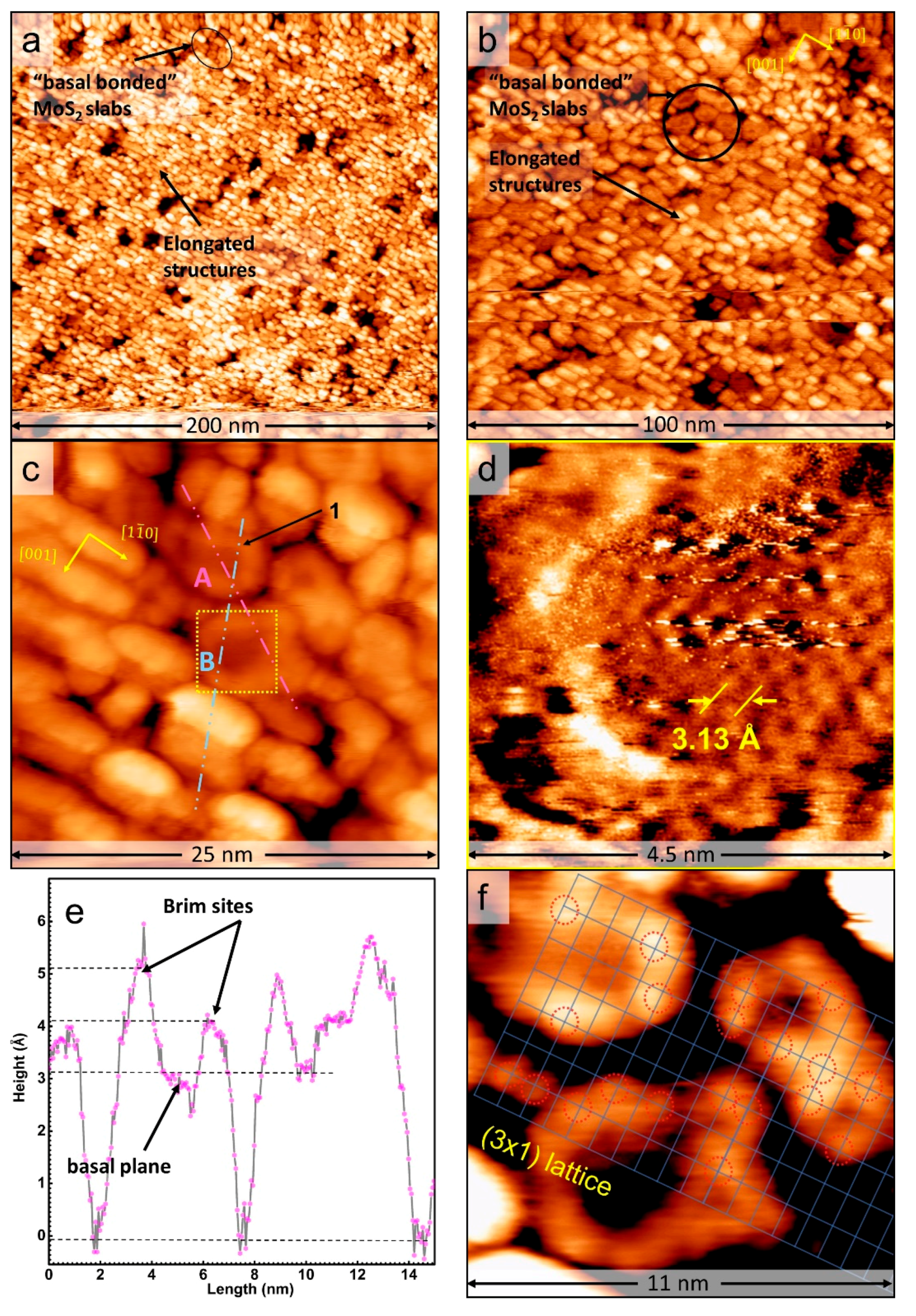
The Mo nanoparticles thus prepared were sulfided at 650 K in a H2S atmosphere of 1 × 10⁻³ mbar, as detailed in the experimental methods. Figure 3a,b shows large-scale STM images of MoS2 slabs on TiO2(110) formed after the sulfidation process. Upon sulfidation, the atomically flat structures with a dark relative contrast and a bright rim along their perimeter are formed. We identify these structures as MoS2 slabs with their basal planes lying flat on the TiO2 (110) support and refer to them as “basal-bonded” MoS2 slabs in the rest of this article. These MoS2 slabs are of 3–5 nm size and predominantly have an irregular shape (Figure 3b,c). The “basal-bonded” MoS2 slabs, despite their irregular shape, appear to be slightly elongated along the [ 1 1 ¯ 0 ] direction. This is in contrast to the MoS2 slabs grown by the high-temperature synthesis methods used in prior studies where highly elongated particles with well-defined edges aligned along both the [001] and [ 1 1 ¯ 0 ] directions were observed [6,13]. Kibsgaard et al. [6], in particular, observed a strong dependence of the shape of the MoS2 slabs on the synthesis temperature. The irregular edge shapes of the “basal-bonded” MoS2 in our experiments are likely driven by the strong interaction of Mo nanoparticles with the TiO2(110) substrate, as well as the adsorption of S on TiO2(110), which, in turn, strongly depends on the temperature [22,23,24,25,50]. The atomic resolution of the basal planes of the “basal-bonded” MoS2 slabs shows an interatomic distance of 3.13 Å (see Figure 3d), which matches well with the reported S-Mo-S distance of 3.15 Å of the (0001) basal plane of single-layer MoS2 slabs [51]. This further shows that the “basal-bonded” MoS2 slabs grown in this experiment are crystalline in nature. Atomic resolution along the edges was, however, difficult to obtain due to the low conductivity of the titania substrate. Furthermore, the tendency for rapid tip changes due to the mobile sulfur species present on the sample made it difficult to maintain the tip state required for the atomic resolution of the MoS2 basal planes.
The observed bright rim along the periphery of the MoS2 slabs was attributed to the electronic effects of one-dimensional metallic states on the edges of the MoS2 slabs called Brim sites [52]. The bright rim of “basal-bonded” MoS2 slabs supported on TiO2(110) is, however, more diffuse as compared to MoS2 on metallic supports like Au(111). These Brim sites were also observed on MoS2 slabs grown on TiO2 at 900 K [6]. The measured height along the line marked A in Figure 3c (shown in Figure 3e) shows that the “basal-bonded” MoS2 slabs have the edge protrusions measured up to 5.1 ± 0.1 Å high, while the basal planes are measured to be 3.3 ± 0.2 Å high, which is close to the theoretical S-Mo-S distance of 3.15 Å. However, the single-layer MoS2 slabs with measured height of up to 4.7 Å were reported in previous studies [6,13]. The measured height of MoS2 is strongly influenced by electronic effects due to the chemical state of the tip, applied sample voltage, and MoS2-TiO2 interactions, as well as the conductivity of the substrate, which, in turn, is influenced by the cleaning procedure and fate of the substrate due to the inevitable sulfur-TiO2 chemical reactions at the lower synthesis temperature used in our experiment. Therefore, the comparison of our measured heights with the previous literature reports becomes difficult. Since nearly all of the “basal-bonded” MoS2 slabs have the same relative contrast with respect to the TiO2(110) steps, we conclude that the synthesis procedure yields predominantly single-layer “basal-bonded” MoS2 slabs. Furthermore, we observe that there are two types of Brim sites with a measured height difference of ~1 Å. This is attributed to the Mo- and S- terminated edges of the MoS2 slabs having slightly different electron densities at the respective Brim sites. Furthermore, the electron density at these Brim sites was found to have maxima (bright spots) at the corner sites of the irregular “basal-bonded” MoS2 slabs. Analysis of the locations of these corner sites of nearby “basal-bonded” MoS2 slabs showed that the bright spots were located at positions which were integral multiples of ~6.2 Å along the [ 1 1 ¯ 0 ] direction and ~8.9 Å along the [001] direction, thus fitting a (3 × 1) TiO2(110) lattice (see Figure 3f) strongly suggesting that these bright spots are related to bonding of the MoS2 slabs with the substrate, likely through an edge sulfur atom. Theoretical calculations, using density functional theory (DFT) on the influence of the substrate interactions, are necessary to correctly assign the edge terminations.
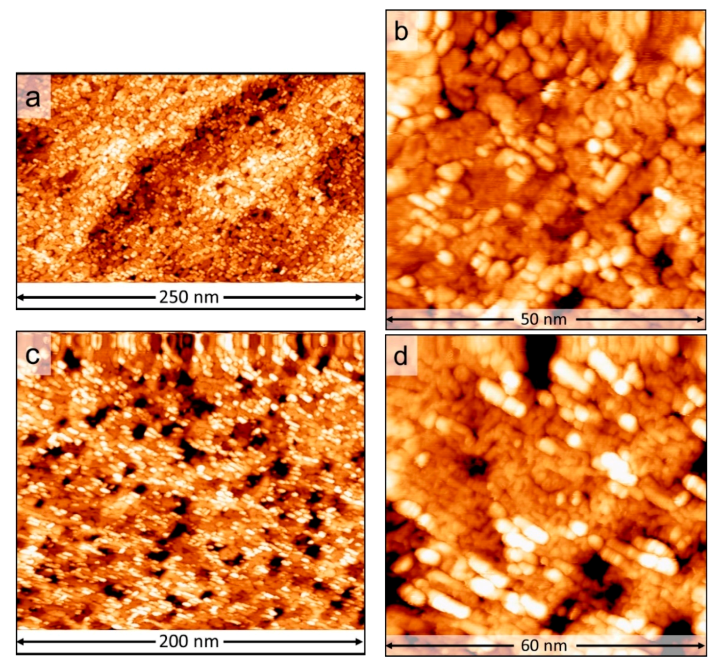
Increasing the initial coverage of Mo nanoparticles to 0.49 ML followed by sulfidation also formed “basal-bonded” MoS2 slabs. However, the slabs were observed to merge along at least one of their edges, thus forming effectively larger-size MoS2 slabs. This effect can be seen in Figure 4a and is better resolved in Figure 4b. The “basal-bonded” MoS2 slabs thus formed retain their irregular shape and also have an atomically flat basal plane with a dark relative contrast. However, we also observed the formation of a significant number of slabs with a brighter contrast. Height lines along the basal planes of these slabs show a measured height of ~5.8 Å, suggesting the formation of a second layer (see Supplementary Materials Figure S2). Upon further increasing the coverage of Mo nanoparticles to 0.61 ML, followed by sulfidation, the MoS2 slabs are predominantly “basal-bonded” and are multilayered, as is evident from their STM contrasts (see Figure 4c). As the substrate is already completely covered at this Mo coverage, determining the number layers of “basal-bonded” MoS2 slabs from the STM images becomes difficult. However, a layer-by-layer growth of the MoS2 slabs is evident from our experiments up to a coverage of 0.61 ML Mo.
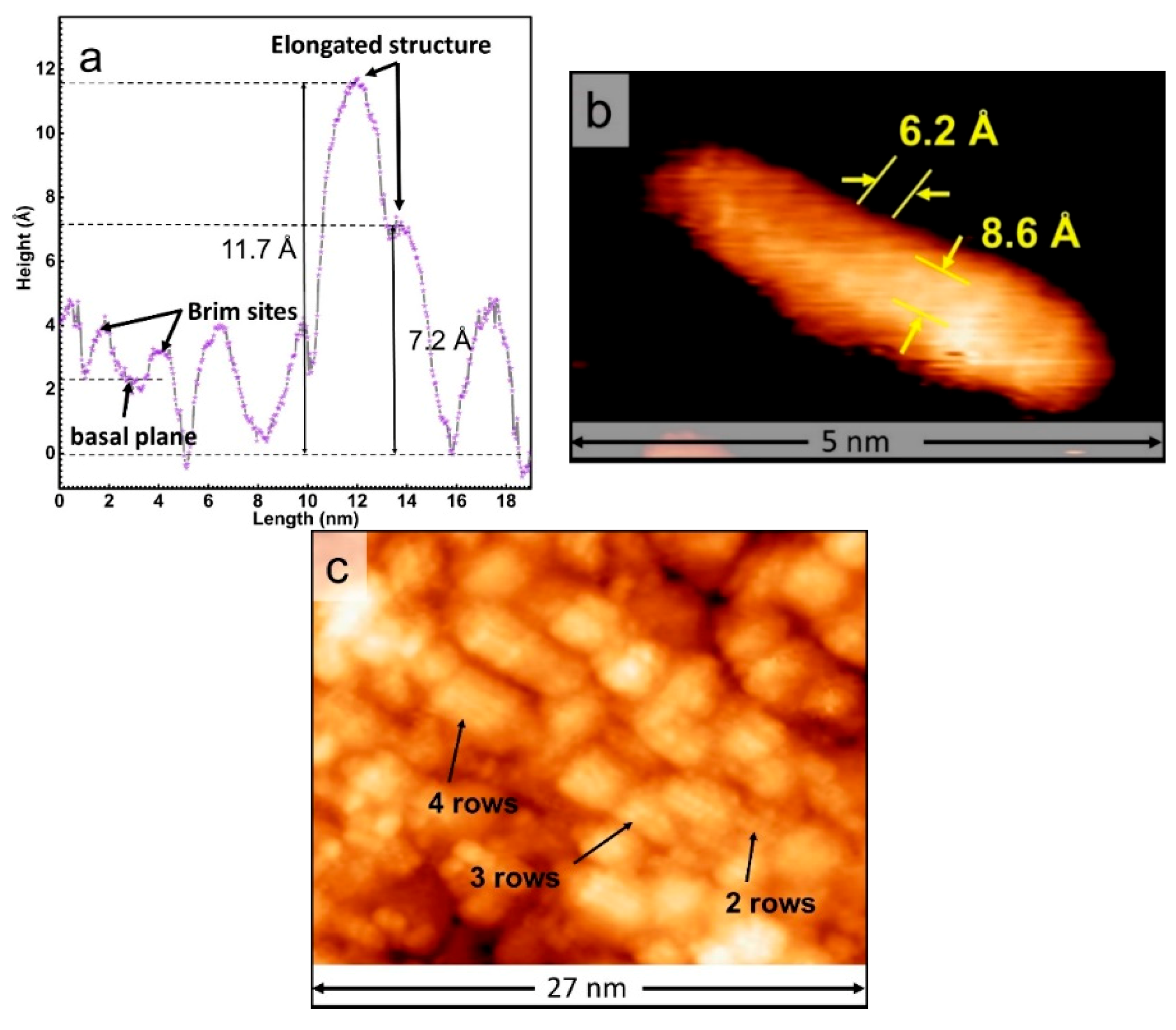
In addition to the “basal-bonded” MoS2 slabs, we also observe the formation of several elongated structures aligned along the [ 1 1 ¯ 0 ]   direction for all the coverages of Mo nanoparticles presented in this work. These elongated structures have both intermediate and bright relative contrasts with respect to the “basal-bonded” MoS2 slabs, as seen in the large-scale STM images in Figure 3a and Figure 4a,c. These structures have not been observed to form in the previous studies involving the high-temperature synthesis of MoS2 on TiO2 at 900 and 950 K. The measured height along the line marked B in Figure 3c over one such elongated structure is shown in Figure 5a. The elongated structures were measured to have a height of 7.2 ± 0.2 Å for the intermediate contrast ones and 11.7 ± 0.4 Å for the bright contrast ones. Additionally, the elongated structures are 3–5 nm in length and are formed without a preferred location as is seen from their uniform distribution on the TiO2(110) steps in Figure 4a. Furthermore, these elongated structures are resolved into a row of bright spots separated by 6.2 ± 0.1 Å (see Figure 5b). The elongated structures typically consist of two to four of these rows, separated by 8.6 ± 0.2 Å (see Figure 5b,c). These distances fit well with a (3 × 1) TiO2(110) lattice, suggesting that strong substrate interactions are present and likely play a key role in the formation of these structures. We also observed that the number density of the elongated structures decreases sharply with increasing the Mo coverage from 0.25 to 0.49 ML but only decreases slightly with further increasing the Mo coverage to 0.61 ML (see Supplementary Materials Table S1). However, we also observe that the elongated structures always have a higher STM contrast than that of the “basal-bonded” MoS2 slabs irrespective of the number of layers of MoS2 grown, suggesting a more metallic nature of the elongated structures. For example, in the case of Mo coverage of 0.25 ML, a relative height difference of up to 8.3 ± 0.4 Å (see Figure 5a) is measured between the elongated structures and the basal planes of nearby “basal-bonded” MoS2 slabs, while in the case of Mo coverage of 0.61 ML, a height difference of 7.4 ± 0.2 Å (see Supplementary Materials Figure S2) is measured. However, one may expect that the geometric effect growing multiple layers of “basal-bonded” MoS2 slabs eventually offsets the electronic effects of an adjacent, more metallic elongated structure, and, therefore, the contrast difference between the MoS2 phase and the elongated structures should decrease with increasing coverage of Mo. The measured height difference clearly contradicts this expectation. This observation may, however, be explained by the vertical growth of the elongated structures with respect to the TiO2 substrate.
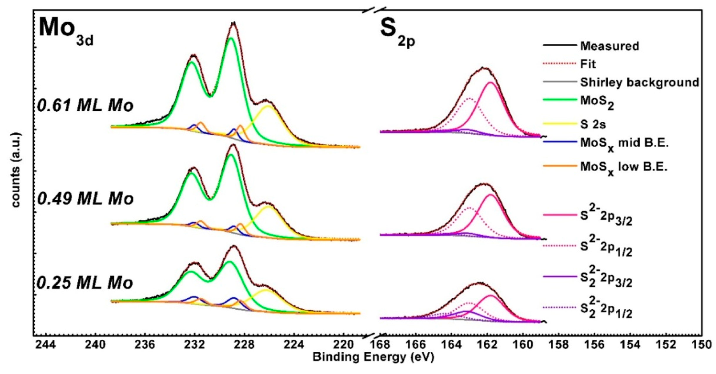
The Mo 3d and S 2p spectra of all sulfided samples are shown in Figure 6. After sulfidation, irrespective of the coverage, all the Mo 3d spectra show a doublet with peaks at 229.2 and 232.3 eV which are identified as those of MoS2 and a shoulder at 226.1 eV, which is identified as an S 2s feature. The Mo 3d doublets were fit based on the interpretations by Bruix et al. [36]. The observed Mo 3d signal has no components of Mo5+ and Mo6+ states, suggesting complete conversion to MoS2 and no residual Mo oxysulfides within the detection limits of the XPS measurements. This matches very well with our STM observations. Furthermore, the data also suggest the presence of sub-stoichiometric MoSx due to non-zero components at 228.7 and 228.3 eV. These two components have been assigned by Bruix et al. to coordinatively unsaturated Mo atoms bound to sulfur, such as the edge Mo atoms of an MoS2 slab. Such coordinatively unsaturated Mo atoms have a lower oxidation state than that of the Mo atoms in the basal plane of an MoS2 slab and, hence, a lower binding energy signal in XPS. Upon increasing the coverage of Mo from 0.25 to 0.49 ML, it is observed that the MoS2:MoSx ratio increases. However, a further increase of Mo coverage to 0.61 ML does not change this relative ratio significantly, as it is seen in Table 2. The S 2p peak shows a slight red-shift from 162.2 to 162 eV upon increasing the coverage of Mo. The corresponding S 2s spectra also show this behavior. Furthermore, the S 2p peak for low-coverage MoS2 shows an asymmetry on the higher binding energy side of the peak. Fitting is performed with components for S2− and S22− [37,38,39,53]. The S22− states are attributed to the presence of double S atoms on the edges of the MoS2 slabs [38,39]. Our fits indicate an increase in the S2−:S22− ratio (see Table 2) upon increasing the Mo coverage to 0.49 ML, but the ratio remains the same within experimental errors upon further increase of the amount of Mo. This observation corresponds to the changes in the MoS2:MoSx ratio noted from the Mo 3d spectra. Furthermore, the Mo:S ratio remains fairly constant at ~1:2.2 upon increasing the coverage of Mo. The ratio of 1:2.2 is very close to the expected value of 1:2 for MoS2. The extra sulfur could be attributed to the adsorption of S on TiO2. The component for these sulfur atoms could not be satisfactorily resolved in the peak fits for S 2p, due to overlap with the S22− component [24].
In order to gain insights into the fate of the TiO2(110) support after the sulfidation of the Mo nanoparticles, the STM images of the sample obtained after sulfiding 0.25 ML Mo nanoparticles were analyzed at high contrast to highlight the substrate (see Supplementary Materials Figure S3). A characteristic (3 × 1) structure on the substrate that is identical to the well-known (3 × 1) sulfur adsorption structure of TiO2(110) was observed to form on the exposed areas of the TiO2 support [22,24]. It is expected that the exposure to H2S at elevated temperatures drastically changes the surface structure of the TiO2(110) surface. The extensive studies on S-TiO2 interactions in the past [22,23,24,25,50,54,55] have shown that the interaction is very complex and can result in a wide variety of structures depending on the S coverage and temperature of adsorption. For instance, at room temperature, sulfur adsorbs on the exposed titanium atoms (five-fold coordinated) of TiO2(110) but does not form ordered structures. When the temperature is increased to 573 K, the bridging oxygen atoms are systematically replaced by sulfur which eventually forms a (3 × 1) ordered structure. At 673 K, the in-plane oxygen atoms are replaced by the sulfur atom pairs, forming an ordered (3 × 3) and ultimately a (4 × 1) structure [23,24]. Typically, the TiO2(110) surface has multiple structures co-existing depending on the sulfur coverage at that given temperature as has been demonstrated by STM and low-energy electron diffraction (LEED) experiments [24]. Based on these studies, at 650 K, the temperature used for MoS2 synthesis in our experiments, the formation of (3 × 3) and (4 × 1) domains is expected on TiO2(110). We did not observe such structures in any of the STM images where the substrate is exposed. Instead, only a (3 × 1) structure associated with a slightly lower coverage of sulfur was observed to form on the exposed areas of the substrate. This can be explained by considering the presence of the overlayer of partially oxidized Mo nanoparticles, which can act as a sulfur sink and compete with TiO2 for the sulfur atoms, thereby resulting in an effectively lower sulfur coverage on the TiO2 substrate, since Mo nanoparticles have a higher affinity for sulfur. Therefore, a (3 × 1) structure, corresponding to a lower sulfur coverage, is likely to form. We also point out that (3 × 1) domains are also formed at elevated temperatures, as have been observed in previous experiments [24].
Given our observation that the bright spots on the “basal-bonded” MoS2 slabs conform to a (3 × 1) lattice, we propose that the overall rounded structure of the MoS2 slabs is due to interactions of the edges with the (3 × 1) S adsorption structure on TiO2(110). This is not surprising, as prior studies have shown that the morphology and stoichiometry of Mo sulfides strongly depend on the interactions with the support [56,57,58,59,60]. Taking into account the observation that the “basal-bonded” MoS2 slabs are oriented along the [ 1 1 ¯ 0 ]   direction, we present a possible atomic model to account for our experimental findings. We take the case of the “basal-bonded” MoS2 slab marked 1 in Figure 3c. The proposed atomic model for this MoS2 slab is shown in Figure 7a. In our model, a pair of opposite edges of the MoS2 slab with S- and Mo-terminations are oriented along the [ 1 1 ¯ 0 ]   direction of the TiO2(110) surface with the (3 × 1) sulfur structure. The terminating S atoms along these edges interact with both the five-fold and four-fold coordinated Ti atoms of the (3 × 1) structure. The S-S distance in the basal plane of MoS2 is 3.15 Å, which matches well with the distance of 6.2 Å of the alternate Ti rows in the (3 × 1) structure of TiO2(110) facilitating an MoS2 edge—substrate Ti interaction for every alternating S atom of the MoS2 edges. This may also be visualized by considering alternating lower edge S atoms lying close to the TiO2(110) surface as belonging to the (3 × 1) TiO2(110) structure. Furthermore, the STM images of all the “basal-bonded” MoS2 slabs show that the corner sites of the slabs appear very bright, suggesting a high metallicity of these sites. Similar bright corner sites have been observed in Ni-promoted MoS2 slabs supported on gold, where some slabs adopt a more rounded shape, with corner sites having coordinatively unsaturated Ni and Mo atoms [52]. The edge sites in these experiments have coordination numbers less than 5. Furthermore, the XAFS studies of promoted and unpromoted MoS2 catalysts supported on TiO2 showed that, for small MoS2 slabs, Mo atoms tend to have coordination numbers between 4 and 5.5, resulting in sulfur-deficient edge terminations which are stabilized by bonding to the TiO2 substrate [20,21]. We propose that the terminating corner sites in the “basal-bonded” MoS2 slabs in our experiments are formed due to an unsaturated Mo atom of less than 6 coordination number. The conformation of the MoS2 slab to the (3 × 1) sulfur structure likely stabilizes these coordinatively unsaturated Mo sites. As a comparison, we overlay the particle marked 1 in Figure 3c over our atomic model (see Supplementary Materials Figure S4). A visual comparison clearly shows a close match between the locations of the bright spots in the STM image and locations of coordinatively unsaturated Mo corner sites in our atomic model.
In addition to the “basal-bonded” MoS2 slabs, the elongated structures are also oriented along the [ 1 1 ¯ 0 ] direction of the TiO2 substrate. Furthermore, these structures have rows of bright spots that also closely fit a (3 × 1) lattice, suggesting strong substrate interactions. We first consider the possibility of the elongated structures being formed by S atoms reacting with the TiO2(110) substrate. The well-known (4 × 1) structure of sulfur on TiO2(110) also has a similar geometry, albeit with the rows of bright spots separated by 3.2 Å [24]. The previous experiments on S-TiO2(110) interactions showed that the measured height difference of this structure with respect to areas of the substrate with the (3 × 1) structure is, however, only about 0.5 Å in contrast to the 7.2 ± 0.2 Å and 11.7 ± 0.4 Å measured for the elongated structures in our experiments. The excess sulfur atoms are also not known to form any ordered structures on TiO2(110) at 650 K. Thus, we rule out the possibility that the elongated structures are formed by sulfur atoms alone. Leliveld et al. [20,21] have observed the formation of small MoS2 clusters on a TiO2 support with only 4–15 Mo atoms per slab, with most of the Mo likely bonding with the substrate. They have suggested the formation of linear chains of MoS2 oriented along the [ 1 1 ¯ 0 ] direction of rutile TiO2 as a possible candidate structure. Chen et al. [61] and Uetsuka et al. [19] have observed the edge-on coupling of MoS2 slabs to anatase TiO2 surfaces. Uetsuka et al. [18], in another study, also reported the formation of edge-on coupled MoS2 slabs on rutile TiO2(110), when pure H2S was used as a sulfiding agent, using high-resolution transmission electron microscopy (HRTEM) experiments. Furthermore, many MoSx-type molybdenum sulfides are known to form striped phases on suitable substrates [58,60]. We consider the possibility of the elongated structures in our experiments being Mo sulfide stripes. From the STM images of the sample obtained after sulfiding 0.25 ML Mo nanoparticles, we estimated that the coverage of Mo present in the “basal-bonded” MoS2 slabs is only 0.11 ± 0.02 ML (see Supplementary Materials S6) in contrast to the 0.25 ML calculated from the XPS spectra. Prior experiments of Mo on TiO2 showed that the diffusion of Mo into the bulk of TiO2 is negligible as the process is thermodynamically not favorable [33,35]. We therefore conclude that the missing Mo is present on the surface and attribute this Mo to the elongated structures observed in the STM images. Furthermore, the observation that the elongated structures are more metallic suggests that they are likely composed of unsaturated Mo atoms, for instance, as MoSx structures with 1 < x < 2.
Based on these observations from the STM and XPS data, we attempt to arrive at a possible atomic model for the elongated structures. We first consider the possibility of MoS2 stripes formed with their (0001) basal plane parallel to the TiO2 (110) surface. This may be visualized as a 1D “basal-bonded” MoS2 slab. We expect such an orientation of MoS2 stripes to be highly unlikely due to the high energy cost of such a morphology in comparison to a 2D slab containing the same number of Mo atoms. An alternative possibility is that stripes are formed with an “edge-on” orientation such that one of their edges is directly bonded to the TiO2 support (see Figure 7b) and with the (0001) plane being perpendicular to the TiO2(110) surface. Considering the closely matching lattice constants of MoS2 and TiO2(110) along the [ 1 1 ¯ 0 ]   direction, it is likely that the S edge is bonded to the TiO2 surface, such that alternate sulfur positions match with the location of an S atom of the (3 × 1) structure, hence the observed periodicity in the STM images. Such “edge-on” MoS2 stripes growing on adjacent rows of the (3 × 1) structure could appear as the group of two to five rows observed in the STM images. The observed STM contrasts of the row of bright spots (such as in Figure 4b) could be due to the structure of the Mo-terminated edge of the “edge-on” MoS2 stripe that is pointing upwards towards vacuum (see Figure 7b). Based on our assignment of these stripes to the MoSx signal in XPS, majority of the Mo atoms in such a stripe, including those on the edges, will be unsaturated. An example of such an unsaturated Mo edge is shown in our model with alternating S2− and S22− units. The elongated structures which appear with a higher contrast and have a measured height of 11.7 ± 0.4 Å (see Figure 3c) in the STM images can be explained by the formation of a second -Mo-S layer over the “edge-on” MoS2 stripe. The height difference of ~4 Å matches closely with the theoretical distance of 3.2 Å. One also cannot rule out the electronic effects of charge transfer due to chemical bonding with the substrate. Thus, the “edge-on” MoSx stripes described in our model predominantly consist of Mo in less than the ideal coordination number of 6. The presence of under-coordinated Mo atoms leads to an increased metallicity of these MoSx stripes, thus explaining the higher contrasts in the STM images, in comparison to that of the “basal-bonded” MoS2 slabs. In fact, our observation that the number density of the elongated structures decreases upon increasing the amount of Mo from 0.25 to 0.49 ML, but remains relatively the same upon increasing the amount of Mo further up to 0.61 ML is in direct correlation with the XPS observations of the change in the MoS2:MoSx and S2−:S22− ratios, and can be fully explained by considering the elongated structures as unsaturated “edge-on” MoSx stripes, as in our atomic model. Given the correlations between our proposed atomic models and the STM and XPS data, these models are candidate structures for future theoretical research, using DFT. This, however, is outside the scope of this work.

4. Conclusions

We have presented a low-temperature synthesis strategy for MoS2 slabs supported on TiO2(110), using partially oxidized Mo nanoparticles as a precursor. We have studied the MoS2 slabs, using STM and XPS, and have proposed possible atomic models. When MoS2 is grown by similar low-temperature synthesis method on single-crystal metal substrates like Au(111), with weak interactions, only the “basal-bonded” MoS2 slabs with the thermodynamically favored edges have been observed to form. In particular, the MoS2–Au system has been used to study the many well-known remarkable properties of single-layer MoS2 slabs. A similar effect is achieved by growing MoS2 at high temperatures on TiO2, where the sulfur-substrate interactions are circumvented due to extensive desorption of S. The low-temperature synthesis method presented in this work is very relevant for fields such as catalysis, where this system is synthesized industrially at similar low-temperatures and is widely used to produce cleaner fuels. In particular, our work shows that the reaction of the substrate with sulfur needs to be taken into account for atomic structural characterization. Furthermore, the lower temperature not only leads to the formation of flat MoS2 slabs with irregular shapes (thermodynamically less favorable), but also to MoSx stripes with large number of coordinatively unsaturated Mo atoms, which are likely very reactive.

Supplementary Materials

The following are available online at https://www.mdpi.com/2571-9637/3/4/41/s1. Figure S1: Comparison of Mo/TiO2(110) precursors at Mo coverages of 0.25 ML and 0.49 ML. Figure S2: MoS2 slabs grown on TiO2(110) at Mo coverages of 0.49 and 0.61 ML. Figure S3: STM images of the exposed areas of the TiO2(110) substrate. Figure S4: Atomic model of “basal-bonded” MoS2 slabs. Table S1: Estimation of the number density of the elongated structures from STM images. S6: Estimation of Mo coverage from the STM images.

Author Contributions

Conceptualization, M.K.P. and I.M.N.G.; methodology, M.K.P.; formal analysis, M.K.P.; investigation, M.K.P.; resources, I.M.N.G.; writing—original draft preparation, M.K.P.; writing—review and editing I.M.N.G.; supervision, I.M.N.G.; project administration, I.M.N.G.; funding acquisition, I.M.N.G. All authors have read and agreed to the published version of the manuscript.

Funding

This research was funded by the Leiden Institute of Chemistry (LIC), Leiden University.

Conflicts of Interest

The authors declare no conflict of interest.

References

  1. Zeng, H.; Dai, J.; Yao, W.; Xiao, D.; Cui, X. Valley polarization in MoS 2 Monolayers by optical pumping. Nat. Nanotechnol. 2012, 7, 490–493. [Google Scholar] [CrossRef]
  2. Chhowalla, M.; Shin, H.S.; Eda, G.; Li, L.J.; Loh, K.P.; Zhang, H. The chemistry of two-dimensional layered transition metal dichalcogenide nanosheets. Nat. Chem. 2013, 5, 263–275. [Google Scholar] [CrossRef]
  3. Jariwala, D.; Sangwan, V.K.; Lauhon, L.J.; Marks, T.J.; Hersam, M.C. Emerging device applications for semiconducting two-dimensional transition metal dichalcogenides. ACS Nano 2014, 8, 1102–1120. [Google Scholar] [CrossRef] [Green Version]
  4. Silambarasan, K.; Archana, J.; Harish, S.; Navaneethan, M.; Ganesh, R.S.; Ponnusamy, S.; Muthamizhchelvan, C.; Hara, K. One-Step Fabrication of Ultrathin Layered 1T@2H Phase MoS2 with High Catalytic Activity Based Counter Electrode for Photovoltaic Devices. J. Mater. Sci. Technol. 2020, 51, 94–101. [Google Scholar] [CrossRef]
  5. Zhang, G.; Liu, H.; Qu, J.; Li, J. Two-dimensional layered MoS2: Rational design, properties and electrochemical applications. Energy Environ. Sci. 2016, 9, 1190–1209. [Google Scholar] [CrossRef]
  6. Kibsgaard, J.; Clausen, B.S.; Topsøe, H.; Lægsgaard, E.; Lauritsen, J.V.; Besenbacher, F. Scanning tunneling microscopy studies of TiO2-supported hydrotreating catalysts: Anisotropic particle shapes by edge-specific MoS2-support bonding. J. Catal. 2009, 263, 98–103. [Google Scholar] [CrossRef]
  7. Brunet, S.; Mey, D.; Pérot, G.; Bouchy, C.; Diehl, F. On the hydrodesulfurization of FCC gasoline: A review. Appl. Catal. A Gen. 2005, 278, 143–172. [Google Scholar] [CrossRef]
  8. Song, C.; Ma, X. New Design approaches to ultra-clean diesel fuels by deep desulfurization and deep dearomatization. Appl. Catal. B Environ. 2003, 41, 207–238. [Google Scholar] [CrossRef]
  9. Somorjai, G.A.; De Beer, V.H.J. Structure and Function of The Catalyst and The Promoter In Co—Mo Hydrodesuifurization Catalysts. Catal. Rev. 1989, 31, 1–41. [Google Scholar] [CrossRef]
  10. Liu, C.; Wang, L.; Tang, Y.; Luo, S.; Liu, Y.; Zhang, S.; Zeng, Y.; Xu, Y. Vertical single or few-layer MoS2 nanosheets rooting into TiO2 Nanofibers for highly efficient photocatalytic hydrogen evolution. Appl. Catal. B Environ. 2015, 164, 1–9. [Google Scholar] [CrossRef]
  11. Kooyman, P.J.; Hensen, E.J.M.; De Jong, A.M.; Niemantsverdriet, J.W.; Van Veen, J.A.R. The observation of nanometer-sized entities in sulphided mo-based catalysts on various supports. Catal. Lett. 2001, 74, 49–53. [Google Scholar] [CrossRef]
  12. Shido, T.; Prins, R. Why EXAFS Underestimated the size of small supported MoS2 particles. J. Phys. Chem. B 1998, 102, 8426–8435. [Google Scholar] [CrossRef]
  13. Galhenage, R.P.; Yan, H.; Rawal, T.B.; Le, D.; Brandt, A.J.; Maddumapatabandi, T.D.; Nguyen, N.; Rahman, T.S.; Chen, D.A. MoS2 nanoclusters grown on TiO2: Evidence for new adsorption sites at edges and sulfur vacancies. J. Phys. Chem. C 2019, 123, 7185–7201. [Google Scholar] [CrossRef]
  14. Liu, H.; Li, Y.; Xiang, M.; Zeng, H.; Shao, X. Single-layered MoS2 directly grown on rutile TiO2(110) for enhanced interfacial charge transfer. ACS Nano 2019, 13, 6083–6089. [Google Scholar] [CrossRef]
  15. Coulier, L.; De Beer, V.H.J.; Van Veen, J.A.R.; Niemantsverdriet, J.W. On the formation of cobalt-molybdenum sulfides in silica-supported hydrotreating model catalysts. Top. Catal. 2000, 13, 99–108. [Google Scholar] [CrossRef]
  16. Sanders, A.F.H.; De Jong, A.M.; De Beer, V.H.J.; Van Veen, J.A.R.; Niemantsverdriet, J.W. Formation of cobalt-molybdenum sulfides in hydrotreating catalysts: A surface science approach. Appl. Surf. Sci. 1999, 144, 380–384. [Google Scholar] [CrossRef]
  17. Escobar, J.; Toledo, J.A.; Cortés, M.A.; Mosqueira, M.L.; Pérez, V.; Ferrat, G.; López-Salinas, E.; Torres-García, E. Highly active sulfided CoMo catalyst on nano-structured TiO2. Catal. Today 2005, 106, 222–226. [Google Scholar] [CrossRef]
  18. Uetsuka, H.; Onishi, H.; Harada, Y.; Sakama, H.; Sakashita, Y. Microscope observation of MoS2 nanoparticles synthesized on rutile TiO2 single crystals. e-J. Surf. Sci. Nanotechnol. 2004, 2, 32–37. [Google Scholar] [CrossRef] [Green Version]
  19. Uetsuka, H.; Onishi, H.; Ikeda, S.; Harada, Y.; Sakama, H.; Sakashita, Y. Atomic force microscope observation of MoS2 particles synthesized on mica, MoS2, and graphite. e-J. Surf. Sci. Nanotechnol. 2003, 1, 80–83. [Google Scholar] [CrossRef] [Green Version]
  20. Leliveld, R.G.; Van Dillen, A.J.; Geus, J.W.; Koningsberger, D.C. A Mo-K edge XAFS study of the metal sulfide-support interaction in (Co)Mo supported alumina and titania catalysts. J. Catal. 1997, 165, 184–196. [Google Scholar] [CrossRef] [Green Version]
  21. Leliveld, R.G.; Van Dillen, A.J.; Geus, J.W.; Koningsberger, D.C. The sulfidation of γ-Alumina and titania supported (cobalt)molybdenum oxide catalysts monitored by EXAFS. J. Catal. 1997, 171, 115–129. [Google Scholar] [CrossRef] [Green Version]
  22. Hebenstreit, E.L.D.; Hebenstreit, W.; Diebold, U. Structures of sulfur on TiO2(1 1 0) determined by scanning tunneling microscopy, X-ray photoelectron spectroscopy and low-energy electron diffraction. Surf. Sci. 2001, 470, 347–360. [Google Scholar] [CrossRef]
  23. Hebenstreit, E.L.; Hebenstreit, W.; Geisler, H.; Thornburg, S.N.; Ventrice, C.A.; Hite, D.A.; Sprunger, P.T. Sulfur on TiO2(110) studied with resonant photoemission. Phys. Rev. B Condens. Matter Mater. Phys. 2000, 461, 87–97. [Google Scholar]
  24. Hebenstreit, E.L.D.; Hebenstreit, W.; Diebold, U. Adsorption of sulfur on TiO2(110) studied with STM, LEED and XPS: Temperature-dependent change of adsorption site combined with O-S exchange. Surf. Sci. 2000, 461, 87–97. [Google Scholar] [CrossRef]
  25. Hrbek, J.; Rodriguez, J.A.; Dvorak, J.; Jirsak, T. Sulfur adsorption and reaction with a Tio2(110) surface: O↔s exchange and sulfide formation. Collect. Czechoslov. Chem. Commun. 2001, 66, 1149–1163. [Google Scholar] [CrossRef]
  26. Herbschleb, C.T.; Van Der Tuijn, P.C.; Roobol, S.B.; Navarro, V.; Bakker, J.W.; Liu, Q.; Stoltz, D.; Cañas-Ventura, M.E.; Verdoes, G.; Van Spronsen, M.A.; et al. The ReactorSTM: Atomically resolved scanning tunneling microscopy under high-pressure, high-temperature catalytic reaction conditions. Rev. Sci. Instrum. 2014, 85, 83703. [Google Scholar] [CrossRef]
  27. Wagner, C.D. Sensitivity factors for XPS analysis of surface atoms. J. Electron Spectros. Relat. Phenom. 1983, 32, 99–102. [Google Scholar] [CrossRef]
  28. Rost, M.J.; Crama, L.; Schakel, P.; Van Tol, E.; Van Velzen-Williams, G.B.E.M.; Overgauw, C.F.; Ter Horst, H.; Dekker, H.; Okhuijsen, B.; Seynen, M.; et al. Scanning probe microscopes go video rate and beyond. Rev. Sci. Instrum. 2005, 76, 053710. [Google Scholar] [CrossRef] [Green Version]
  29. Rost, M.J.; van Baarle, G.J.C.; Katan, A.J.; van Spengen, W.M.; Schakel, P.; van Loo, W.A.; Oosterkamp, T.H.; Frenken, J.W.M. Video-rate scanning probe control challenges: Setting the stage for a microscopy revolution. Asian J. Control 2009, 11, 110–129. [Google Scholar] [CrossRef]
  30. Horcas, I.; Fernández, R.; Gómez-Rodríguez, J.M.; Colchero, J.; Gómez-Herrero, J.; Baro, A.M. WSXM: A software for scanning probe microscopy and a tool for nanotechnology. Rev. Sci. Instrum. 2007, 78, 013705. [Google Scholar] [CrossRef]
  31. Atuchin, V.V.; Kesler, V.G.; Pervukhina, N.V.; Zhang, Z. Ti 2p and O 1s core levels and chemical bonding in titanium-bearing oxides. J. Electron Spectros. Relat. Phenom. 2006, 152, 18–24. [Google Scholar] [CrossRef]
  32. Domenichini, B.; Pétigny, S.; Blondeau-Patissier, V.; Steinbrunn, A.; Bourgeois, S. Effect of the surface stoichiometry on the interaction of Mo with TiO2 (110). Surf. Sci. 2000, 468, 192–202. [Google Scholar] [CrossRef]
  33. Blondeau-Patissier, V.; Lian, G.D.; Domenichini, B.; Steinbrunn, A.; Bourgeois, S.; Dickey, E.C. Molybdenum thin-film growth on rutile titanium dioxide (1 1 0). Surf. Sci. 2002, 506, 119–128. [Google Scholar] [CrossRef]
  34. Prunier, J.; Domenichini, B.; Li, Z.; Møller, P.J.; Bourgeois, S. A photoemission study of molybdenum hexacarbonyl adsorption and decomposition on TiO2(1 1 0) surface. Surf. Sci. 2007, 601, 1144–1152. [Google Scholar] [CrossRef]
  35. Domenichini, B.; Petukhov, M.; Rizzi, G.A.; Sambi, M.; Bourgeois, S.; Granozzi, G. Epitaxial growth of molybdenum on TiO2(1 1 0). Surf. Sci. 2003, 544, 135–146. [Google Scholar] [CrossRef]
  36. Bruix, A.; Füchtbauer, H.G.; Tuxen, A.K.; Walton, A.S.; Andersen, M.; Porsgaard, S.; Besenbacher, F.; Hammer, B.; Lauritsen, J.V. In situ detection of active edge sites in single-layer MoS2 catalysts. ACS Nano 2015, 9, 9322–9330. [Google Scholar] [CrossRef] [Green Version]
  37. Weber, T.; Muijsers, J.C.; Van Wolput, J.H.M.C.; Verhagen, C.P.J.; Niemantsverdriet, J.W. Basic reaction steps in the sulfidation of crystalline MoO3 to MoS2, as studied by X-ray photoelectron and infrared emission spectroscopy. J. Phys. Chem. 1996, 100, 14144–14150. [Google Scholar] [CrossRef] [Green Version]
  38. Bremmer, G.M.; Van Haandel, L.; Hensen, E.J.M.; Frenken, J.W.M.; Kooyman, P.J. Instability of NiMoS2 and CoMoS2 Hydrodesulfurization catalysts at ambient conditions: A Quasi in situ high-resolution transmission electron microscopy and X-ray photoelectron spectroscopy study. J. Phys. Chem. C 2016, 120, 19204–19211. [Google Scholar] [CrossRef] [Green Version]
  39. Bremmer, G.M.; van Haandel, L.; Hensen, E.J.M.; Frenken, J.W.M.; Kooyman, P.J. The effect of oxidation and resulfidation on (Ni/Co)MoS2 hydrodesulfurisation catalysts. Appl. Catal. B Environ. 2019, 243, 145–150. [Google Scholar] [CrossRef]
  40. Diebold, U. Structure and properties of TiO2 Surfaces: A brief review. Appl. Phys. A Mater. Sci. Process. 2003, 76, 681–687. [Google Scholar] [CrossRef]
  41. Diebold, U.; Li, M.; Dulub, O.; Hebenstreit, E.L.D.; Hebenstreit, W. The relationship between bulk and surface properties of rutile TiO2(110). Surf. Rev. Lett. 2000, 7, 613–617. [Google Scholar] [CrossRef]
  42. Diebold, U.; Lehman, J.; Mahmoud, T.; Kuhn, M.; Leonardelli, G.; Hebenstreit, W.; Schmid, M.; Varga, P. Intrinsic defects on a TiO2(110)(1 × 1) surface and their reaction with oxygen: A scanning tunneling microscopy study. Surf. Sci. 1998, 411, 137–153. [Google Scholar] [CrossRef]
  43. Diebold, U.; Anderson, J.F.; Ng, K.O.; Vanderbilt, D. Evidence for the Tunneling site on transition-metal oxides: TiO2(110). Phys. Rev. Lett. 1996, 77, 1322–1325. [Google Scholar] [CrossRef] [PubMed] [Green Version]
  44. Li, M.; Hebenstreit, W.; Diebold, U.; Tyryshkin, A.M.; Bowman, M.K.; Dunham, G.G.; Henderson, M.A. The influence of the bulk reduction state on the surface structure and morphology of rutile TiO2(110) single crystals. J. Phys. Chem. B 2000, 104, 4944–4950. [Google Scholar] [CrossRef]
  45. Berkó, A.; Magony, A.; Szökõ, J. Characterization of Mo deposited on a TiO2(110) surface by scanning tunneling microscopy and auger electron spectroscopy. Langmuir 2005, 21, 4562–4570. [Google Scholar] [CrossRef]
  46. Kitchin, J.R.; Barteau, M.A.; Chen, J.G. A comparison of gold and molybdenum nanoparticles on TiO2(1 1 0) 1 × 2 reconstructed single crystal surfaces. Surf. Sci. 2003, 526, 323–331. [Google Scholar] [CrossRef]
  47. Campbell, C.T. Metal films and particles on oxide surfaces: Structural, electronic and chemisorptive properties. J. Chem. Soc. Faraday Trans. 1996, 92, 1435–1445. [Google Scholar] [CrossRef]
  48. Diebold, U.; Pan, J.M.; Madey, T.E. Ultrathin metal films on TiO2(110): Metal overlayer spreading and surface reactivity. Surf. Sci. 1993, 287, 896–900. [Google Scholar] [CrossRef]
  49. Diebold, U.; Pan, J.M.; Madey, T.E. Ultrathin metal film growth on TiO2(110): An overview. Surf. Sci. 1995, 331, 845–854. [Google Scholar] [CrossRef]
  50. Rodriguez, J.A.; Hrbek, J.; Chang, Z.; Dvorak, J.; Jirsak, T.; Maiti, A. Importance of O vacancies in the behavior of oxide surfaces: Adsorption of sulfur on (formula presented). Phys. Rev. B Condens. Matter Mater. Phys. 2002, 65. [Google Scholar] [CrossRef]
  51. Helveg, S.; Lauritsen, J.V.; Lægsgaard, E.; Stensgaard, I.; Nørskov, J.K.; Clausen, B.S.; Topsøe, H.; Besenbacher, F. Atomic-scale structure of single-layer MoS2 nanoclusters. Phys. Rev. Lett. 2000, 84, 951–954. [Google Scholar] [CrossRef] [Green Version]
  52. Lauritsen, J.V.; Kibsgaard, J.; Olesen, G.H.; Moses, P.G.; Hinnemann, B.; Helveg, S.; Nørskov, J.K.; Clausen, B.S.; Topsøe, H.; Lægsgaard, E.; et al. Location and Coordination of promoter atoms in Co- and Ni-promoted MoS2-based hydrotreating catalysts. J. Catal. 2007, 249, 220–233. [Google Scholar] [CrossRef]
  53. Han, X.; Tong, X.; Liu, X.; Chen, A.; Wen, X.; Yang, N.; Guo, X.Y. Hydrogen evolution reaction on hybrid catalysts of vertical MoS2 nanosheets and hydrogenated graphene. ACS Catal. 2018, 8, 1828–1836. [Google Scholar] [CrossRef]
  54. Rodriguez, J.A.; Chaturvedi, S.; Kuhn, M.; Hrbek, J. Reaction of H2S and S2 with metal/oxide surfaces: Band-gap size and chemical reactivity. J. Phys. Chem. B 1998, 102, 5511–5519. [Google Scholar] [CrossRef]
  55. Hartmann, N.; Biener, J.; Madix, R.J. Monitoring the interaction of sulfur dioxide with a TiO2(110) surface at 300 K by scanning tunneling microscopy. Surf. Sci. 2002, 505, 81–92. [Google Scholar] [CrossRef]
  56. Le, D.; Sun, D.; Lu, W.; Aminpour, M.; Wang, C.; Ma, Q.; Rahman, T.S.; Bartels, L. Growth of aligned Mo6S6 nanowires on Cu(111). Surf. Sci. 2013, 611, 1–4. [Google Scholar] [CrossRef]
  57. Tiwari, R.K.; Yang, J.; Saeys, M.; Joachim, C. Surface Reconstruction of MoS2 to Mo2S3. Surf. Sci. 2008, 602, 2628–2633. [Google Scholar] [CrossRef]
  58. Sun, D.; Lu, W.; Le, D.; Ma, Q.; Aminpour, M.; Alcántara Ortigoza, M.; Bobek, S.; Mann, J.; Wyrick, J.; Rahman, T.S.; et al. An MoS x structure with high affinity for adsorbate interaction. Angew. Chem. Int. Ed. 2012, 51, 10284–10288. [Google Scholar] [CrossRef]
  59. Kibsgaard, J.; Tuxen, A.; Levisen, M.; Lægsgaard, E.; Gemming, S.; Seifert, G.; Lauritsen, J.V.; Besenbacher, F. Atomic-scale structure of Mo6S6 nanowires. Nano Lett. 2008, 8, 3928–3931. [Google Scholar] [CrossRef]
  60. Bao, Y.; Yang, M.; Tan, S.J.R.; Liu, Y.P.; Xu, H.; Liu, W.; Nai, C.T.; Feng, Y.P.; Lu, J.; Loh, K.P. Substoichiometric molybdenum sulfide phases with catalytically active basal planes. J. Am. Chem. Soc. 2016, 138, 14121–14128. [Google Scholar] [CrossRef]
  61. Chen, G.; Song, X.; Guan, L.; Cha, J.; Zhang, H.; Wang, S.; Pan, J.; Tao, J. Defect assisted coupling of a MoS2/TiO2 interface and tuning of its electronic structure. Nanotechnology 2016, 27, 355203. [Google Scholar] [CrossRef]
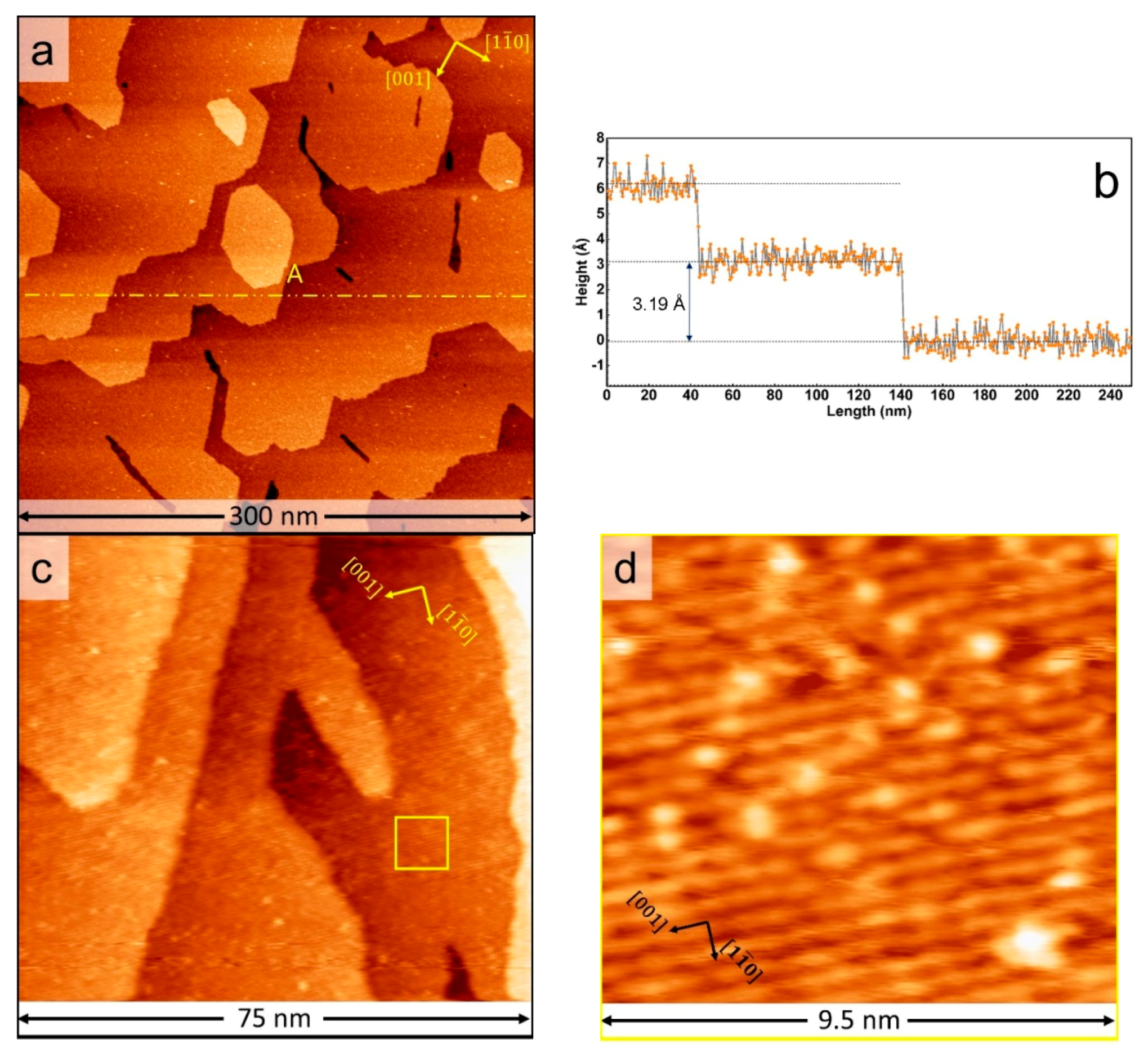
Figure 1. (a) Large-scale STM image of a clean TiO2(110) surface after sputtering and annealing in UHV at 900 K; sample voltage = +2.2 V, tunneling current = 150 pA. (b) Height along line A in Figure 1a shows the measured step height of clean TiO2(110) is 3.19 Å. (c) Zoom in of the TiO2(110) surface showing the alternating bright and dark rows characteristic of the (1 × 1) structure of slightly reduced rutile titania. (d) Zoom-in of the area denoted by the yellow square in Figure 1c.
Surfaces 03 00041 g001
Figure 2. (a) Large-scale STM image of Mo nanoparticles supported on TiO2(110) grown by physical vapor deposition at 300 K; sample voltage = +2.2 V, and tunneling current = 200 pA. The Mo coverage is 0.25 ML, as determined from XPS. (b) Measured height along the line marked A in Figure 2a. (c) Mo 3d XPS spectrum of the Mo nanoparticles supported on TiO2(110).
Surfaces 03 00041 g002
Figure 3. (a,b) Large-scale STM images of MoS2 slabs supported on TiO2(110) obtained with a sample voltage = +2.1 V and tunneling current = 150 pA. The coverage of Mo determined from XPS is 0.25 ML. (c) Zoomed-in STM image showing MoS2 slabs supported on TiO2(110). (d) Atom-resolved STM image of the “basal-bonded” MoS2 slab within the area marked by the yellow dotted square in Figure 3c. (e) Measured height along the line marked A in Figure 3c. (f) A (3 × 1) lattice superimposed on the “basal-bonded” MoS2 slabs in Figure 3c. The red dotted circles show the locations where the bright corner sites match the (3 × 1) lattice.
Surfaces 03 00041 g003
Figure 4. (a,b) STM images of MoS2 slabs supported on TiO2(110) obtained with a sample voltage = +2.2 V and tunneling current = 150 pA. The coverage of Mo determined from XPS is 0.49 ML. (c,d) MoS2 slabs supported on TiO2(110) obtained with a sample voltage = +2.2 V and tunneling current = 200 pA. The coverage of Mo determined from XPS is 0.61 ML.
Surfaces 03 00041 g004
Figure 5. (a) Measured height along the line marked B in Figure 3c over the elongated structures, (b) Zoom-in of an elongated structure at high contrast resolving rows of bright spots. The STM image is obtained with a sample voltage = +2.2 V and tunneling current = 400 pA. The coverage of Mo determined from XPS is 0.25 ML. (c) STM image showing the elongated structures formed as two to four rows.
Surfaces 03 00041 g005
Figure 6. Mo 3d and S 2p XPS spectra of MoS2 slabs supported on TiO2(110) at various initial coverages of Mo.
Surfaces 03 00041 g006
Figure 7. (a) Possible atomic model of the “basal-bonded” MoS2 slab supported on TiO2(110) with a (3 × 1) structure due to S adsorption. (b) Possible atomic model of “edge-on” MoSx stripes supported on TiO2(110), with a (3 × 1) structure, due to S adsorption.
Surfaces 03 00041 g007
Table 1. XPS binding energies for various components used for peak fitting.
ComponentsMo MetalMoOxMoO2MoS2
Binding energy (eV)228.0228.7229.8229.2
ΔBE * (eV)3.153.153.153.15
ComponentsMoSxS 2sS2− 2pS22− 2p
Binding energy (eV)228.3, 228.8226.2161.8163.1
ΔBE * (eV)3.15 1.161.16
* ΔBE(3d) = BE 3d5/2 − BE 3d3/2; ΔBE(2p) = BE 2p3/2 − BE 2p1/2.
Table 2. Ratio between various components of the XPS spectra in Figure 6.
Mo Coverage (ML)Mo:SMoS2:MoSxS2−:S22−
0.251:2.311:0.2411:0.329
0.491:2.221:0.0961:0.056
0.611:2.241:0.0931:0.062
Publisher’s Note: MDPI stays neutral with regard to jurisdictional claims in published maps and institutional affiliations.