Article

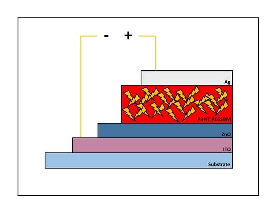
Stability of Non-Flexible vs. Flexible Inverted Bulk-Heterojunction Organic Solar Cells with ZnO as Electron Transport Layer Prepared by a Sol-Gel Spin Coating Method

by
Mohammad-Reza Zamani-Meymian
*,
Saeb Sheikholeslami
and
Milad Fallah
School of Physics, Iran University of Science and Technology, Tehran 1684613114, Iran
*
Author to whom correspondence should be addressed.
Surfaces 2020, 3(3), 319-327; https://doi.org/10.3390/surfaces3030023
Submission received: 21 May 2020 / Revised: 28 June 2020 / Accepted: 2 July 2020 / Published: 9 July 2020

Abstract

:
In this research, inverted bulk heterojunction organic solar cells (BHJ OSC) with poly(3-hexylthiophene-2,5-diyl): (6,6)-phenyl C61 butyric acid methyl (P3HT:PCBM) as the active layer were fabricated by a sol-gel spin coating method using flexible PET and non-flexible glass as substrates. The power conversion efficiency (PCE) and the stability of the cells were investigated. According to the results, the non-flexible device showed higher short circuit current (Jsc) as well as open-circuit voltage (Voc) as compared to the flexible one so that 2.52% and 0.67% PCE for non-flexible and flexible cells were obtained, respectively. From the stability point of view, the non-flexible device maintained 51% of its initial efficiency after six weeks in a dark atmosphere, while it was about 19% for the flexible cell after four weeks. The most important reason for the higher PCE with the higher stability in the non-flexible cell can be attributed to its higher shunt resistance (Rsh) and better interlayer connections at the electron collector side.

Graphical Abstract

1. Introduction

Since 1958 when the first organic solar cell (OSC) was fabricated by Calvin, the generation of renewable energy by OSCs has attracted much attention due to its advantages including cost-efficiency, intrinsic flexibility, semi-transparency, light-weight, environment-friendly composition, solution-based fabrication process, and roll-to-roll manufacturing. The efficiency, lifetime, and the cost are the most important subjects in the photovoltaics industry. Although OSCs are cheap in comparison to the dominant silicon solar cells, their efficiency and lifetime are challenges remaining ahead [1,2,3,4].
OSCs based on donor (D)−acceptor (A) materials are a kind of third-generation solar cells in which the organic polymer material acts as the light-absorbing layer. They are classified as: (i) organic bulk-heterojunction (BHJ) thin-film solar cells, (ii) organic tandem solar cells, and (iii) organic dye-sensitized solar cells, which makes them fit as a solar power source in space, building, automobile, gadget and memory device application [5,6]. Among the mentioned kinds of OSCs, although the maximum power conversion efficiency (PCE) of 17.3% was achieved in a tandem device till date, the BHJ structure is considered a more attractive structure than others due to the 3D interpenetrating network layer of D-A materials, resulting in enhanced p-n junctions in its active layer. During the past few years, rapid development on optimizing the active layer of BHJ OSC has been focused on facile functionalization of small molecule acceptors (SMA) like fullerenes and non-fullerenes with excellent tunability so that a ternary device of non-fullerene SMA with about 16.5% PCE made the BHJ OSC one step closer to industrialization [7,8,9,10,11,12,13,14].
Basically, in a regular BHJ OSC structure, a high work function material like transparent indium tin oxide (ITO) is usually used as the bottom electrode or anode, and poly(3,4-ethylenedioxythiophene) polystyrene sulfonate (PEDOT:PSS) is often applied as a buffer layer to transport holes. Moreover, the active layer is produced as by a mixed highly conducting polymer blend of D-polymers such as P3HT combined with A-molecules such as PCBM, as well as using Al, Mg, or Ca as the low work function metals for top electrode or cathode. In regular structure, absorption of photons by D-material results in generation and diffusion of excitons towards the D-A materials interface, followed by dissociation and transport of electrons and holes to cathode and anode, respectively. However, the PCE and the device stability under exposure to sunlight are still problems laying ahead in BHJ OSC [15,16,17,18].
To improve the stability of BHJ OSC it is important to understand the degradation factors which affect the device lifetime. Degradation at interfaces especially between ITO and PEDOT:PSS is one of the most problematic issues due to the hygroscopic and acidic nature of PEDOT:PSS that can corrode the surface of ITO, resulting in indium diffusion into photoactive layer and degradation of the device. Moreover, low work function metals as the cathode can easily be oxidized by oxygen. Infiltration of humidity and ultra-violet light influx to the active layers as well as thermal stresses can also decrease the lifetime of the device significantly [19,20,21].
Recently, the inverted structure has been highlighted for improving the stability of OSCs. In this structure, PEDOT:PSS which is an internal chemical reaction agent is removed or replaced with a transition metal oxides as a suitable alternatives for of the hole transporting layer (HTL). On the other hand, the devices in inverted configuration can use different materials as an electron transporting layer (ETL) such as ZnO, TiOx, Cs2CO3, or CsF2 for modifying the surface of ITO. Moreover, the inverted structure uses high work function metals for top electrodes such as Au or Ag that can be prepared by solution processing techniques which leads to manufacturing cost reduction [16,21,22]. Working principles in inverted BHJ OSCs can be described as follows: (i) absorption of photons in D material, resulting in the formation of excitons, (ii) migration of excitons towards the interface of D-A materials, (iii) dissociation and transport of electron-hole towards the appropriate electrodes via ETL and HTL, (iv) collection of electron and hole at the bottom and top electrodes, respectively [15,19].
The sol-gel spin coating method is the most commonly solution-based technique for fabrication of BHJ-OSCs thin films in inverted structures due to its advantages such as low cost, simplicity in fabrication, control of atomic-scale of materials, the capability of large area deposition at room temperature, control on the thickness and the capability of flexible thin films fabrication [23,24,25].
Different strategies have been developed to increase the stability of OSCs such as encapsulation, engineering of the active layer materials, using stable electrodes, employing inverted geometry, optimizing buffer layers, and especially the morphology engineering of active layer [26]. Dupuis et al. showed in their research that the structure of P3HT dramatically influenced the photodegradation process of P3HT thin films. Moreover, Wang et al. successfully presented an in-operando GISAXS measurement by which they prove that maintaining the nanomorphology of the BHJ layer can play an important role in final stability of inverted OSC [27,28,29]. Among the ETL materials, zinc oxide (ZnO) has been demonstrated as one of the most commonly used material especially for flexible and non-flexible inverted devices regarding its high electron mobility, high transparency across the visible spectral region, appropriate low work function, long-term stability and easy attainability by solution processing [30,31,32,33].
Although much research has been done on OSCs with flexible substrates, the time-dependence of its performance (stability) with flexible and non-flexible substrates has not been compared simultaneously. So, as the novelty of this research, inverted OSCs were fabricated via spin coating technique, consisting of (Ag/PCBM:P3HT/ZnO/ITO/PET or glass) as the flexible device (with PET) and as the non-flexible device (with glass). photovoltaic parameters and device stability of the prepared devices were investigated over time. Of course, it needs to be considered that the molecular weight of P3HT can affect the performance of the BHJ OSC [34,35,36], however, in this work, it was not the goal of the research so we avoid the effects of our P3HT’s molecular weight (Mn 54,000-75,000) which were similarly used in all samples.

2. Experimental

2.1. Chemicals & Materials

Zinc acetate dihydrate (Zn (O2CCH3)2), 99.5%, Merck Co., Darmstadt, Germany); 2-Methoxyethanol ((CH3OCH2CH2OH), 76.09 g/mol, 99.8%, Merck Co., Darmstadt, Germany); Monoethanolamine (C2H7NO, 61.08 g/mol, +98%, Merck Co., Darmstadt, Germany); P3HT (99.995%, Sigma Aldrich Co., St. Louis, MI, USA, Mn 54,000–75,000); PC61BM (99.5%, Sigma Aldrich Co., St. Louis, MI, USA); Dichlorobenzene (analytical grade, +99%, Sigma Aldrich Co., St. Louis, MI, USA); ITO-coated PET (Solaronix, Aubonne, Switzerland, sheet resistance of 14 Ω/sq); glass substrate (Isfahan Optics Industries, Isfahan, Iran, sheet resistance of 80 Ω/sq).

2.2. Synthesis

For the preparation of 0.75 M ZnO solution, 3.41 g of zinc acetate dihydrate (Zn (O2CCH3)2) was dissolved in 20 mL of 2-methoxyethanol, followed by adding 0.9 mL of monoethanolamine (C2H7NO) as stabilizer into the solution. The solution was slowly stirred for 60 min via a magnetic stir-bar mixer, then aged for 24 h to increase the strength of the solution against cracking during drying [37]. The as-deposited thin film was annealed in the atmosphere at 100 °C for 10 min. To prepare the active layer, a mixture of 50 mg P3HT as well as 50 mg PC61BM were dissolved in 2 mL of dichlorobenzene, followed by stirring at 50 °C for 24 h. The ITO-coated PET as well as glass were used as flexible and non-flexible substrates, respectively. PET-ITO was etched by acetone and the same process for glass-ITO was done by hydrochloric acid as well as nitric acid. Afterward, the substrates were rinsed by deionized water, then they dried at 100 °C for 10 min. All the etching and rinsing materials were purchased by Merc Co in analytical grades. The aged ZnO solution was deposited on PET-ITO and glass-ITO by a spin coating method (Backer Viera Trading Co. Tehran, Iran, model SC-410A) for 50 sec at 4000 rpm, followed by drying at 140 °C for 60 min in the atmosphere. Then a layer of P3HT:PC61BM was deposited on the ZnO layer by spin coating method for 30 sec at 1500 rpm. The samples were annealed at 120 °C in a vacuum chamber of 10−6 mbar for 20 min. Ultimately, a 50 nm layer of silver as the anode was deposited on P3HT:PC61BM layer by a thermal-PVD method. Figure 1 shows the energy level diagram of a typical BHJ OSC.

2.3. Analysis

The optical transmittance was measured by UV–vis spectrophotometer (UV-2100, Rayleigh, Beijing, China, wavelength range: 200–900 nm, wavelength accuracy: ±0.3 nm). The J-V diagram was obtained by a solar simulator (SIM-1030, IRASOL, Tehran, Iran, multiple LED source, wavelength range: 380–1000 nm) under AM 1.5 solar spectrum, equipped with a potentiostat (Em Stat2, PalmSens BV, Houten, The Netherlands). The light intensity was adjusted by a calibrated Si reference cell towards sunlight intensity of 80 mW/cm2.

3. Results and Discussion

Figure 2 presents the initial J-V curves of prepared solar cells with Jsc 11.35, Voc 0.60, FF 37 and PCE 2.52 for the non-flexible device, as well as Jsc 2.65, Voc 0.56, FF 45 and PCE 0.67 for the flexible one. The mechanism of calculation of PCE is considered as PCE = Jsc × Voc × FF/Pin, where Jsc is the short-circuit current density, Voc is the open-circuit voltage, FF is the fill factor, and Pin is the power density of the incident light of 100 mW/cm2 [8]. According to the figure, there is a difference of about 0.04 V between the open-circuit voltage (Voc) in flexible and non-flexible solar cells. One of the most important influential agents on Voc is the recombination rate of injected electrons [5]. The barriers against charge-transport will result in accumulation of carriers and increasing the series resistance, leading to more carrier recombination probability and decreasing the Voc. The tangent slope of the vertical part (near Voc) which is proportional to the reciprocal of series resistance (1/Rs) can be seen in J-V diagram of both non-flexible and flexible devices, leading to the difference between Rs as the transference resistance in flexible and non-flexible devices so that the steeper slope in the non-flexible device (with glass) against flexible device (with PET) can prove the higher Rs of the flexible device. This can be related to the trap states at the interface of PET-ITO/ZnO, leading to lower mobility in the flexible device which results in higher charge transfer resistance as well as higher probability of carrier recombination that can play an important role in decreasing of Voc as compared to the non-flexible device [38,39,40].
Moreover, the tangent slope of the transverse part (near Jsc) in J-V curve can be proportional to the reciprocal of shunt resistance (1/Rsh), so according to Figure 2, the steeper mentioned slope in the flexible device as compared to the non-flexible one can result in higher Rsh in the non-flexible device. Rsh is considered as a manufacturing defect based on poor solar cell design. It seems that the lattice defects on the surface of ITO during the cleaning process (cleaning by acetone-soaked cotton) can result in a more forward leakage path of carriers in the flexible cell as compared to the non-flexible one, so it can be concluded that the resistance of glass-ITO against degradation is more than the PET-ITO [40,41,42,43]. Of course, the morphological testing should be used for reliable decision making, however, according to the same materials and the same manufacturing steps for all samples, the difference in outcomes can possibly be related to the effects of substrates. Furthermore, using electrochemical impedance measurements to exact estimate the charge transference resistance can provide more exact information.
Figure 3 shows the optical transparency of ZnO thin film in which high optical transparency of ZnO is indicated. The transparency of 90% can transmit sunlight to the active layer at the desired level, and in this respect is not an obstacle to the entry of light.
Although the non-flexible solar cell reached a higher efficiency than the flexible one, its PCE is too low. This can be related to the annealing condition of this study in which ZnO thin film was annealed at the atmosphere, resulting in more oxygen penetration within the crystal lattice of ZnO. Oxygen can act as a barrier to electrical conductivity (electron absorber), so to eliminate this problem, annealing should be done in a vacuum or in a noble gas [24,44]. Of course, it should be considered that the vacuum annealing can result in lower transparency.
To measure the stability of solar cells, the J-V curves have been obtained in dark condition with an ambient atmosphere during six and four weeks for non-flexible and flexible cells, respectively. According to Figure 4 and Table 1, the PCE of the non-flexible cell remained nearly stable during the first two weeks. At the end of the third week, the PCE decreased to about 70% of initial PCE, which nearly remained constant during the next two weeks. Then it drops to about 50% of the initial PCE at the end of the sixth week. As it can be seen in Figure 4, the flexible cell demonstrated a dramatic decrease in PCE to about 45% during the first week and then dropped to about 36% of its initial value at the end of second week. It remained nearly stable in the next two weeks, followed by a reduction to about 20% of initial PCE at the end of the fourth week. As shown, the drop in the PCE of the cell with the PET substrate is much higher than the cell with the glass one which can be related to more desirable connections at the interface of glass-ITO/ZnO rather than PET-ITO/ZnO, resulting in more surface states at the interface of PET-ITO/ZnO that can act as recombination sites [45,46].

4. Conclusions

In the present work, the stability of inverted non-flexible (with glass substrate) and flexible (with PET substrate) solar cells with P3HT:PCBM as an active layer as well as ZnO thin film as the ETL were investigated. Power conversion efficiencies of 0.67% and 2.52% were achieved for flexible and non-flexible cells, respectively. The lower PCE of the flexible cell as compared to the non-flexible one could be related to the higher series resistance of the flexible solar cell. The creation of defects during the process in at the surface of ITO for flexible cell causes the increase of series resistance, resulting in a decrease of charge carrier mobility and Voc. Moreover, non-flexible cell showed more stability than the flexible one. The final efficiency of the non-flexible cell was reached about 51% of the initial value after 42 days, while it was about 19% of the initial value after 28 days for the flexible one. Given the significant potential and the hopeful path ahead of BHJ OSCs with non-fullerene SMA which have been shown in the researches, the results of this study could help as a way to improve the efficiency of OSCs based on non-fullerene SMA.

Author Contributions

Conceptualization, M.-R.Z.-M.; methodology, S.S. and M.F.; software, S.S.; validation, M.-R.Z.-M., S.S. and M.F.; formal analysis, S.S. and M.F.; investigation, S.S. and M.F.; resources, S.S.; data curation, M.-R.Z.-M. and M.F.; writing—original draft preparation, M.-R.Z.-M.; writing—review and editing, M.F.; visualization, M.F.; supervision, M.-R.Z.-M.; project administration, M.-R.Z.-M.; All authors have read and agreed to the published version of the manuscript.

Funding

This research received no external funding.

Conflicts of Interest

The authors declare no conflict of interest.

References

  1. Kim, D.J.; Kim, H.K. Optimization of titanium-doped indium oxide anodes for heterojunction organic solar cells. Phys. Stat. Solidi A 2016, 214, 1600463. [Google Scholar] [CrossRef]
  2. Mutlu, A.; Can, M.; Tozlu, C. Performance improvement of organic solar cell via incorporation of donor type self- assembled interfacial monolayer. Thin Solid Films 2019, 685, 88–96. [Google Scholar] [CrossRef]
  3. Khanmohammadi, K.; Sohrabi, B.; Zamani, M.R. Effect of electron-donating and -withdrawing substitutions in naphthoquinone sensitizers: The structure engineering of dyes for DSSC. J. Mol. Struct. 2018, 1167, 274–279. [Google Scholar] [CrossRef]
  4. Konstantinova, E.A.; Vorontsov, A.S.; Forsh, P.A. Investigation of Photoelectron Properties of Polymer Films with Silicon Nanoparticles. Surfaces 2019, 2, 387–394. [Google Scholar] [CrossRef] [Green Version]
  5. Fallah, M.; Maleki, I.; Zamani-Meymian, M.R.; Abdi, Y. Enhancing the efficiency of dye-sensitized solar cell by increasing the light trapping and decreasing the electron-hole recombination rate due to Ag@TiO2 core-shell photoanode structure. Mater. Res. Express 2019, 7, 016409. [Google Scholar] [CrossRef]
  6. Hussain, C.M. Handbook of Nanomaterials for Industrial Applications, 1st ed.; Elsevier: Amsterdam, The Netherlands, 2018. [Google Scholar]
  7. Ramki, K.; Venkatesh, N.; Sathiyan, G.; Thangamuthu, R.; Sakthivel, P. A comprehensive review on the reasons behind low power conversion efficiency of dibenzo derivatives based donors in bulk heterojunction organic solar cells. Org. Electron. 2019, 73, 182–204. [Google Scholar] [CrossRef]
  8. Meng, L.; Zhang, Y.; Wan, X.; Li, C.; Zhang, X.; Wang, Y.; Ke, X.; Xiao, Z.; Ding, L.; Xia, R.; et al. Organic and solution-processed tandem solar cells with 17.3% efficiency. Science 2018, 361, 1094–1098. [Google Scholar] [CrossRef] [Green Version]
  9. Zhao, W.; Li, S.; Yao, H.; Zhang, S.; Zhang, Y.; Yang, B.; Hou, J. Molecular Optimization Enables over 13% Efficiency in Organic Solar Cells. J. Am. Chem. Soc. 2017, 139, 7148–7151. [Google Scholar] [CrossRef]
  10. Ye, L.; Li, S.; Liu, X.; Zhang, S.; Ghasemi, M.; Xiong, Y.; Hou, J.; Ade, H. Quenching to the percolation Threshold in Organic Solar Cells. Joule 2019, 3, 443–458. [Google Scholar] [CrossRef] [Green Version]
  11. Chen, T.W.; Peng, K.K.; Lin, Y.W.; Su, Y.J.; Ma, K.J.; Hong, L.; Chang, C.C.; Hou, J.; Hsu, C.S. A chlorinated nonacyclic carbazole-based acceptor affords over 15% efficiency in organic solar cells. J. Mat. Chem. A 2020, 8, 1131–1137. [Google Scholar] [CrossRef]
  12. Jiang, K.; Wei, Q.; Lai, J.Y.L.; Peng, Z.; Kim, H.K.; Yuan, J.; Ye, L.; Ade, H.; Zou, Y.; Yan, H. Alkyl Chain Tuning of Small Molecule Acceptors for Efficient Organic Solar Cells. Joule 2019, 3, 3020–3033. [Google Scholar] [CrossRef]
  13. Zhang, G.; Zhao, J.; Chow, P.C.Y.; Jiang, K.; Zhang, J.; Zhu, Z.; Zhang, J.; Huang, F.; Yan, H. Nonfullerene Acceptor Molecules for Bulk Heterojunction Organic Solar Cells. Chem. Rev. 2018, 118, 3447–3507. [Google Scholar] [CrossRef] [PubMed]
  14. Zhang, J.; Tan, H.S.; Guo, X.; Facchetti, A.; Yan, H. Material insights and challenges for non-fullerene organic solar cells based on small molecular acceptors. Nat. Energy 2018, 3, 720–731. [Google Scholar] [CrossRef]
  15. Souza, F.L.D.; Leite, E. Nanoenergy: Nanotechnology Applied for Energy Production, 2nd ed.; Springer International Publishing: Amsterdam, The Netherlands, 2018. [Google Scholar] [CrossRef]
  16. Rwenyagila, E.R. A Review of Organic Photovoltaic Energy Source and Its Technological Designs. Int. J. Photoenergy 2017, 1656512. [Google Scholar] [CrossRef]
  17. Ram, K.S.; Singh, J. Highly Efficient and Stable Solar Cells with Hybrid of Nanostructures and Bulk Heterojunction Organic Semiconductors. Adv. Theory Simul. 2019, 2, 1900030. [Google Scholar] [CrossRef]
  18. Wu, W.; Zhang, J.; Shen, W.; Zhong, M.; Guo, S. Graphene Quantum Dots Band Structure Tuned by Size for Efficient Organic Solar Cells. Phys. Stat. Solidi A 2019, 216, 1900657. [Google Scholar] [CrossRef]
  19. Rafique, S.; Abdullah, S.M.; Sulaiman, K.; Iwamoto, M. Fundamentals of bulk heterojunction organic solar cells: An overview of stability/degradation issues and strategies for improvement Renew. Sust. Energy Rev. 2018, 84, 43–53. [Google Scholar] [CrossRef]
  20. Shafket, R.; Doan, V.V.; Lee, H.K.; Lee, S.K.; Lee, J.C.; Moon, S.J.; So, W.W.; Song, C.E.; Shin, W.S. Enhanced photostability in polymer solar cells achieved with modified electron transport layer. Thin Solid Films 2019, 669, 42–48. [Google Scholar] [CrossRef]
  21. Gupta, S.K.; Banerjee, S.; Singh, A.; Pali, L.S.; Garg, A. Modeling of degradation in normal and inverted OSC devices. Sol. Energy Mat. Sol. Cells 2019, 191, 329–338. [Google Scholar] [CrossRef]
  22. Chander, N.; Singh, S.; Iyer, S.S.K. Stability and reliability of P3HT:PC61BM inverted organic solar cells. Sol. Energy Mat. Sol. Cells 2017, 161, 407–415. [Google Scholar] [CrossRef]
  23. Aslan, F.; Adam, G.; Stadler, P.; Goktas, A.; Mutlu, I.H.; Sariciftci, N.S. Sol–gel derived In2S3 buffer layers for inverted organic photovoltaic cells. Sol. Energy 2014, 108, 230–237. [Google Scholar] [CrossRef]
  24. Fallah, M.; Zamani-Meymian, M.R.; Rabbani, M. Influence of two gradual steps of vacuum annealing on structural and opto-electronic characteristics of Nb-doped TiO2 transparent conducting oxide. Superlattice Microst. 2018, 123, 242–250. [Google Scholar] [CrossRef]
  25. Chu, A.K.; Tien, W.C.; Lai, S.W.; Tsai, H.L.; Bai, R.Y.; Lin, X.Z.; Chen, L.Y. High-resistivity sol-gel ITO thin film as an interfacial buffer layer for bulk heterojunction organic solar cells. Org. Electron. 2017, 46, 99–104. [Google Scholar] [CrossRef]
  26. Cheng, P.; Zhan, X. Stability of organic solar cells: Challenges and strategies. Chem. Soc. Rev. 2016, 45, 2544–2582. [Google Scholar] [CrossRef] [PubMed]
  27. Wang, W.; Schaffer, C.J.; Song, L.; Körstgens, V.; Pröller, S.; Indari, E.D.; Wang, T.; Abdelsamie, A.; Bernstorff, S.; Müller-Buschbaum, P. In-Operando Morphology Investigation of Inverted Bulk Heterojunction Organic Solar Cells with GISAXS. J. Mater. Chem. A 2015, 3, 8324–8331. [Google Scholar] [CrossRef]
  28. Dupuis, A.; Tournebize, A.; Bussiere, P.O.; Rivaton, A.; Gardette, J.L. Morphology and photochemical stability of P3HT:PCBM active layers of organic solar cells. Eur. Phys. J. Appl. Phys. 2011, 56, 34104. [Google Scholar] [CrossRef] [Green Version]
  29. Wang, W.; Guo, S.; Herzig, E.M.; Sarkar, K.; Schindler, M.; Magerl, D.; Philipp, M.; Perlich, J.; Müller-Buschbaum, P. Investigation of Morphological Degradation of P3HT:PCBM Bulk Heterojunction Films Exposed to Long-Term Host Solvent Vapor. J. Mater. Chem. A 2016, 4, 3743–3753. [Google Scholar] [CrossRef] [Green Version]
  30. Sahdan, M.Z.; Malek, M.F.; Alias, M.S.; Kamaruddin, S.A.; Norhidayah, C.A.; Sarip, N.; Nafarizal, N.; Rusop, M. Fabrication of inverted bulk heterojunction organic solar cells basedon conjugated P3HT:PCBM using various thicknesses of ZnO bufferlayer. Optik 2015, 126, 645–648. [Google Scholar] [CrossRef] [Green Version]
  31. Sarkar, K.; Braden, E.V.; Bonke, S.A.; Bach, U.; Mìller-Buschbaum, P. Screen-Printing of ZnO Nanostructures from Sol–Gel Solutions for Their Application in Dye-Sensitized Solar Cells. Chem. Sus. Chem. 2015, 8, 2696–2704. [Google Scholar] [CrossRef]
  32. Guerrero, A.; Garcia-Belmonte, G. Recent Advances to Understand Morphology Stability of Organic Photovoltaics. Nano-Micro Lett. 2017, 9, 10–25. [Google Scholar] [CrossRef] [Green Version]
  33. You, H.; Zhang, J.; Zhang, C.; Lin, Z.; Chen, D.; Chang, J.; Zhang, J. Efficient flexible inverted small-bandgap organic solar cells with low-temperature zinc oxide interlayer. Jpn. J. Appl. Phys. 2016, 55, 122302. [Google Scholar] [CrossRef]
  34. Liu, F.; Chen, D.; Wang, C.; Luo, K.; Gu, W.; Briseno, A.L.; Hsu, J.W.P.; Russell, T.P. Molecular Weight Dependence of the Morphology in P3HT: PCBM Solar Cells. ACS Appl. Mater. Interfaces 2014, 6, 19876–19887. [Google Scholar] [CrossRef] [PubMed]
  35. Holmes, N.P.; Ulum, S.; Sista, P.; Burke, K.B.; Wilson, M.G.; Stefan, M.C.; Zhou, X.; Dastoor, P.C.; Belcher, W.J. The effect of polymer molecular weight on P3HT: PCBM nanoparticulate organic photovoltaic device performance. Sol. Energy Mater Sol. 2014, 128, 369–377. [Google Scholar] [CrossRef]
  36. Spoltore, D.; Vangerven, T.; Verstappen, P.; Piersimoni, F.; Bertho, S.; Vandewal, K.; Brande, N.V.D.; Mele, B.V.; Sio, A.D.; Parisi, J.; et al. Effect of molecular weight on morphology and photovoltaic 4 properties in P3HT:PCBM solar cells. Org. Electron. 2015, 21, 160–170. [Google Scholar] [CrossRef]
  37. Fallah, M.; Zamani-Meymian, M.-R.; Rahimi, R.; Rabbani, M. Effect of annealing treatment on electrical and optical properties of Nb doped TiO2thin films as a TCO prepared by sol–gel spin coating method. Appl. Surf. Sci. 2014, 316, 456–462. [Google Scholar] [CrossRef]
  38. Khorami, A.; Joodaki, M. Extracting voltage-dependent series resistance of single diode model for organic solar cells. SN Appl. Sci. 2019, 1, 619. [Google Scholar] [CrossRef] [Green Version]
  39. Zellmeier, M.; Kuhnapfel, S.; Rech, B.; Nickel, N.H.; Rappich, J. Enhanced stability of P3HT/poly-crystalline Si thin film hybrid solar cells. Phys. Stat. Solidi A 2016, 213, 1904–1908. [Google Scholar] [CrossRef]
  40. Yang, R.Y.; Chen, H.Y.; Lai, F.D. Performance Degradation of Dye-Sensitized Solar Cells Induced by Electrolytes. Adv. Mat. Sci. Eng. 2012, 902146. [Google Scholar] [CrossRef] [Green Version]
  41. Schrecongost, D.; Aziziha, M.; Zhang, H.T.; Tung, I.C.; Tessmer, J.; Dai, W.; Wang, Q.; Engel-Herbert, R.; Wen, H.; Picard, Y.N. On-Demand Nanoscale Manipulations of Correlated Oxide Phases. Adv. Funct. Mater. 2019, 26, 1905585. [Google Scholar] [CrossRef]
  42. Proctor, C.M.; Nguyen, T.Q. Effect of leakage current and shunt resistance on the light intensity dependence of organic solar cells. Appl. Phys. Lett. 2015, 106, 083301. [Google Scholar] [CrossRef]
  43. Ríos-Ramirez, B.; Nair, P.K. On the Stability of Operation of Antimony Sulfide Selenide Thin Film Solar Cells Under Solar Radiation. Phys. Stat. Solidi A 2018, 215, 1800479. [Google Scholar] [CrossRef]
  44. Polo, A.; Lhermitte, C.R.; Dozzi, M.V.; Selli, E.; Sivula, K. Hydrogenation of ZnFe2O4 Flat Films: Effects of the Pre-Annealing Temperature on the Photoanodes Efficiency for Water Oxidation. Surfaces 2020, 3, 93–104. [Google Scholar] [CrossRef] [Green Version]
  45. Koide, N.; Islam, A.; Chiba, Y.; Han, L. Improvement of efficiency of dye-sensitized solar cells based on analysis of equivalent circuit. J. Photochem. Photobiol. A Chem. 2006, 182, 296–305. [Google Scholar] [CrossRef]
  46. Girardi, L.; Bardini, L.; Michieli, N.; Kalinic, B.; Maurizio, C.; Rizzi, G.A.; Mattei, G. Co3O4 Nanopetals on Si as Photoanodes for the Oxidation of Organics. Surfaces 2019, 2, 41–53. [Google Scholar] [CrossRef] [Green Version]
Figure 1. Energy level diagram of prepared inverted BHJ OSC.
Surfaces 03 00023 g001
Figure 2. Initial J-V curves of flexible and non-flexible solar cells.
Surfaces 03 00023 g002
Figure 3. Optical transparency of ZnO thin film.
Surfaces 03 00023 g003
Figure 4. Stability of flexible and non-flexible solar cells after four and six weeks, respectively.
Surfaces 03 00023 g004
Table 1. Stability of photovoltaic parameters of flexible and non-flexible solar cells over time. All the devices were fabricated in an area of 1cm2.
DayJsc (mA.cm−2)Voc (V)FF (%)PCE (%)
GlassPETGlassPETGlassPETGlassPET
011.35 ± 0.562.65 ± 0.750.60 ± 0.010.56 ± 0.0137 ± 0.01645 ± 0.0192.52 ± 0.170.67 ± 0.20
710.44 ± 0.531.68 ± 0.320.60 ± 0.010.53 ± 0.0237 ± 0.02333 ± 0.0252.32 ± 0.160.30 ± 0.07
1410.25 ± 0.481.37 ± 0.430.58 ± 0.020.53 ± 0.0137 ± 0.01333 ± 0.0132.20 ± 0.180.24 ± 0.08
218.23 ± 0.430.96 ± 0.140.57 ± 0.010.53 ± 0.0137 ± 0.01933 ± 0.0271.74 ± 0.130.17 ± 0.3
287.63 ± 0.400.75 ± 0.280.57 ± 0.020.52 ± 0.0137 ± 0.02033 ± 0.0161.61 ± 0.250.13 ± 0.05
357.32 ± 0.43 0.56 ± 0.01 35 ± 0.026 1.43 ± 0.13
426.95 ± 0.39 0.52 ± 0.01 36 ± 0.017 1.30 ± 0.1

