Surface Functionalization of Magnetic Nanoparticles Using a Thiol-Based Grafting-Through Approach


Abstract
1. Introduction
2. Materials and Methods
2.1. Instruments
2.2. Materials
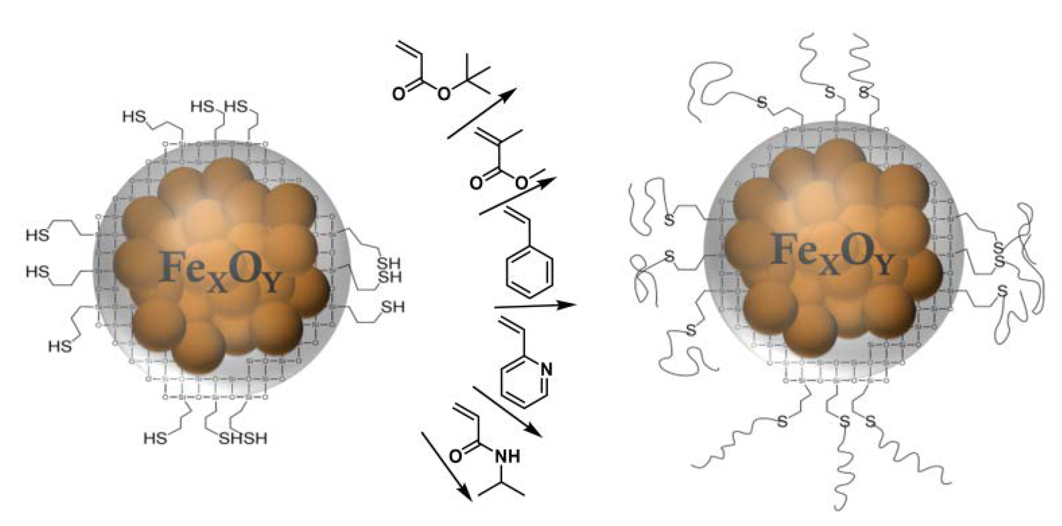
2.3. Synthesis
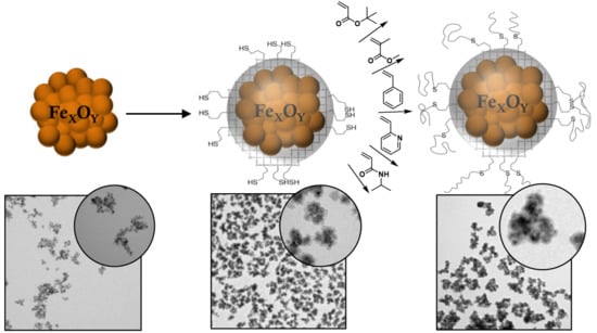
3. Results and Discussion
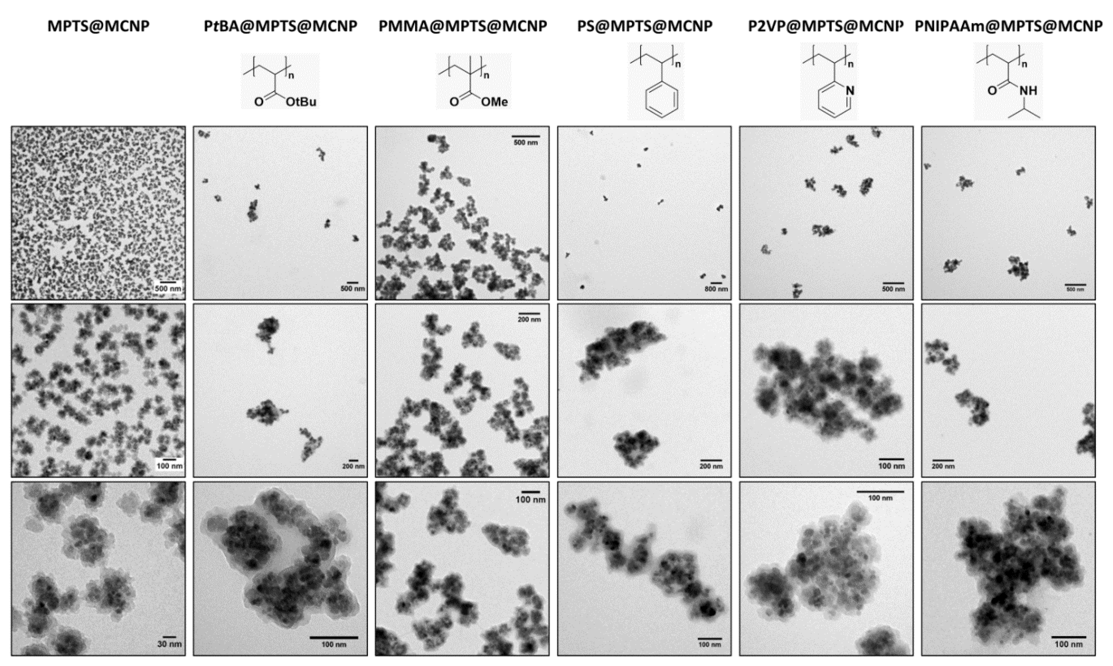
3.1. MPTS@MCNP
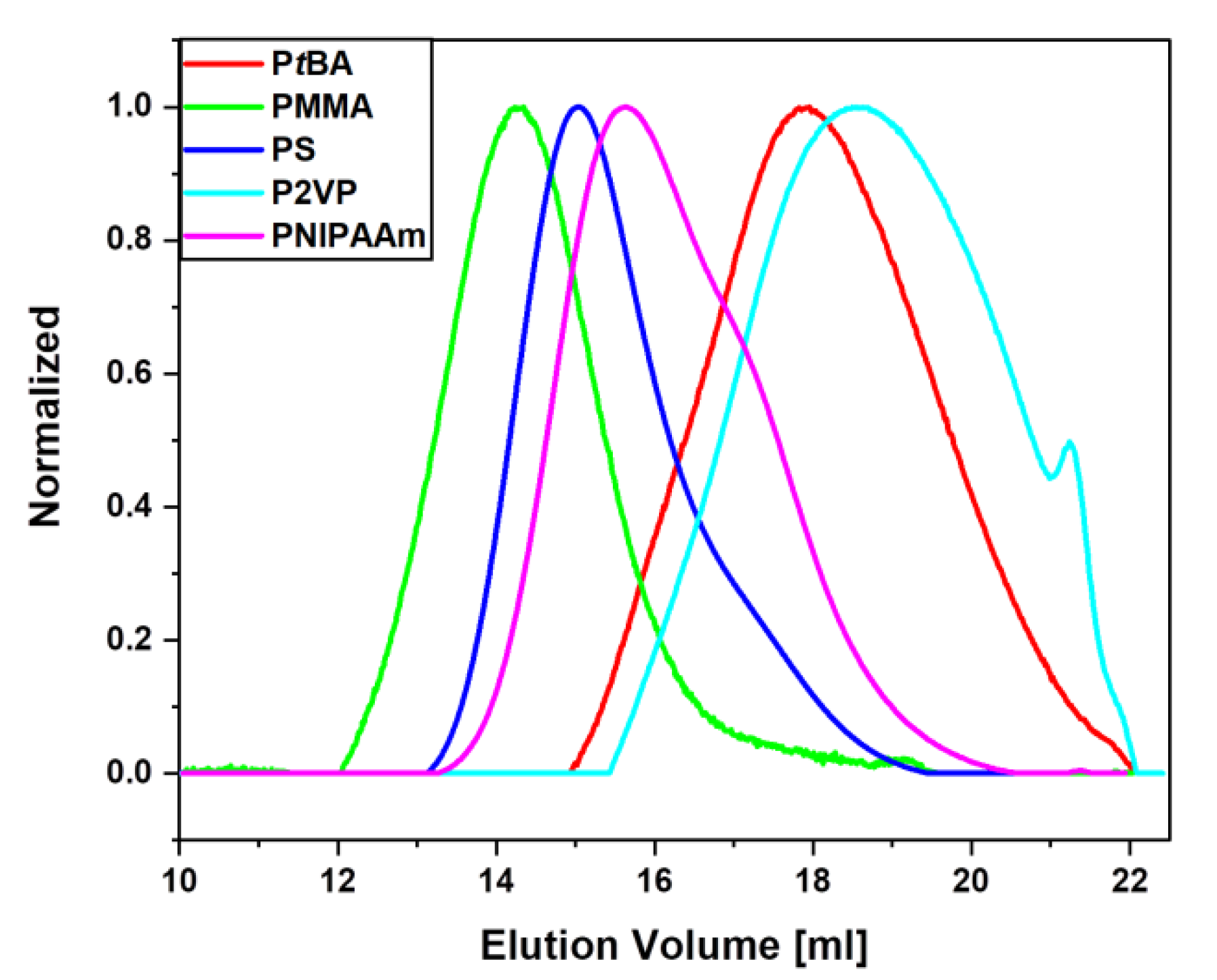
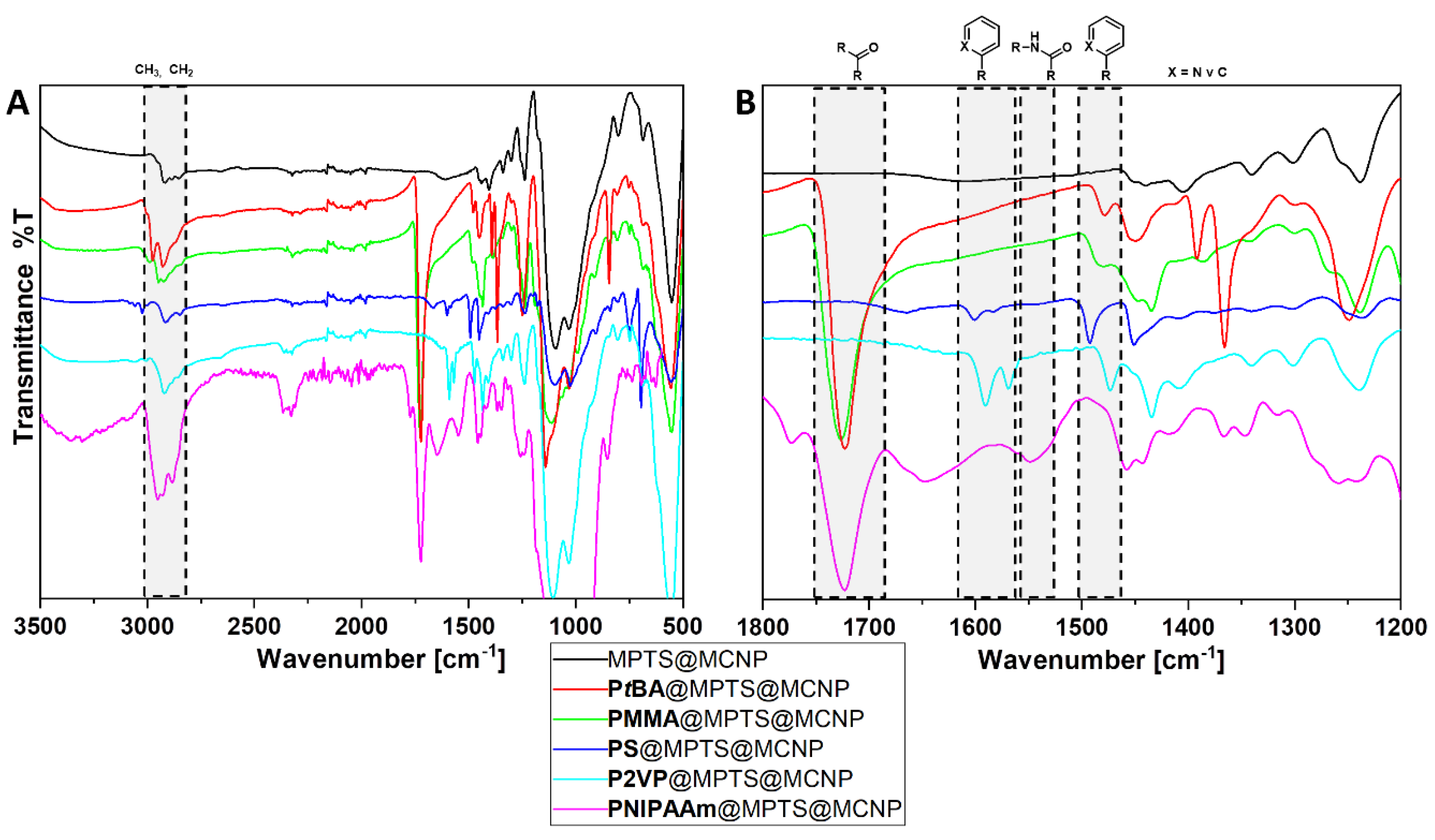
3.2. Polymer@MPTS@MCNP
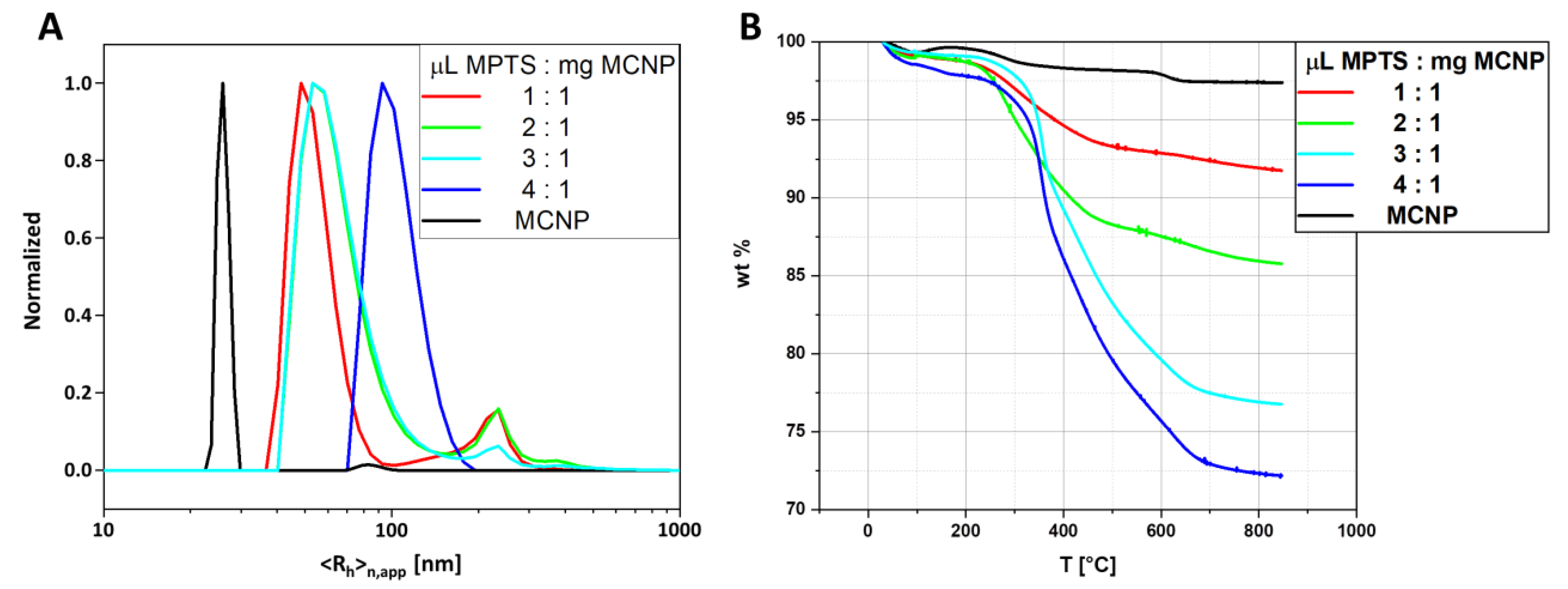
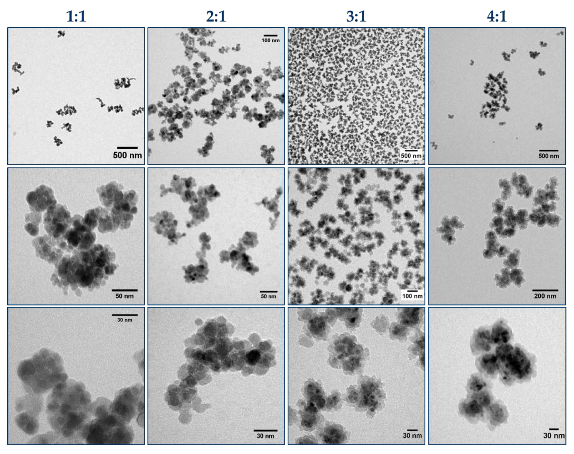
3.3. Influence of Particle Concentration on the Polymerization
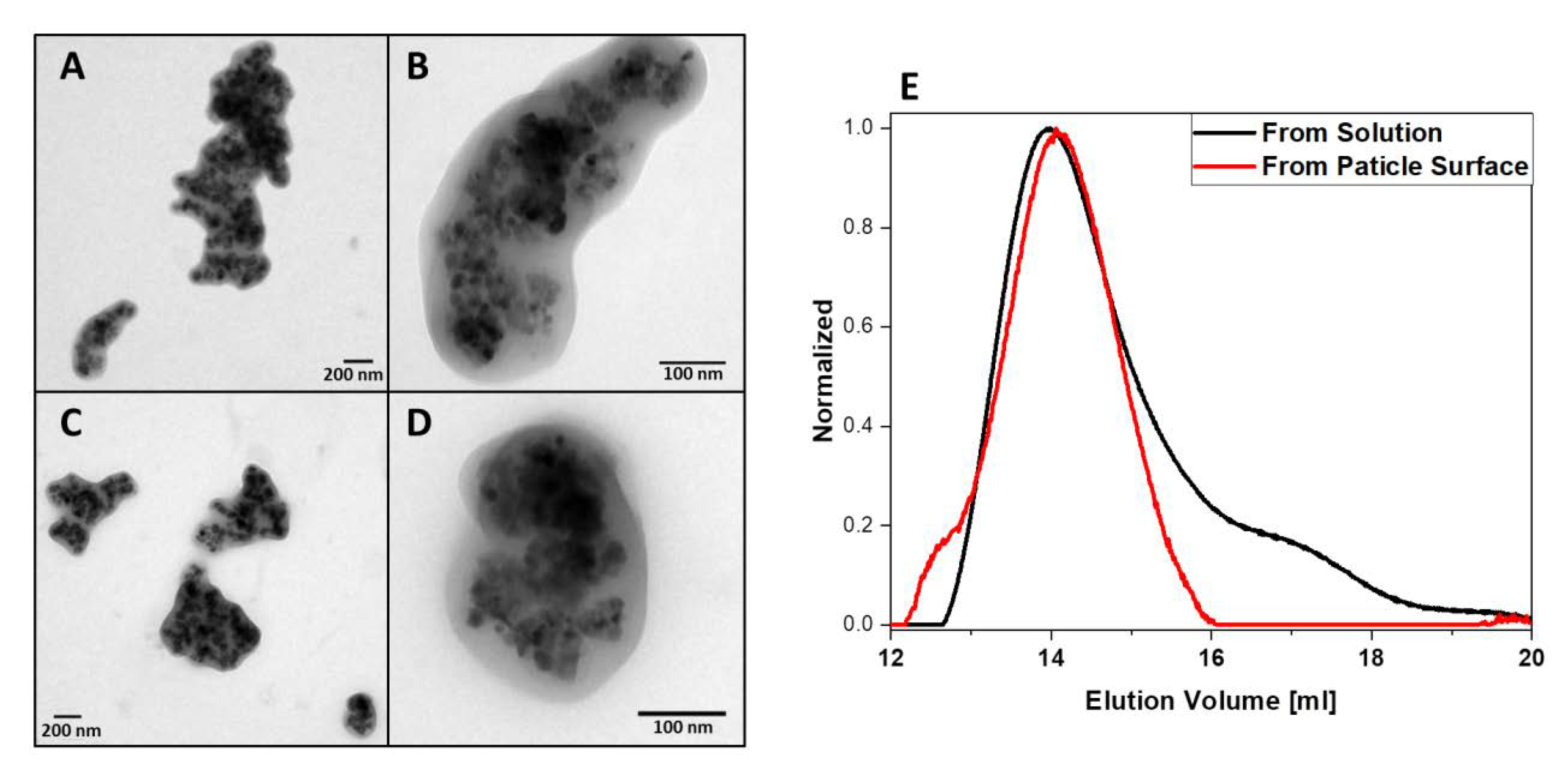
3.4. Comparison of Polymer Formed at the Nanoparticle Surface vs. in Solution
4. Conclusions
Supplementary Materials
Author Contributions
Funding
Acknowledgments
Conflicts of Interest
References
- Ito, A.; Shinkai, M.; Honda, H.; Kobayashi, T. Medical Application of Functionalized Magnetic Nanoparticles. J. Biosci. Bioeng. 2005, 100, 1–11. [Google Scholar] [CrossRef] [PubMed]
- Song, L.; Ho, V.H.B.; Chen, C.; Yang, Z.; Liu, D.; Chen, R.; Zhou, D. Efficient, pH-Triggered Drug Delivery Using a pH-Responsive DNA-Conjugated Gold Nanoparticle. Adv. Healthc. Mater. 2013, 2, 275–280. [Google Scholar] [CrossRef] [PubMed]
- Mochalin, V.N.; Pentecost, A.; Li, X.-M.; Neitzel, I.; Nelson, M.; Wei, C.; He, T.; Guo, F.; Gogotsi, Y. Adsorption of Drugs on Nanodiamond: Toward Development of a Drug Delivery Platform. Mol. Pharm. 2013, 10, 3728–3735. [Google Scholar] [CrossRef]
- Hergt, R.; Dutz, S.; Müller, R.; Zeisberger, M. Magnetic Particle Hyperthermia: Nanoparticle Magnetism and Materials Development for Cancer Therapy. J. Phys. Condens. Matter 2006, 18, S2919–S2934. [Google Scholar] [CrossRef]
- Chen, Y.; Xiong, Z.; Zhang, L.; Zhao, J.; Zhang, Q.; Peng, L.; Zhang, W.; Ye, M.; Zou, H. Facile Synthesis of Zwitterionic Polymer-Coated Core-Shell Magnetic Nanoparticles for Highly Specific Capture of N-Linked Glycopeptides. Nanoscale 2015, 7, 3100–3108. [Google Scholar] [CrossRef]
- Yeh, C.-H.; Chen, S.-H.; Li, D.-T.; Lin, H.-P.; Huang, H.-J.; Chang, C.-I.; Shih, W.-L.; Chern, C.-L.; Shi, F.-K.; Hsu, J.-L. Magnetic Bead-Based Hydrophilic Interaction Liquid Chromatography for Glycopeptide Enrichments. J. Chromatogr. A 2012, 1224, 70–78. [Google Scholar] [CrossRef]
- Urena-Benavides, E.E.; Lin, E.L.; Foster, E.L.; Xue, Z.; Ortiz, M.R.; Fei, Y.; Larsen, E.S.; Kmetz, A.A., II; Lyon, B.A.; Moaseri, E.; et al. Low Adsorption of Magnetite Nanoparticles with Uniform Polyelectrolyte Coatings in Concentrated Brine on Model Silica and Sandstone. Ind. Eng. Chem. Res. 2016, 55, 1522–1532. [Google Scholar] [CrossRef]
- Yagub, M.T.; Sen, T.K.; Afroze, S.; Ang, H.M. Dye and its Removal from Aqueous Solution by Adsorption: A Review. Adv. Colloid Interface Sci. 2014, 209, 172–184. [Google Scholar] [CrossRef]
- Ozay, O.; Ekici, S.; Baran, Y.; Kubilay, S.; Aktas, N.; Sahiner, N. Utilization of Magnetic Hydrogels in the Separation of Toxic Metal Ions from Aqueous Environments. Desalination 2010, 260, 57–64. [Google Scholar] [CrossRef]
- Dutta, K.; De, S. Smart Responsive Materials for Water Purification: An Overview. J. Mater. Chem. A 2017, 5, 22095–22112. [Google Scholar] [CrossRef]
- Fidale, L.C.; Nikolajski, M.; Rudolph, T.; Dutz, S.; Schacher, F.H.; Heinze, T. Hybrid Fe3O4@Amino Cellulose Nanoparticles in Organic Media–Heterogeneous Ligands for Atom Transfer Radical Polymerizations. J. Colloid Interface Sci. 2013, 390, 25–33. [Google Scholar] [CrossRef] [PubMed]
- Stevens, P.D.; Fan, J.; Gardimalla, H.M.R.; Yen, M.; Gao, Y. Superparamagnetic Nanoparticle-Supported Catalysis of Suzuki Cross-Coupling Reactions. Org. Lett. 2005, 7, 2085–2088. [Google Scholar] [CrossRef]
- Cai, J.; Miao, Y.Q.; Yu, B.Z.; Ma, P.; Li, L.; Fan, H.M. Large-Scale, Facile Transfer of Oleic Acid-Stabilized Iron Oxide Nanoparticles to the Aqueous Phase for Biological Applications. Langmuir 2017, 33, 1662–1669. [Google Scholar] [CrossRef] [PubMed]
- Billing, M.; Gräfe, C.; Saal, A.; Biehl, P.; Clement, J.H.; Dutz, S.; Weidner, S.; Schacher, F.H. Zwitterionic Iron Oxide (γ-Fe2O3) Nanoparticles Based on P(2VP-grad-AA) Copolymers. Macromol. Rapid Commun. 2017, 38, 1600637. [Google Scholar] [CrossRef] [PubMed]
- Zhao, T.; Chen, K.; Gu, H. Investigations on the Interactions of Proteins with Polyampholyte-Coated Magnetite Nanoparticles. J. Phys. Chem. B 2013, 117, 14129–14135. [Google Scholar] [CrossRef]
- Debnath, K.; Mandal, K.; Jana, N.R. Phase Transfer and Surface Functionalization of Hydrophobic Nanoparticle using Amphiphilic Poly(amino acid). Langmuir 2016. [Google Scholar] [CrossRef]
- Von der Lühe, M.; Günther, U.; Weidner, A.; Grafe, C.; Clement, J.H.; Dutz, S.; Schacher, F.H. SPION@Polydehydroalanine Hybrid Particles. RSC Adv. 2015, 5, 31920–31929. [Google Scholar] [CrossRef]
- Keefe, A.J.; Jiang, S. Poly(zwitterionic)protein Conjugates Offer Increased Stability without Sacrificing Binding Affinity or Bioactivity. Nat. Chem. 2012, 4, 59–63. [Google Scholar] [CrossRef]
- Gong, Y.-K.; Winnik, F.M. Strategies in Biomimetic Surface Engineering of Nanoparticles for Biomedical Applications. Nanoscale 2012, 4, 360–368. [Google Scholar] [CrossRef]
- Mazzucchelli, S.; Colombo, M.; De Palma, C.; Salvade, A.; Verderio, P.; Coghi, M.D.; Clementi, E.; Tortora, P.; Corsi, F.; Prosperi, D. Single-Domain Protein A-Engineered Magnetic Nanoparticles: Toward a Universal Strategy to Site-Specific Labeling of Antibodies for Targeted Detection of Tumor Cells. ACS Nano 2010, 4, 5693–5702. [Google Scholar] [CrossRef]
- Biehl, P.; von der Lühe, M.; Dutz, S.; Schacher, F.H. Synthesis, Characterization, and Applications of Magnetic Nanoparticles Featuring Polyzwitterionic Coatings. Polymers 2018, 10, 91. [Google Scholar] [CrossRef] [PubMed]
- McCarthy, S.A.; Davies, G.-L.; Gun’ko, Y.K. Preparation of Multifunctional Nanoparticles and their Assemblies. Nat. Protoc. 2012, 7, 1677–1693. [Google Scholar] [CrossRef] [PubMed]
- Kumar, R.; Roy, I.; Ohulchanskyy, T.Y.; Goswami, L.N.; Bonoiu, A.C.; Bergey, E.J.; Tramposch, K.M.; Maitra, A.; Prasad, P.N. Covalently Dye-Linked, Surface-Controlled, and Bioconjugated Organically Modified Silica Nanoparticles as Targeted Probes for Optical Imaging. ACS Nano 2008, 2, 449–456. [Google Scholar] [CrossRef] [PubMed]
- Chekina, N.; Horak, D.; Jendelova, P.; Trchova, M.; Benes, M.J.; Hruby, M.; Herynek, V.; Turnovcova, K.; Sykova, E. Fluorescent Magnetic Nanoparticles for Biomedical Applications. J. Mater. Chem. 2011, 21, 7630–7639. [Google Scholar] [CrossRef]
- Kyeong, S.; Jeong, C.; Kim, H.Y.; Hwang, D.W.; Kang, H.; Yang, J.-K.; Lee, D.S.; Jun, B.-H.; Lee, Y.-S. Fabrication of Mono-Dispersed Silica-Coated Quantum Dot-Assembled Magnetic Nanoparticles. RSC Adv. 2015, 5, 32072–32077. [Google Scholar] [CrossRef]
- Cui, Y.; Zheng, X.-S.; Ren, B.; Wang, R.; Zhang, J.; Xia, N.-S.; Tian, Z.-Q. Au@Organosilica Multifunctional Nanoparticles for the Multimodal Imaging. Chem. Sci. 2011, 2, 1463–1469. [Google Scholar] [CrossRef]
- Chiefari, J.; Chong, Y.K.; Ercole, F.; Krstina, J.; Jeffery, J.; Le, T.P.T.; Mayadunne, R.T.A.; Meijs, G.F.; Moad, C.L.; Moad, G.; et al. Living Free-Radical Polymerization by Reversible Addition−Fragmentation Chain Transfer: The RAFT Process. Macromolecules 1998, 31, 5559–5562. [Google Scholar] [CrossRef]
- O’Brien, N.; McKee, A.; Sherrington, D.C.; Slark, A.T.; Titterton, A. Facile, Versatile and Cost Effective Route to Branched Vinyl Polymers. Polymer 2000, 41, 6027–6031. [Google Scholar] [CrossRef]
- Eckardt, O.; Wenn, B.; Biehl, P.; Junkers, T.; Schacher, F.H. Facile Photo-Flow Synthesis of Branched Poly(butyl acrylate)s. React. Chem. Eng. 2017, 2, 479–486. [Google Scholar] [CrossRef]
- Zhou, F.; Liu, W.; Chen, M.; Sun, D.C. A Novel Way to Prepare Ultra-Thin Polymer Films Through Surface Radical Chain-Transfer Reaction. Chem. Commun. 2001, 2446–2447. [Google Scholar] [CrossRef]
- Wang, S.; Zhou, Y.; Guan, W.; Ding, B. One-Step Copolymerization Modified Magnetic Nanoparticles via Surface Chain Transfer Free Radical Polymerization. Appl. Surf. Sci. 2008, 254, 5170–5174. [Google Scholar] [CrossRef]
- Chen, J.-J.; Struk, K.N.; Brennan, A.B. Surface Modification of Silicate Glass Using 3-(Mercaptopropyl)trimethoxysilane for Thiol–Ene Polymerization. Langmuir 2011, 27, 13754–13761. [Google Scholar] [CrossRef] [PubMed]
- Bach, L.G.; Islam, M.R.; Kim, J.T.; Seo, S.; Lim, K.T. Encapsulation of Fe3O4 Magnetic Nanoparticles with Poly(methyl methacrylate) via Surface Functionalized Thiol-Lactam Initiated Radical Polymerization. Appl. Surf. Sci. 2012, 258, 2959–2966. [Google Scholar] [CrossRef]
- Liu, P.; Liu, W.M.; Xue, Q.J. In Situ Radical Transfer Addition Polymerization of Styrene from Silica Nanoparticles. Eur. Polym. J. 2004, 40, 267–271. [Google Scholar] [CrossRef]
- Liu, S.; Zhou, F.; Di, D.; Jiang, S. Surface-Confined Radical Chain Transfer: The Intermediate Reaction for Chemically Attaching Polymer Films on Porous Silica for Chromatographic Application. Colloids Surf. A Physicochem. Eng. Asp. 2004, 244, 87–93. [Google Scholar] [CrossRef]
- Dutz, S.; Clement, J.H.; Eberbeck, D.; Gelbrich, T.; Hergt, R.; Müller, R.; Wotschadlo, J.; Zeisberger, M. Ferrofluids of Magnetic Multicore Nanoparticles for Biomedical Applications. J. Magn. Magn. Mater. 2009, 321, 1501–1504. [Google Scholar] [CrossRef]
- Dutz, S.; Andrä, W.; Hergt, R.; Müller, R.; Oestreich, C.; Schmidt, C.; Töpfer, J.; Zeisberger, M.; Bellemann, M.E. Influence of Dextran Coating on the Magnetic Behaviour of Iron Oxide Nanoparticles. J. Magn. Magn. Mater. 2007, 311, 51–54. [Google Scholar] [CrossRef]
- Lu, A.-H.; Salabas, E.L.; Schüth, F. Magnetic Nanoparticles: Synthesis, Protection, Functionalization, and Application. Angew. Chem. Int. Ed. 2007, 46, 1222–1244. [Google Scholar] [CrossRef]
- Tong, S.; Quinto, C.A.; Zhang, L.; Mohindra, P.; Bao, G. Size-Dependent Heating of Magnetic Iron Oxide Nanoparticles. ACS Nano 2017. [Google Scholar] [CrossRef]
- Gao, J.; Gu, H.; Xu, B. Multifunctional Magnetic Nanoparticles: Design, Synthesis, and Biomedical Applications. Acc. Chem. Res. 2009, 42, 1097–1107. [Google Scholar] [CrossRef]
- Rho, W.-Y.; Kim, H.-M.; Kyeong, S.; Kang, Y.-L.; Kim, D.-H.; Kang, H.; Jeong, C.; Kim, D.-E.; Lee, Y.-S.; Jun, B.-H. Facile Synthesis of Monodispersed Silica-Coated Magnetic Nanoparticles. J. Ind. Eng. Chem. 2014, 20, 2646–2649. [Google Scholar] [CrossRef]
- Vogt, C.; Toprak, M.S.; Muhammed, M.; Laurent, S.; Bridot, J.-L.; Müller, R.N. High Quality and Tuneable Silica Shell–Magnetic Core Nanoparticles. J. Nanopart. Res. 2010, 12, 1137–1147. [Google Scholar] [CrossRef]
- Yi, D.K.; Selvan, S.T.; Lee, S.S.; Papaefthymiou, G.C.; Kundaliya, D.; Ying, J.Y. Silica-Coated Nanocomposites of Magnetic Nanoparticles and Quantum Dots. J. Am. Chem. Soc. 2005, 127, 4990–4991. [Google Scholar] [CrossRef] [PubMed]
- Viltužnik, B.; Košak, A.; Zub, Y.L.; Lobnik, A. Removal of Pb(II) Ions from Aqueous Systems using Thiol-Functionalized Cobalt-Ferrite Magnetic Nanoparticles. J. Sol-Gel Sci. Technol 2013, 68, 365–373. [Google Scholar] [CrossRef]
- Shahverdi, N.; Heydarinasab, A.; Panahi, H.A.; Moniri, E. Synthesis and Evaluation of Enalapril-Loaded PVA/PMC Modified Magnetic Nanoparticles as a Novel Efficient Nano-Carrier. Chem. Sel. 2019, 4, 5246–5250. [Google Scholar] [CrossRef]
- Forster, D.J.; Heuts, J.P.A.; Davis, T.P. Conventional and Catalytic Chain Transfer in the Free-Radical Polymerization of 2-Phenoxyethyl Methacrylate. Polymer 2000, 41, 1385–1390. [Google Scholar] [CrossRef]
- Eckardt, O.; Seupel, S.; Festag, G.; Gottschaldt, M.; Schacher, F.H. Synthesis and Degradation of Branched, Photo-Labile Poly(acrylic acid) and Polystyrene. Polym. Chem. 2019, 10, 593–602. [Google Scholar] [CrossRef]


| Monomer | Molar Ratios | Monomer/MPTS@MCNP | (kg mol−1) | Ð | |
|---|---|---|---|---|---|
| Monomer | TPO | ||||
| tBA | 74 | 0.06 | 6.15 g/10 mg | 8.900 (a) | 2.2 (a) |
| MMA | 74 | 0.06 | 4.8 g/10 mg | 141.200 (a) | 2.1 (a) |
| Styrene | 74 | 0.06 | 5 g/10 mg | 58.500 (b) | 1.9 (b) |
| P2VP | 74 | 0.06 | 5.05 g/10 mg | 5.600 (b) | 2.3 (b) |
| NIPAAm | 74 | 0.06 | 5.43 g/10 mg | 35.400 (a) | 2.0 (a) |
| Sample | wt Loss (%) | <Rh>n,app max (nm) | Calculated Polymer Shell Thickness (nm) |
|---|---|---|---|
| MPTS@MCNP | 23.2 | 51 | |
| PtBA@MPTS@MCNP | 44.3 (Δ = 21.1) | 174 | 14 (a) |
| PMMA@MPTS@MCNP | 54.3 (Δ = 31.1) | 224 | 19 (a) |
| PS@MPTS@MCNP | 49.3 (Δ = 26.1) | 206 | 17 (a) |
| P2VP@MPTS@MCNP | 52.0 (Δ = 28.8) | 224 | 18 (a) |
| PNIPAAm@MPTS@MCNP | 34.1 (Δ = 10.9) | 190 | 7 (a) |
| Band Assignment | Wavenumbers in cm−1 Surface Coating | ||||
|---|---|---|---|---|---|
| PtBA | PMMA | PS | P2VP | PNIPAAm | |
| νas (CH3, CH2) | 2975 ms | 2993 m | - | 2926 s | 2953 s |
| νas (CH3, CH2) | 2924 ms | 2950 ms | 2912 m | 2336 w | 2882 s |
| ν (C=O) | 1722 s | 1725 s | - | - | 1721 s |
| δ (CO–N–H) | - | - | - | - | 1549 m |
| ν (C–C in–ring) | - | - | 1603 w | 1591 m/1569 s | - |
| ν (C–C in–ring) | - | - | 1493 ms/1451 ms | 1473 ms | - |
| MPTS@MCNP (mg) | (a) (kg mol−1) | Ð (a) |
|---|---|---|
| 5 | 6.900 | 9.6 |
| 10 | 12.800 | 5.2 |
| 20 | 13.300 | 4.5 |
| 50 | 62.600 | 2.8 |
© 2020 by the authors. Licensee MDPI, Basel, Switzerland. This article is an open access article distributed under the terms and conditions of the Creative Commons Attribution (CC BY) license (http://creativecommons.org/licenses/by/4.0/).
Share and Cite
Biehl, P.; Schacher, F.H. Surface Functionalization of Magnetic Nanoparticles Using a Thiol-Based Grafting-Through Approach. Surfaces 2020, 3, 116-131. https://doi.org/10.3390/surfaces3010011
Biehl P, Schacher FH. Surface Functionalization of Magnetic Nanoparticles Using a Thiol-Based Grafting-Through Approach. Surfaces. 2020; 3(1):116-131. https://doi.org/10.3390/surfaces3010011
Chicago/Turabian StyleBiehl, Philip, and Felix H. Schacher. 2020. "Surface Functionalization of Magnetic Nanoparticles Using a Thiol-Based Grafting-Through Approach" Surfaces 3, no. 1: 116-131. https://doi.org/10.3390/surfaces3010011
APA StyleBiehl, P., & Schacher, F. H. (2020). Surface Functionalization of Magnetic Nanoparticles Using a Thiol-Based Grafting-Through Approach. Surfaces, 3(1), 116-131. https://doi.org/10.3390/surfaces3010011