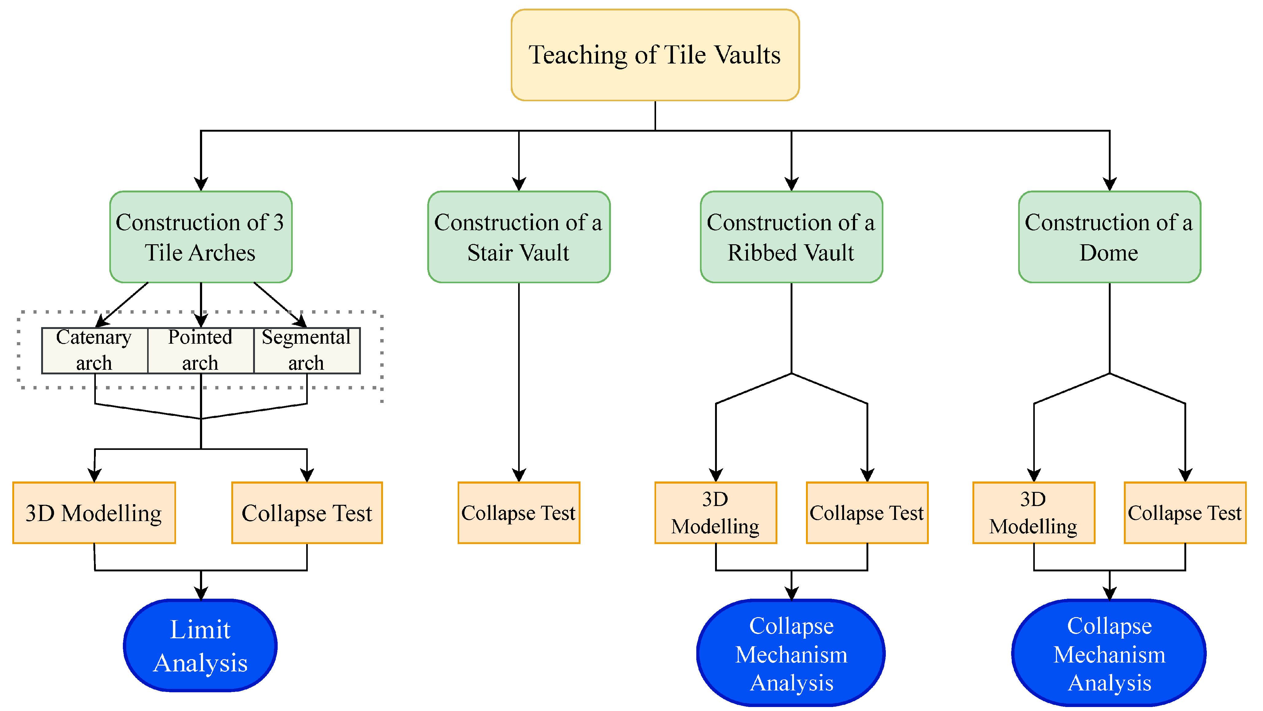
3.1. Construction of Arches
Thirteen students were enrolled in the course. In their first steps, in groups of three to four, students are tasked with designing and building four different arches: a segmental arch, a catenary arch, a pointed arch and a three-centered basket-handle arch. These are representative geometries that encompass different curvature types, described in the work carried out by Huerta [
23], which provides a comprehensive analysis of traditional masonry structures. These geometries can be easily plotted using simple resources: a chain, a cord and a marker. The dimensions resulting from the use of cardboard sheets as drawing templates for each arch are detailed in
Table 1.
Before building the arches, the students prepared cardboard centerings by arranging the shape in two parallel planes with a separation slightly less than the length of the bricks. Between these two pieces of cardboard, they placed a zigzag strip of cardboard to maintain the separation between the parallel planes, sticking them in place with glue and tape (
Figure 4a). Two bricks were laid below the centering to facilitate their posterior removal.
Although the aim of this workshop is not to train students as bricklayers, they actively engage in the construction process under appropriate guidance. By doing so, they gain direct, hands-on experience that reinforces their understanding far beyond what passive observation or theoretical explanation can achieve.
The act of building becomes their first meaningful encounter with the preparation and mechanical behavior of gypsum paste, offering a tangible and memorable foundation for structural learning. The gypsum paste is prepared by pouring water into a rubber tub, onto which the powdered gypsum is evenly sprinkled across the surface. The addition continues until the powder begins to emerge above the water level, ensuring that the resulting mixture has a fluid consistency to favor adherence with the brick pieces. Due to the rapid setting of the gypsum paste, they are instructed not to prepare large quantities so that all the paste produced can be used. The gypsum paste is taken as needed without stirring the mixture because it would accelerate the setting process. This would make the prepared gypsum difficult to work with and could lead to its disposal instead of use.
During the workshop, students are encouraged to try their hand at all the tasks involved: preparing gypsum paste, spreading some gypsum onto the bricks, and laying the brick pieces, yet as the course advances they tend to perform the tasks they are most proficient at more often.
In the present workshop, the masonry models are intentionally simplified and lack many of the features of real masonry construction, precisely to highlight these assumptions and allow students to observe their consequences. By contrast, actual structures may involve additional factors, such as backing at the haunches or adjacent masonry, that go beyond this idealized framework. In order to reproduce the behavior of fixed supports in the arch models, each springing was built on a flat base and bonded with gypsum, so that the arch was rigidly connected to it. In addition, a rope tie was installed between the two bases, preventing any relative separation. As a result, horizontal and vertical displacements, as well as rotations at the supports, were restrained, approximating the conditions of a fully fixed arch, as shown in
Figure 4b.
According to the technique described above, students begin by laying a first course of flat-laid bricks to complete the arch profile. A second course is then added, with staggered joints, using bricks that have been previously soaked in water to delay the setting of the gypsum. Additionally, a generous amount of gypsum is applied to the bricks before placing them in the second course. Each unit is pressed firmly into position to ensure proper adhesion and bonding with the underlying layer. Despite the rapid initial setting of the plaster, the centering was not removed until 24 h after application.
It should be mentioned that the basket-handle arch did not resist the centering removal. In this way, the students were able to verify the hypothesis of the line of thrusts inside the arch. The low resistance of the gypsum made by the students may also have contributed to this. Taking advantage of this, students are taught that to ensure that the thrust line remains within the arch, the spandrels should be filled up to a suitable height.
3.2. Collapse Tests on Arches
The objective of the collapse tests on arches was to verify that, by using affordable materials and a fundamental comprehension of the collapse mechanisms, an approximate value of the plastic moment capacity () could be determined for each arch geometry. To achieve this goal, careful geometric documentation was required prior to loading, so that the subsequent analysis could be supported by accurate records of the arches in their initial state.
Following removal of the centering, a series of photographs was taken to generate a three-dimensional model for each of the arches using photogrammetry, allowing further documentation and analysis. To define the profiles of the arches before the collapse test as accurately as possible for subsequent two-dimensional analysis, the photographs were taken from viewpoints surrounding the front face of each arch. Six different QR codes were placed on each arch to improve image recognition and restitution. 20 photographs were taken of the segmental arch, 15 of the catenary arch, and 13 for the pointed arch.
The photographs were taken using the rear camera of an iPhone SE (2nd generation), with an aperture of f/1.8, an exposure time of 1/160 s, ISO sensitivity of 125, and a focal length of 4 mm. The resolution of the photographs was 4032 × 3024 pixels.
The 3D models of the arches were generated using photogrammetry based on the selected image sets. The reconstruction process was carried out with Meshroom (version 2023.3.0), an open-source photogrammetry software based on the AliceVision framework [
24]. The software automatically processed the input photographs through a standard pipeline. The process begins with feature extraction, where the software identifies keypoints (e.g., Scale-Invariant Feature Transform descriptors) in each image. This is followed by feature matching, which establishes correspondences between overlapping images. Using these correspondences, Meshroom performs Structure-from-Motion (SfM) to estimate the internal and external camera parameters and reconstruct a sparse 3D point cloud that defines the scene geometry. The next step involves depth map computation and depth map fusion, which generate a dense point cloud by estimating pixel-level depth information across multiple views. Subsequently, a meshing algorithm converts the dense cloud into a triangular surface mesh, and an optional texturing stage applies image-based textures to the surface using a weighted blending approach. The final outputs of the pipeline also include a camera calibration data and orientation parameter file, and a reconstruction log for reproducibility and diagnostic purposes. Default settings were used for most steps, as the goal was to obtain an accurate geometric representation of the arch profile for subsequent two-dimensional structural analysis.
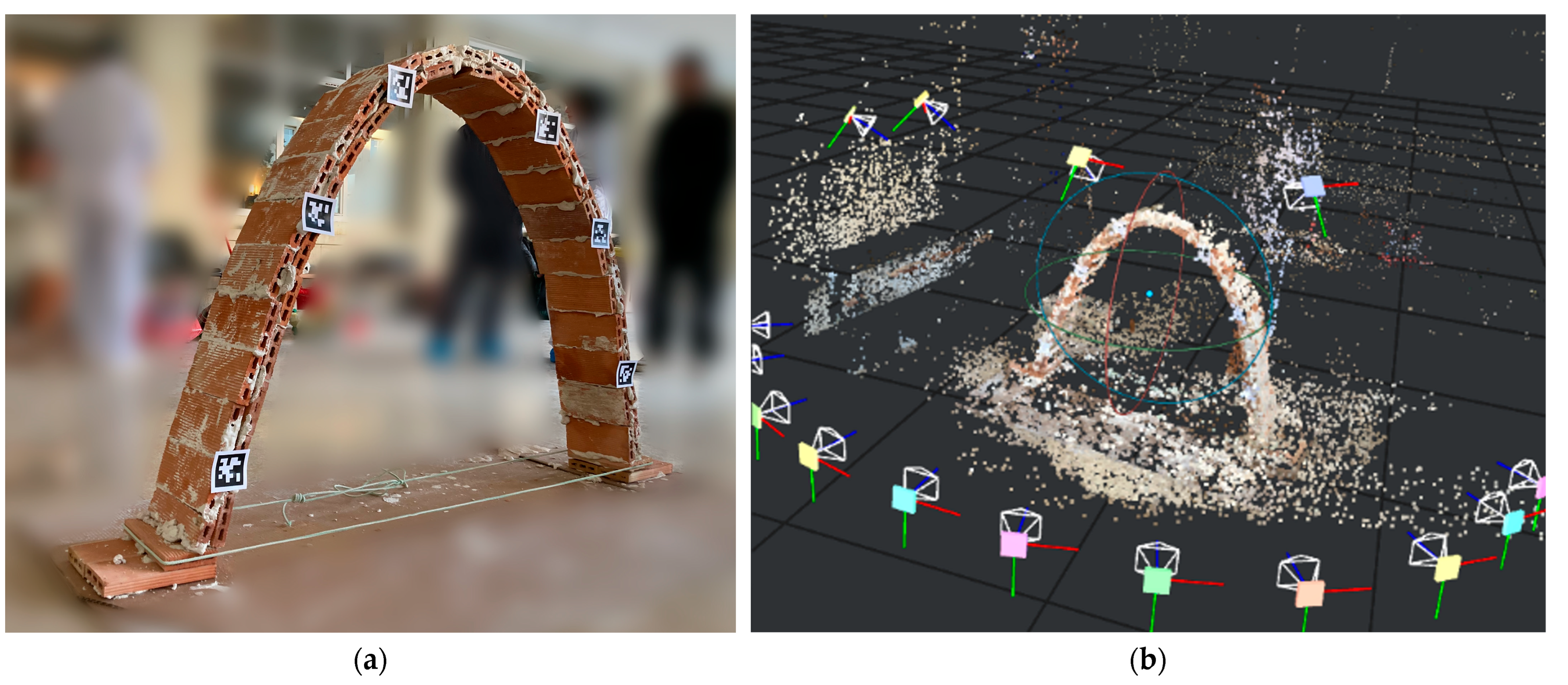
Figure 5a presents one of the photographs used in the photogrammetric reconstruction of the catenary arch.
Figure 5b shows the resulting sparse point cloud and the estimated camera positions generated by Meshroom during the Structure-from-Motion stage. The distribution of camera positions reflects the front-facing approach adopted during image acquisition, which was specifically intended to capture the geometry of the arch for two-dimensional analysis.
A 3D model of each arch was obtained in OBJ format, including texture mapping, which allows for direct visualization of the object in standard 3D environments. While this file can be optimized using Blender (version 4.4) to reduce its size prior to export, in this case the cleaning process was carried out in Rhinoceros. From Blender, the model was simply exported in FBX format.
Within Rhinoceros, the mesh was converted into polysurfaces using the MeshToNURB command, making it possible to perform geometric operations. Unnecessary geometry was trimmed to produce a simplified version of the vault (note that this process can be computationally intensive; for greater efficiency, it is advisable to clean the mesh in Blender prior to NURBS conversion). A vertical section was then generated by intersecting the polysurface with a reference plane, in order to extract a two-dimensional drawing of the arch. To improve visibility and eliminate background geometry, a ClippingPlane was introduced.
Once the 2D profile was isolated, it was refined on a new layer. Dimensional measurements were taken directly from this drawing and compared with those recorded immediately after the removal of the centering, to verify consistency in geometry.
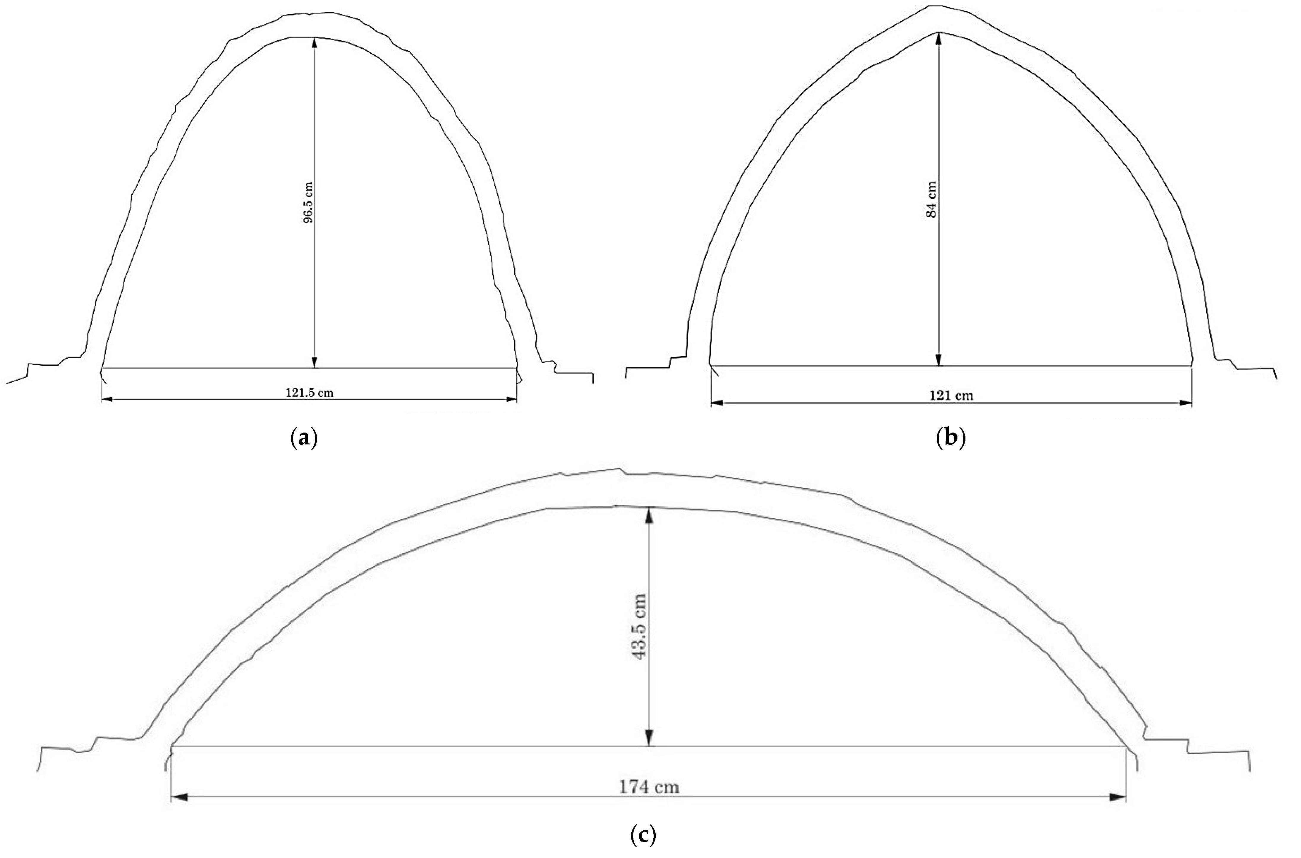
Figure 6 shows the 2D profile obtained of the catenary, pointed and segmental arches.
To conduct the collapse tests, the arches were loaded incrementally by placing gypsum sacks or thermo-clay blocks on the crown until collapse occurred. Although simplified, this procedure provides a straightforward and controlled method for introducing vertical loads. It enables students to grasp the progressive increase in horizontal thrust indirectly, by observing the visible consequences: the displacement of the line of thrust outside the masonry profile and the eventual formation of plastic hinges. The method is particularly suitable in a didactic context, as it avoids the complexity of distributed loading systems while still reproducing the essential structural response of the arch under increasing load.
Each test was documented with video recordings using the same camera device employed for photogrammetry, mounted on a tripod positioned two meters away directly in front of the arch at approximately mid-height. The resolution was 1920 × 1080 pixels, and the frame rate was 30 fps. These videos were subsequently analyzed to track the motion of individual pieces during the formation of the collapse mechanism. For this purpose, Tracker (version 6.3.2), a video analysis and modeling tool, was used. Although originally developed for physics education, this open-source software is well-suited for structural analysis applications involving motion tracking [
25].
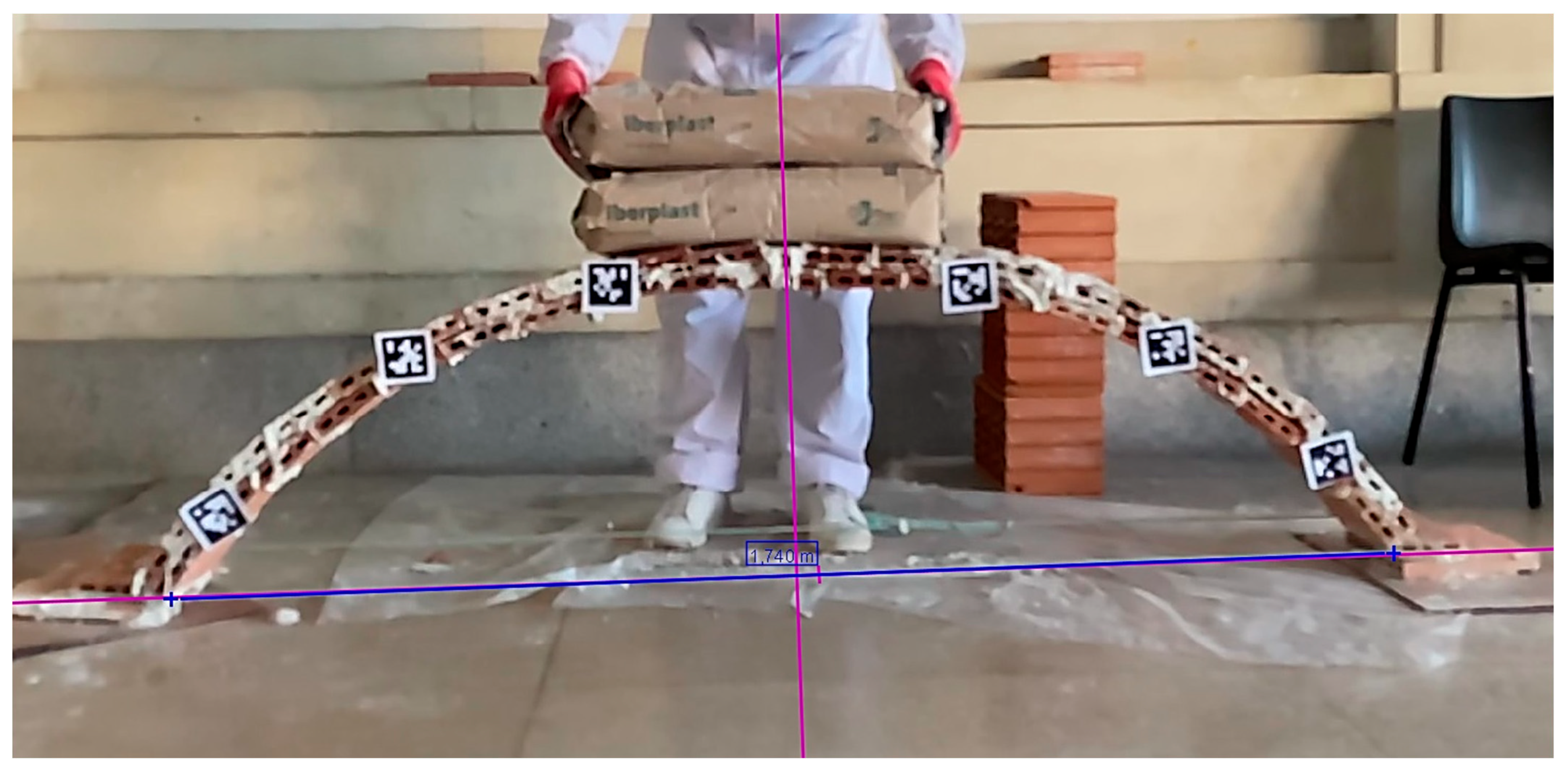
First, a reference axis system was set, and the arc length measurement is assigned as a reference for the scale in measuring movements.
Figure 7 shows the frame of the segmental arch used for the calibration of the geometric parameters.
As noted above, the arch was constructed with fixed support at both ends, making it a degree-3 indeterminate structure. Consequently, the development of a collapse mechanism requires the formation of four plastic hinges, which indeed occurred at the onset of failure, thereby confirming the fixed-end boundary conditions. This understanding is key for the proper practical differentiation between crack patterns that merely constitute three-hinged arches and configurations in which a fourth hinge appears that signal imminent collapse. In the experiments, the four hinges required for collapse appeared almost simultaneously. Nevertheless, it could be perceived that the hinges near the springings and at the crown tended to initiate slightly earlier, before the complete collapse mechanism was established.
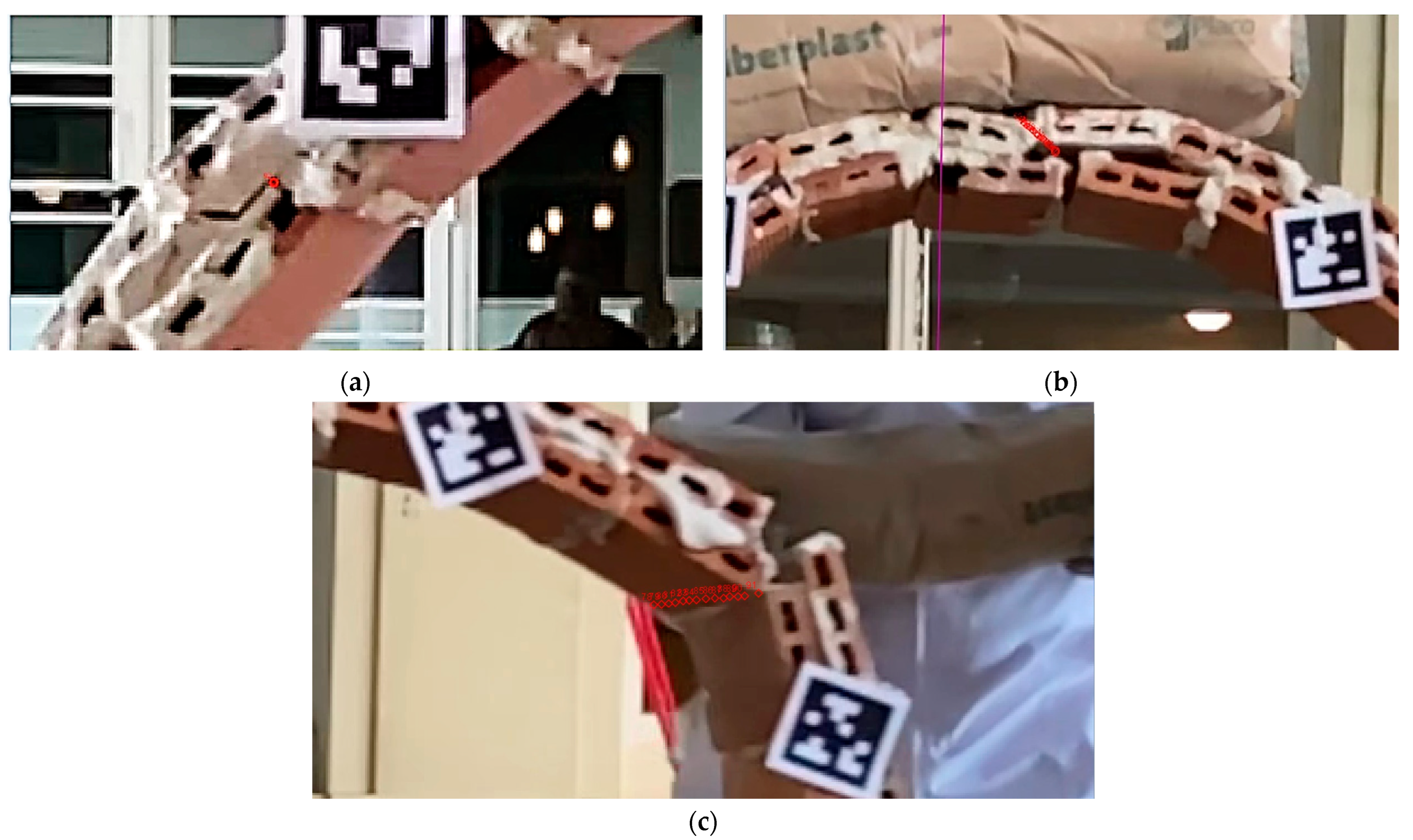
The pieces into which the structure is divided when it collapses move as a rigid solid, so that any point, including the hinges, rotates around the instantaneous axis of rotation. The two hinges located at the springings acted as rotational joints in the collapse, where no translational displacement was detected and only relative rotation occurred between the adjoining rigid blocks. In contrast, the other two hinges exhibited both rotational and translational movements. Most hinges were identified at the midline of the arch as shown in
Figure 8a (small red circle). The hinge displayed in
Figure 8b was also located in the midline of the arch. Its positions in successive frames are shown in the row of small red circles superimposed on the initial frame. In contrast, the hinge illustrated in
Figure 8c was formed very close to the intrados, completely separating the bricks from the extrados from the outset as required by the principle of compatibility of movements.
Collapse analysis under plastic theory is purely a matter of geometry and load distribution. The limit state is reached when a sufficient number of plastic-like hinges, corresponding here to cracks or joints opening, forms to create a kinematically admissible mechanism.
The principle of virtual work states that, for a system in equilibrium, the total external work done by the
n applied loads during a virtual displacement compatible with the constraints is exactly equal to the total internal work developed by the internal forces over the corresponding virtual deformations:
In the context of plastic analysis, the kinematic approach is adopted, whereby a plausible collapse mechanism is assumed. The external work is obtained as the sum, over all applied loads, of the scalar product of each force
and its corresponding virtual displacement
in the assumed collapse mechanism. The internal work is computed as the sum, over all plastic hinges, of the scalar product of the plastic moment capacity
and the hinge rotation
:
The principle of virtual work is an effective tool within this framework for estimating the ultimate load in masonry arches. By varying the position of the hinges, the load at which equilibrium is lost can be determined. Hinge locations can be visually identified and measured during the experiment, thus allowing students to determine the plastic moment capacity from the observed behavior.
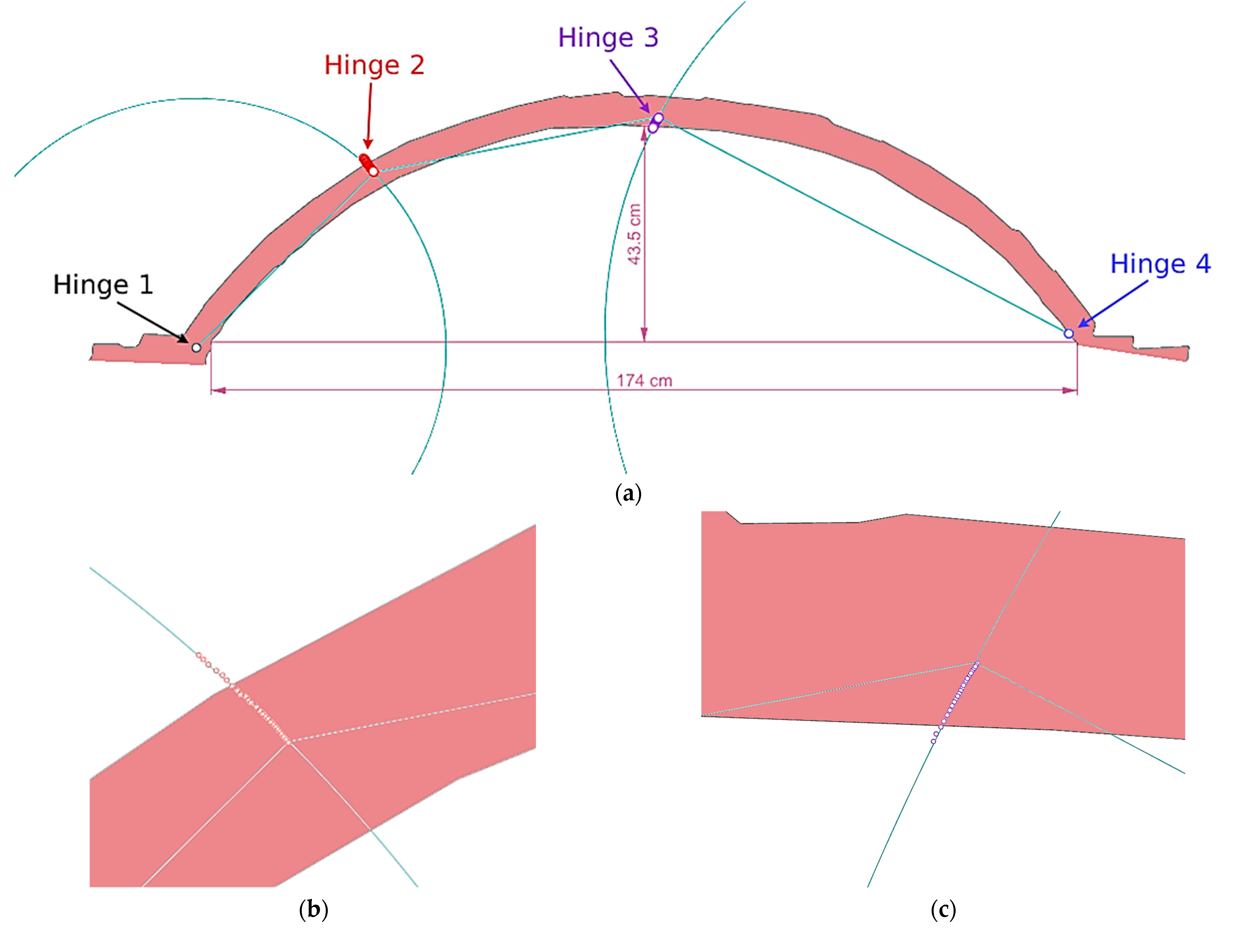
For each arch, the video image was superimposed on the corresponding 2D elevation model. The slight distortions observed in the video were adjusted performing the corresponding dimensional scaling. The coordinates of each position of the hinges located by tracking were exported, and the same correction was made to these coordinates. With all the information transferred to the Rhinoceros graphical interface, several issues could be verified. First, the compatibility of the movements of the resulting pieces in the collapse configuration. It was verified that a rigid solid movement occurs, since the two hinges closest to the supports have no displacement (hinges 1 and 4 in
Figure 9a) and each of the other two follows a trajectory very close to a circular arc. In
Figure 9b, hinge 2 moved upwards and in
Figure 9c hinge 3 moved downwards). It can also be seen that the section of the arc between the two displaced hinges determines the distance between these two hinges.
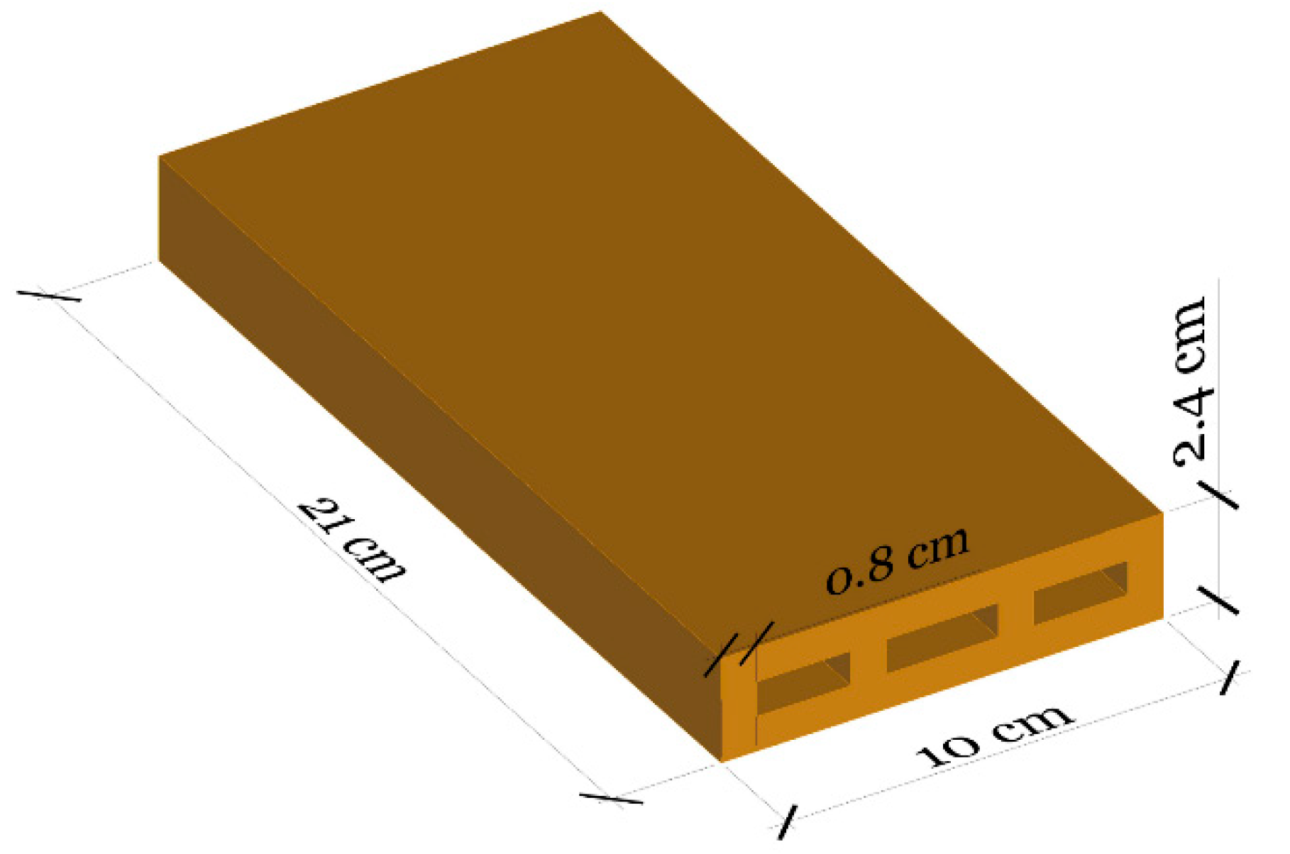
To estimate the effective plastic moment capacity of the vaulted arches, Equation (2) was applied, based on the principle of virtual work. It should be noted that, unlike in homogeneous materials, this value is not a fixed property but depends on the thrust line and loading conditions; in this context it is used as a didactic measure to compare collapse mechanisms. The external work was obtained by estimating the weight of each individual block into which the arch was divided after collapse, together with the applied loads. The average specific weight of the arches was taken as 11.3 kN/m3. This value derives from the nominal density of the thin bricks (approximately 12 kN/m3), adjusted to account for their perforations, which remain unfilled during construction, and supplemented by the contribution of the gypsum joints. Although the gypsum paste has a higher density (approximately 16 kN/m3), its relative volume is small compared to that of the bricks, so the global density is necessarily lower than that of the solid brick material alone. The adopted value of 11.3 kN/m3 therefore represents a realistic gross density for the constructed arches. The weight of each gypsum sack was 0.17 kN, while that of the thermo-clay blocks was 0.09 kN.
In the Rhinoceros graphical interface, a small arbitrary rotation of one sexagesimal degree was imposed at a hinge assumed to remain fixed in position (i.e., without translational displacement). The positions of all blocks were then updated according to the kinematic compatibility of the assumed collapse mechanism. Each block was segmented into smaller parts, and the points of application of the resultant forces, both from self-weight and from the applied load, were determined for every segment as well as the corresponding displacements of these points.
Figure 10a illustrates the segmentation of the pointed arch and the blocks that produced its collapse.
Figure 10b displays the vertical displacements measured at each point of application of the loads of the catenary arch including the additional loads. The internal work was computed by measuring the rotation of each hinge, associated with the arbitrary rotation of one sexagesimal degree, in the Rhinoceros interface and multiplying it by the corresponding plastic moment capacity.
Figure 10c shows the segmentation of the segmental arch; the areas measured for the estimation of self-weight loads and the rotations measured at each hinge.
Table 2 presents the values obtained from the collapse tests, which were used to determine the plastic moment capacity of each arch. The aim was not to compare the results across the different geometries, but rather to gain a broader understanding of their collapse mechanisms and the extent of their load-bearing capacity. From the estimated plastic moment capacities, two main conclusions can be drawn that are common to all three cases. First, the plastic moment capacity of the tested arches is remarkably low, particularly when compared with that of other structural materials such as steel or reinforced concrete. This observation reinforces one of Heyman’s fundamental assumptions for masonry analysis—namely, the negligible tensile strength of the material—which, although conservative from a safety perspective, appears to be a realistic representation of the actual behavior. Second, the gypsum paste prepared by the students was likely of non-professional quality. Nevertheless, the measured values can be regarded as a lower-bound estimate of the plastic moment capacity that might be expected in a traditional brick tile vault.
3.3. Construction of Vaulted Stairs
Building upon the experience gained from the construction and collapse testing of arches, predominantly two-dimensional structural systems, the next stage of the workshop involved the construction of vaulted staircases partially supported by a wall. This exercise draws on the same fundamental principle as the earliest Mesopotamian vaults, which were initiated directly from an existing wall. This activity allowed participants to apply the geometric and structural principles learned from the arches to a more complex, spatially three-dimensional configuration, thereby reinforcing the transfer of theoretical knowledge into practical design and construction skills. In addition, a static load test was conducted to verify the structure’s reasonable resistance. Load testing of the following structures should not be regarded as rigorous quantitative experiments but rather as empirical demonstrations of structural behavior, in the same spirit as the load tests historically conducted by Rafael Guastavino to validate his tile vaults [
26].
Students began by constructing a small T-shaped masonry section with large bricks, approximately one meter in height and 1.5 m long. On the longer side of this wall, a catenary curve was drawn to serve as the template for the intrados profile of the staircase, ensuring that the resulting vault complied with standard tread and riser dimensions.
The bricks in the first row were placed on edge against the wall and bonded with gypsum mortar. No centering was used; therefore, each tile had to be held firmly in position by the operator (in this case, the student) for approximately ten seconds until the setting of the gypsum provided sufficient adhesion. When the second row of tiles was placed, each unit was supported not only along its edge but also at its end face, thereby increasing both the reliability of the support and the overall productivity of the construction process.
As in the case of the arches, the vault is built with two layers of bricks. For the second layer, the tiles are first soaked in water and then bedded with a generous layer of gypsum applied to the board face, replicating the technique used in the arches. In addition to the lateral wall, the staircase vault is supported on the floor at one end and on the front wall at the other, thus securing three of its four edges.
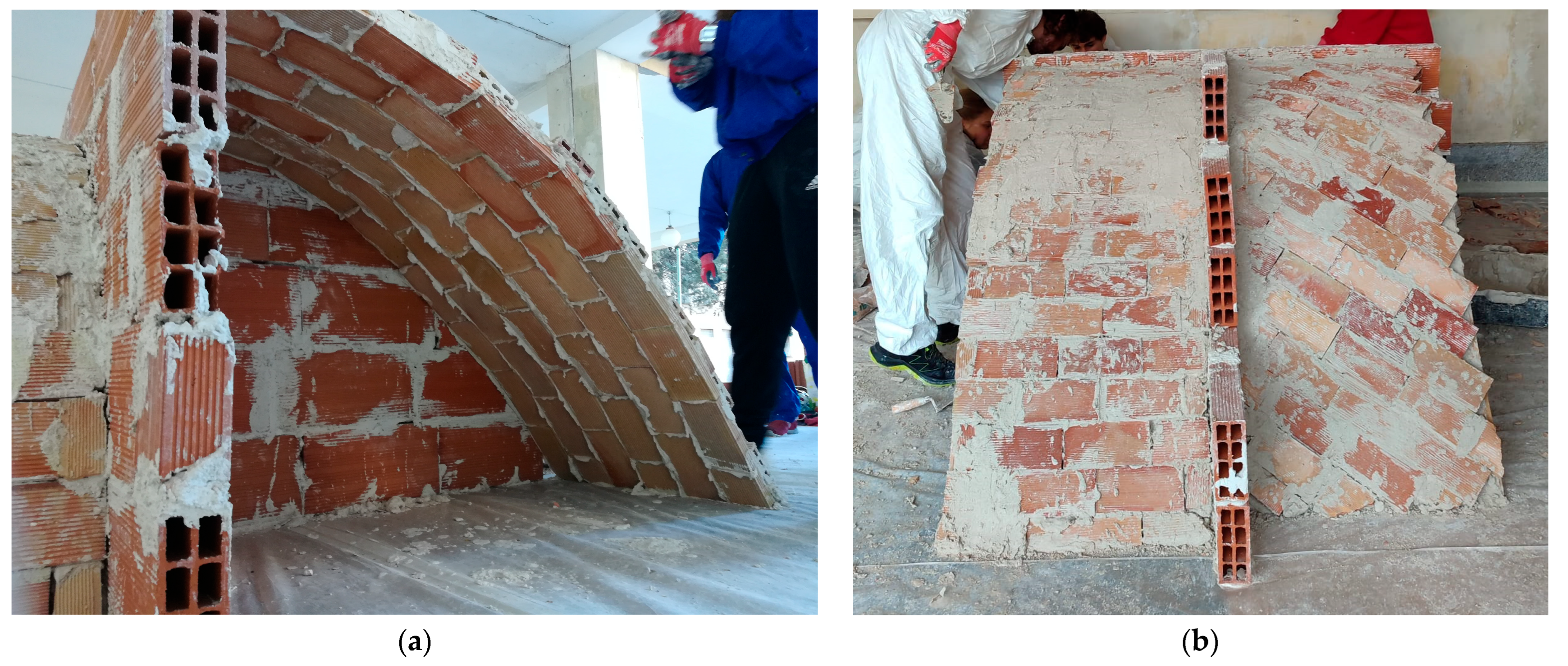
Figure 11a shows the intrados of one of the vaults for the stairs. This configuration significantly increases the overall structural strength of the assembly even if the gypsum has not been made by specialized masons.
In addition, the students experimented with different bonding patterns for the second layer of tiles. These patterns facilitated the arrangement of the bricks in a staggered configuration, thereby reducing the likelihood of creating continuous lines of weakness.
Figure 11b shows the two completed vaults with different brick arrangements on the second layer. After a curing period of at least 24 h following the completion of the vault construction, the structural capacity of the staircase vaults was assessed empirically, prior to building the steps. Several sacks were placed as an additional static load, with no signs of collapse observed. Given the satisfactory performance, a further test was carried out in which several people stood on the vault simultaneously, which implies a significantly greater load, confirming its ability to withstand the imposed load. After confirming that collapse could not occur under the imposed static loads, these vaults were demolished, having verified the structure’s reasonable resistance.
3.4. Construction of Ribbed Vault
Each day, the students in attendance were divided between the construction of the ribbed vault and the construction of the dome, although all students were able to participate in both structures.
The ribbed vault was designed and constructed following the principles of Gothic architecture. This type of vault is an intersection vault in which, unlike groin vaults, the diagonal ribs are built first, along with the perimeter arches.
The process begins with the layout of the plan on the ground, which in the case of a simple ribbed vault consists of a square with its two diagonals. The arches are then projected onto the ground to obtain their true dimensions. The simplest and most common form of the Gothic diagonal rib, contrary to the belief held by many architectural historians, is the semicircular arch. This rib determines the height of the vault.
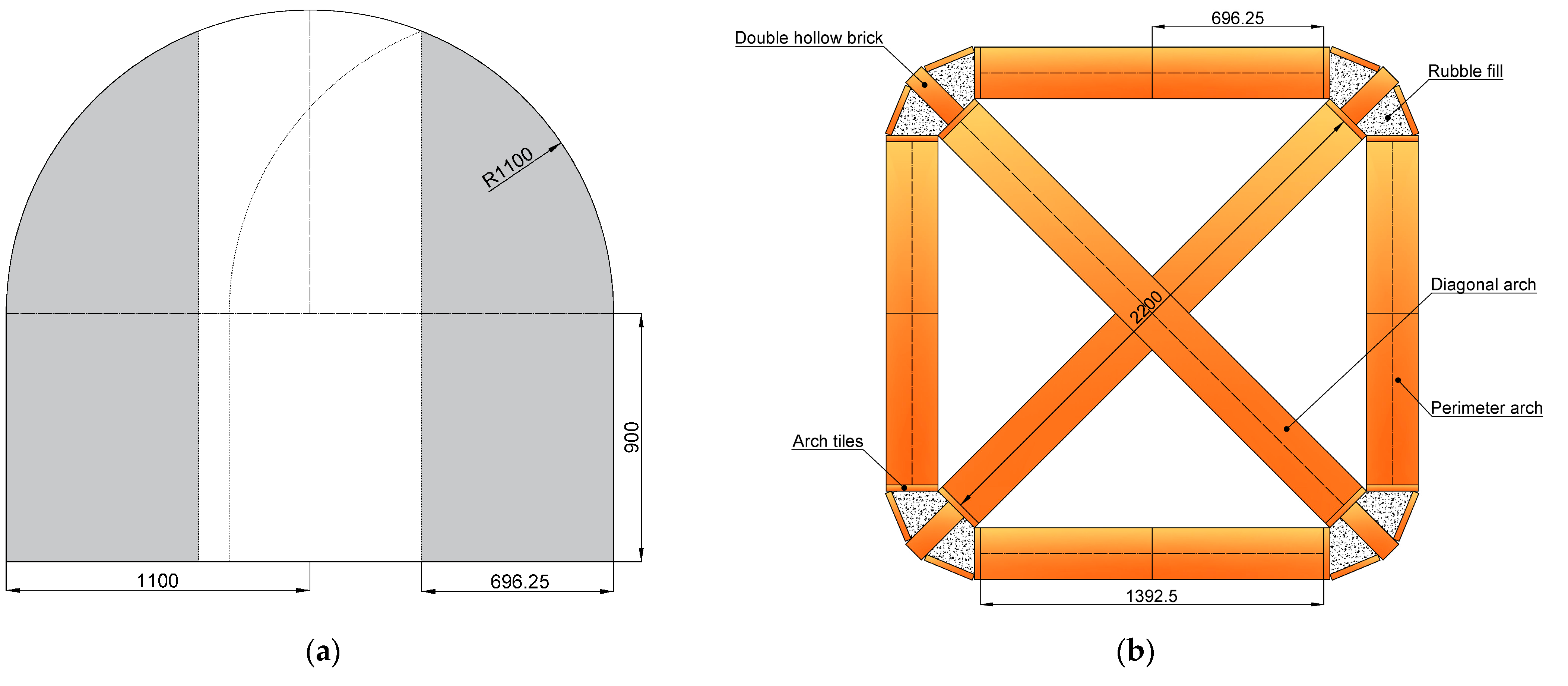
The vault was supported on four starter piers 0.9 m in height. For a diagonal span of about 2.2 m, the apex of the vault would be 2 m above the floor, allowing a tall student, or one standing on a small platform, to reach and place the bricks.
Figure 12 shows the centering designed for the diagonal arches.
The first step was to build one of the diagonal ribs in its entirety on a centering. Before removing the centering, the piers were extended upward on the extrados side of the rib to approximately half their final height. This ensured that the visible rib was, in reality, only the portion between the infill masses, which contributed to stability despite its slenderness (two layers of tiles, about 6–8 cm thick). Structurally, the ribs acted as the primary load-bearing elements of the vault, channeling forces towards the piers and allowing the infill panels to be constructed with minimal centering and reduced weight.
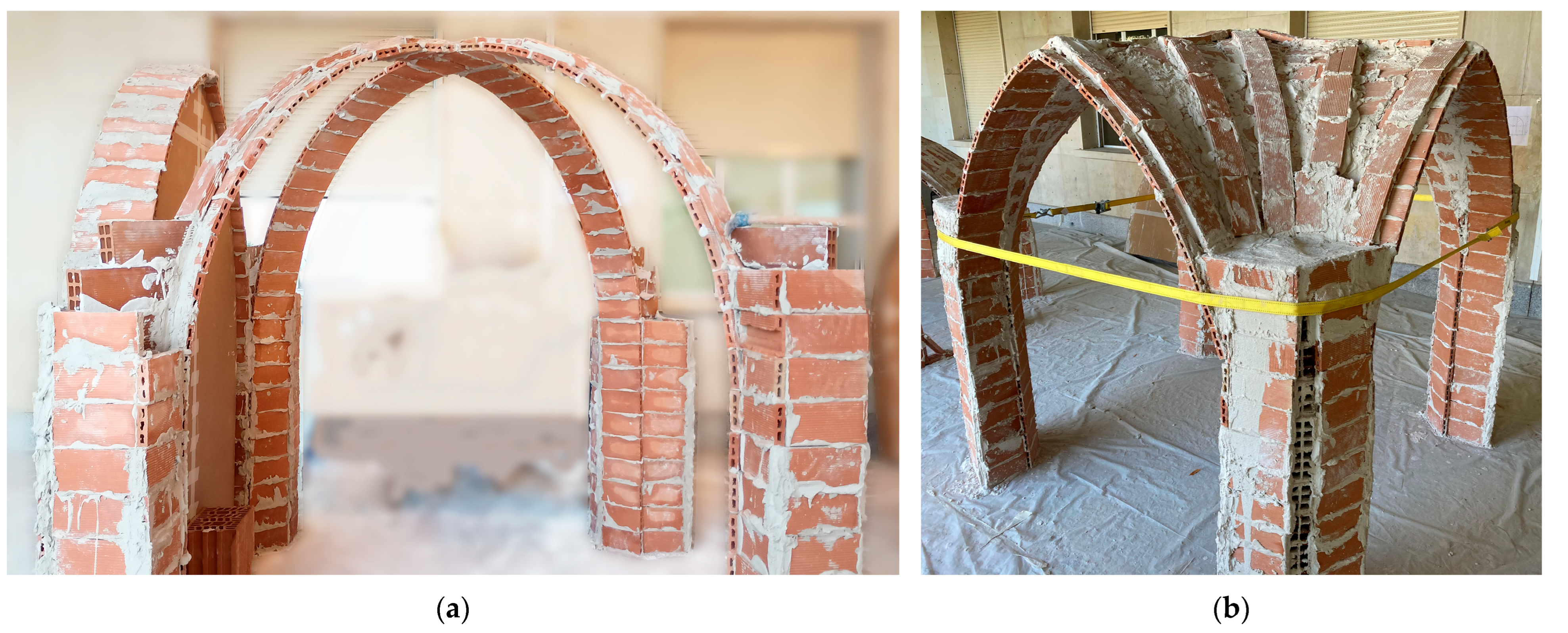
Next, the centering was lowered, rotated by 90°, and used to construct the second diagonal rib. In this case, the rib was interrupted at the keystone, requiring a more precise fabrication of the centering. Once completed, the appearance of the diagonal ribs could be observed as shown in
Figure 13a.
The perimeter arches could be constructed using several possible approaches. In most cases, the aim was to roughly match their height to that of the diagonal rib apex, which meant they had to be pointed arches. A common Gothic practice was to use the same radius of curvature for both the diagonal ribs and the perimeter arches. This allowed the centering used for the diagonal rib to be cut into two parts, which, when joined, formed the perimeter arch as illustrated by the shadow area in
Figure 12a.
Once the skeletal framework of the vault, comprising the two diagonal ribs and the four perimeter arches, was completed, the spaces between them could be closed without centering, forming the vault’s infill. This infill, or webbing, could be left as a single layer or doubled for greater strength. Tierceron and ridge ribs were constructed on the extrados of the vault, laid directly onto the surface with a generous layer of gypsum.
Figure 13b shows the ribbed vault after its completion with the piers’ extension and the tierceron and ridge ribs. Since no buttresses or adjoining vaults were included in the design, a safety restraining tie was installed to resist the horizontal thrusts of the vault.
From an educational standpoint, this exercise provided students with a direct understanding of the Gothic construction sequence and the structural logic of ribbed vaulting. By first constructing the ribs, they were able to experience how these elements define the geometry, enable lighter infill construction, and permit efficient reuse of centering, thus linking historical construction methods with practical considerations in masonry design.
3.5. Construction of Hemispherical Dome
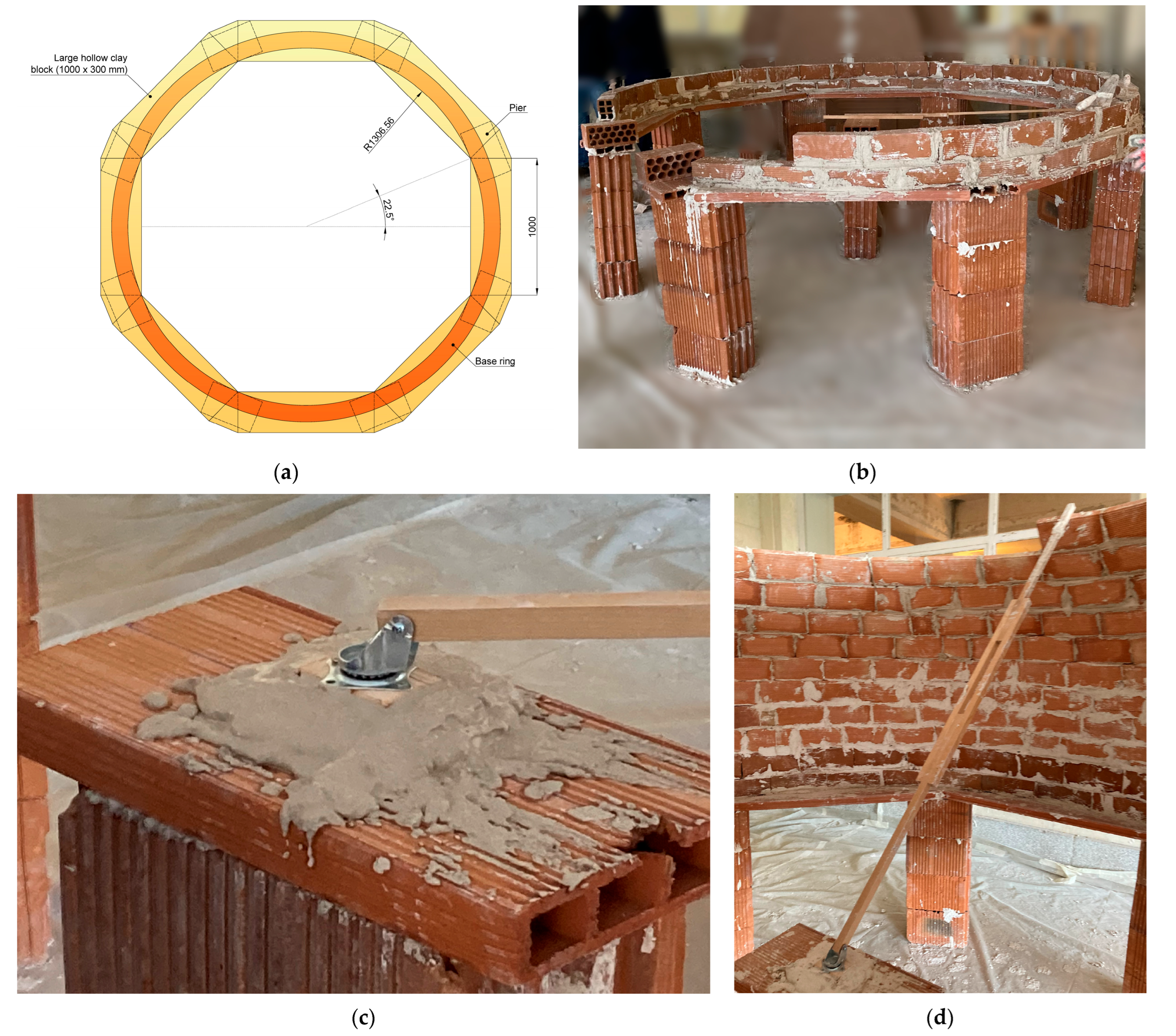
The hemispherical tile dome was designed to rest on eight piers built of hollow thermoclay blocks. Between these piers, seven hollow clay slabs (1.0 m long, 0.30 m wide, and 0.05 m thick) were placed as lintels, leaving the eighth side open to form an entrance framed by a semicircular arch. To set out the dome, an octagon of 1.0 m side length was first traced on the ground as shown in
Figure 14a. The piers were positioned at the corners of the octagon, extending outward. Two courses of double hollow bricks were laid to form the initial rings that work as encircling ties (
Figure 14b).
Once this base was completed, the center of the hemisphere was established by constructing a small pier, also built of hollow thermoclay blocks. On top of this pier, a spherical joint was installed, capable of rotating in all directions (
Figure 14c). Attached to the joint was a rod, a pivoting radius arm with a length equal to the radius of the dome. The pivoting radius arm, fitted with a hook at its free end, served as a guide to accurately place each successive ring of bricks that would ultimately form the dome.
The construction proceeded ring by ring. The first horizontal rings were relatively simple to execute and were laid in staggered bond. As the bricks gradually tilted, the process became more demanding: the gypsum paste required precise preparation, and laying the bricks without the use of centering demanded skill, especially at the beginning of each ring, where support was available only along one edge.
The diameter of the oculus was designed as one-fifth of the dome’s span, replicating the same proportion observed in the Pantheon of Rome. Given the intrados radius of 1.31 m, and in order to avoid longitudinally cutting the slabs, the final oculus diameter was set at 0.6 m. The rim of the oculus, being particularly fragile, was reinforced with a ring formed by arranging bricks radially in a comb-like pattern; alternatively, meridional ribs could have been adopted. According to shell theory [
27], thickening the lower third of the dome would be particularly advantageous to resist the tensile stresses that develop in the lower zones of rotational domes. In this case, following Heymann’s guidelines, the dome’s support on the lintel slabs was strengthened by a ring beam of thicker bricks, as seen in
Figure 15b.
Finally, additional half-bricks bonded with gypsum were placed on the extrados to facilitate access to the upper part during the subsequent load tests.
3.6. Collapse Tests of Vault and Dome
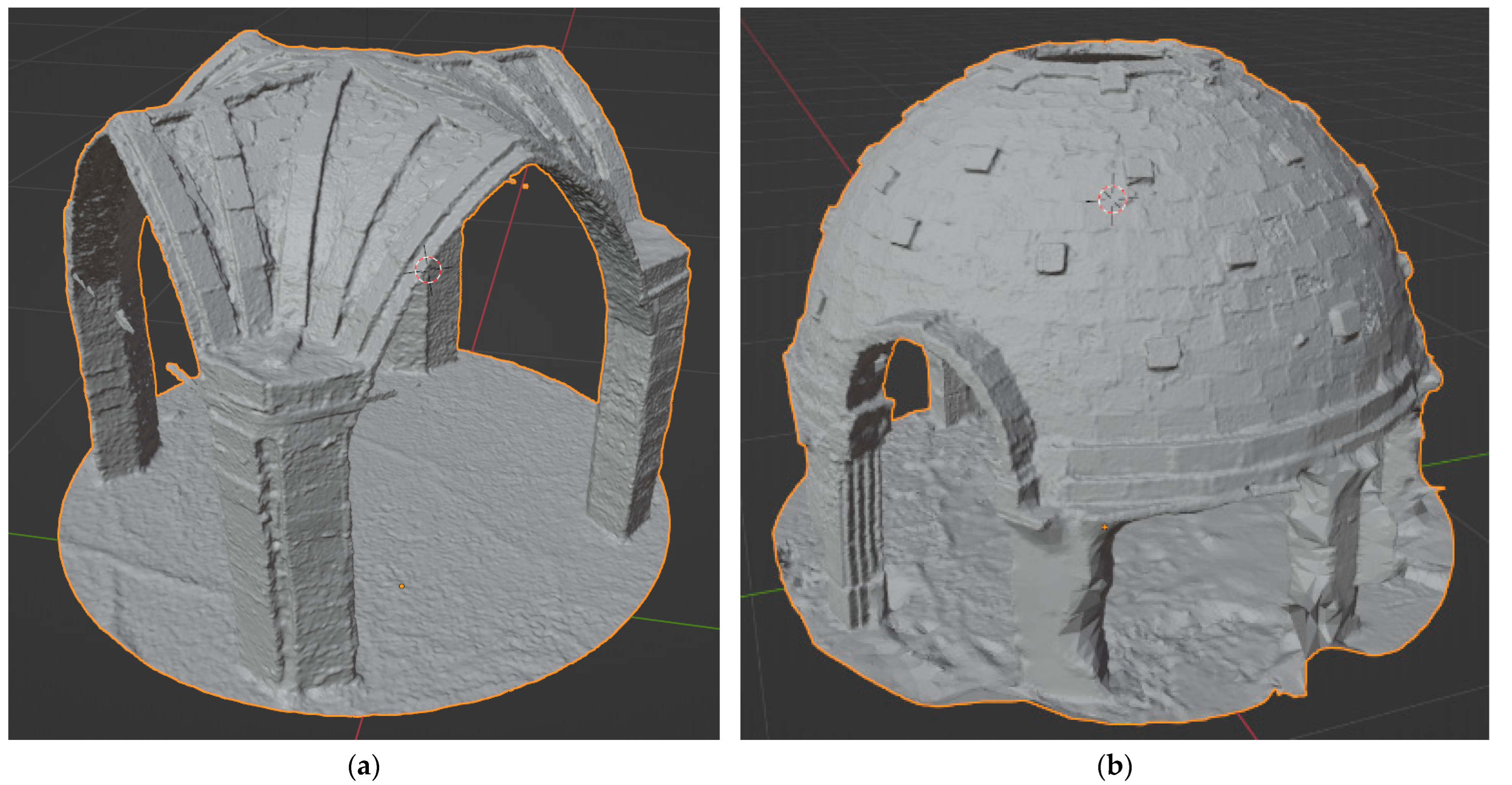
As with the arches, 3D digital models of both the ribbed vault and the hemispherical dome were produced once construction was completed, using the same photogrammetric reconstruction technique. A total of 226 photographs of the intrados and extrados of the ribbed vault were captured with the same camera described in
Section 3.2. The resulting 3D mesh, after filtering out all surrounding elements, contained 1.8 million vertices and 3.6 million triangular faces. To facilitate handling and visualization, a two-step decimation process was performed in Blender, reducing the model to 68,000 vertices and 126,000 triangular faces.
Figure 15a shows the ribbed vault model in Blender.
For the hemispherical dome, 224 photographs were taken of both the intrados and extrados. The final 3D mesh, again cleaned of surrounding elements, consisted of 3.1 million vertices and 6.3 million triangular faces. After a similar two-step decimation in Blender, the model was reduced to 70,000 vertices and 126,000 triangular faces.
Figure 15b presents the hemispherical dome model in Blender.
The accuracy of the models was verified by comparing selected dimensions with direct measurements taken after finishing the construction, ensuring that the digital reconstruction preserved the geometry of the built structures. This visualization not only confirms adequate image overlap and coverage but also illustrates the reliability of the camera pose estimation, which is crucial for the accuracy of the reconstructed geometry.
Beyond their documentation value, these simplified models proved highly effective for pedagogical purposes, as they allow students to visualize the geometry interactively, perform two-dimensional extractions, and even use them as a basis for structural simulations. In this way, the photogrammetric documentation not only complemented the workshop but also extended its didactic potential.
Once the 3D models were produced, the constructed vaults were subjected to load tests without removing the safety restraining tie. The ribbed vault was first loaded gradually with 20 gypsum sacks weighing 0,17 kN each, placed on the ridge ribs, without the appearance of cracks or even perceptible deformations. This represents an additional load of approximately 3.4 kN on top of the self-weight of the vault. The vault was then unloaded, and a second test was performed in which a total of 12 people (including both students and instructors) carefully stood on the vault, under close supervision to ensure safety. This corresponded to an estimated surcharge of approximately 8 kN, based on the average body weight of the participants. When 12 people stood on top of the vault, they occupied the entire available area, so their individual loads were distributed across the whole vault surface. Again, no cracks or deformations were observed.
After unloading, the vault was subjected to a test of imposed deformations to bring it to collapse after having removed the restraining tie. Using the restraining tie attached to a large concrete pier, a slow lateral displacement was applied to one of the piers of the ribbed vault in the direction of a perimetral arch. This process of loading, simulating an imposed deformation, and the subsequent collapse was filmed from several angles using video cameras. The 3D models were then employed to analyze the formation of the collapse mechanism.
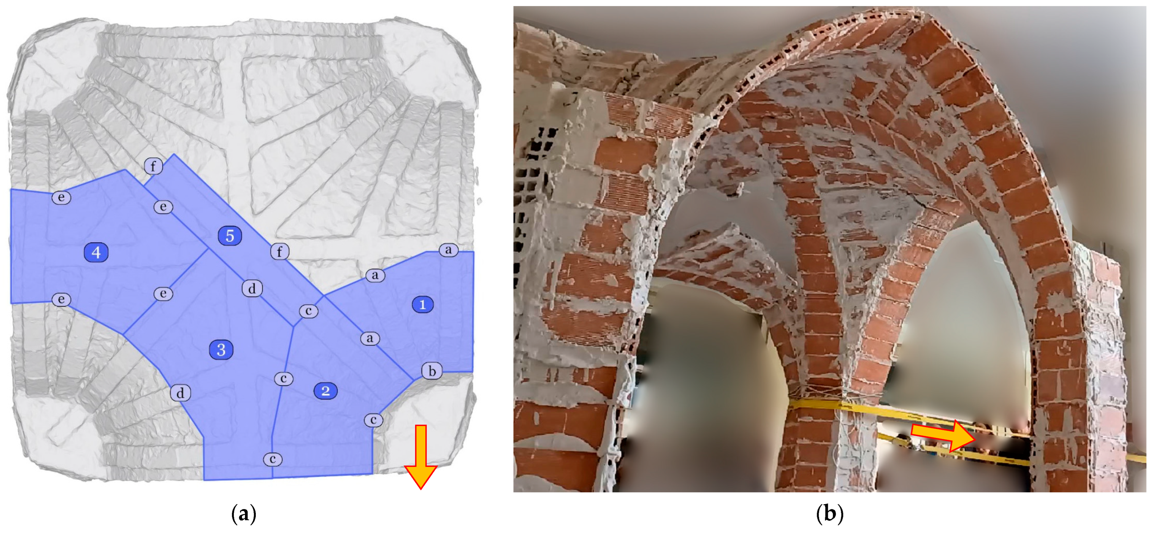
Figure 16a shows the yield lines and the panels formed during the collapse identified on the 3D model, together with the direction of the applied force at the junction between the top of the pier and the springing of the vault.
Figure 16b displays a video frame capturing the moment of collapse initiation.
It should be noted that the plastic analysis framework is explicitly applied only to the case of arches, where the geometry allows for a clearer and more didactic understanding of the underlying principles. In the case of vaults and domes, however, the behavior becomes geometrically more complex, and additional factors such as membrane action and three-dimensional interaction come into play. Therefore, the discussion of these structures is based primarily on experimental observations and descriptive analysis, rather than on a direct extension of plastic theory.
The analysis of the observed collapse mechanism reveals several aspects that hold didactic value for students, enhancing their understanding of structural behavior beyond theoretical models. First, the collapse is geometrically complex due to the shell-like behavior of the masonry structure. Second, it is difficult to identify the precise internal forces responsible for the opening of the cracks (whether bending, tension, torsion, or a combination thereof). In addition to geometry, the heterogeneity of the constituent materials and their mechanical properties contributes to this complexity. Third, the infill placed in the spandrels above the piers up to one-third of the arch height significantly increased the resistance of the vault, particularly at the pier where the imposed deformation was introduced. Finally, the ribs on the extrados influenced the pattern of yield lines: most of them either followed paths parallel to the ribs in areas where the shell consisted of a single layer or formed perpendicularly to them.
The hemispherical dome was subjected to load tests analogous to those carried out on the ribbed vault. First, twenty gypsum sacks were gradually placed around the edge of the oculus, corresponding to an additional load of approximately 3.4 kN. No visible cracks or deformations were observed under this load. The sacks were then removed, and a second test was performed in which a total of 12 people, including both professors and students, carefully climbed onto the dome, assisted by the half-bricks bonded with gypsum on the extrados to facilitate access. This represented an additional load of about 8 kN, based on the average body weight of the participants, which the dome successfully resisted without noticeable deformation or cracking. When 12 people stood on top of the dome, they occupied the entire available area, so their individual loads were distributed across the whole dome surface.
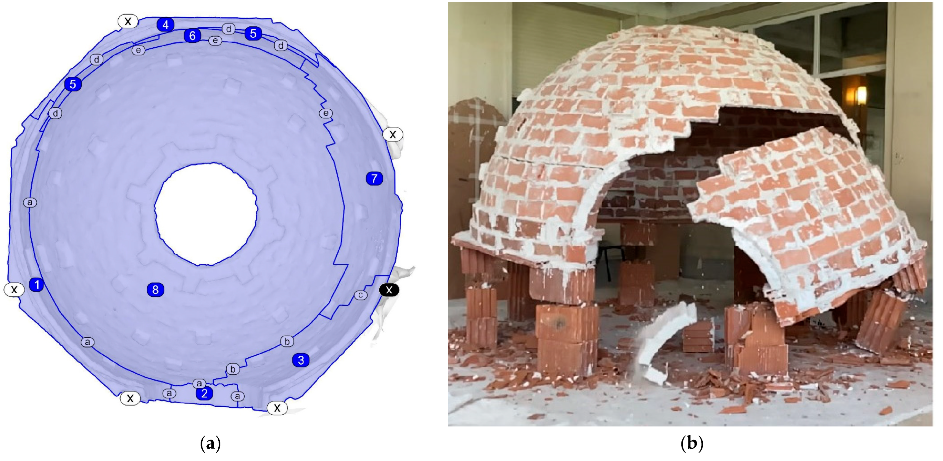
Following these load tests, the dome was subjected to a demolition process in order to study its collapse mechanism. The process was also filmed from several angles using video cameras. Under strict safety protocols and within a controlled perimeter, four alternate supporting piers were first removed, without any visible signs of cracking or deformation. Subsequently, a fifth pier was demolished, leaving nearly half of the dome cantilevered, yet still without evident damage. Collapse only occurred after one of the two remaining diametrically opposed piers was removed. In this case, the failure mechanism was driven by the combined effect of the loss of support and the impact of the dome’s base against the rubble of the demolished piers.
Figure 17a illustrates the yield lines and the failure panels identified in the 3D model of the collapsed dome. The white boxes with an “X” inside indicate the piers that were demolished in previous phases. The black box with an “X” inside indicates the demolished pier that caused the collapse.
Figure 17b presents a video frame of the actual collapse. The resulting crack patterns largely followed the brick joints, reflecting the absence of ribs on the extrados, in contrast to the collapse behavior observed in the ribbed vault.
The analysis of the load tests and the collapse of the dome offers significant educational insights for students. First, the dome demonstrated remarkable strength despite being constructed largely with a single layer of thin bricks. Second, the intermediate portion of the dome (namely, the rings adjacent to the brick ring beam) must have withstood significant tensile stresses during the load tests without exhibiting signs of failure. This highlights the crucial contribution of gypsum in providing tensile resistance and ensuring the stability of tile vault structures, even when the gypsum is prepared by non-professional workers. Much of this enhanced strength arises from the three-dimensional stress distribution developed within the dome shell. This behavior is consistent with historical evidence of the reliability of thin-tile vaults.

