Article

Systematic Design of Ancient Machines’ Models: Leonardo da Vinci’s Glider

by
Lorenzo Fiorineschi
1,*,
Federico Rotini
1 and
Roberta Barsanti
2
1
Department of Industrial Engineering, University of Florence, 50139 Firenze, Italy
2
Museo Leonardiano, 50059 Vinci, Italy
*
Author to whom correspondence should be addressed.
Heritage 2022, 5(3), 1593-1611; https://doi.org/10.3390/heritage5030083
Submission received: 24 May 2022 / Revised: 21 June 2022 / Accepted: 29 June 2022 / Published: 6 July 2022

Abstract

:
Virtual or physical models of ancient machines are often used for museum exhibitions, documentaries and/or cinematographic works. Especially for high-fidelity models, complex activities are required, which actually lead the different stakeholders involved in the process to “design” an artifact (the model). As with any design process, the design of models of ancient machines can also benefit from the support of structured methods that guide the designers from the early “ideas” to the final design. This paper proposes a systematic approach specifically tailored for the interpretation and design of ancient machines, where a methodological tool is provided to manage both idea-generation and information-gathering activities. The method was applied to the design of a model of the delta wing conceived by Leonardo da Vinci (i.e., the glider represented in the Codex Madrid 1, Folio 64r), allowing to analyze and obtain an embodiment of the machine with the required fidelity level, thought to be realized in real scale.

1. Introduction

Information about ancient machines are often fragmented and available drawings rarely allow unambiguous interpretations. Therefore, when trying to re-build such technologies, the involved stakeholders (e.g., historians, designers, manufacturers, museum staff, etc.) need to perform complex design activities on the basis of incomplete technical information about what the machine was actually intended to do, how it was intended to perform these functions and how it was intended to be manufactured.
Taking the example of Leonardo da Vinci, he proposed several concepts of different machines for a multitude of purposes [1,2]. Accordingly, many museums host physical models or provide means for observing virtual models of the Leonardo’s machines. In some cases, da Vinci provided a sufficient and quite detailed amount of information that allowed the reproduction of these machines quite easily (e.g., for the hydraulic saw of the Codex Atlanticus Folio 1078r). Generally speaking, Leonardo often provided quite comprehensive sets of illustrations about the conceived devices and/or the different alternatives of the parts intended to be used to build the whole system [2]. Nevertheless, the interpretation of Leonardo’s sketches is often not self-evident, and can undergo successive integrations or even corrections, as shown by Hollister-Short [3] for textile machines. In addition to that, several times the information provided in the available documents is insufficient to understand how the machine or part of it actually work or even what it was intended to do. This is the case of the example considered in this work, i.e., the so-called “Delta Wing” of Leonardo (from Codex Madrid 1, Folio 64r in the lower part of the sheet), also acknowledged as one of Leonardo’s studies about gliders. It is acknowledged as the most advanced of Leonardo’s concept of a glider [4], and in 2002 a replica was built by the University of Liverpool, in order to be tested in a wind tunnel [5]. However, as reported by the same staff, the considered model “was not a perfect representation of Leonardo’s idea” [5]. More particularly, the considered geometry was not strictly linked to the original sketch or Leonardo da Vinci, and the exploited materials and building technologies were not fully available in the fifteenth century. A comprehensive analysis of Leonardo’s studies about flight and aerodynamics falls out of the scope of this work. Detailed literature contributions can be found about the argument (e.g., [6,7,8]). Nevertheless, to the knowledge of the authors, no published work exists that analyses and discusses the glider in detail, and (more important for the aim of this work) how high-fidelity reproductions can be created.
The authors of this work previously worked to design and build a small-scale physical model of the glider, for the Museo Leonardiano of Vinci (Italy). The systematic design methodology [9,10], which comes from the industrial engineering field, was used as a reference to guide the design process, from the clarification of the task to the realization of the technical drawings needed to manufacture the model. This was not an accident; indeed, besides being acknowledged to be the precursor of many branches of engineering (e.g., fluid dynamics [11]), Leonardo is also supposed to be the precursor of systematic approaches to supporting creativity in design processes [12,13]. Therefore, it was a pleasure to have the opportunity to apply modern systematic design approaches to the Leonardo’s work. However, from these precedent experiences it emerged that, notwithstanding the advantages given by a systematic procedure, the process could be tailored and improved to provide more comprehensive support in the technological heritage context. In particular, the early phases of the process, where the “design task” needs to be formulated (i.e., which kind of model should be designed, at which fidelity level, etc.), are strongly influenced by the actual amount of information available from historical documents. This first activity is crucial to start the “conceptual design” of the reproduction process. However, the additional information that is extracted during the conceptual design of the model is fundamental to validate or re-discuss the hypothesized task. For example, during the concept design it is possible to discover that a “high fidelity” model cannot be built (or cannot work) without formulating an important hypothesis about how a specific part of the system actually works or can be built. It is possible that these hypotheses do not fit with the historian’s understanding of the technologies of the specific era, and then the original task needs to be re-discussed (e.g., a previous task related to a working model could be “downgraded” to a static mock-up, in order to not contradict current knowledge about the technological level of a specific era). Without a comprehensive understanding of the process, these multidisciplinary activities, where both technical and non-technical stakeholders are involved, can easily become a fuzzy sequence of chaotic and costly iterations.
To better support the process and to allow the structured management of the related activities, this paper aims at proposing a systematic-design approach specifically tailored for ancient machines’ models. The process is subdivided into well-defined phases and particular attention is paid to the conceptual design phase, where a tool recently proposed is implemented to support both design-space exploration and information-gathering activities (crucial when the original information is missing or too fragmented). Both structured and unstructured iterations about the phases are mapped and described to allow an in-depth understanding of the whole process.
The approach was applied to the case study of the Leonardo’s delta wing, and a new upgraded embodiment model is proposed through a computer-aided-design representation (CAD).
More precisely, the paper is structured as it follows.
In Section 2, the original information about the delta wing is reported, together with a short description of the physical model built in 2010 for the Museo Leonardiano of Vinci (Italy). In the same section, the fundamentals of the considered conceptual-design tool are reported, followed by a comprehensive description of the proposed methodological approach. In Section 3, the results from the case-study application are described and they are subsequently discussed in Section 4. In the latter section, the limitations of the work are also clearly explained, a set of further research hints are introduced, and the expected impact of this work is discussed. In particular, the main limit of the work concern the current impossibility of comparing the proposed approach with non-structured approaches, in order to quantify actual advantages. Indeed, the redesign of ancient machines is characterized by parameters that sensibly differ from those usually considered in normal engineering design activities, and still need to be comprehensively identified.

2. Materials and Methods

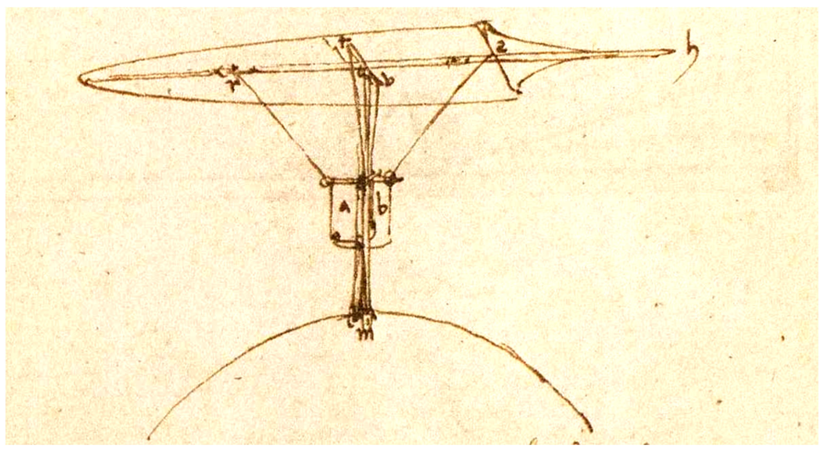
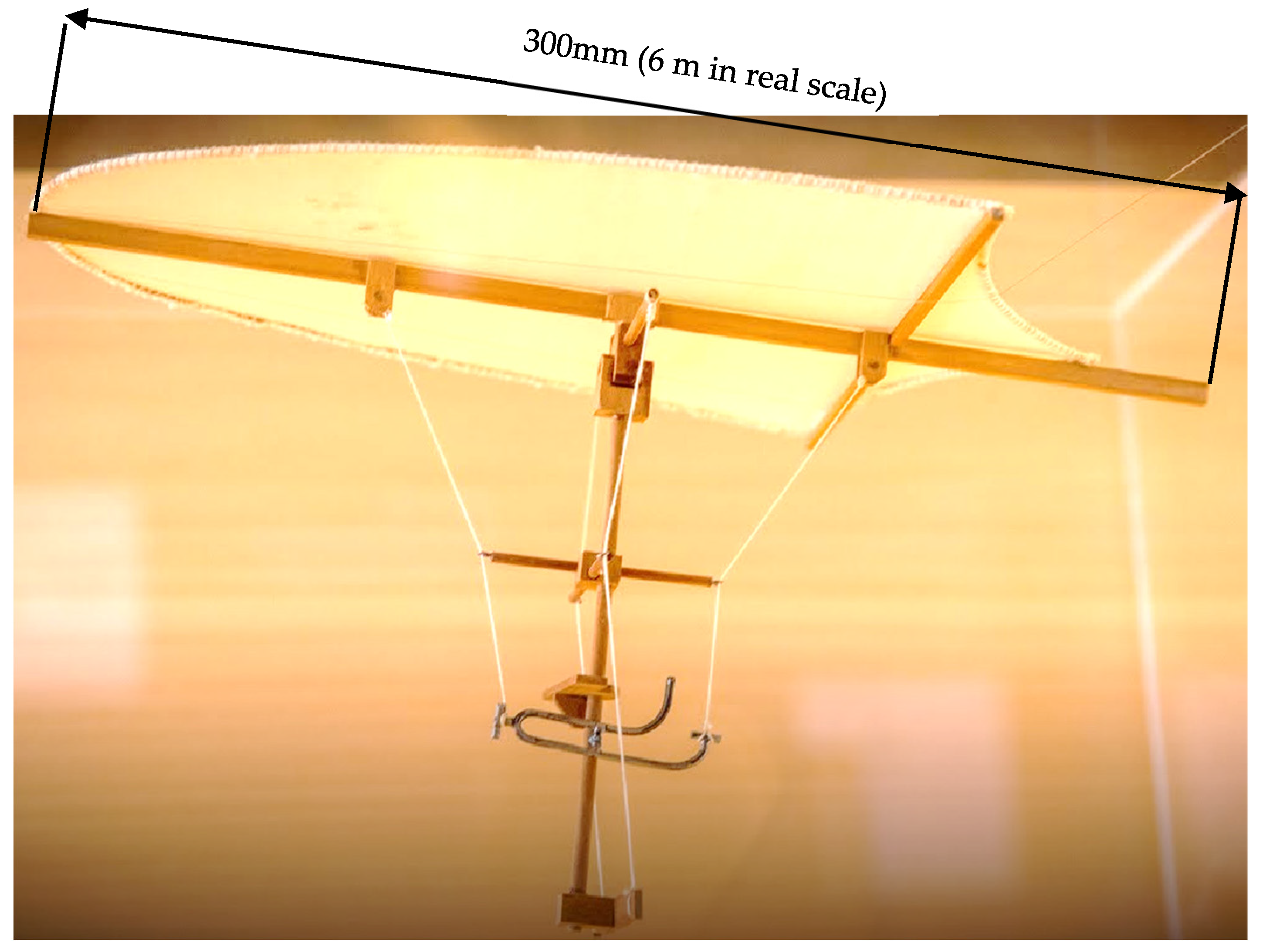
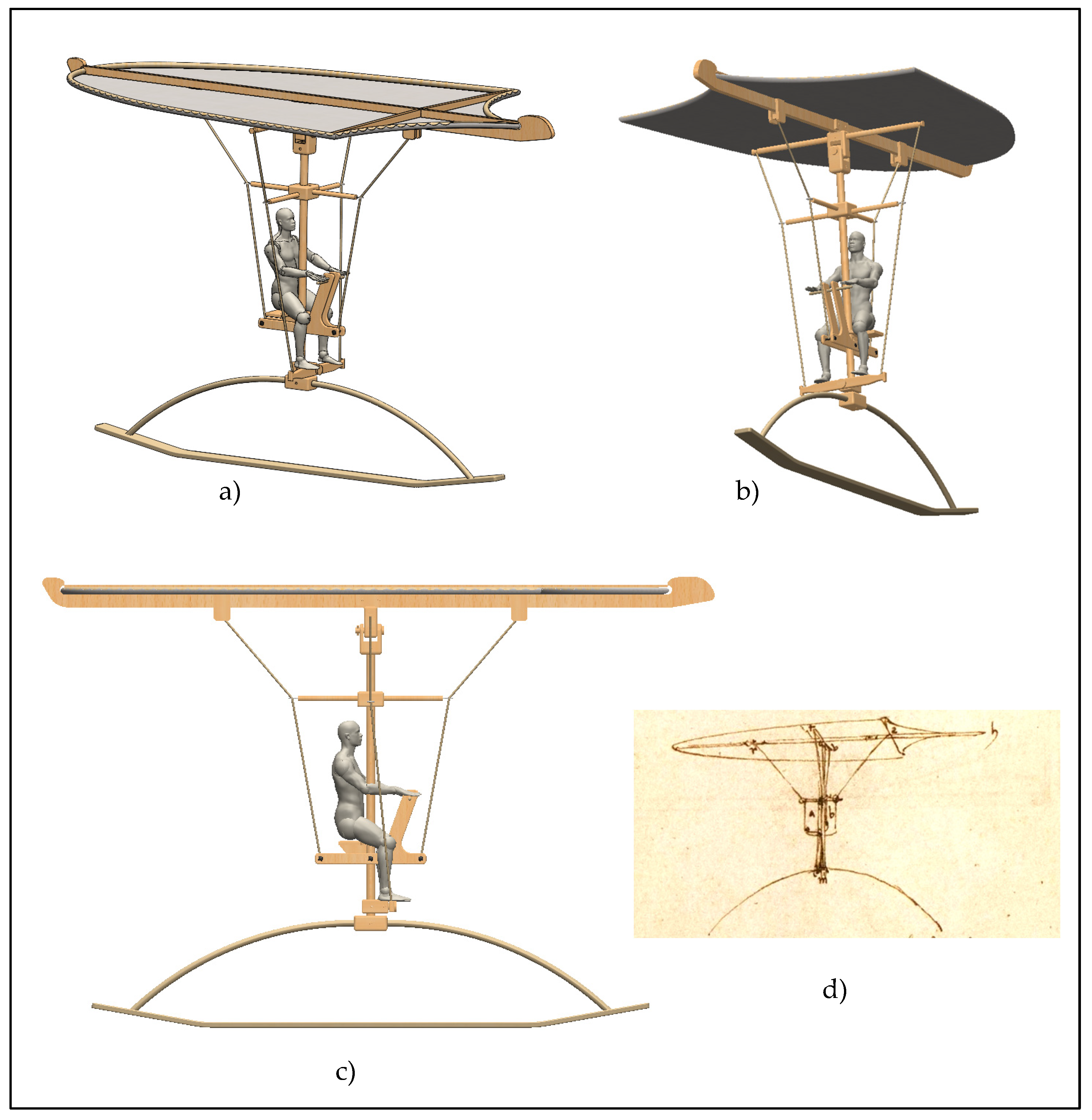
2.1. The “Delta wing” of Leonardo

What is named here as “delta wing” of Leonardo da Vinci can be found in the Codex Madrid 1, Folio 64r, and appears as shown in Figure 1. It looks like a bird’s feather, with something that resembles a pilot host and some control systems attached below it.
In particular, about this device, Leonardo originally wrote [14]:
“Questo è della medesima natura che quello di sopra. E ll’omo tieni i piedi in m e ‘l bussto in a b. E sse ‘l vento, che viene per la linia h qualche volta entrando sotto, a uso di femina colla sua vite, potrebe qualche volta alzare h più che ‘l dovere, allora l’omo tiri la corda S in basso. E così facci co’ l’altre corde dove bisognia, e quando vol calare, tiri la corda S e dirizzerassi atterra.”
In an effort to translate these words, which are written in archaic Italian language, it is possible to interpret what Leonardo said as it follows:
This device is of the same nature of the one above (the flying sphere in the Folio 64r of the Codex Madrid 1). The man keeps his feet in the device indicated with the letter m, and the chest in the zone indicated by letters a and b. If the wind, coming from the direction parallel to the element indicated with the letter h, sometimes coming from below, similarly to what happen with the screw and the nut, may rise to much the element h. In this case, the man can pull down the rope indicated with the letter S. Similarly, it can be done the same with the other ropes wherever needed, and when the man wants to land, it just need to pull down the rope S to direct towards the ground.
Unfortunately, no additional information was provided by Leonardo, leaving a non-negligible number of doubts about the details of the control system that he originally conceived (see Figure 2 for some examples).
In 2010, the Museo Leonardiano of Vinci, in collaboration with the University of Florence, performed an interpretation activity on the delta wing to build a small-scale physical model of the system for an exhibit of the museum. The design of the system, and then the interpretation of Leonardo’s sketch, was performed by following a systematic procedure [15], and allowed the formulation of important hypothesis about the expected real dimensions (by a direct comparison with current hang gliders), and to discuss construction details. According to the museum requests, the expected scale of the model to be produced was of 1:20, and, despite the small dimensions, many interesting details were implemented (see Figure 3). In particular, the ambiguous curved line (see Figure 2) was considered as not part of the system.

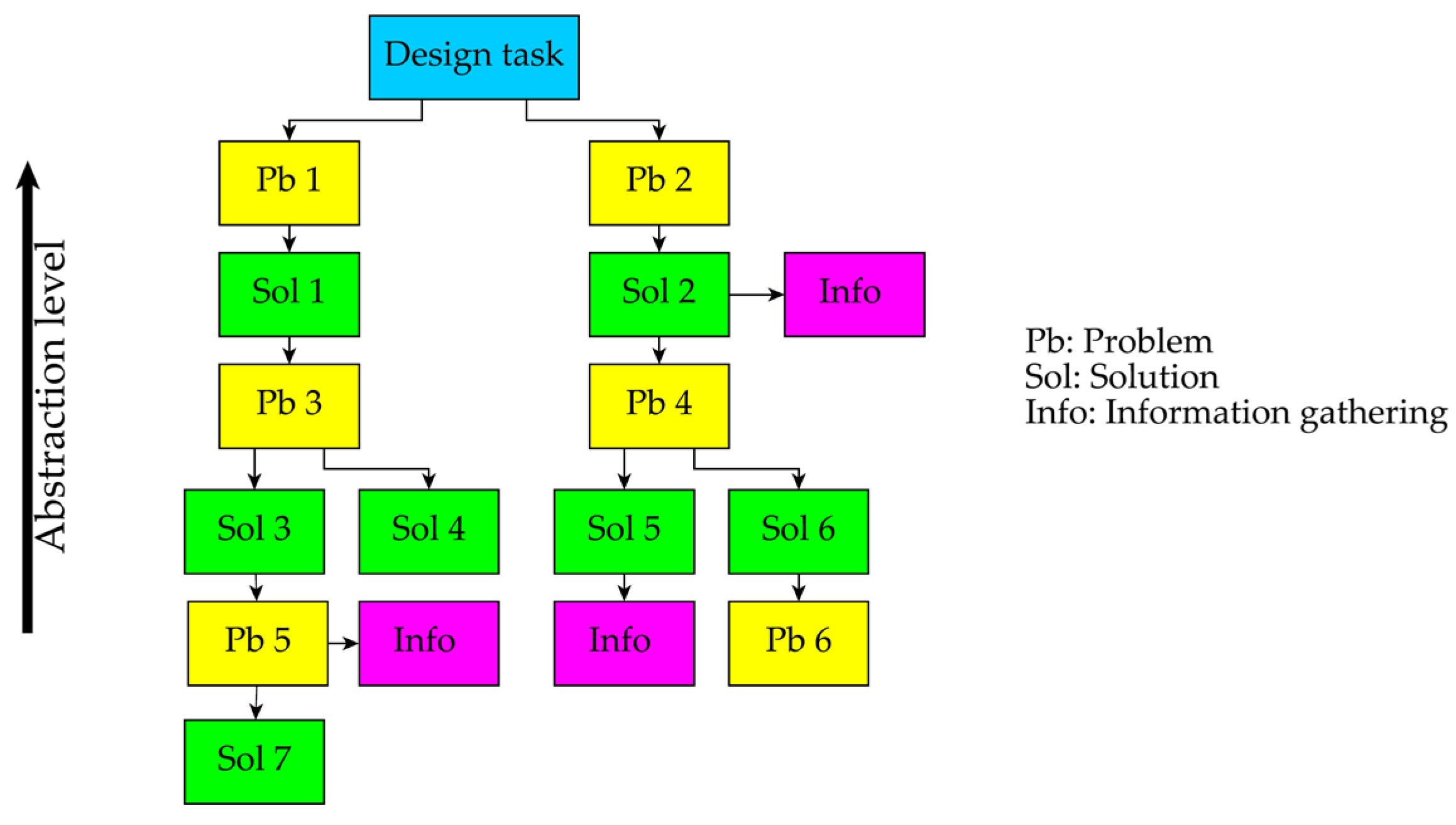
2.2. The Problem-Solution-Network

The problem–solution–network approach (PSN) is a systematic conceptual design method characterized by the schematization of ideas in terms of problems and related solution variants [16]. This specific approach allows the visualization of the main problems that a system is expected to solve, and the variety of solutions that can be considered to solve each of them. Considering that each solution is characterized by one or more sub-problems to be solved, by following a set of six fundamental rules it is possible to obtain a structured hierarchical network of problems and solutions (see Figure 4), that allows the exploration and management of the design space.
The PSN approach was initially conceived to overcome some flaws characterizing the well-known German systematic design method, and, in particular, the functional decomposition and morphology approach (FDM) [10,16]. The main advantages claimed for PSN (in relation to FDM), can be summarized as it follows:
  • Allows to visualize the explored design space in a single graphical representation.
  • Provides support for reducing the negative effects of design fixation (i.e., the counterproductive effects of unconscious fixation that the designer can have on specific designs or solution alternatives [17,18,19]).
  • Allows to solve each main design problem independently, thus enhancing multidisciplinary teamwork.
  • Allows to keep track of information-gathering activities for both problems and solutions.
A further development of the PSN was proposed in order to better manage abstraction levels of both problems and solutions [20], which was considered in this paper. In particular, the function–behaviour–structure (FBS) framework [21,22] was used (in a simplified form) to tag both problems and solutions. Table 1 shows the particular PSN boxes with the FBS-level distinction. To ensure a gradual passage from abstractness to concreteness during the design process, a quite-simple rule suggests the formulation of a subsequent box (i.e., a problem box if coming from a solution box, and vice versa) at the highest possible abstraction level [20]. In addition, as shown in Table 1, PSN problems cannot be formulated at the “structure” level, because they are not related to the system itself but to choices and/or decisions of the designer (e.g. “how to manufacture a specific part?” or “which dimensions are needed for this specific part?”). Indeed, possible questions about processes and technologies to be conveniently used for manufacturing specific parts (i.e., the PSN solutions at the structure level) can be expressed in forms of “information-gathering activities”, opportunely represented by the pink boxes in Figure 4.
The PSN approach originally developed for design purposes is constituted by three main phases:
  • The concept generation (CG), where the design space is explored in terms of problems and solutions sequences, leading to network hierarchically organized according to related abstraction levels.
  • The concept composition (CC), where a variety of possible combinations are proposed between the solutions from different PSN branches. In this phase, sketches are created by the designer to generate and visualize different overall concept variants.
  • The concept-selection (CS) phase, where the previously generated overall concept variants are selected through classical concept-selection approaches and tools (e.g., concept-selection matrices [23], selection charts [10] (Pahl et al., 2007) or QFD-like matrices [24]).
For the scope of this specific work, the most important part of the procedure is the CG, where the network can be created from the information available in the considered historical documents.
In particular, the “decomposition” of existing solutions is already used in the PSN approach to abstractly represent acknowledged technologies for specific product types (the reader can find extensive examples of this in [25], even if not strictly related to the redesign of ancient machines). This kind of activity has been mentioned here because it fits well with the interpretation of ancient machines. Indeed, as for standard design activities, where the designer needs to understand a specific solution before being able to reuse it, in this case it is necessary to understand how the ancient solution works before being able to reproduce it.

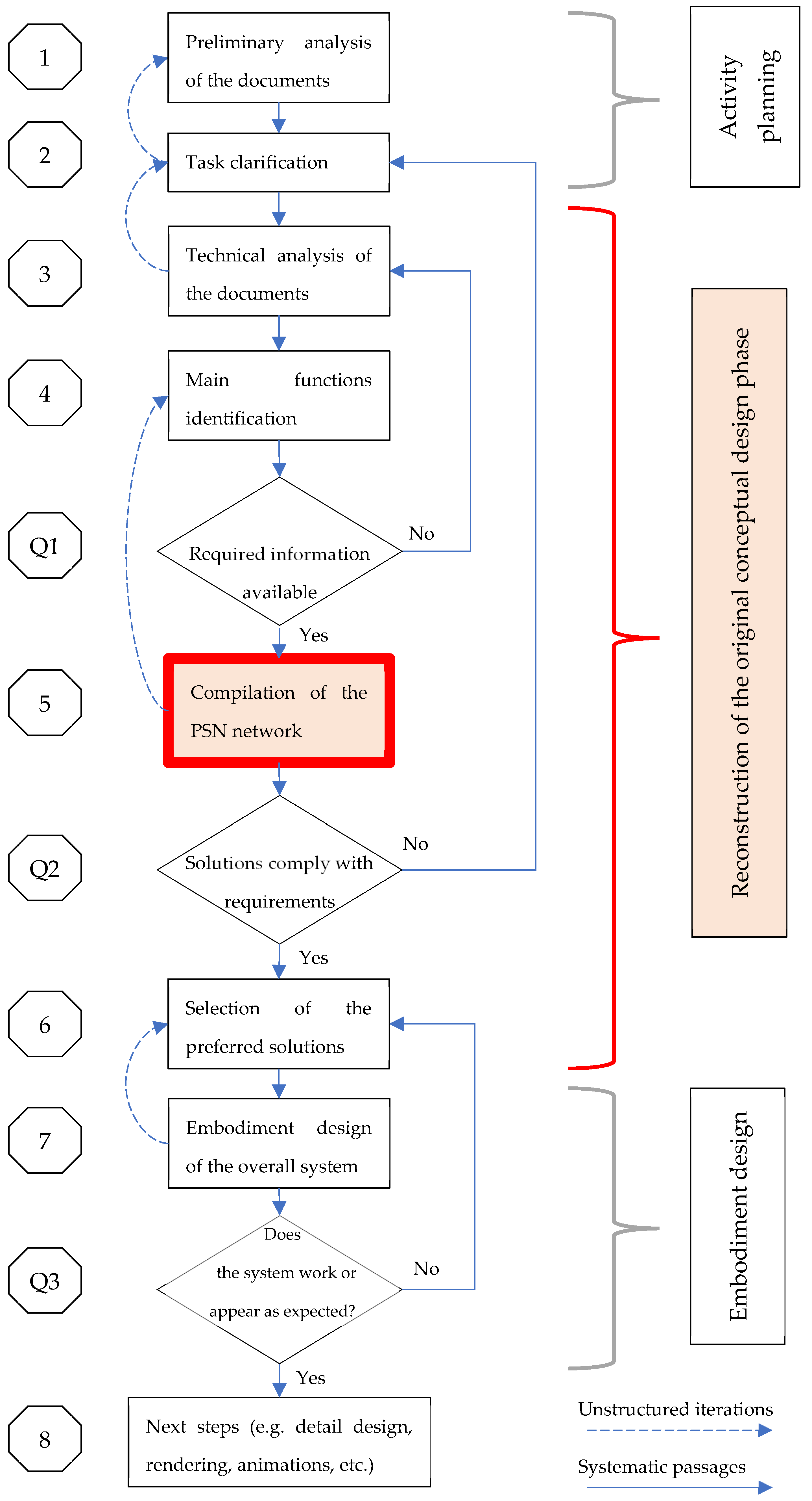
2.3. The Proposed Approach

The proposed approach is b ased on the well-known steps of the German systematic design methodology, which has been opportunely customized to the scope of the activity as shown in Figure 5.

2.3.1. Description of the Steps

The proposed procedural approach is based on the systematic subdivision of the design process into three main phases, i.e., the conceptual design (where the fundamentals of the system are generated), the embodiment design (where the geometry of the system is identified), and the detailed design (where each detail is defined and production documents are prepared). Of course, the interpretation of ancient machines is not the same task as a design process. However, very often the interpretation is performed in order to somehow reproduce the system (e.g., for further studies or for museum exhibition). In other words, the design subject is the “expected reproduction” of the ancient device.
Accordingly, the first part of the proposed approach aims at clarifying the “reproduction design task”. Indeed, there are several possibilities: e.g., simple images for further studies, physical mock-ups or virtual animations for museum exhibitions, as well as for cinematographic or video-documentary purposes. In particular, Step 1 aims at analyzing the available information from documents, in order to evaluate the feasibility of the reproduction and to extract preliminary data. Then, in Step 2, brainstorming sessions are expected to be performed between historians and technicians (e.g., engineers) to identify what can be reasonably carried out according to the available time and budget. Most importantly, especially when the available information is very limited, in Step 2 the team should decide the “fidelity level” expected for the reproduction in relation to the original drafts. For example, it is possible to try to reproduce the system by using the technologies of the specific era, or to build a modern prototype (with modern technologies and materials) somehow inspired by the ancient concept.
Concerning the next steps, of course the “conceptual design” of the system was originally performed by the ancient inventor (e.g., Leonardo da Vinci for the device considered in this work). Therefore, the main part of the proposed approach aims at reconstructing the concept that underpins the system to be reproduced (Step 3 to 6, and Questions Q1 and Q2 in Figure 5). In particular, Step 3 (technical analysis of the documents) aims at extracting the available technical information about the system (e.g., the expected purposes for which the device has been designed, how it works, the exploited energy type, etc.). In Step 4 (main functions identification), it is expected to identify the set of main functions that the system is expected to perform. More precisely, and according to the PSN approach, it is necessary to identify those functions that a “black box” representing the system at the highest abstraction level is expected to perform. To give an example, common clothes-washing machine can be represented at the highest abstraction level as something that removes filth from clothes, without any information about “how” to do that. Once the main functions have been identified, question Q1 is used to verify if the available information is sufficient to proceed further. For example, especially when a graphical representation of the ancient device is unavailable or heavily degraded, the team could be unable to identify a sufficient set of functions to be subsequently processed. In that case, it is necessary to further analyze available documents or to search for additional ones.
If the set of identified functions is deemed sufficient, Step 5 uses the PSN to analyze each function independently, to extract information about the possible behaviors and structures that the system “seems” to exploit. Indeed, due to the limited information, obtaining different interpretation variants is quite common. The PSN is then used to store and discuss each interpretation for each single function. Here, question Q2 arises, which is formulated to verify if and to what extent the solutions identified for each main problem are compatible with the requirements formulated in Step 2. Generally speaking, solutions stored in the PSN should accomplish the requirements expressed by both engineers and historians. For example, if the expected task is to design and build a high-fidelity and working physical model of the system, it is not sufficient to find a plausible working concept of the system, but details about materials, available resources, compatibility with the historical era, etc., need to be carefully verified by historians. If one or more sets of suitable interpretations are available in the PSN, it is then possible to proceed with Step 6, where the preferred one can be selected (i.e., specific problem–solution paths for each main function).
Once the preferred interpretation has been selected for each function, by referring to the available graphical representation (if any) or the original textual description (if any), the designer can proceed with the embodiment design of the system, preferably by using advanced 3D CAD (computer aided design) systems. Through 3D CAD it is also possible, if needed, to check the working principle of the system and, therefore, to consider further issues related to the functioning. This is also useful for those models employed in static exhibitions as the coherence of the main elements of the system with its function could be a fundamental requirement of the model.
If the obtained model fits with the expectations (see question Q3), it is possible to proceed with the subsequent operations (Step 7). More specifically, when it is expected that a physical model of the system will be manufactured, it is necessary to proceed with the detailed design phase to obtain the drawings and other technical documents useful for the subsequent phases of the development cycle of the physical model (such as, for instance, production, integration into the environment of the exhibition, etc.). Differently, when a physical model is not necessary, it is possible to work directly on the 3D CAD model, for example, to obtain renderings.

2.3.2. Systematic Iterations and Unstructured Passages

As shown in Figure 5, questions Q1, Q2 and Q3 lead to structured iterations, respectively, of Steps 3, 2 and 6. The possibility of facing these loops has been explicitly taken into consideration by the proposed approach, since they are triggered by verification of the availability of crucial information.
However, there are many reasons that can lead to the need of moving backwards in the process, which cannot be resumed or identified with a simple question box. This is why, in Figure 5, some “unstructured” passages are also mapped, i.e., from Step 2 to Step 1, or from Step 3 to Step 2, from Step 5 to Step 4, and from Step 7 to Step 6.
In particular, the backward step from Step 2 to Step 1 is intended to map all those iterations that might be necessary to comprehensively clarify the task. For example, in a multidisciplinary team, museum staff may desire to physically reproduce an ancient technical system, considering drivers such as the historical importance or the possible museum advantages in terms of new potential guests, the need to make the model easy to disassemble as it could be used in other museums or in traveling exhibits, etc. This kind of activity, although highly desirable, may have some kind of conflicts with the available budget or the available time, which might be insufficient for a high-fidelity reproduction. Iterations like this are somewhat undesired but necessary. Indeed, a preliminary task is expected to be proposed by a part of the team, then discussed with the rest of the team and the involved stakeholders. It is highly improbable that the first proposal will be accepted in terms of all aspects, and therefore it could be necessary to perform some iterations between Steps 2 and 1 to find the preferred task to be faced.
Iterations between Steps 3 and 2 are like the previous one, but more focused on the technical feasibility of the task. In this case, even if engineers are expected to collaborate in Steps 1 and 2, a comprehensive technical analysis of the documents should be carried out only when a preliminary version of the task has been defined. For example, the technical analysis required for a simple 2D sketch of the system (e.g., for book illustrations) is quite different from the technical analysis performed to search for the details needed to build a high-fidelity physical reproduction of the system. Once the preliminary task has been proposed, engineers are required to comprehensively evaluate the feasibility of the work on the basis of the available information, budget, and time. Iterations from Step 3 to Step 2 are then intended to refine the task and/or to re-distribute the available project budget.
After Step 4, question Q2 ensures that the information required to develop each functional part of the system is available. However, when building the PSN network, it may appear that the considered main functions are not capable of comprehensively representing the whole system, or (on the contrary) that one of the considered main functions is a sub-function of another main function. This is quite normal when a functional decomposition of an unknown system is performed, and it is even more probable in this case, where the available information is expected to often be not sufficient for a clear and unambiguous understanding of the system. Therefore, it is possible to face the need to adjust the set of main functions defined in Step 4.
Step 6, if comprehensively performed, ensures that the preferred “concept interpretation” is selected and then subsequently processed in Step 7. However, as for any design process, some additional problems may need to be faced when additional details are considered. Indeed, the embodiment-design phase is expected to develop the “concept” (usually roughly represented by means of hand sketches and textual notes) in terms of geometry, materials, kinematics (when needed) structural strength, manufacturing, and assembly operations (when needed). Therefore, if new problems cannot be easily solved in the embodiment-design phase (i.e., mostly in terms of geometrical arrangements and materials) it could be necessary to refine the selection procedure or to select alternative solutions in the PSN branches.
Backward processes from Step 8 to Step 7 are not represented in Figure 5, because they depend on the specific activity that characterizes Step 8 itself. For example, in case of a rendering it could be necessary to adjust the curvature of a surface (in Step 7), or in case of the detailed design for a physical reconstruction it could be necessary to modify the geometry of the system (in Step 7) in order to assemble it or to transport it.

3. Application to a Case and Obtained Results

To give an application example of the use of the PSN in the approach proposed in Section 2, a hypothetical task characterized by the design of a high-fidelity physical model of the delta wing (i.e., the hypothetical result from Steps 1 and 2 in Figure 5) was considered. This is only a demonstrative task and, for the scope of this work, the process was stopped at Step 7 in Figure 5. In other words, the task consists in re-interpreting Leonardo’s sketch, providing further details and further possible interpretations. More particularly, Steps from 1 to 4 in Figure 5 were previously performed for the 2010 model, represented in Figure 3.

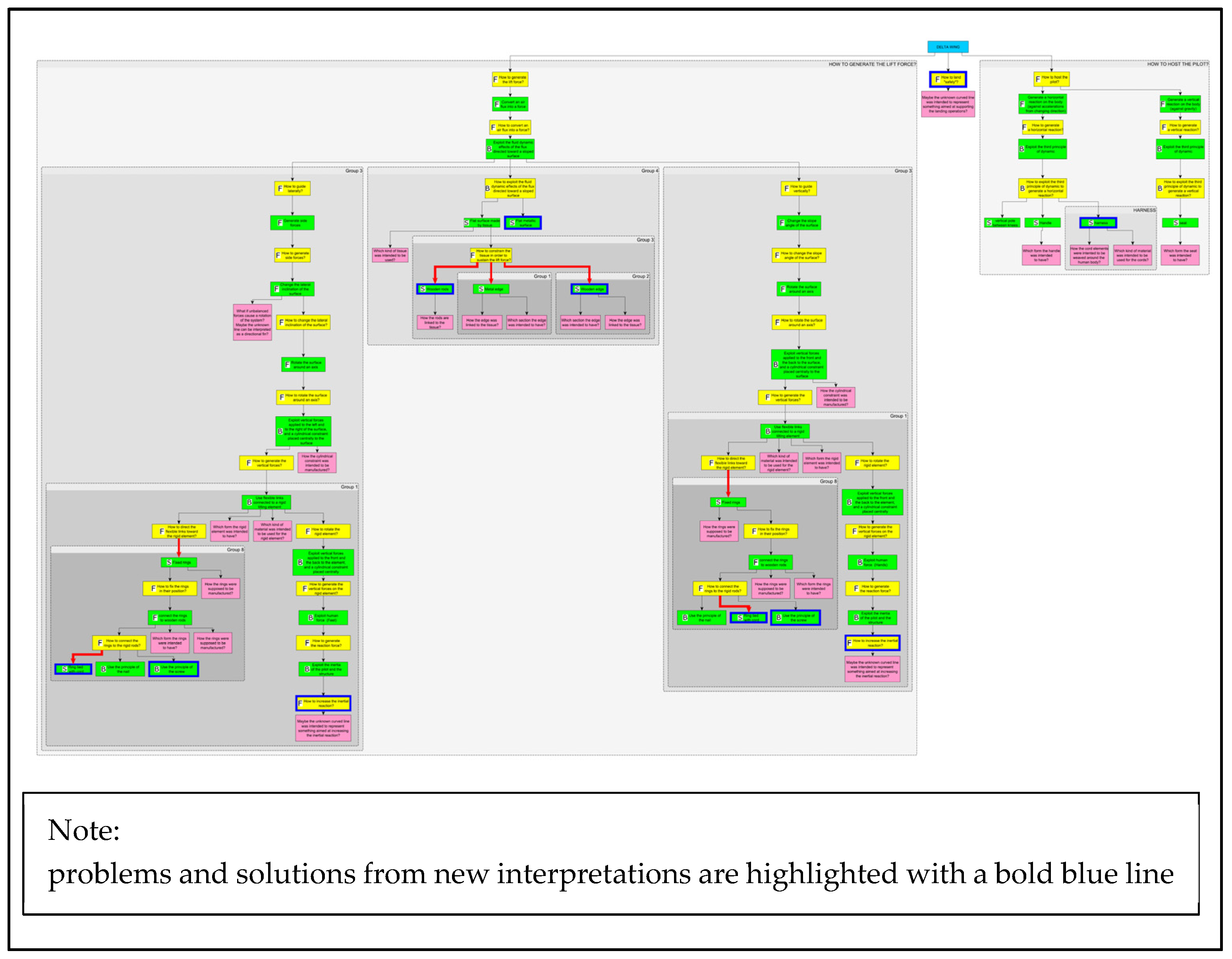
3.1. Problem–Solution–Network of Leonardo’s Delta Wing

The main functional problems considered for the delta wing are “How to generate the lift force?” and “How to host the pilot?” (i.e., resulting from Steps 3 and 4 in Figure 5). Indeed, any problem related to the control of the system is considered strictly dependent on the solutions adopted to solve the two main problems. Therefore, according to Figure 4, the PSN (Step 5 in Figure 5) started with a blue box indicating the delta wing project, followed by two yellow boxes, representing the main functional problems mentioned above (which were, then, tagged with the “F” letter, according to Table 1).
By starting from the two main problems, the first development of the PSN was performed by referring to the physical model produced in 2010 by the Museo Leonardiano of Vinci (Figure 3). In this way, the first ramifications of the net were realized, each of them providing a first set of problems. For some problems, of course, solutions were identified in the model of 2010, but the PSN allowed us to comprehensively represent them at the related abstraction levels. This abstract and structured representation supported the identification of possible alternative interpretations, i.e., different solutions for each problem, new problems and/or new information requests. In particular, the ambiguous curved line visible in Figure 2 under the whole system, was hypothesized (among the various alternatives) to be a sort of “landing device”. Therefore, a new main functional problem was formulated: “how to land safely?”, but no solution was stored in the PSN, since it is not clear how the “curved line” could actually work for landing purposes. Differently, a pink box was created, containing the information request (see Figure 6). This functional problem was added at the same PSN level of the two main functional problems. Indeed, it seems that in whatever way it works, the solutions are not directly influenced by how the system generates the lift force or how it hosts the pilot.
That of Figure 6 is only one example of the many new PSN boxes generated by the new possible interpretations hypothesized at different abstraction levels. The software used to realize the PSN is the Yed graph editor [26]. The number of additional problems and solutions (highlighted with a bold blue line), as well as the pink boxes, can be rapidly visualized in Figure 7 (for full readability please download the pdf version available at Supplementary Materials.
Besides the problems and solutions (respectively, yellow and green boxes) formulated by referring to the physical low-scale model built in 2010, two new problems were formulated, and eight new possible solutions were identified. Additionally, twenty-six information requests were added to both new and old problems and solutions. Indeed, some information requests are related to the new problems to be solved, while others are related to the need for a major understanding of the new proposed solutions, or can be related to the need for further details even for already adopted solutions.
A few examples are reported in the following subsections.

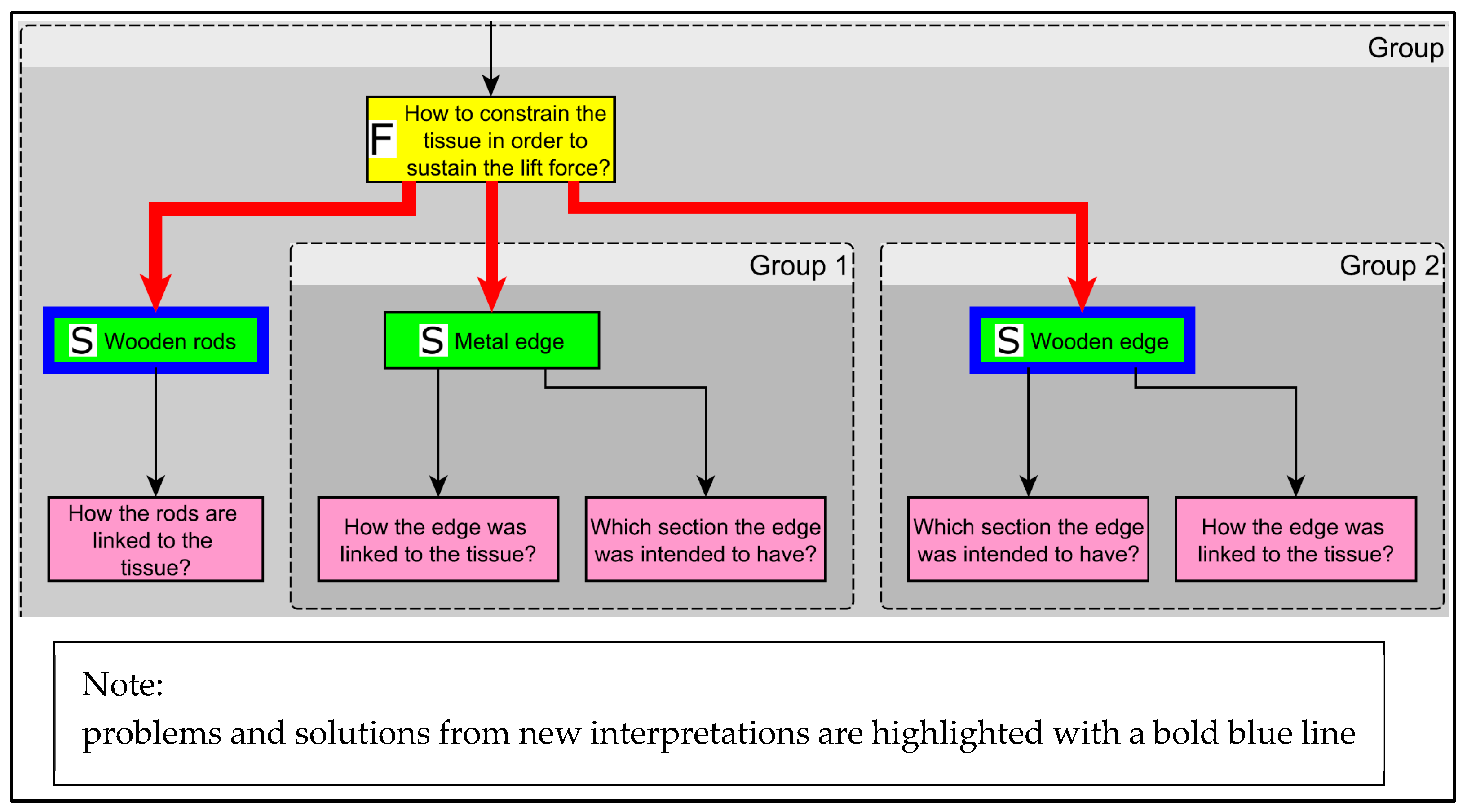
3.2. Example of Alternative Intepretations: How to Constrain the Tissue of the Wing

In Figure 8, an example is reported about possible alternative solutions for a problem, the related information requests, and the need for additional details (in terms of information requests) about an already adopted solution. The considered problem is that of “How to constrain the tissue (of the wing) in order to sustain the lift force?”. Indeed, Leonardo’s sketch did not provide any information about this.
In particular, wood-made alternatives were hypothesized for the constraining of the tissue, i.e., a wooden edge or wooden rods. The wooden edge, for example, could be realized by branches of the elder tree, e.g., with a diameter of about fifty-sixty millimiters. The elder tree was and still is widely diffused in Tuscany, and, once dried, is characterized by exceptional flexibility, good bending strength, and low weight. The other hypothesis is of the use of wooden rods, for example, of a rectangular section (with the longer side directed vertically), that can be manufactured in many ways. However, to realize a high-fidelity model, further research is needed to understand how to obtain the required section, length, and form with the technologies available in the considered period.
Additionally, it is possible to see that, due to the limited dimensions of the model of 2010, some details are still unclear for a high-fidelity reproduction in real scale. Indeed, the hypothesis considered in 2010 to determine the tissue was to use a metallic edge, on which the tissue was intended to be linked by means of strings. However, due to the small dimensions, it was impossible to reproduce a realistic manufacturing technique. Similarly, for the metallic edge, a commercial wire with a circular section was used (of about 1.5 mm diameter), while the actual section and the material to be used in a real-scale model (to be produced with the technologies of the period) is still unclear. Similarly, the actual binding technique to be used to connect the tissue to the edge was also hypothesized for the scaled model, but further studies are needed for a real scale high-fidelity model.

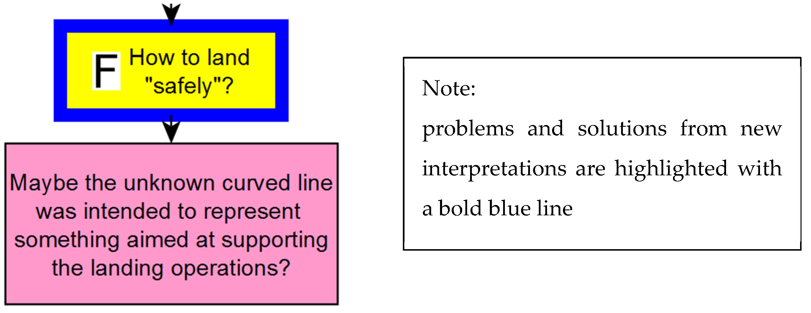
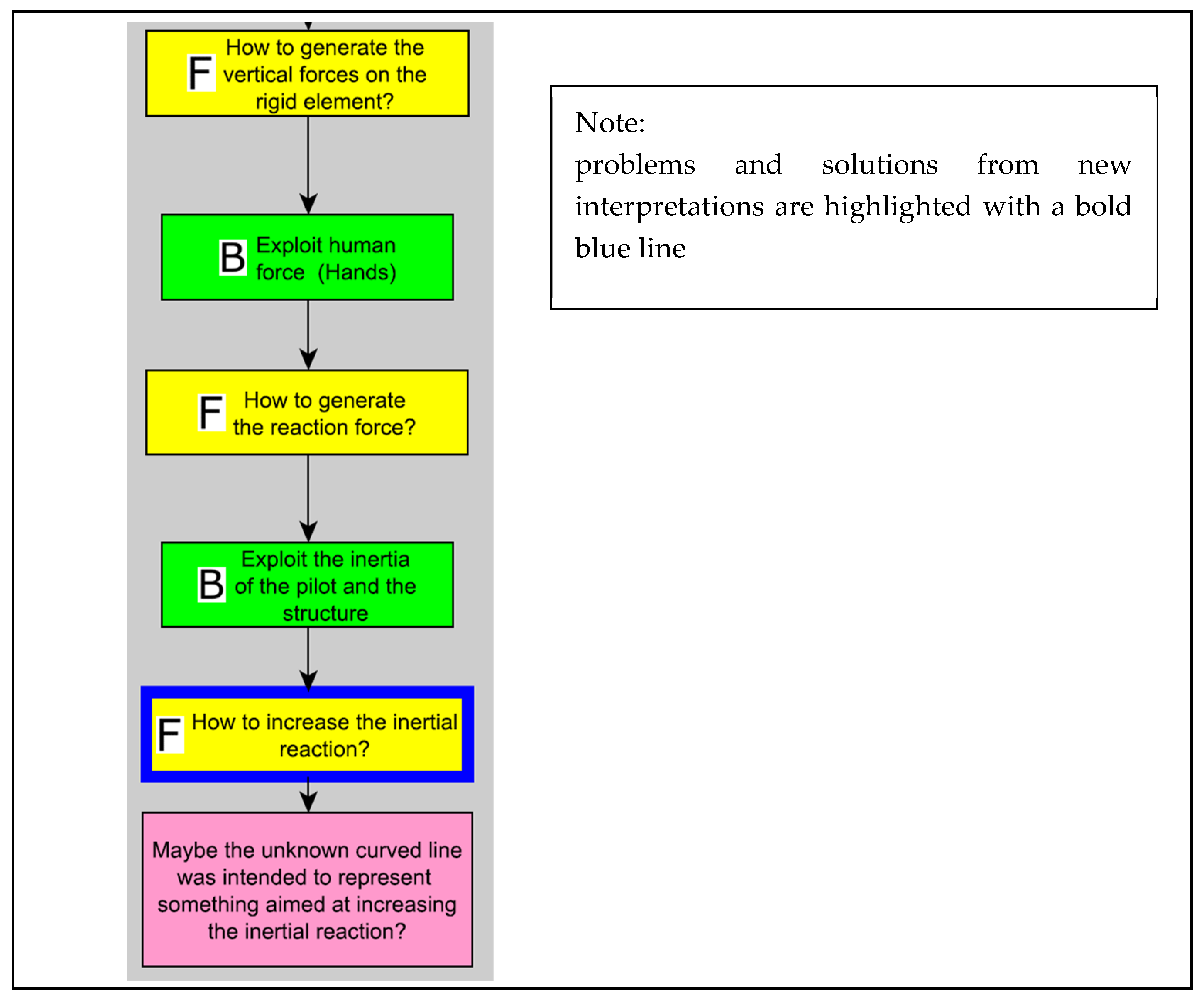
3.3. Example of Alternative Intepretations: Another Possible Purpose of the Ambiguous Line?

In Figure 9, an example is reported about an additional problem from a solution considered for the model built in 2010. More specifically, it was considered whether, when the pilot presses on the two command devices (the handling and the pedal), the reaction needed to move the wing (instead of the human him/herself) is given by the inertia of the system suspended under the wing, together with the mass of the pilot him/herself.
The problem could not appear to be so critical if focusing on a small-scale model, but if trying to design a real-scale high-fidelity system, the possible imbalance between the available inertia and the actual wind forces on the wing is quite evident. Therefore, as shown in Figure 9, a new PSN problem was formulated, about the need of increasing the magnitude of the inertial reaction.
A solution to the problem was not provided in the PSN, while an information request box was added. Indeed, it was hypothesized that the ambiguous line in Figure 2 could be somehow thought to be used as an additional mass to increase the inertial reaction of the system, i.e., a sort of stabilizer (similarly to the bar used by tightrope walkers).

3.4. Embodiment-Design Model

The information contained in the PSN allowed the identification of criticalities of the previous model, new possible interpretations, and related embodiment solutions. Figure 10 shows the embodiment design of a new possible model of the delta wing, thought to be manufactured in a real scale.
The most evident difference between the model of Figure 10 and that of Figure 3 is the presence of the lower curved part linked to a sort of skid. It was developed from the new possible interpretation introduced in Figure 6. Although the original sketch of Leonardo is limited to a curved line, the skid was added to obtain something reasonably working as a landing method. Additionally, it was supposed that the additional mass of such a detail could positively contribute to increasing the inertia reaction needed to generate the forces on the ropes. However, other new important features were modified and/or added.
As shown in view (a) of Figure 10, the transversal bar has now been placed over the tissue, leaving the lower surface of the tissue free from “aerodynamic” obstacles (see Figure 10, view (b)). The edge of the wing was thought to be realized with cylindrical wooden rods (e.g., from elder trees), fixed by means of windings (e.g., made by hemp ropes). The tissue was longitudinally fixed to the main rod, by means of an additional stick to be placed over the tissue (which can be fixed by means of metal nails). The wing surface is then placed between the two wooden elements. These new hypotheses were formulated thanks to the specific PSN boxes shown in Figure 8.
The pedal was kept almost unchanged, while the handle was sensibly modified. Indeed, a metallic handle with a reasonably rigid geometry to be obtained by an ancient blacksmith would be too heavy. Therefore, it was thought to realize a wooden handle, made by two planar elements joined by three metallic pins. One of the three pins, i.e., the central one, was thought to create the cylindrical joint between the handle and the vertical rod. This specific new hypothesis was formulated thanks to a specific PSN pink box, where a question arose about the possible materials to be used to manufacture the rigid elements used to guide the wing, i.e., the pedal and the handle [27].
Alternative hypotheses were preliminarily evaluated by the authors of this paper, who selected the preferred ones (Step 6 in Figure 5) and then built the preliminary CAD model (Step 7 in Figure 5).

4. Discussion

4.1. About the Obtained Results

The results obtained by the work described in this paper are twofold. On the one hand, a repeatable method is proposed to systematically design both physical and virtual models of ancient machines. It has been re-adapted from well-known methodological contributions available in the literature (e.g., [10,23,28,29]) and upgraded with the benefits given by recent contributions specifically developed for overcoming the acknowledged flaws of classic approaches [16,20]. In this way, it was possible to comprehensively manage the conceptual design of the model, and to keep track of the different information-gathering activities.
On the other hand, the application of the proposed approach to the real case study of Leonardo’s delta wing, allowed to hypothesize important improvements in the model currently available at the Museo Leonardiano of Vinci. In particular, the new model shown in Figure 10 was developed by considering a real-scale reproduction. The new features and the alternative solutions shown in this paper constitute the starting point for in-depth discussions among engineers, historians, and manufacturers, in order to develop all the required details. However, besides the result represented by the CAD model, a fundamental outcome is provided by the obtained PSN [27] where a new hypothesis, new details and new information-gathering activities are provided about the different working principles of each part of the system. The PSN is then expected to be updated after the discussions on the proposed CAD model and the decisions taken. For example, if the hypothesis of the skid were to be definitely accepted, it would be added as a solution to the problem represented in Figure 6.

4.2. Limitations of the Work and Research Hints

Some limitations can be highlighted for this work, both for the proposed method and for the case-study application.
Concerning the proposed systematic method, the first limitation is from a scientific point of view. Indeed, differently from methodological proposals specifically aimed at supporting engineering designers in industry-related activities, in this case, it is quite improbable to perform similar tests for validating actual effectiveness. More specifically, while for industry-related methods there are well-acknowledged sets of metrics to be used for assessing the effectiveness (e.g., from a creativity point of view [30,31,32,33,34,35,36]), it is difficult to understand what actually should be measured when designing models of ancient machines. One of the main issues in re-interpreting ancient technical documents is, of course, related to their subjectivity. However, subjectivity also heavily affects modern industrial design, and it is quite difficult (or even incorrect) to assert that it is the origin of negative results. Differently, subjective interpretations, ideas and approaches can increase the variety and the novelty of conceived solutions. There is not room in this paper to comprehensively discuss this, and this could be an open research question that could be investigated in future studies. Nevertheless, it can be stated here that there are non-negligible differences among modern-engineering design activities and the re-interpretation of ancient machines. The most important of them concerns the different purpose of the design activity: while a brand-new design activity should be performed by considering creative objectives (i.e., novelty and usefulness), this is completely not valid for ancient systems. Indeed, the model to be redesigned is not expected to be actually usable for the original purpose (e.g., to fly) and, of course, the machine is not new.
Accordingly, the method proposed here should be intended as a first attempt to provide potential support for scholars or museum staff involved in similar works, as well as a starting point for further research about the systematic interpretation and design of machines from ancient documents. Indeed, the need for systematic approaches and the related benefits for technological heritage studies are increasingly evident (e.g., [37,38]). Nevertheless, as usual in design science and practice, several different approaches can be used, adapted or invented from scratch in order to support the reconstruction of ancient devices. Indeed, although specific experimental activities can be performed in order to compare different methodological approaches, it is improbable to identify the panacea. This is a quite-well-acknowledged reality in design science [39]. Therefore, other design methods (e.g., [23,28,29,40,41]), problem-solving tools and theories (e.g. [42,43,44]) or even different reference definitions (e.g., about functions, [45]) can be used or re-adapted for this specific purpose.
Another limitation of the approach concerns the management of the different stakeholders involved in the interpretation and design processes. For the specific case study, simple brainstorming sessions among the authors were performed for each step of the process shown in Figure 5.
Concerning the delta wing model, the main limitations reside, of course, in the subjectivity of certain interpretations. However, due to the very limited information available, this kind of limitation can be ascribable to any other interpretation of the rough sketch (e.g., the curved line) provided by Leonardo. An additional limitation concerns the preliminary phase of the design activity, which needs to be continued in order to better understand how to manufacture specific details, e.g., the windings of the wing tissue, the materials to be used, the connection of the wing bars, etc. Further brainstorming sessions with historians, engineers and manufacturers are needed, thus leading to potential iterations of the process shown in Figure 5. Additionally, it is of course necessary to identify the next steps of the process in order to better frame the detailed-design activities (i.e., what is identified by Step 8 in Figure 5). This could lead to further iterations, which can lead to further improvements in the PSN (e.g., due to the need for further details about the system).

4.3. Expected Impact

The expected impact for society is strictly related to the new interpretation of the delta wing model of Leonardo. Indeed, this new model allows people to further understand how Leonardo da Vinci actually imagined human flight, centuries before the Wright brothers. Some specific flight machines devised by Leonardo are often acknowledged by most people. For example, the “macchina a decollo verticale” (vertical take-off machine) of Folio 0083v of Manuscript B of the Institut de France, is often referred as the “first helicopter”. Particular attention is also often paid to the sheet 1058v of the Codex Atlanticus, or to the Codex of the Birds Flight (studies about flapping wings). Differently, the new model of the delta wing proposed in this paper allows people to comprehensively understand how Leonardo imagined da Vinci’s glider. Surely, the interpretation proposed in this work is affected by subjectivity (as already highlighted in Section 4.2), but it provides a realistic “development” of the conceptual sketch provided by Leonardo.
The impact expected for academia is twofold. First, the systematic approach proposed in Figure 5 can be considered as a further application of systematic design methods. Therefore, design-science scholars can refer to this work as a useful reference for systematic design specifically tailored to the cultural heritage context. Concerning historians, the new model of the delta wing provides new detailed information for scholars interested in Leonardo’s flight studies.
Additionally, the new model shown in Figure 10 constitutes a valuable starting point for those museums or institutions that desire to build their own physical or virtual model of the machine. In addition, the process shown in Figure 5 provides them with structured support for designing any other model of ancient machines.

5. Conclusions

The work presented in this paper aimed at supporting scholars and museum staffs in performing systematic design of models of ancient machines. In particular, the well-known German systematic design procedure was re-adapted for the specific context, and some of the most recent improvements in terms of conceptual design tools and methods were also implemented. Well-defined steps characterized by both structured and non-structured iterations constitute the obtained procedure. The considered iterations are fundamental to ensure a gradual convergence of the task, by allowing required corrections and revisions.
The proposed approach was applied to the redesign of one of the most advanced concepts of a glider proposed by Leonardo da Vinci that, however, lacks those comprehensive descriptions that he included for other flight-related machines. This was considered a good case-study application for performing a first trial of the proposed method. Indeed, the absence of clear descriptions about the device required several discussions and iterations in order to obtain the final design of the model. A first physical model of the glider was designed by the authors in 2010, by following the main principles of systematic design, but without the direct application of a tailored method. Therefore, the already available knowledge about the first model was used here to build a first network of design problems and related solutions (according to the proposed procedure). This constituted the starting point of the conceptual design process, which led to new possible interpretations and allowed to better frame important details. The network of problems, solutions and information was then used to conceive an embodiment design of the glider, where important differences could be identified with the precedent model available at the Museo Leonardiano of Vinci. The differences are not limited to the structural details (e.g., the new handle or the new position of the wing tissue), but also consider new possible functions (e.g., the landing).
As comprehensively reported in the paper, this work presents some limitations which need to be highlighted, and that are expected to be a source of inspiration for further research. For example, it was not possible to use currently available experimental approaches in order to assess if and to what extent the proposed approach actually provides tangible advantages if compared with a non-structured approach. Indeed, in design research, there are well-acknowledged metrics and procedures that are normally used to assess or compare the efficiency of design methods and tools. However, these approaches are based on the concept of creativity, i.e., to assess the extent to which a method or tool actually can support the designer in conceiving new and useful designs. This is, of course, not valid for the redesign of models of ancient machines. Therefore, further research is needed to identify the set of parameters to be considered for comprehensive investigations about the effectiveness of the method proposed in this paper (and even others that could be proposed in the future).
As a further research avenue, strictly related to the development of the proposed approach, there is the need to proceed beyond Step 8 in Figure 5. Indeed, while the proposal presented in this paper primarily stops at a preliminary embodiment design, further steps and subsequent iterations are expected to be followed in order to obtain the final design and the related production documents.
Finally, by focusing attention on the obtained model of the glider, this can be considered one of the most detailed interpretation of that specific Leonardo da Vinci flying device, and can then be considered as a reference by scholars interested in this device for further research.

Supplementary Materials

The following supporting information can be downloaded at: https://www.mdpi.com/article/10.3390/heritage5030083/s1. The dataset [45].

Author Contributions

Conceptualization, L.F.; Methodology, L.F.; Validation, R.B.; Writing—Original Draft Preparation, L.F. and F.R.; Writing—Review & Editing, L.F., F.R. and R.B. All authors have read and agreed to the published version of the manuscript.

Funding

This research received no external funding.

Data Availability Statement

Not applicable.

Acknowledgments

We acknowledge the freely available resources about the Codex Madrid I, provided by the Biblioteca Nacional de España.

Conflicts of Interest

The authors declare no conflict of interest.

References

  1. Moon, F.C. The Machines of Leonardo da Vinci and Franz Reuleaux; Kinematics of Machines from the Renaissance to Machines of Leonardo Da Vinci (History of Mechanism and Machine Science); Springer: Berlin/Heidelberg, Germany, 2007. [Google Scholar]
  2. Galluzzi, P. Leonardo da Vinci: From the “elementi macchinali” to the man-machine. Hist. Technol. Int. J. 1987, 4, 235–265. [Google Scholar] [CrossRef]
  3. Hollister-Short, G. Relating to Leonardo da Vinci’ s Work on Textile Machines. J. Renaiss. 2007, 5, 77–115. [Google Scholar] [CrossRef]
  4. Innocenzi, P. The Innovators Behind Leonardo; Springer: Cham, Switzerland, 2019; ISBN 9783319904481. [Google Scholar]
  5. Padfield, G. Leonardo da Vinci Glider. Available online: https://www.liverpool.ac.uk/flight-science/fs/fshistory/leonardo/ (accessed on 18 April 2022).
  6. Laurenza, D. Leonardo on Flight. Aircr. Eng. Aerosp. Technol. 2008, 80. [Google Scholar] [CrossRef]
  7. Giacomelli, R. The Aerodynamics of Leonardo Da Vinci. J. R. Aeronaut. Soc. 1930, 34, 1016–1038. [Google Scholar] [CrossRef]
  8. Parra, R.B. Leonardo da Vinci Interdisciplinarity. In Proceedings of the 31st Congress of the International Council of the Aeronautical Sciences (ICAS 2018), Belo Horizonte, Brazil, 9–14 September 2018. [Google Scholar]
  9. Le Masson, P.; Weil, B. Design theories as languages of the unknown: Insights from the German roots of systematic design (1840–1960). Res. Eng. Des. 2012, 24, 105–126. [Google Scholar] [CrossRef] [Green Version]
  10. Pahl, G.; Beitz, W.; Feldhusen, J.; Grote, K.H. Engineering Design, 3rd ed.; Springer: London, UK, 2007; ISBN 9781846283185. [Google Scholar]
  11. Mossa, M. The recent 500th anniversary of Leonardo da Vinci’s death: A reminder of his contribution in the field of fluid mechanics. Environ. Fluid Mech. 2021, 21, 1–10. [Google Scholar] [CrossRef]
  12. Tarelko, W. Leonardo da Vinci—Precursor of Engineering Design. In Proceedings of the DS 36: DESIGN 2006, the 9th International Design Conference, Dubrovnik, Croatia, 15–18 May 2006; pp. 139–146. [Google Scholar]
  13. Güss, C.D.; Ahmed, S.; Dörner, D. From da Vinci’s Flying Machines to a Theory of the Creative Process. Perspect. Psychol. Sci. 2021, 16, 1184–1197. [Google Scholar] [CrossRef]
  14. E-Leo Digital Archive—Madrid Codex 1—Sheet 64r. Available online: https://www.leonardodigitale.com/en/browse/madrid-I/0064-r/ (accessed on 4 March 2022).
  15. Fiorineschi, L.; Barsanti, R.; Cascini, G.; Rotini, F. Application of Systematic Design Methods to Cultural Heritage Preservation. In Proceedings of the Heritech 2020, Florence, Italy, 14–16 October 2020. [Google Scholar]
  16. Fiorineschi, L.; Rotini, F.; Rissone, P. A new conceptual design approach for overcoming the flaws of functional decomposition and morphology. J. Eng. Des. 2016, 27, 438–468. [Google Scholar] [CrossRef]
  17. Purcell, A.T.; Gero, J.S. Design and other types of fixation. Des. Stud. 1996, 17, 363–383. [Google Scholar] [CrossRef]
  18. Jansson, D.G.; Smith, S.M. Design fixation. Des. Stud. 1991, 12, 3–11. [Google Scholar] [CrossRef]
  19. Crilly, N.; Cardoso, C. Where next for research on fixation, inspiration and creativity in design? Des. Stud. 2017, 50, 1–38. [Google Scholar] [CrossRef]
  20. Fiorineschi, L. Abstraction framework to support students in learning creative conceptual design. J. Eng. Des. Technol. 2018, 16, 616–636. [Google Scholar] [CrossRef]
  21. Vermaas, P.E.; Dorst, K. On the conceptual framework of John Gero’s FBS-model and the prescriptive aims of design methodology. Des. Stud. 2007, 28, 133–157. [Google Scholar] [CrossRef]
  22. Gero, J.S. Design Prototypes: A Knowledge Representation Schema for Design. AI Mag. 1990, 11, 26–36. [Google Scholar]
  23. Pugh, S. Total Design. Integrated Methods for Succesfull Product Engineering; Addison Wesley Publishing Company: Reading, MA, USA, 1991. [Google Scholar]
  24. Akao, Y. Quality Function Deployment: Integrating Customer Requirements into Product Design; Productivity Press: Cambridge, UK, 1990. [Google Scholar]
  25. Fiorineschi, L.; Frillici, F.S.; Rotini, F. Challenging COVID-19 with Creativity: Supporting Design Space Exploration for Emergency Ventilators. Appl. Sci. 2020, 10, 4955. [Google Scholar] [CrossRef]
  26. YWorks. YWorks Yed Graph Editor. Available online: https://www.yworks.com/products/yed (accessed on 4 April 2022).
  27. Fiorineschi, L. Problem-Solution-Network of the Leonardo da Vinci’s Glider. Mendeley Data 2022, 1. [Google Scholar] [CrossRef]
  28. Ulrich, K.T.; Eppinger, S.D. Product Design and Development, 5th ed.; Mc Graw Hill Irwin: New York, NY, USA, 2012; ISBN 9780073404776. [Google Scholar]
  29. Ullman, D.G. The Mechanical Design Process, 4th ed.; Mc Graw HIll: New York, NY, USA, 2010; ISBN 978-0-07-297574-1. [Google Scholar]
  30. Shah, J.J.; Smith, S.M.; Vargas-Hernandez, N. Metrics for measuring ideation effectiveness. Des. Stud. 2003, 24, 111–134. [Google Scholar] [CrossRef]
  31. Fiorineschi, L.; Rotini, F. Novelty metrics in engineering design. J. Eng. Des. 2021, 32, 590–620. [Google Scholar] [CrossRef]
  32. Fiorineschi, L.; Frillici, F.S.; Rotini, F. Refined metric for a-posteriori novelty assessments. J. Eng. Des. 2021, 33, 39–63. [Google Scholar] [CrossRef]
  33. Sarkar, P.; Chakrabarti, A. Assessing design creativity. Des. Stud. 2011, 32, 348–383. [Google Scholar] [CrossRef]
  34. Hennessey, B.A.; Amabile, T.M.; Mueller, J.S. Consensual Assessment, 2nd ed.; Academic Press: San Diego, CA, USA, 2011; Volume 1. [Google Scholar]
  35. Jagtap, S. Design creativity: Refined method for novelty assessment. Int. J. Des. Creat. Innov. 2019, 7, 99–115. [Google Scholar] [CrossRef] [Green Version]
  36. Lopez-Mesa, B.; Vidal, R. Novelty Metrics in Engineering Design Experiments. In Proceedings of the 9th International Design Conference, DESIGN 2006, Dubrovnik, Croatia, 15–18 May 2006; pp. 557–564. [Google Scholar]
  37. Geijo, J.M.; Sanchez-Lite, A.; Zulueta, P.; Sampaio, A.Z. Study of an “Artefact” of the Castilla Canal: Reconstruction of the Missing Machinery. Machines 2022, 10, 239. [Google Scholar] [CrossRef]
  38. Cascini, G.; Russo, D.; Nanni, R. A Contribution to History of Technology: Analyzing Leonardo’s Textile Machines and His Inventive Process by TRIZ Methods; Firenze University Press: Florence, Italy, 2004; ISBN 88-8453-221-3. [Google Scholar]
  39. Reich, Y. My method is better! Res. Eng. Des. 2010, 21, 137–142. [Google Scholar] [CrossRef] [Green Version]
  40. Kroll, E. Design theory and conceptual design: Contrasting functional decomposition and morphology with parameter analysis. Res. Eng. Des. 2013, 24, 165–183. [Google Scholar] [CrossRef]
  41. Shai, O.; Reich, Y. Infused design. I. Theory. Res. Eng. Des. 2004, 15, 93–107. [Google Scholar] [CrossRef]
  42. Altshuller, G.S. Creativity as an Exact Science; Gordon and Breach Science: Amsterdam, The Netherlands, 1984; ISBN 0677212305. [Google Scholar]
  43. Cavallucci, D.; Khomenko, N. From TRIZ to OTSM-TRIZ: Addressing complexity challenges in inventive design Denis Cavallucci, Nikolaï Khomenko. Int. J. Prod. Dev. 2007, 4, 4–21. [Google Scholar] [CrossRef]
  44. Nakagawa, T. A New Paradigm for Creative Problem Solving: Six-Box Scheme in USIT without Depending on Analogical Thinking. Available online: https://triz-journal.com/new-paradigm-creative-problem-solving-six-box-scheme-usit-without-depending-analogical-thinking/ (accessed on 2 January 2017).
  45. Vermaas, P.E.; Eckert, C. My functional description is better! Artif. Intell. Eng. Des. Anal. Manuf. 2013, 27, 187–190. [Google Scholar] [CrossRef] [Green Version]
Figure 1. The “delta wing” of Leonardo da Vinci, as it appears (in a mirrored view) in the codex Madrid 1, folio 64r [14].
Heritage 05 00083 g001
Figure 2. Non-exhaustive set of intuitive questions that scholar needs to face when trying to understand how the device works and can be built.
Heritage 05 00083 g002
Figure 3. Here is shown 1:20 scale model built in 2010 and currently visible at the Museo Leonardiano of Vinci (Italy). Image courtesy of Museo Leonardiano of Vinci.
Heritage 05 00083 g003
Figure 4. Generic PSN [16].
Heritage 05 00083 g004
Figure 5. Systematic approach for the interpretation of machines from ancient documents.
Heritage 05 00083 g005
Figure 6. New main function obtained from a hypothetical interpretation of the ambiguous curved line in Figure 2.
Heritage 05 00083 g006
Figure 7. Overall view of the PSN obtained in Step 5 of the process shown in Figure 5. Please note that the authors are aware of the unreadability of the contents of the boxes in this figure. For a full readable view, please download the pdf version freely accessible at this online dataset [27].
Heritage 05 00083 g007
Figure 8. Detailed view of the PSN branch related to tissue used to realize the wing.
Heritage 05 00083 g008
Figure 9. Detailed view of the PSN branch related to the generation of the forces needed to move the wing for guiding purposes. In particular, a new problem arose, simply by reasoning on what actually moves if the pilot presses on the control handle (or the pedal): is it the wing that moves, or the rest of the system under the cylindrical joints?
Heritage 05 00083 g009
Figure 10. Embodiment design of the new delta wing model. The weight of the structure is about 130 kg. View (a) allows view of the upper part of the wing. View (b) provides a sight of the lower surface of the wing. View (c) provides a side view of the system. Image (d) is the original sketch of Leonardo, reported in this figure to allow a direct comparison.
Heritage 05 00083 g010
Table 1. Additional PSN formalisms introduced by [20].
Type of BoxAbstraction LevelGraphical RepresentationDescription
ProblemFunction Heritage 05 00083 i001Problems about how to implement an action that the system is supposed to perform (e.g., “how to move the object?”)
Behavior Heritage 05 00083 i002Problems about how to exploit specific behaviors to implement a required function (e.g., “How to use gravity to move objects?”)
SolutionFunction Heritage 05 00083 i003Solution representing an action that the system could perform in order to solve a problem (e.g., “Move the object laterally”).
Behavior Heritage 05 00083 i004Solution representing a behavior that could be used to solve a functional problem (e.g., “Exploit the thermal expansion of metallic materials”).
Structure Heritage 05 00083 i005Solution representing the specific structure that can be used for implementing a function by exploiting specific behaviors (e.g., “Torque spring”).
ArrowsF to S passage Heritage 05 00083 i006When a solution to an “F” problem is formulated at the “S” level, thus neglecting the “B” level, the passage is highlighted by a bold red line
Publisher’s Note: MDPI stays neutral with regard to jurisdictional claims in published maps and institutional affiliations.

