Abstract
Machining chromium–nickel alloy steel is challenging due to its material properties, such as high strength and toughness. These properties often lead to tool damage and degradation of tool life, which overall impacts the production time, cost, and quality of the product. Therefore, it is essential to investigate early signs of tool damage to determine the effective machining conditions for chromium–nickel alloy steel, thereby increasing tool life and improving product quality. In this study, the early signs of tool wear were observed in a physical vapor deposition (PVD) carbide-coated tool (Seco Tools, Björnbacksvägen, Sweden) during the machining of X5CrNi18-10 steel under both dry and wet conditions. A finish turning operation was performed on the outer diameter (OD) of the workpiece with a 0.4 mm nose radius tool. At the early stage, the tool was examined from the functional side (f–side) and the passive side (p–side). The results indicate that dry machining leads to increased coating removal, more heat generation, and visible damage, such as pits and surface scratches. By comparison, wet machining helps reduce heat and wear, thereby improving tool life and machining quality. These findings suggest that a coolant must be used when machining chromium–nickel alloy steel with a PVD carbide-coated tool.
1. Introduction
The increase in the production volume, particularly in the metal cutting of chromium–nickel alloy steel, presents challenges for cutting tools due to the material’s high toughness. Thus, the likelihood of tool failure increases. The failure of a tool can lead to numerous challenges, including a decrease in product quality, unexpected machine breakdowns, increased vibrations, and higher cutting forces, all of which ultimately degrade the quality of the machined product and increase the production time.
Tool wear in turning processes develops through various stages, each defined by distinct wear mechanisms and their impact on the machining process. Understanding these stages is essential for enhancing tool longevity and sustaining machining effectiveness. The preliminary wear phase is when wear occurs as a result of the initial interaction between the tool and the workpiece. Higher wear rates and noticeable changes in tool geometry characterize this phase. Adhesion and diffusion are the primary wear mechanisms during this stage [1,2]. Another stage is the steady-state wear stage, in which the wear rate becomes stable, and tool wear advances at a more uniform and gradual rate compared to the early phase. Severe abrasion, adhesion, and even chipping and fracturing of the tool edge remain substantial in this stage; however, the wear rate is now more predictable and controllable [3]. The last stage is the accelerated wear stage. At this stage, the wear rate escalates fast, resulting in a decline of tool performance and surface quality with severe abrasion, adhesion, and even chipping or fracturing of the tool edge. It is essential to detect tool wear before it reaches the accelerated wear stage [4]. Several factors affect the tool wear, such as tool properties, material properties, machining parameters, and dry and wet machining conditions.
The cutting tool properties, such as tool sharpness, geometry, and whether the tool is coated or uncoated, can affect surface integrity by reducing friction and wear [5]. A coated tool generally offers better wear resistance and longer tool life, while uncoated tools can be resharpened, making them cost-effective. Yuan et al. [6] investigated tool sharpness, which has a significant impact on the minimum cutting thickness. Surface roughness, microhardness, residual stress, and dislocation density of the machined part surface vary with the cutting edge. Wang [7] mentioned that tool structure, material, and wear influence the machined surface integrity of titanium and nickel alloy. Prohászka et al. [8] highlighted that the thermodynamic properties of cutting tools and the cut material affect surface integrity, particularly with temperature changes in the machined material, causing phase transitions and variations in surface roughness. Yue et al. [9] noted that tool structure, material, and wear all influence the machined surface integrity of titanium and nickel alloys. It affects the geometrical characteristics, microstructure alteration, and mechanical properties. Xu et al. [10] investigated the rake angle, which has a significant influence on the machining process and surface integrity. A positive rake angle tool generates minimum surface deformation and less strain hardening on the workpiece.
To prevent these failures, continuous supervision is necessary during the turning process to determine the condition of the tool. The factors that lead to wear or degradation of the tool cutting edge include material removal, especially with a built-up edge (BUE), abrasion, diffusion, oxidation, and fluctuations in thermal and mechanical loads. Tool wear in machining is strongly affected by machining parameters, such as cutting speed, feed rate, and depth of cut, as well as by the machining environment, including dry and wet conditions. Higher cutting speeds and feed rates typically accelerate tool wear, limit tool life, and possibly degrade the surface quality and dimensional accuracy of the machined products [11]. Coolant is a crucial variable that affects tool performance during the machining of nickel-based alloys. Coolant reduces friction and cools the cutting zone, which helps protect the tool coating. Higher temperatures can lead to thermal cracking and wear [12,13]. A high-pressure coolant supply is particularly effective in chip evacuation and improves tool life by minimizing flank and crater wear [14]. During dry machining, in air or an oxygen-rich atmosphere, oxygen rapidly interacts with the freshly cut surface, resulting in the formation of a thin oxide layer. This layer impedes the adhesion of materials.
Additionally, cutting tools that readily react with oxygen may develop an oxide layer. This mechanism generates high cutting temperature, leading to tool wear and degradation [15,16,17]. Both actions alleviate stress in that region, preventing damage, such as notch development, and extending the longevity of the cutting tool [18].
This necessitates the regular monitoring of tool wear and the application of predictive maintenance solutions, such as tool condition monitoring systems, to enhance tool life and to maintain machining efficiency through the early detection of tool wear [19]. Studying tool wear over its full life span is a time- and energy-consuming process; however, a small-scale experiment provides an effective way to understand which machining condition is better.
This study aims to investigate and compare the early signs of tool wear under dry and wet machining conditions on PVD carbide-coated tools and X5CrNi18-10, chromium–nickel alloy steel. By focusing on early stages (preliminary wear phase) under dry and wet machining conditions, this study aims to provide insights into machining conditions that are more suitable for turning chromium–nickel alloy steel using PVD-coated carbide tools.
2. Materials and Methods
The selected tool insert for the experiment was DNMG150604-MF1 (CP500) from Seco Tools (Seco Tools, Björnbacksvägen, Fagersta, Sweden) [20]. It is made of carbide with a PVD coating, which improves wear resistance and cutting performance. The insert is used for the close tolerance, good finish, and increased tool life due to the coating. These inserts are used for longitudinal turning profiling and can be used for facing operations. The angle of 55 degrees provides less power consumption. This type also offers less vibration tendency and good accessibility, making it suitable for preventing vibration. The nose radius of the insert is 0.40 mm. The CP500 grade is a hard micro-grain grade primarily intended for finishing superalloys. The MF1 chip breaker is designed for medium-finishing operations, and machining using this insert is well-suited for achieving a good surface finish. The tool holder used in the experiment is DDJNL2525M15 from Seco Tools (Seco Tools, Björnbacksvägen, Fagersta, Sweden) [20]. The tool shank is 25 mm in height (H) and breadth (B), providing stability while turning. This insert is suitable for machining ISO M-type material.
Figure 1 shows an enlarged image of the tool insert, which will be used to analyze the early signs of damage further as well as wear on the tool. The PVD carbide coating is visible on the insert. Minor manufacturing defects, like deformation, can be noted on the edge of the tool.
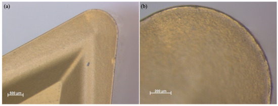
Figure 1.
PVD coated tool insert top view: (a) M = 25×, (b) enlarged M = 80×.
Similarly, Figure 2 presents the functional (f-side) plane view of the tool insert. This side is responsible for removing the initial material during the machining operation. A Discovery V8 microscope (Carl Zeiss Microscopy GmbH, Jena, Germany) was used to capture the images at two different magnifications, 25× and 80×. The enlarged pictures offer a clearer view of the wear on the tool.
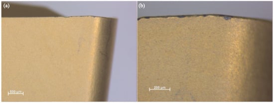
Figure 2.
PVD coated tool insert f-plane view: (a) M = 25×, (b) enlarged M = 80×.
The workpiece material used in this study is X5CrNi18-10, a grade of ISO M-type material. A cylindrical bar of Ø 45 mm and length 166 mm is used, portioned with a 4 mm groove length and 5 mm groove depth, as represented in Figure 3. This material is subjected to cutting forces, leading to heat generation, notch wear, and the formation of built-up edges on the tool. The ISO M material has a Kc1 variation (specific cutting force at 1 mm2 chip cross section) of 1800–2850 N/mm2. According to the manufacturer’s guidelines, the selected tool insert is well-suited for these material properties. The workpiece material has gained popularity in the automotive, marine, and aerospace industries due to its excellent corrosion resistance, superior mechanical properties, and versatility. This material is complex to machine and is widely used in the industry, making it essential to study the machinability and quality of machined products. The material has a significant impact on the tool, making it necessary to examine the tool wear on this material.
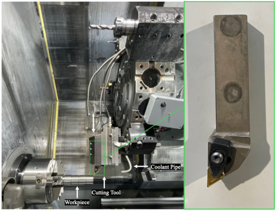
Figure 3.
Experimental Setup of Turning.
The machine used for performing the experiment is a HAAS ST-20Y CNC machine (Haas Automation, Inc., Leoben, Austria) [21]. The coolant used during the wet condition is a 5% CIKS HKF 420 oil emulsion. The cutting parameters were selected based on the workpiece’s characteristics and the cutting tool’s properties. The manufacturer’s guide for the tool insert provides suitable cutting parameters with spindle speed up to (Ns) 2000 rpm, feed (f) 0.1 mm/rev, and depth of cut up to 2 mm. In previous work, these parameters were examined, and it was concluded that the varying depth of cut plays a minor role in impacting the quality. The previous work parameters were used as a reference [22]. The spindle speed (Ns)) was varied at three levels: 1000 rpm (vc—141.4 m/min), 1500 rpm (vc—212.1 m/min), and 2000 rpm (vc—282.7 m/min). The spindle speed was chosen because it is easy to control during the operation. The operator can easily change it in the code. Feed (f) is varied at two levels, 0.1 and 0.3 mm/rev, and depth of cut (ap) is varied at one level. Two environments were chosen—dry and wet machining conditions.
After the experiment, the tool inserts were examined under a Stereo Discovery V8 microscope. The total length that one insert has moved during the experiment is 169.5 m. The early detection of tool wear can be noticed during this time.
3. Results
The results present the early detection of tool wear in chromium–nickel alloy steel under dry and wet conditions.
Figure 4a,b show the top view of the tool insert under dry machining conditions. The tool’s coating was excessively removed on the top side, severe crater wear from high friction, and chips during dry cutting can be noticed. It is also worth noting that a 0.5 mm depth of cut is excessive for the 0.4 mm nose radius tool. Several scratches can also be seen on the tool, due to chip flow. Pits are also noticeable in Figure 4b.
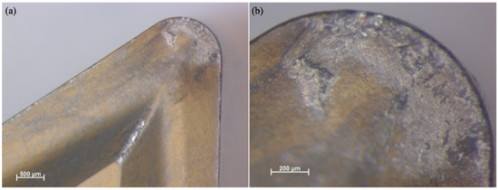
Figure 4.
Tool inserts top view after dry machining: (a) M = 25×, (b) enlarged M = 80×.
The f-side of the tool insert is shown in Figure 5a,b. It can be noticed on the dry machining condition insert that there are visible scratches and slight material removal due to friction. However, no wear is visible. The heat-affected zone (HAZ) is also visible in Figure 5a,b marked with red circles. Due to dry machining conditions, heat generation from friction can increase the HAZ. It can lead to tool degradation and reduced tool life. The surface shows early signs of wear. A comparison can be drawn between dry and wet machining conditions.
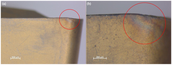
Figure 5.
Tool inserts f-side view after dry machining: (a) M = 25×, (b) enlarged M = 80×.
Similar effects can be seen on the p-side of the tool insert. Figure 6a,b show the insert used in dry conditions. The tool shows the visible scratches as minor thermal effects. Small material removal at the point of contact between the p-side and the surface can be observed, which is responsible for surface generation. The scratches are formed due to chip removal. The HAZ is also noticeable on the p-side in dry machining conditions.
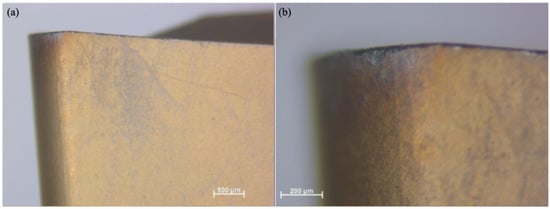
Figure 6.
Tool inserts p-plane view after dry machining: (a) M = 25×, (b) enlarged M = 80×.
Similarly, Figure 7a,b represent the tool insert’s top view under wet machining conditions. It can be noted that, compared to the tool insert from dry conditions, less coating was removed during wet machining conditions. There is minimal cratering and material removal, but the surface still has most of the coating. In addition, the tip of the tool does not have any mark of chip flow, which suggests that coolant is not only responsible for good machining but for preventing the chips from interacting with the tool.
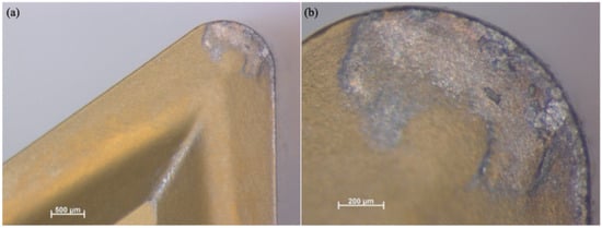
Figure 7.
Tool inserts top view after wet machining: (a) M = 25×, (b) enlarged M = 80×.
It can be understood from Figure 7a,b that an increase in tool life can be expected in wet machining conditions.
Although a top view provides suitable information regarding the early detection of tool wear, it is also essential to study the functional side (f-side) and the passive side (p-side) of the tool.
The front-side view of the tool insert for wet machining conditions is shown in Figure 8a,b. A small, localized HAZ zone is visible, marked with red circles. It is much smaller compared to dry machining conditions. The coating remains unscratched. No material loss can be seen.
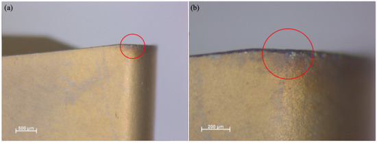
Figure 8.
Tool inserts f-side view after wet machining: (a) M = 25×, (b) enlarged M = 80×.
In wet machining conditions, the p-side surface appears smoother, with fewer scratches, due to the coolant flow, as shown in Figure 9. Slight wear, but not significant, is observed. In wet machining, the fact that there are no HAZs confirms that the coolant reduces the cutting temperature, protecting the tool material. It helps to maintain the quality of the product during the machining.
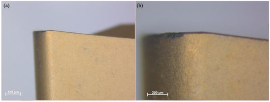
Figure 9.
Tool inserts p-plane view after wet machining: (a) M = 25×, (b) enlarged M = 80×.
The HAZ is more significant in dry machining conditions. The heat generation leads to deformation and a built-up edge, which overall affects the quality of the machined product.
4. Discussion
The microscopic inspection of the tool inserts under both machining conditions reveals essential signs of early tool wear, particularly in the turning of chromium–nickel alloy steel.
A top-view analysis reveals that dry machining conditions lead to increased wear, in the form of scratches, pits, and PVD carbide coating removal. This observation suggests that dry cutting can accelerate tool wear, particularly when the nose radius is smaller than the depth of the cut. The large heat generation and HAZ can be noticed in dry conditions. The measured HAZ length along the nose of the tool in dry cutting is 286.006 μm, and the length in wet machining conditions was 127.05 μm. Figure 10 highlights the comparison of the HAZ in dry and in wet machining conditions on the functional side. The HAZ in dry machining conditions is 2.25 times bigger than in wet machining conditions. The results suggest that there is higher heat generation in dry machining conditions, which can lead to oxidation and deformation in the tool, decreasing the tool life. In wet machining conditions, the coolant helps to dissipate the heat, thereby reducing the tool wear and improving the product quality.

Figure 10.
Comparison of the HAZ in tool inserts, f-plane view, M = 80×: (a) dry machining, (b) wet machining.
Similarly, a microscopic inspection of the insert used under wet machining conditions revealed no coating removal except at the point of contact between the tool and the workpiece. It also shows minimal wear at the point of contact. The coolant helps to reduce friction and cutting temperature, which is noticeable from a small HAZ in the insert. Machining in wet conditions can lead to longer tool life and improved surface quality. Minimal scratches on the tool coating show that coolant also protects the chips from interacting with the tool.
The f-side inspection of the tool provides better insights into the working area of the tool insert. Observations from the f-side of the tool indicate visible thermal damage and wear. In dry conditions, a clear HAZ is noticeable. These signs indicate that the tool has been exposed to high thermal stresses and accelerated wear, resulting in a decrease in surface quality. It also shows the early stage of tool wear. The p-side of the tool used in dry conditions shows similar results.
In wet machining conditions, the coating remains unaffected, with mainly surface scratches absent, and the affected zone is either very small or not visible at all. This clearly shows the coolant stabilizes the machining and helps in maintaining tool health.
The finding highlights that the early stage of tool wear is more visible in dry machining conditions due to the tool’s direct contact with the workpiece. Additionally, it was also observed that tool wear accelerated in dry machining conditions as the process continued; however, wet machining conditions delay significant tool wear.
5. Conclusions
This study highlights the importance of investigating the early signs of tool wear in the turning of chromium–nickel alloy steel under dry and wet machining conditions. The following conclusions can be drawn.
- Dry machining conditions result in high friction and larger heat generation, which leads to visible coating removal and larger heat-affected zones (HAZ) on the functional side of the tool.
- Wet machining conditions help with the heat dissipation during the tool–workpiece interaction. This results in a small HAZ, which overall increases the tool life. Additionally, it helps with the removal of chips, reducing chip–tool interaction, which leads to less coating removal.
- The HAZ length in dry machining conditions is 2.25 times larger than in wet machining conditions. This suggests that accelerated coating degradation due to excessive heat and friction leads to faster tool damage. By comparison, limiting thermal damage can lead to slower wear in the tool and ultimately increase tool life.
- The microscopic analysis suggests that a 0.5 mm depth of cut is unsuitable for a tool with a 0.4 mm nose radius. The depth of cut should be smaller than or equal to the nose radius of the tool in the finish turning operation.
This study offers insights into the optimal machining conditions for turning chromium–nickel alloy steel with PVD-coated carbide tools.
Author Contributions
Conceptualization, T.N. and I.S.; methodology, T.N.; software, I.S.; validation, C.F., I.S., and T.N.; formal analysis, I.S.; investigation, T.N.; resources, C.F.; data curation, I.S.; writing—original draft preparation, T.N.; writing—review and editing, C.F.; visualization, T.N.; supervision, I.S.; project administration, C.F.; funding acquisition, C.F. All authors have read and agreed to the published version of the manuscript.
Funding
Project no. 2020-1.2.3—EUREKA-2022-00025 has been implemented with support from the Ministry of Culture and Innovation of Hungary from the National Research, Development, and Innovation Fund, financed under the 2020-1.2.3-EUREKA funding scheme.
Data Availability Statement
The original contributions presented in the study are included in the article, further inquiries can be directed to the corresponding author.
Acknowledgments
Sincere thanks are extended to the University of Miskolc, Hungary, Faculty of Mechanical Engineering and Informatics, Institute of Manufacturing Science, for providing academic support, and to Interstop Kft., Miskolc, Hungary, for providing the necessary resources and technical assistance that significantly contributed to this research.
Conflicts of Interest
The authors declare no conflicts of interest.
Abbreviations
The following abbreviations are used in this manuscript:
| HAZ | Heat-Affected Zone |
| f-side | Functional Side of the Tool |
| p-side | Passive Side of the Tool |
| PVD | Physical Vapor Deposition |
References
- Diniz, A.E.; Machado, Á.R.; Corrêa, J.G. Tool Wear Mechanisms in the Machining of Steels and Stainless Steels. Int. J. Adv. Manuf. Technol. 2016, 87, 3157–3168. [Google Scholar] [CrossRef]
- Comici, M.V.; Giacomelli, I.; Stoicanescu, M. Studies on the Wear Behaviour of High Chromium Alloy Steels. RECENT—Rezult. Cercet. Noastre Teh. 2021, 22, 93–97. [Google Scholar] [CrossRef]
- Adaskin, A.M.; Vereshchaka, A.A.; Vereshchaka, A.S. Study of Wear Mechanism of Hard-Alloy Tools during Machining of Refractory Alloys. J. Frict. Wear 2013, 34, 208–213. [Google Scholar] [CrossRef]
- Akhtar, W.; Sun, J.; Sun, P.; Chen, W.; Saleem, Z. Tool Wear Mechanisms in the Machining of Nickel Based Superalloys: A Review. Front. Mech. Eng. 2014, 9, 106–119. [Google Scholar] [CrossRef]
- Salman, K.H.; Elsheikh, A.H.; Ashham, M.; Ali, M.K.A.; Rashad, M.; Haiou, Z. Effect of Cutting Parameters on Surface Residual Stresses in Dry Turning of AISI 1035 Alloy. J. Braz. Soc. Mech. Sci. Eng. 2019, 41, 349. [Google Scholar] [CrossRef]
- Yuan, Z.J.; Zhou, M.; Dong, S. Effect of Diamond Tool Sharpness on Minimum Cutting Thickness and Cutting Surface Integrity in Ultraprecision Machining. J. Mater. Process. Technol. 1996, 62, 327–330. [Google Scholar] [CrossRef]
- Wang, B. The Future of Manufacturing: A New Perspective. Engineering 2018, 4, 722–728. [Google Scholar] [CrossRef]
- Prohászka, J.; Horváth, M.; Mamalis, A.G.; Nyirö, J. Effect of Cutting Tools and Cut Materials on Integrity of Mirror Surfaces. Surf. Eng. 2006, 22, 294–298. [Google Scholar] [CrossRef]
- Yue, C.; Gao, H.; Liu, X.; Liang, S.Y.; Wang, L. A Review of Chatter Vibration Research in Milling. Chin. J. Aeronaut. 2019, 32, 215–242. [Google Scholar] [CrossRef]
- Xu, D.; Ding, L.; Liu, Y.; Zhou, J.; Liao, Z. Investigation of the Influence of Tool Rake Angles on Machining of Inconel 718. J. Manuf. Mater. Process. 2021, 5, 100. [Google Scholar] [CrossRef]
- Kuntoğlu, M.; Aslan, A.; Sağlam, H.; Pimenov, D.Y.; Giasin, K.; Mikolajczyk, T. Optimization and Analysis of Surface Roughness, Flank Wear and 5 Different Sensorial Data via Tool Condition Monitoring System in Turning of Aisi 5140. Sensors 2020, 20, 4377. [Google Scholar] [CrossRef] [PubMed]
- Fazullin, D.D.; Mavrin, G.V.; Fazullina, L.I. Disposal of Spent Coolant by Dynamic Membrane. Lect. Notes Mech. Eng. 2021, 2, 1314–1322. [Google Scholar] [CrossRef]
- Silva, L.R.; Corrêa, E.C.S.; Brandão, J.R.; de Ávila, R.F. Environmentally Friendly Manufacturing: Behavior Analysis of Minimum Quantity of Lubricant—MQL in Grinding Process. J. Clean. Prod. 2020, 256, 103287. [Google Scholar] [CrossRef]
- Katoh, T.; Ohmori, S.; Maeda, T.; Kakumitsu, T.; Okuda, K.; Sekimoto, M.; Morigo, C. Effect of High-Pressure Coolant Supply on Chip-Breaking and Tool Wear in Machining of Stainless Steel. Key Eng. Mater. 2015, 656–657, 226–230. [Google Scholar] [CrossRef]
- Khrais, S.K.; Lin, Y.J. Tribological Influences of TiAlN Coating on Tool Wear for High-Speed Dry and Wet Machining of Steels. Am. Soc. Mech. Eng. Manuf. Eng. Div. MED 2008, 15, 843–848. [Google Scholar] [CrossRef]
- Soković, M.; Kopać, J.; Dobrzański, L.A.; Adamiak, M. Wear of PVD-Coated Solid Carbide End Mills in Dry High-Speed Cutting. J. Mater. Process. Technol. 2004, 157–158, 422–426. [Google Scholar] [CrossRef]
- Khrais, S.K.; Lin, Y.J. Wear Mechanisms and Tool Performance of TiAlN PVD Coated Inserts during Machining of AISI 4140 Steel. Wear 2007, 262, 64–69. [Google Scholar] [CrossRef]
- Khamsehzadeh, H. Behaviour of Ceramic Cutting Tools When Machining Superalloys. Ph.D. Thesis, University of Warwick, Coventry, UK, 1991. [Google Scholar]
- Maia, L.H.A.; Abrão, A.M.; Vasconcelos, W.L.; Júnior, J.L.; Fernandes, G.H.N.; Machado, Á.R. Enhancing Machining Efficiency: Real-Time Monitoring of Tool Wear with Acoustic Emission and STFT Techniques. Lubricants 2024, 12, 380. [Google Scholar] [CrossRef]
- Seco Tools. Available online: https://www.secotools.com/article (accessed on 1 March 2025).
- HAAS CNC. Available online: https://www.haascnc.com/ (accessed on 1 March 2025).
- Felhő, C.; Namboodri, T. Statistical Analysis of Cutting Force and Vibration in Turning X5CrNi18-10 Steel. Appl. Sci. 2024, 15, 54. [Google Scholar] [CrossRef]
Disclaimer/Publisher’s Note: The statements, opinions and data contained in all publications are solely those of the individual author(s) and contributor(s) and not of MDPI and/or the editor(s). MDPI and/or the editor(s) disclaim responsibility for any injury to people or property resulting from any ideas, methods, instructions or products referred to in the content. |
© 2025 by the authors. Licensee MDPI, Basel, Switzerland. This article is an open access article distributed under the terms and conditions of the Creative Commons Attribution (CC BY) license (https://creativecommons.org/licenses/by/4.0/).