1. Introduction
A radio-frequency quadrupole (RFQ) is the most used injection structure in linear particle accelerators for massive particles like protons and heavier ions. This is due to the fact that it is the only structure that can accept a continuous flow of low-energy particles (keV) and accelerate them into the MeV range. In this structure, a single RF field provides all the different functionalities required for proton acceleration.
Simultaneous with the acceleration, the RF field confines the particles and bunches the continuous beam into a collection of macroscopic packets. The design principles were first presented by Kapchinski and Tepliakov in 1969 [
1], and the first operational RFQ was demonstrated at LANL in 1980 [
2]. Geometrically, it is a resonant cavity with a cylindrical symmetry divided in four lobes or vanes resembling a clover-like figure (
Figure 1). This structure enhances the excitation of the TE210 mode, with the quadrupole symmetry providing a continuous, alternating quadrupole along the RFQ’s axis. Due to the shape of the section, the magnetic field dominates at the lobes, and the electric field dominates in the central channel, where the particles will travel and accelerate. This provides pure electrical focusing that is not dependent on the particle velocity and is well suited for massive particles like protons.
Typical proton RFQs use a frequency in the range from 300 to 400 MHz such as, for instance, the 324 MHz FETS RFQ at RAL [
3] or the 352.2 MHz LINAC4 RFQ developed at CERN as a part of the LHC injector [
4]. The use of higher frequencies allows for the reduction of the RFQ size at the expense of acceleration efficiency. In 2016, CERN built the first compact proton RFQ at 750 MHz [
5]. The final RFQ for our project is also intended to work at 750 MHz and provide proton acceleration from 30 keV to 4.5 MeV in a compact 1.5 m long structure [
6,
7]. As proof of concept, to check the design procedure and to study mechanical feasibility, a cold model was built, which is a shorter version (0.5 m) intended to work at low power (mW) and without a vacuum (
Figure 2).
The paper is divided into two main sections, plus a conclusion section. The
Section 2 presents the RFQ cold model we have designed and tested for this study and its electromagnetic eigenmode analysis. The
Section 3 reports the experimental results. In particular, the new power injection scheme is presented, including power combination and mode excitation or avoidance with the help of the relative phase between the injected signals.
2. Materials and Methods
The RFQ’s design process has to fulfill some specific requirements from the EM point of view. The TE210-like quadrupolar mode has to be excited at the operating frequency, maximizing the quality factor Q and avoiding undesired modes near the operating frequency, as is the case of dipolar modes such as TE110. A common way to couple the RF power in proton RFQs has been the use of loop-couplers inserted into the mid-section of the RFQ lobes. This technique has been demonstrated to be reliable and effective but introduces a significant perturbation into the lobe that can be more noticeable when dealing with compact structures. We propose a double symmetrical RF injection scheme using direct transition from the coaxial cable to the RFQ by connecting the inner coaxial conductor into the RFQ vane body, as shown in
Figure 3.
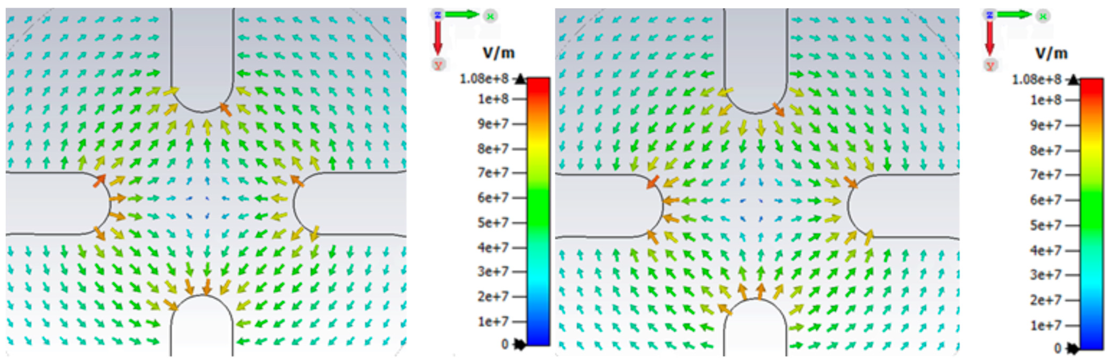
As a result, the insertion of metallic parts into the lobe itself is avoided, resulting in minimized lobe field perturbations. Note that, in this way, the transversal electrical fields are directly excited through the vanes. Moreover, by combining two couplers connected to opposed vanes at a given transversal plane of the RFQ, it is also possible to excite the quadrupolar mode while avoiding the dipolar modes. This coupling avoids introducing objects into the cavity that would perturb the designed fields. From an electromagnetic point of view, it can be pictured as a transition from a TEM mode in the coaxial to a TE mode in the cavity (
Figure 4).
A section of a compact RFQ has been designed and manufactured to serve as a cold model. This is a realistic proof-of-concept model intended to be tested under small-signal conditions. When analyzing the RFQ resonances using eigenmode analysis, two first modes appear, corresponding to quasi-degenerated dipolar modes (TE110) along the
Y and
X axis (
Figure 5 and
Figure 6).
The modes are not at the same frequency because the symmetry is not perfect, and the signal injection is made in the X axis. Neither of these modes are appropriate for confining the beam, as they only act in one of the axes.
The third mode (TE210) is the one with quadrupole symmetry (
Figure 7), which acts in both axes and has the correct shape for confining the beam. It alternates focusing periods in the X and Y direction along the length of the RFQ, providing a purely electrical focus. At higher frequencies, one can find the same three modes (dipolar Y, dipolar X, and quadrupolar) repeated as harmonics. In these modes the field intensity changes as length increases, becoming zero at the nodes. The most problematic modes are the harmonics of the dipolar modes, which lay close (+/−10%) to the main quadrupolar mode, and can overlap with it, especially if the structure is long. The reason being that the frequency of the harmonics decreases as the length increases. The coupling solution can be tested through frequency domain simulation, injecting the signal from the coaxial cables to the RFQ through the ports and implementing a direct coaxial-like electric coupling (
Figure 3).
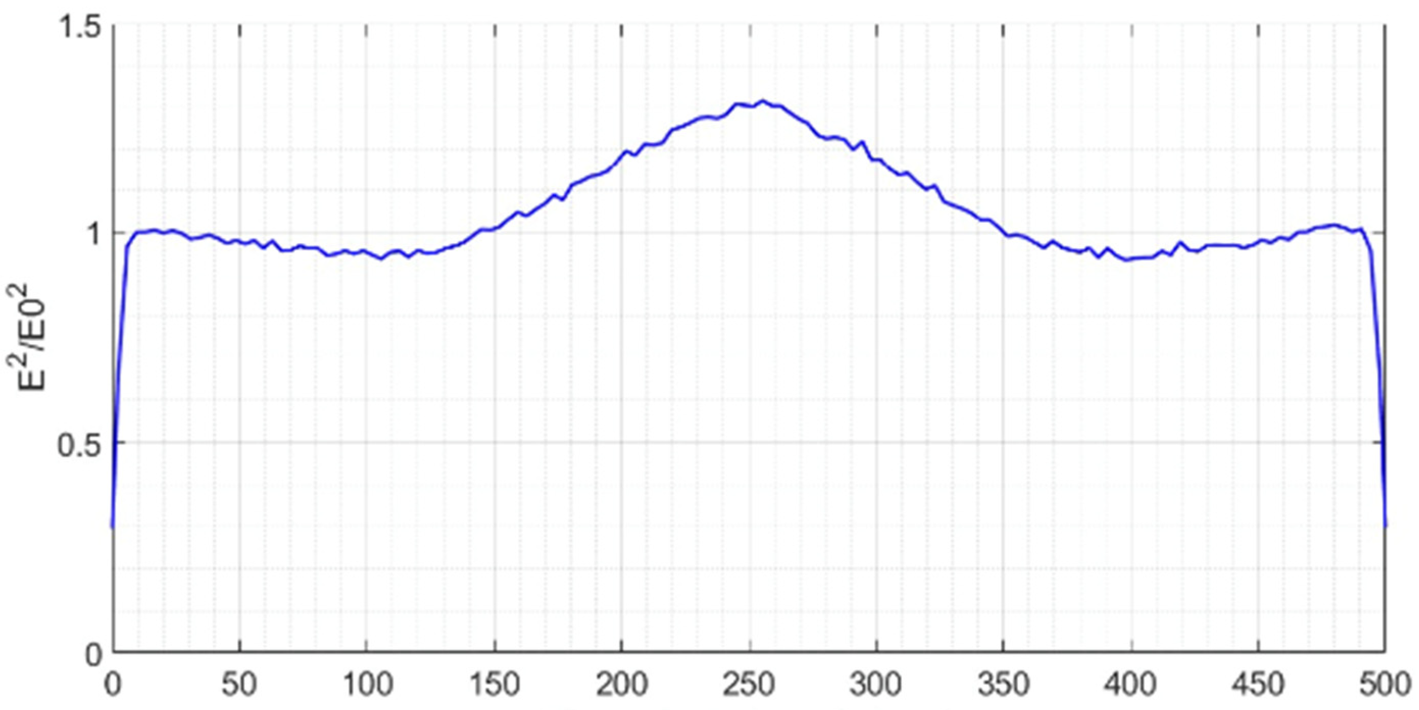
The field flatness along the
z-axis is essential for the proper operation of an RFQ.
Figure 8 shows a zoomed view of the normalized field profile obtained in one lobe near the axis of the structure. The field shows a maximum at the center, corresponding to the location of the input power ports. Two small valleys, symmetrical with respect to the center, can also be observed at the position in which the tuners are located. Questions as to how this can affect acceleration efficiency or bunching effectiveness are out of the scope of this work, but the field flatness is obtained through careful design optimization. We have also avoided thermo–mechanical studies since this work concerns an RFQ cold model. When designing an operational high-power RFQ structure, power dissipation in the vane tips is a critical issue, and the power injection regions have to also be carefully studied. Using a pair of RF ports per RFQ section is helpful in managing thermo–mechanical issues, with the possibility of adding more power ports along the structure if needed [
7].
3. Results and Discussion
In order to check the appearance of the different modes, as well as their excitation amplitude, a setup is arranged like in
Figure 9. The signal from a VNA (Vector Network Analyzer) is divided into two signals with equal amplitudes. One of them goes through a variable phase shifter, which allows control of the relative phase between the two RFQ input ports, and the other is connected directly. Finally, the signal is picked, employing an antenna located near the beginning of the structure. This picked signal goes back to the VNA.
For the first measurement, the phase difference is kept at 0, and a frequency sweep is performed. The transmission coefficient as a function of frequency is plotted in
Figure 10. As in the simulations, the first two modes to appear (dipolar modes TE110) are quasi-degenerated. Afterwards, it comes the predominant mode (the quadrupolar TE210 mode). Finally, the harmonics of those three modes are observed.
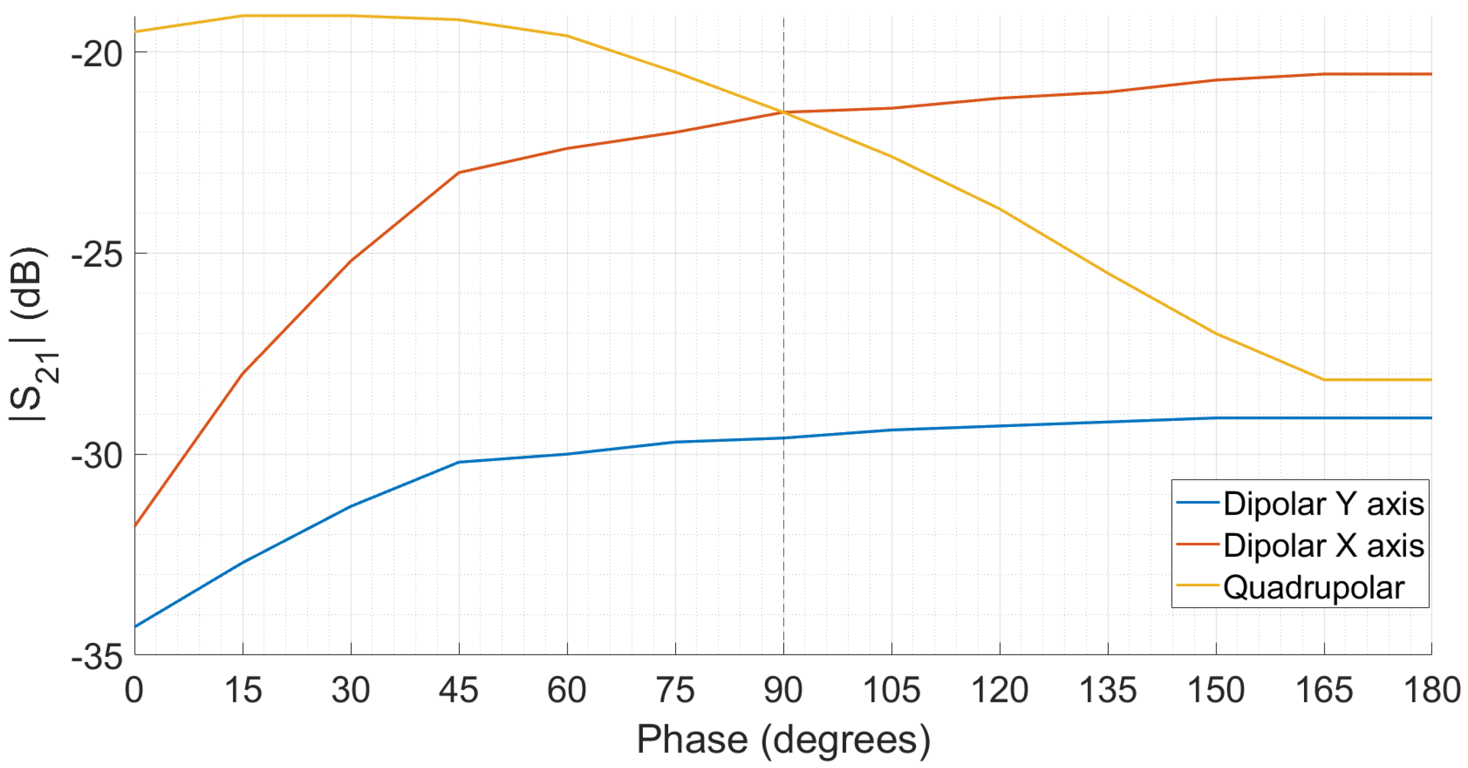
As there are two ports to inject the signal, a degree of freedom exists, which is the relative phase between them. If the phase is the same, the symmetry with the quadrupolar mode (
Figure 7) is maximum. However, as the phase difference increases, the coupling with the dipolar modes (
Figure 5 and
Figure 6), in which they are completely out of phase, increases. This result is found experimentally in
Figure 11, and it agrees with simulations. Moreover, halfway between being in phase and out of phase, at 90°, the excitation amplitude of the dipolar mode X and the quadrupolar mode become equal.
The mode separation between the dipolar TE110 modes and the quadrupolar mode has been found to be around 45 MHz. Regarding some other measured higher order modes in
Figure 10, the most significant observations were found at around 1.1f
0, with an amplitude that was 15 dB lower than the quadrupolar one, and even further at 1.74f
0 with an associated amplitude similar to the fundamental quadrupolar mode.
The quality factor (Q) and coupling coefficients have been measured. Following Ginzton’s impedance method as described in [
8,
9], it is possible to obtain both Q
0 (unloaded quality factor) and Q
L (loaded quality factor) with high precision. The method has been applied here twice, once for each port as in [
10], to obtain Q
0,1, Q
L,1, as well as Q
0,2 and Q
L,2. Then, the total external quality factor (which only accounts for external losses) is found by combining the external losses at each port. Finally, the total external losses are decoupled from the load quality factor (accounting for both losses in the cavity and the external circuitry) to obtain the desired unloaded quality factor Q
0. The results are summarized in
Table 1.
Note that the measured value Q
0 ≈ 1100 is significantly lower than Q
0 ≈ 8000 found in the simulation for this structure when using ideal copper at room temperature. However, as the prototype is not maintained under vacuum, surface oxidation is inevitable and, although it is only superficial, the RF high frequency currents are located in the first μm due to the skin depth. As a consequence of this oxidation, the effective conductivity is shown to be σ ≈ 1.1·× 10
6 (Ωm)
−1 in our prototype, compared to a value of σ = 5.8 × 10
7 (Ωm)
−1 employed in the simulations. This result agrees with the conductivity decreases reported in the literature for copper [
11]. On the other hand, in our experiments we have directly connected the external coaxial cables to the RFQ structure, thus avoiding the use of a specific coupler design for impedance matching improvement. The resulting coupling factor is β ≈ 0.2 which corresponds to an under-coupling situation.
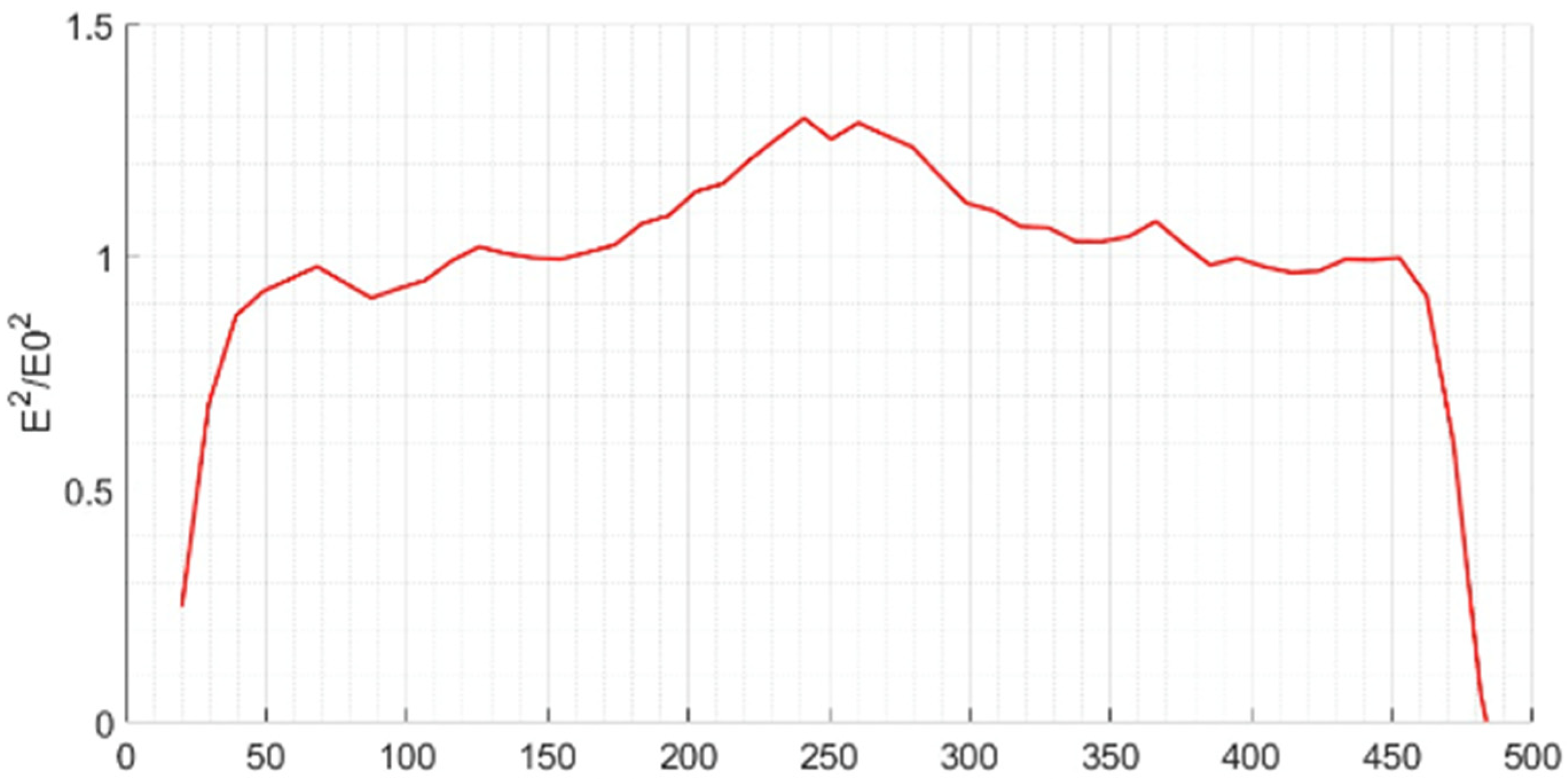
Finally, the field along the
z-axis has been measured in the same location and conditions as in the simulation results shown in
Figure 8. The experimental normalized electrical field in
Figure 12 shows a very good agreement with the simulations, except when approaching the ends of the structure. The fields there undergo a faster decrease that can be produced by the coupling of the bead that was employed in the measurements with the metallic walls, thus producing a local increase in the capacitance, which reduces the impedance and thus, the electrical field amplitude.
4. Conclusions
Building an operational RFQ cavity for proton particle acceleration involves an intricate electromagnetic design of its geometry and excitation ports. The use of computational parametric models, as well as the manufacturing of low power prototypes is essential to predict the future behavior of the final structure. In the work presented, some experiments were performed in order to characterize the EM properties of the cavity. The spectrum of a typical RFQ has been reproduced, consisting of two spurious TE110 dipolar modes, one fundamental TE210 quadrupolar mode, and its harmonics. The prototype employs an innovative approach which delivers the power via electric coupling. It consists of two coaxial-like entrances from opposite sides of the RFQ, whose relative phase can be adjusted in order to maximize the excitation amplitude of the desired TE210 mode and simultaneously minimize the excitation amplitude of the TE110 dipolar modes. This fact perfectly matches the field symmetries observed in the eigenmode simulation. It has been demonstrated, both by measurements and simulations, that this new proposed power injection design is able to excite the required resonant fields in the RFQ for appropriate simultaneous beam focusing, without the insertion of metallic obstacles into the RFQ lobes.


 ,
, 


