1. The ICARUS Detector at Fermilab
The ICARUS-T600 liquid argon (LAr) time projection chamber (TPC) detector [
1] currently takes data at a shallow depth as the far detector of the Short Baseline Neutrino (SBN) program at Fermilab [
2], searching for sterile neutrinos with muon and electron neutrinos from the 0–2 GeV Booster Neutrino Beam (BNB) and the off-axis 0–5 GeV Neutrinos at the Main Injector (NuMI) beam. In recent years, several experiments reported evidence of anomalous neutrino oscillations (e.g., LSND [
3] and MiniBooNE [
4]) suggesting the existence of a fourth sterile neutrino state associated with a large
∼1
mass splitting, which would produce oscillations at short baselines. Several constraints on sterile neutrinos exist, including ICARUS measurements from data collected at the INFN Gran Sasso National Laboratories in Italy [
5]. ICARUS is also pursuing a rich stand-alone program focused on neutrino oscillations, cross-sections, and going beyond the standard physics model.
The ICARUS detector, after operating deep underground at the Gran Sasso Laboratories until 2013, underwent an intense overhaul at the CERN and INFN laboratories [
1] before starting collecting data at Fermilab in 2020. Refurbishing activities improved the cryogenics and purification systems, implemented new TPC read-out electronics, and upgraded the liquid argon light detection system with respect to the LNGS configuration [
1,
6].
This detector consists of two identical modules filled with 476 t of active liquid argon, each hosting two 1.5 m-drift LAr-TPCs separated by a shared cathode with ∼58% transparency at a nominal 500 V/cm electric drift field (
Figure 1). The TPC anodes consist of three readout wire planes with 3 mm pitch and 3 mm apart, oriented at 0 and ±60°, respectively, with respect to the BNB direction, where the first two Induction-1 and Induction-2 planes measure the ionization charge non-destructively, and the last Collection plane collects the charge.
Due to the shallow depth, ICARUS faces a challenging ∼11 kHz cosmic ray rate. To reduce the hadron and photon cosmic ray component, a 3 m concrete overburden was deployed. In addition, the detector is surrounded by a segmented plastic scintillator Cosmic Ray Tagger (CRT) system, providing timing of crossing particles.
Scintillation light produced by ionizing particles in liquid argon [
7,
8] is detected by 360 8″ photo-multiplier tubes (PMT) located behind the TPC wire planes [
9], with 90 PMTs per TPC, providing a prompt signal used for the trigger system and for timing purposes.
The evolution of the trigger system through the initial physics runs, from Run1 (9–12 June 2022), through Run2 (20 December 2022–10 June 2023), to recent physics runs, is described in the following.
2. The ICARUS Trigger System
The ICARUS trigger system is online, fully implemented on hardware and FPGA programmable logic, and based on coincident light signals.
Light signals collected by the PMTs are continuously digitized and stored in 10 µs memory buffers by 500-MSa/s 16-channel digitizers [
9], which also acquire reference timing signals from the accelerators. The 10 µs PMT acquisition window includes 3 µs of pre-trigger and 7 µs of post-trigger to accommodate for both the fast (
ns) and slow (
µs) components of scintillation light in liquid argon [
7]. Each digitizer records signals from 15 PMTs in a 3 m longitudinal TPC slice, pairing them into 7 pairs (in logical OR) and 1 singlet low-voltage differential signal (LVDS) outputs activated by a light signal exceeding a digital 13-photoelectron threshold.
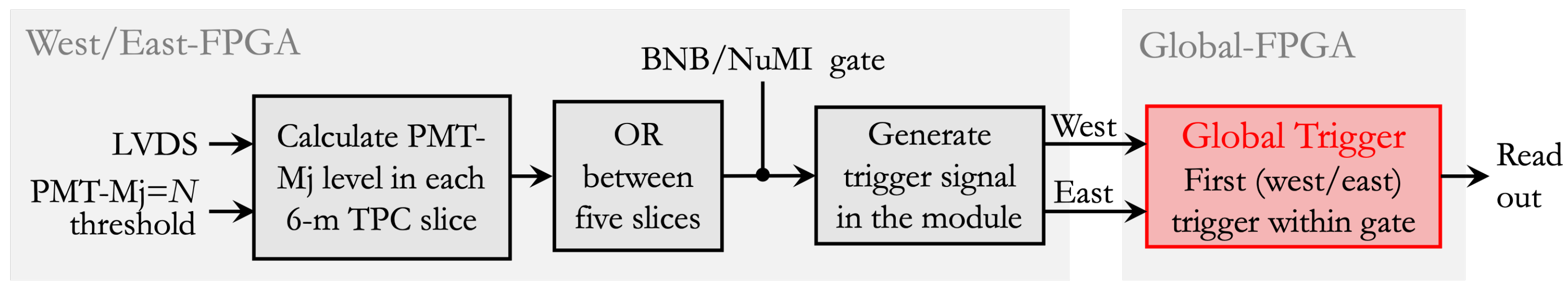
The digital LVDS signals in the west and east modules are fed into the trigger electronics, where two FPGAs (“West” and “East”) evaluate at each clock cycle (25 ns) the LVDS patterns in the two modules according to a pre-defined trigger logic. The third “Global” FPGA combines the BNB and NuMI proton extraction signals with the West- and East-FPGA evaluation outcome, electing the first trigger of the two as the global trigger.
After the global trigger is issued, the Global-FPGA alerts the trigger electronics to start the readout of the TPC for 1.6 ms, of the CRT for 6 ms, and of all PMT signals for 26 µs around the trigger. The PMT acquisition window is enlarged from 10 µs to 26 µs for triggers in coincidence with the beam gate.
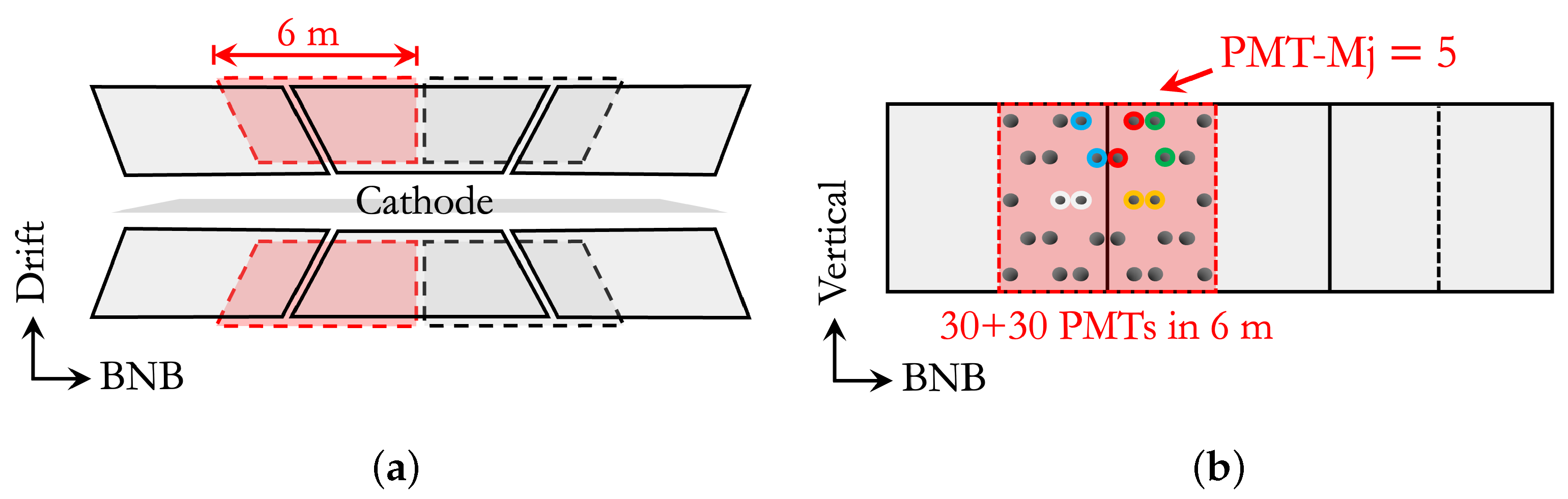
Considering the
energy scale of BNB and NuMI neutrinos, interactions are on average expected to be contained in 4 m longitudinally, motivating a trigger logic based on limited TPC regions. To generate the “PMT-majority” global trigger, at least five LVDS signals are required in a 6 m longitudinal module slice in temporal coincidence with the BNB or NuMI beam gate windows (“majority-5”/“mj-5” setting). Each 6 m window contains 60 PMTs (30 per TPC, front-facing). For the initial Run1, three side-by-side slices were considered. The trigger was then improved in efficiency and uniformity in Run2 by introducing two additional overlapped windows (
Figure 2).
A diagram of the FPGA implementation for the PMT-majority trigger is provided in
Figure 3.
Several triggers are routinely collected with both the BNB and NuMI beams. Triggers with the described PMT-majority logic are collected both “on-beam”, in coincidence with the beam spill extractions, and “off-beam”, where a gate signal is opened between beam spills to collect cosmic ray background statistics. Additionally, “minimum-bias” triggers can be acquired by just requiring that a gate is opened, without any request a priori on the scintillation light in the event. During data taking, minimum-bias triggers are collected every 200 (60) on-beam gates for BNB (NuMI) and every 20 off-beam gates. Minimum-bias data are used for measuring the trigger efficiency, for calibrations, and detector physics studies.
The ICARUS trigger was designed to select physical interactions within the BNB and NuMI beam spills and is observed to reject ≃97% of the spills that are either empty or containing negligible activity.
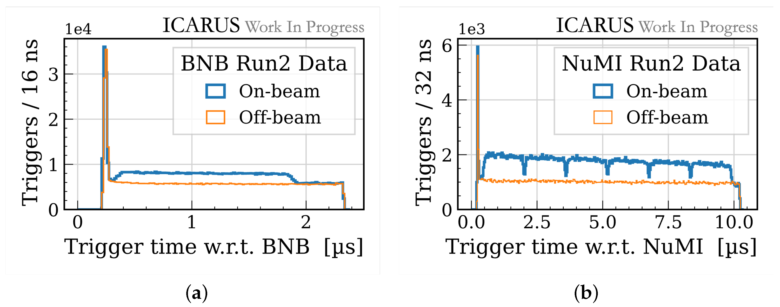
Figure 4 shows the global trigger time with respect to the BNB (left) and NuMI (right) beam gate opening times for Run2 data (≃2 ×
POT for BNB, ≃2.7 ×
POT for NuMI). The beam gate durations are slightly larger than the actual beam spills (respectively, 1.6 µs and 9.6 µs for BNB and NuMI). Beam-related activity (mainly neutrinos in the active volume, but also beam–halo interactions spilling into the detector) produces an evident excess in the on-beam data with respect to the off-beam data. The relative fraction is higher for NuMI, which has higher beam intensity. The coarse NuMI beam structure consisting of 6 batches with ≃100 ns spacing is also observed. The peak in triggers at the gate opening is produced by energetic cosmic rays crossing the detector right before the beam gates, whose late scintillation light is enough to meet the PMT-majority trigger requirements, hence producing a global trigger.
2.1. Performance of the Trigger System
To study the performance of the trigger system, the trigger logic is emulated starting from the recorded PMT waveforms in off-beam minimum-bias data. To avoid biasing the trigger efficiency measurement, timing for cosmic ray particles is provided by the CRT, performing a spatial match between hits on the CRT scintillators and reconstructed tracks in the TPCs.
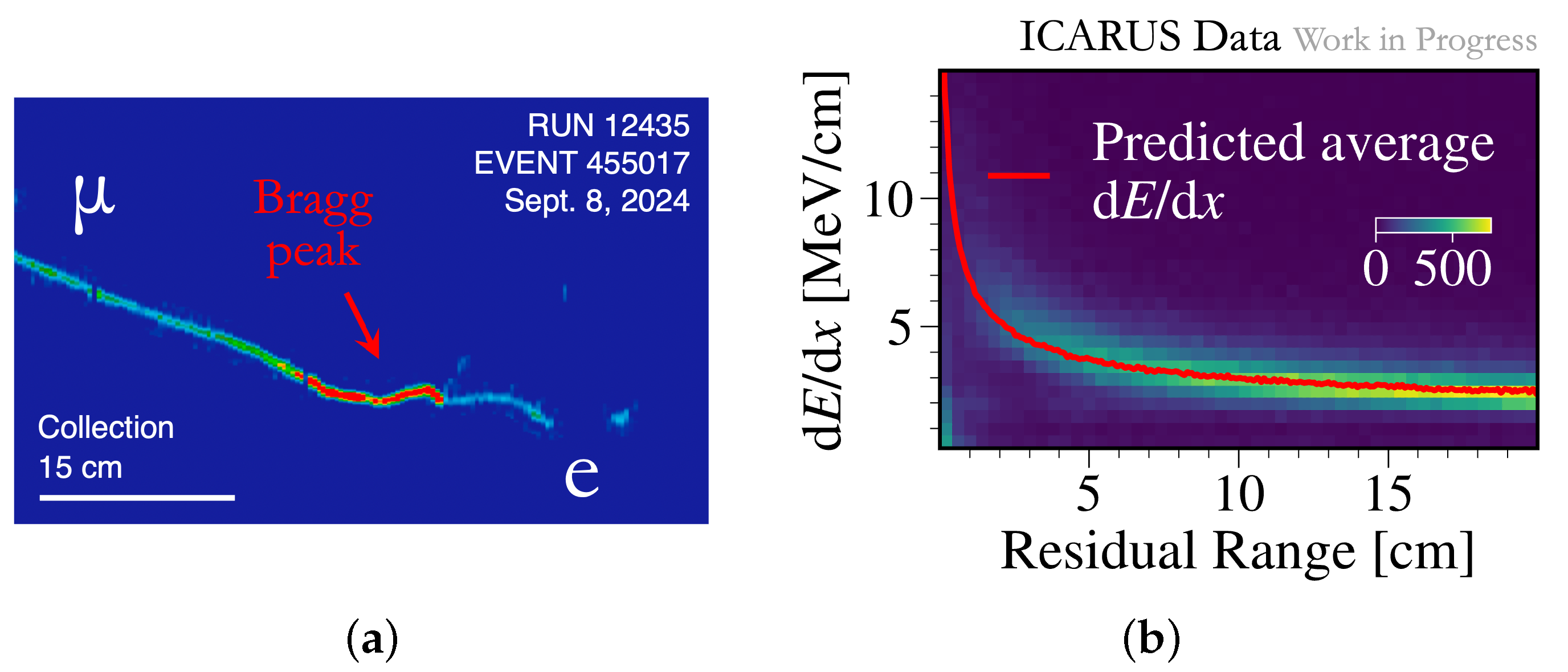
In particular, muons stopping inside the detector are selected (
Figure 5), as they are similar in topology and energy to BNB muon neutrino charged-current interactions, and their energy can be precisely estimated from the residual range. To select the Bragg peak signature of stopping muons, a request is made on the median
local energy deposition at the end of the track to be larger than
. In addition, a calorimetric energy of at least 60 MeV is requested in the last 20 cm, based on the Bethe–Bloch prediction for muons stopping in liquid argon. More information on ICARUS calibrations for precise calorimetry can be found in [
10].
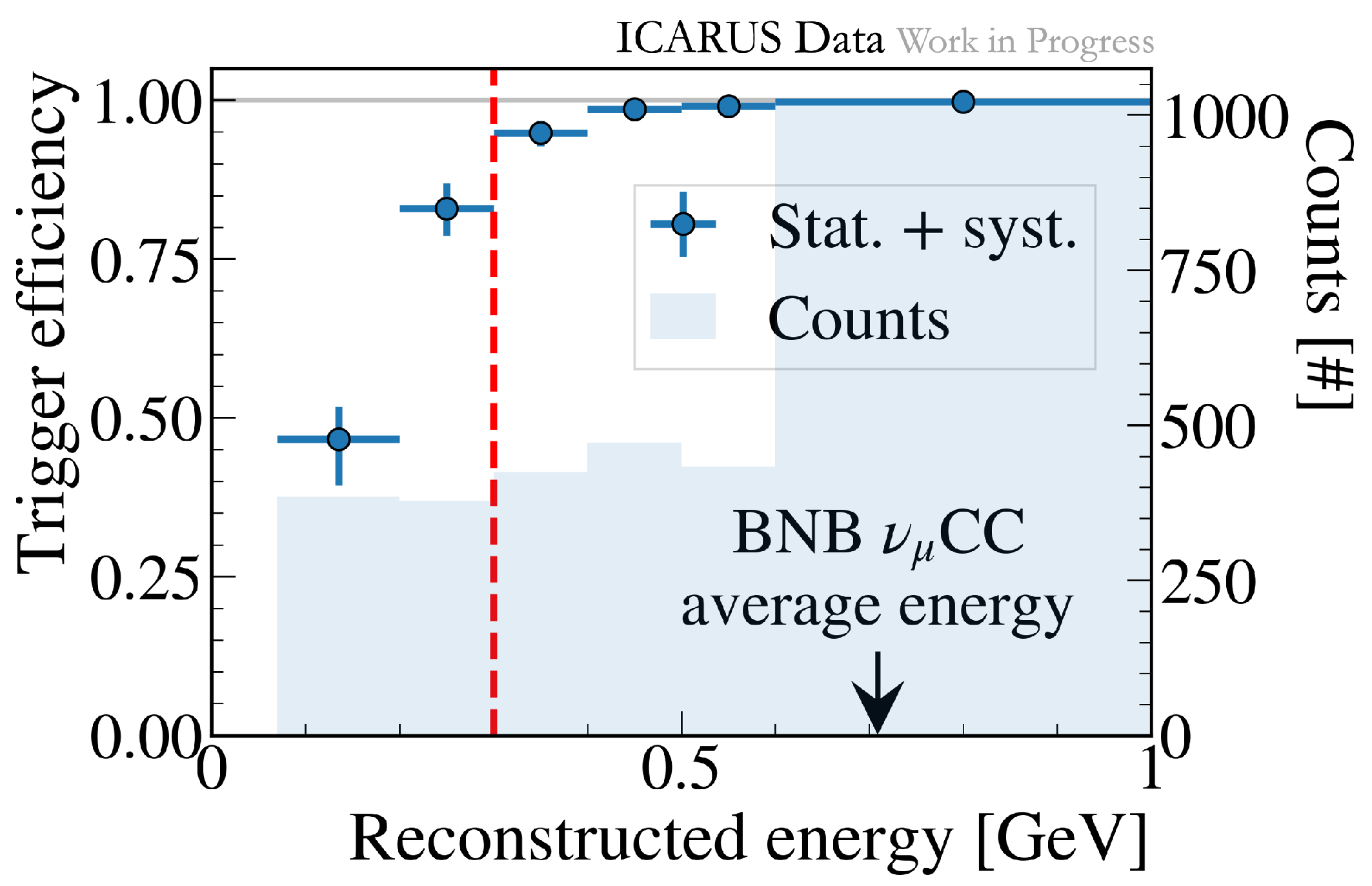
The majority-5 trigger efficiency measurement with stopping muons for Run2 is reported in
Figure 6 as a function of the muon energy estimated from the range (>70 MeV for muons at least 20 cm long). The ICARUS trigger is close to full efficiency above roughly
, with the plateau covering the spectrum of charged-current neutrino interactions from the BNB and the higher-energy NuMI beams. Related systematic uncertainties mainly come from the track reconstruction and selection and from the emulation algorithm, amounting to ≃10% below 200 MeV.
2.2. Cosmic Ray Rejection
ICARUS is operating at the Earth’s surface, facing a challenging ≃11 kHz cosmic ray background while searching for neutrinos from BNB and NuMI.
During the ≃1 ms drift of ionization electrons from beam events, tens of overlapping cosmic ray interactions are acquired. Such cosmic ray particles cross the detector before and after the beam spills, and can be rejected with timing. Scintillation light can provide a prompt signal to determine the time of interactions. Indeed, it would be challenging to acquire several ms of mostly baseline PMT data. To avoid saturating the data acquisition system, additional “out-of-time” triggers are acquired: in Run2, when a mj-9 trigger condition is met in a 2 ms time window around the beam spills, 10 µs of PMT data are read out from the 180 PMTs in the corresponding module.
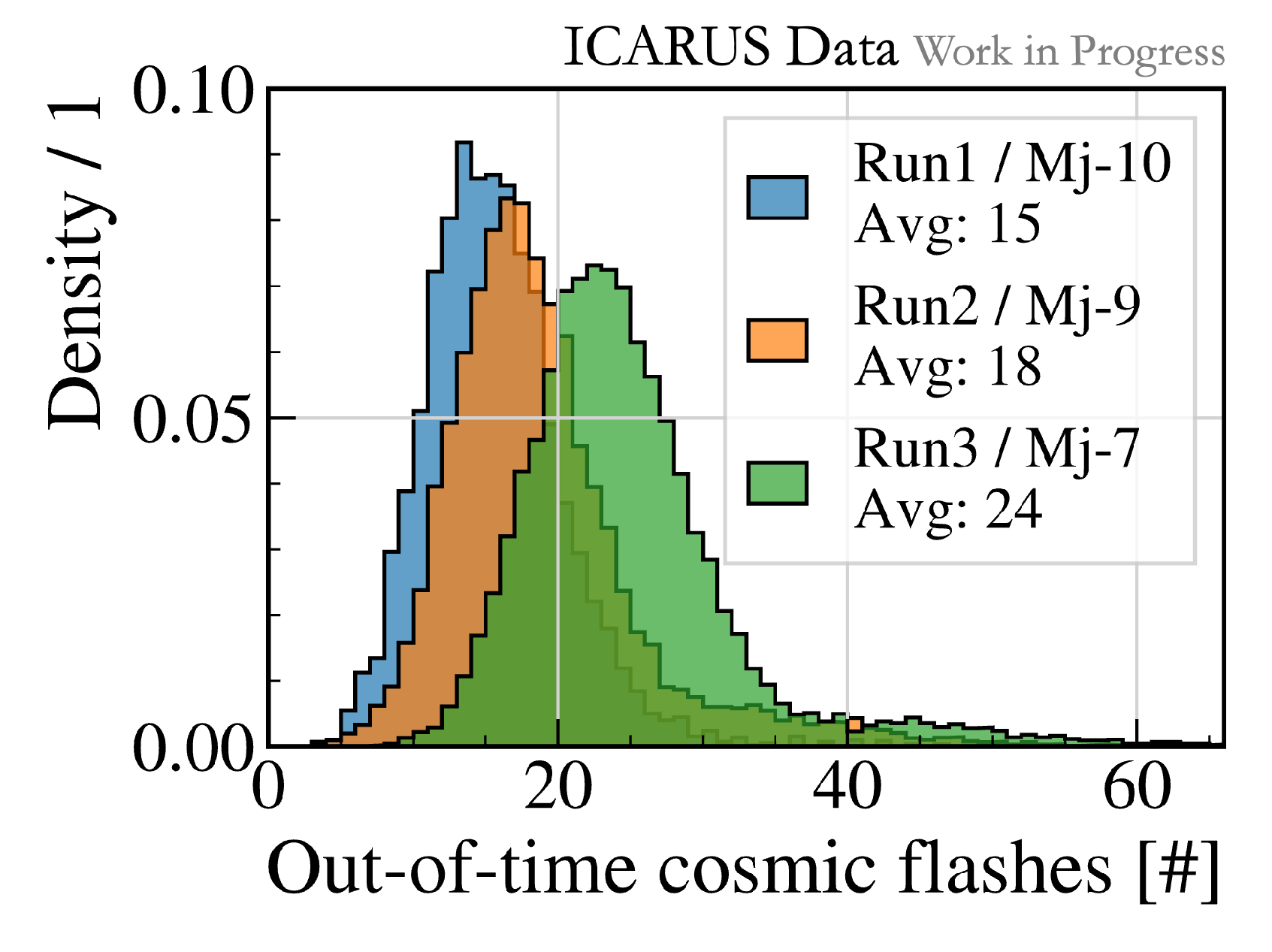
The out-of-time PMT-majority requirement was lowered from mj-10 in Run1, through mj-9 in Run2, down to a mj-7 for the latest Run3 (started in March 2024), hence improving the cosmic background rejection potential.
Figure 7 shows the number of out-of-time reconstructed scintillation light flashes (i.e., clusters of PMTs fired in a module in a 1 µs window) per event in the three ICARUS run configurations.
2.3. Adders
An independent trigger system based on the total amount of scintillation light rather than a multiplicity of fired PMTs is being developed to operate in parallel to the well-established PMT-majority trigger, possibly improving the event recognition efficiency at low energies.
Dedicated custom “adder” boards were developed, receiving signals from 15 PMTs in a 3 m TPC slice (corresponding to the same group of signals going into a digitizer) and splitting them into two 95% and 5% components. While the major signal component proceeds to the corresponding digitizer and is used for the PMT-majority trigger, the 5% components from the 15 PMTs are summed up analogically. The 24 adder signals from the 360 PMTs (12 adder signals per TPC) are proportional to the total deposited light in 3 m TPC slices. Adder signals are discriminated with a 60 mV threshold, chosen as a compromise between noise levels and maintaining sustainable trigger rates.
An adder global trigger is produced by requiring at least one adder signal over the threshold. For Run3, the adder trigger was introduced in logic-OR with the PMT-majority trigger, being able to distinguish between the two trigger sources at the hardware level (
Figure 8). A global trigger rate of ≃0.8 Hz was obtained.
For out-of-time triggers, to avoid overcrowding the DAQ, only the four adders at the southernmost and northernmost corners (with respect to the BNB direction) in each module are considered, where the multiplicity-based logic is more inefficient due to border effects. A cosmic ray rate of ≃11 kHz is measured from the collected light, approaching the physical rate expected at the Earth’s surface.
Adders provide complementary information with respect to the multiplicity-based trigger logic, as interactions close to the PMTs can produce large scintillation light signals triggering PMTs, potentially not meeting the mj-5 requirement.
3. Conclusions
The ICARUS trigger, based on prompt scintillation light signals in liquid argon collected by 360 PMTs, is online and fully implemented on FPGA-based hardware. The main trigger is based on the multiplicty of PMT signals within limited TPC regions in coincidence with the proton extraction signals from the Booster and Main Injector accelerators.
The trigger efficiency, studied with stopping muons from cosmic ray minimum-bas data, is shown to saturate roughly at ∼300 MeV, with the plateau effectively covering the spectrum of BNB and NuMI charged-current interactions.
To improve the event recognition efficiency for low-energy events, a complementary trigger system was developed, based on the total amount of scintillation light rather than a multiplicity. The system, based on custom “adder” boards, was deployed and included with the main PMT-majority trigger for the latest physics runs, where several additional beam-induced interactions were collected.


