


The ATLAS Inner Tracker Strip Detector System for the Phase-II Large Hadron Collider Upgrade †


Abstract
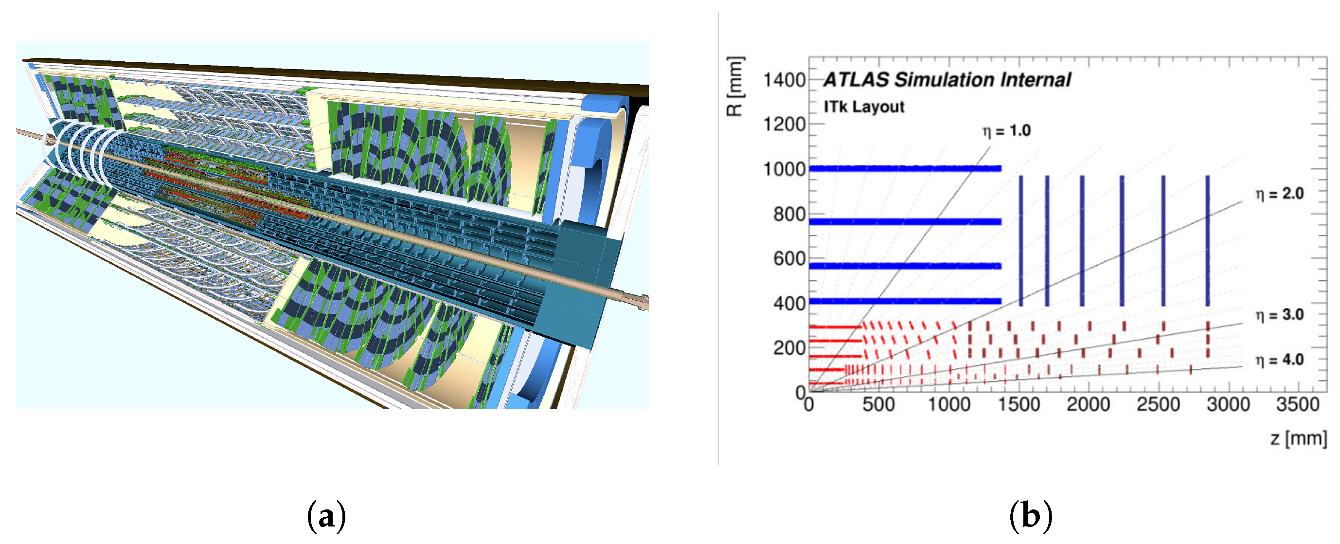
1. High-Luminosity Large Hadron Collider (HL-LHC) and the ATLAS Inner Tracker (ITk)
2. ITk System
2.1. Sensors
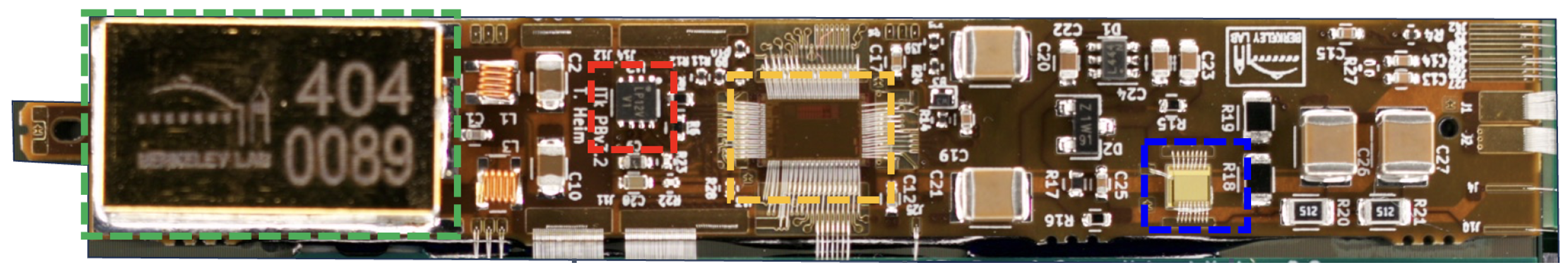
2.2. Power Boards
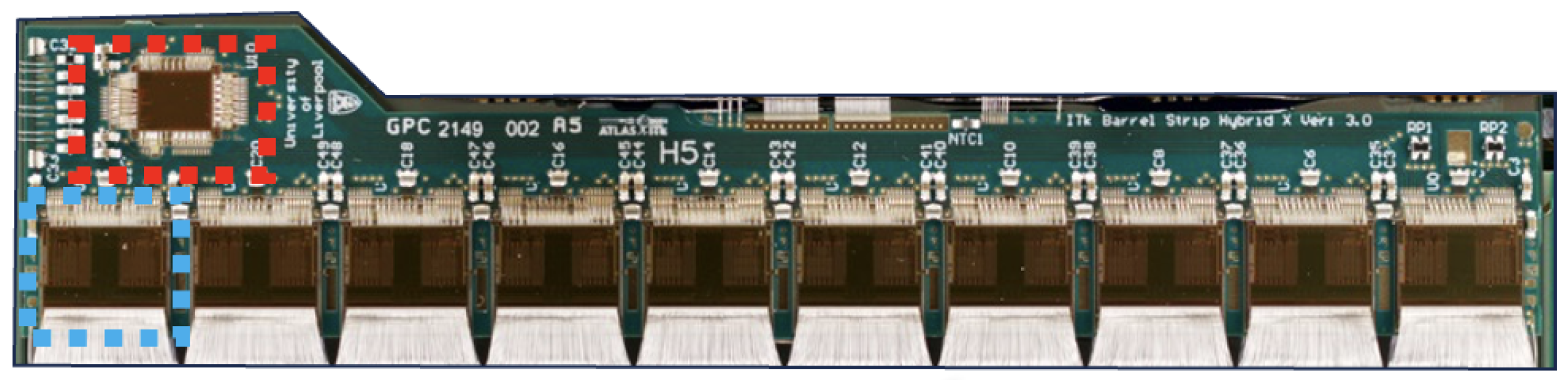
2.3. Hybrids
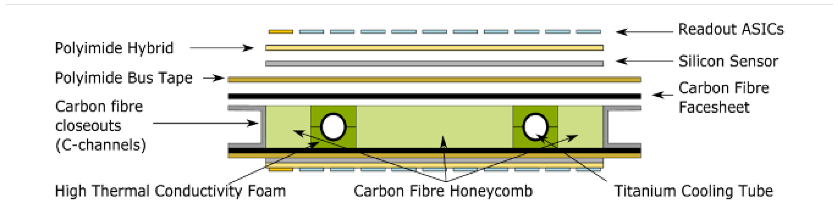
2.4. Modules
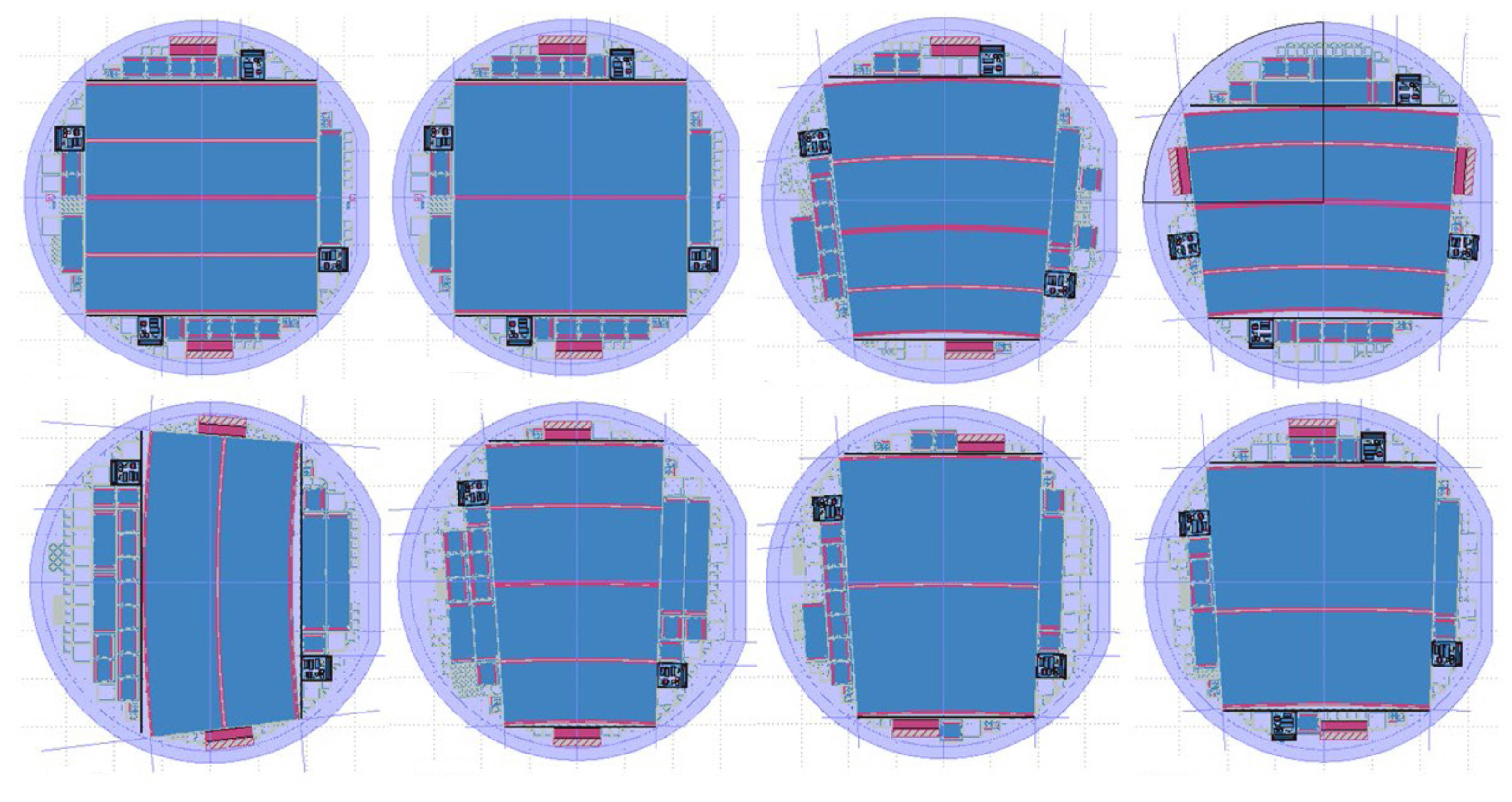
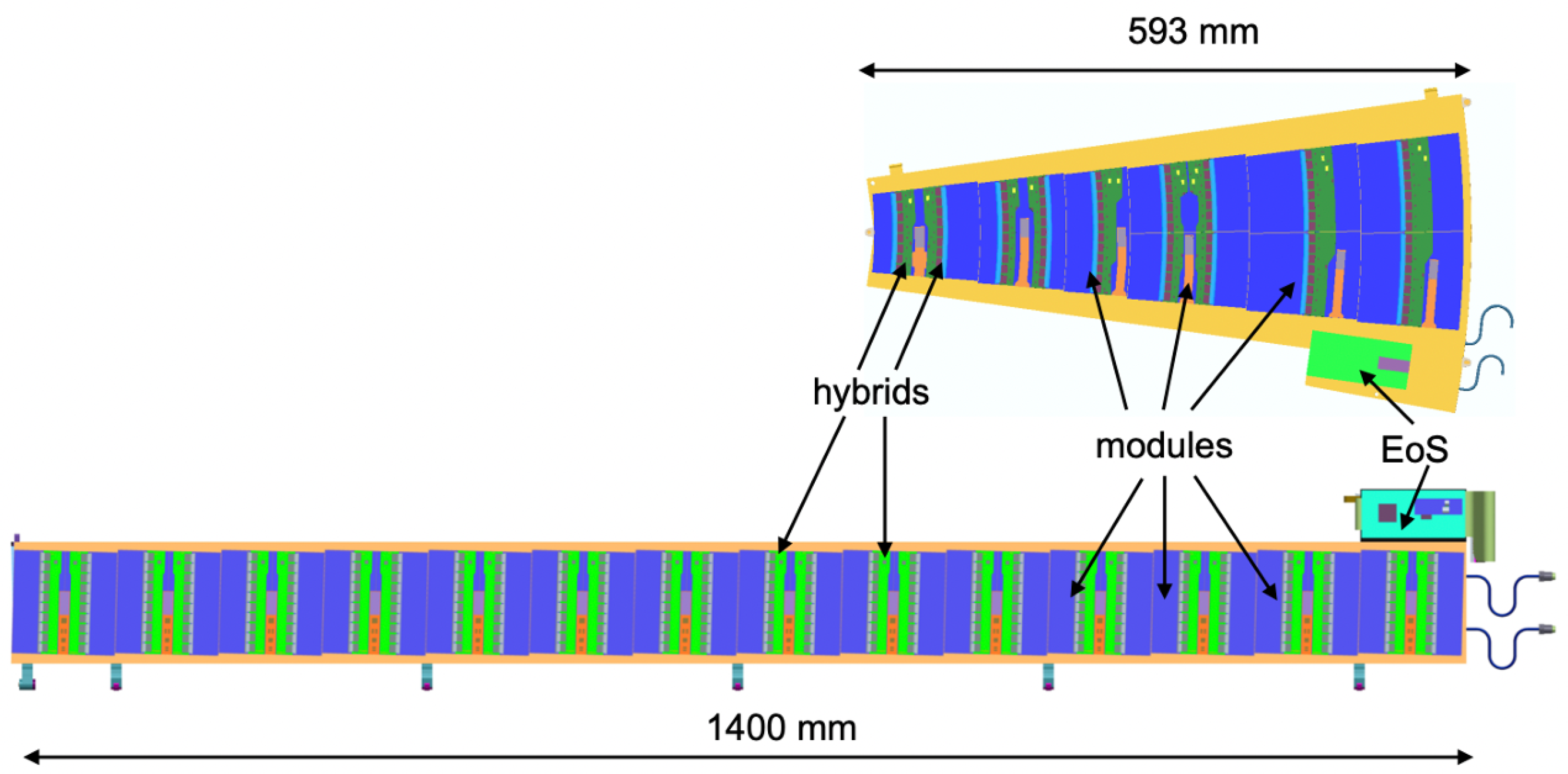
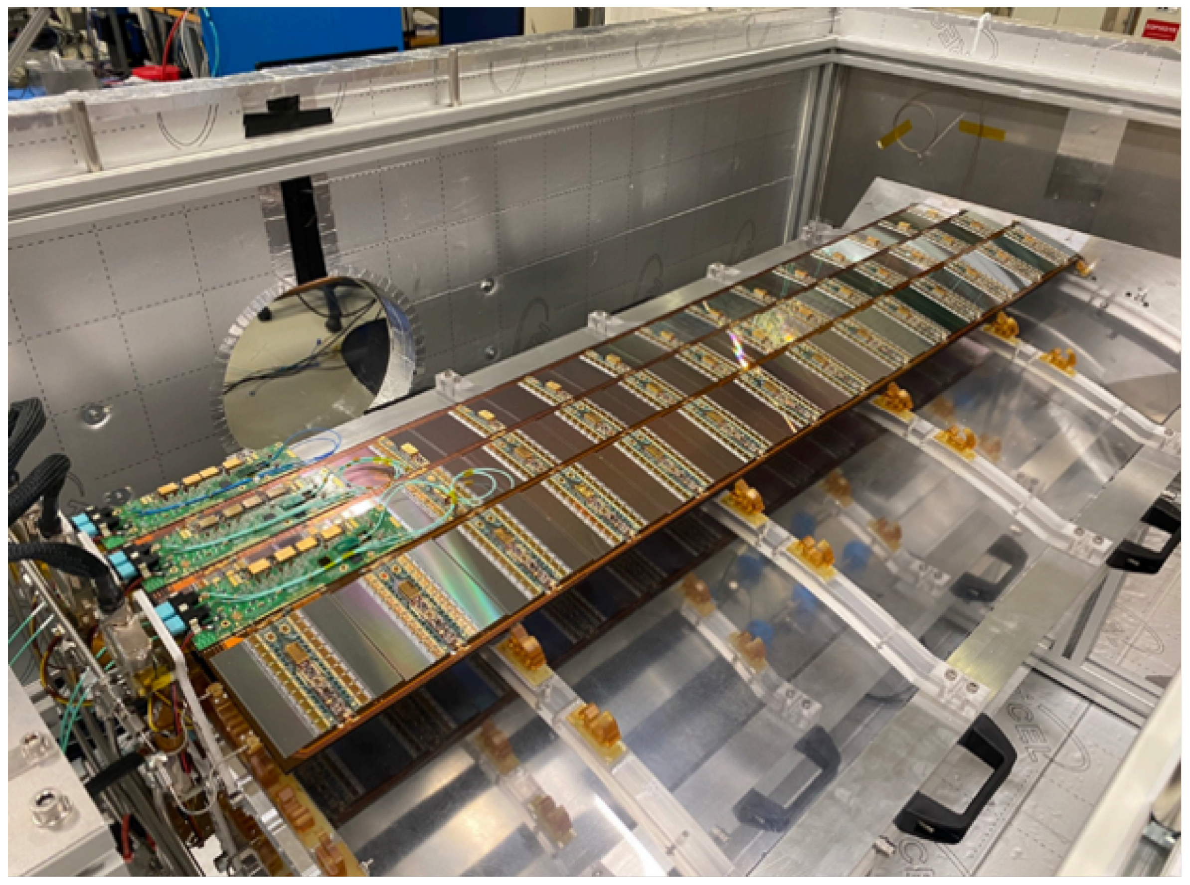
2.5. Local Support Structures
3. Assembly and Testing
3.1. Stave and Petal Loading
3.2. Quality Control
3.3. Systems Tests
3.4. Challenges and Mitigation
4. Conclusions and Outlook
Funding
Data Availability Statement
Conflicts of Interest
References
- The ATLAS Collaboration; Aad, G.; Abat, E.; Abdallah, J.; Abdelalim, A.A.; Abdesselam, A.; Abdinov, O.; Abi, B.A.; Abolins, M.; Abramowicz, H.; et al. The ATLAS Experiment at the CERN Large Hadron Collider. J. Instrum. 2008, 3, S08003. [Google Scholar] [CrossRef]
- ATLAS Collaboration. Technical Design Report for the ATLAS Inner Tracker Strip Detector; Technical report; CERN: Geneva, Switzerland, 2017. [Google Scholar]
- Unno, Y.; Abidi, H.; Affolder, A.; Affolder, K.; Allport, P.P.; Beaupre, S.; Beck, G.A.; Bernabeu, J.; Bevan, A.J.; Chisholm, A.; et al. Specifications and pre-production of n+-in-p large-format strip sensors fabricated in 6-inch silicon wafers, ATLAS18, for the Inner Tracker of the ATLAS Detector for High-Luminosity Large Hadron Collider. J. Instrum. 2023, 18, T03008. [Google Scholar] [CrossRef]
- Miyagawa, P.S.; Affolder, A.; Affolder, K.; Beaupre, S.; Beck, G.A.; Bernabeu, P.; Bevan, A.J.; Chen, Z.; Dawson, I.; Deshmukh, A.; et al. Analysis of the results from Quality Control tests performed on ATLAS18 Strip Sensors during on-going production. Nucl. Instruments Methods Phys. Res. Sect. A Accel. Spectrometers Detect. Assoc. Equip. 2024, 1064, 169457. [Google Scholar] [CrossRef]
- Poley, L.; Sawyer, C.; Addepalli, S.; Affolder, A.A.; Allongue, B.; Allport, P.; Anderssen, E.; Anghinolfi, F.; Arguin, J.F.; Arling, J.H.; et al. The ABC130 barrel module prototyping programme for the ATLAS strip tracker. J. Instrum. 2020, 15, P09004. [Google Scholar] [CrossRef]
- Tishelman-Charny, A. The quality control programme for ITk strip tracker module assembly. J. Instrum. 2024, 19, C03015. [Google Scholar] [CrossRef]
- Dyckes, G.; Kurth, M.K.; on behalf of the ITk Strip collaboration. How the discovery of Cold Noise delayed the production of ATLAS ITk strip tracker modules by a year. J. Instrum. 2024, 19, C04058. [Google Scholar] [CrossRef]
- Iakovidis, G. The ATLAS ITk Strip detector system for the Phase-II LHC upgrade. Nucl. Instruments Methods Phys. Res. Sect. A Accel. Spectrometers Detect. Assoc. Equip. 2024, 1062, 169241. [Google Scholar] [CrossRef]


Disclaimer/Publisher’s Note: The statements, opinions and data contained in all publications are solely those of the individual author(s) and contributor(s) and not of MDPI and/or the editor(s). MDPI and/or the editor(s) disclaim responsibility for any injury to people or property resulting from any ideas, methods, instructions or products referred to in the content. |
© 2025 by the author. Licensee MDPI, Basel, Switzerland. This article is an open access article distributed under the terms and conditions of the Creative Commons Attribution (CC BY) license (https://creativecommons.org/licenses/by/4.0/).
Share and Cite
Duden, E., on behalf of the ATLAS-ITk Strips Collaboration. The ATLAS Inner Tracker Strip Detector System for the Phase-II Large Hadron Collider Upgrade. Particles 2025, 8, 16. https://doi.org/10.3390/particles8010016
Duden E on behalf of the ATLAS-ITk Strips Collaboration. The ATLAS Inner Tracker Strip Detector System for the Phase-II Large Hadron Collider Upgrade. Particles. 2025; 8(1):16. https://doi.org/10.3390/particles8010016
Chicago/Turabian StyleDuden, Emily on behalf of the ATLAS-ITk Strips Collaboration. 2025. "The ATLAS Inner Tracker Strip Detector System for the Phase-II Large Hadron Collider Upgrade" Particles 8, no. 1: 16. https://doi.org/10.3390/particles8010016
APA StyleDuden, E., on behalf of the ATLAS-ITk Strips Collaboration. (2025). The ATLAS Inner Tracker Strip Detector System for the Phase-II Large Hadron Collider Upgrade. Particles, 8(1), 16. https://doi.org/10.3390/particles8010016