Abstract
The report presents the results of using the nonperturbative kinetic approach to describe the excitation of plasma oscillations in a graphene monolayer. As examples the constant electric field as well as an electric field of short high-frequency pulses are considered. The dependence of the induced conduction and polarization currents characteristics on the pulse intensity, pulse duration, and polarization is investigated. The characteristics of secondary electromagnetic radiation resulting from the alternating currents is investigated. The nonlinear response to the external electric field characterizes graphene as an active medium. Qualitative agreement is obtained with the existing experimental result of measurements of currents in constant electric fields and radiation from graphene in the case of excitation by means of the infrared and optical pulses.
PACS:
81.05.Uw; 64.60.Ht; 73.50.Fq
1. Introduction
Graphene is a unique real material, promising for microelectronics and described by a fairly simple quantum field model (massless QED). These features of graphene and the possibility of the experimental verification of the theoretical predictions explain the great interest in theoretical studies in the electrodynamics of graphene. A specifics here is the lack of analyticity in the coupling constant. This makes the use of nonperturbative approaches relevant here.
One of these directions is associated with the adaptation of general methods of QED for strong fields based on exact solutions of the main QED equations for some simple models of the external electric field [1,2,3]. In graphene, this approach allows a detailed study of the electrodynamics in the case of a constant [4] and pulsed (Sauter) electric field [5]. For the case of a constant field, satisfactory agreement with experiment was obtained [6,7,8].
Another recently proposed line of research in graphene is based on the use of methods of nonperturbative kinetic theory, which in the simplest case is valid for spatially homogeneous nonstationary electromagnetic fields. Within the framework of standard QED, such an approach was proposed in several papers [9,10,11,12] and is currently successfully applied in various problems of QED in strong external fields (for example, [13,14]) in describing the vacuum production and evolution of an electron – positron plasma. A promising field of application of this approach is also in QCD, where problems of the creation and evolution of a quark-gluon plasma in the initial stage of the collision of ultrarelativistic heavy ions can be considered (for a review of the early works in this direction, see [15]). This universal approach was recently adapted to the model of single-layer graphene in [16,17,18].
The work consists of two interdependent parts. Section 2, Section 3, Section 4 and Section 5 contain an account of nonperturbative kinetic theory and electrodynamics of graphene based on the quasiparticle representation. On this foundation the analysis of currents and plasma oscillations is performed in Section 6, Section 7 and Section 8 for the cases of a constant and pulsed external fields. These results are compared with the existing experimental data. Finally, some actual perspectives on forthcoming investigations are discussed in Section 9.
2. Statement of the Problem
The aim of this work is the construction and subsequent study of the extended kinetic theory of carriers and radiation in single-layer plane graphene excited by the action of an external semiclassical field . Internal currents in turn generate internal fields . Before making more realistic approximations, the quasiclassical fields are assumed to be spatially homogeneous, arbitrarily depending on time and acting in the graphene plane, so that in the Hamiltonian gauge the structure of the acting field is as follows:
These limitations already mean that the radiation of graphene at the frequencies of plasma oscillations is an isolated problem related to the extension of electrodynamics. Quasiclassical fields can be strong and are nonperturbatively taken into account, while possible quantum fields are described in the framework of the relevant perturbation theory and can be spatially inhomogeneous and leave the limits of the graphene plane. Thus, the effective fields in graphene will be equal
In the nonperturbative part of the problem, the methods and terminology of the kinetic theory based on the quasiparticle representation are used. Supplementing this system with the Maxwell equation for the internal field, we obtain a closed self-consistent system of equations describing at the kinetic level the dynamics of carriers and fields in graphene.
Below we consider the simplest low-energy model of graphene in the presence of an external field (1), which describes the excitations in the vicinity of one of the two Dirac points at the boundaries of the Brillouin zone [19,20,21]. A generalization of the formalism to a tight-binding model can be found in [17].
We write the equation of motion and the Hamiltonian of the basic model in an effective semiclassical field (2)
where is the quasimomentum , are the Pauli matrices,
and m/s is the Fermi velocity. The charge of an electron is . The wave function in (5), (6) is a two-component spinor.
The corresponding current density is equal
3. Transition to the Quasiparticle Representation
Standard quantum field theory is based on the transition to the representation of second quantization in momentum space, which allows for the usual physical interpretation, where the key element is the concept of particles, real or virtual, which are considered as excitations of the physical vacuum. As a result, in the case of free fields, all necessary quantities become state-additive in momentum space with a certain population determined by the statistics of the fields.
The introduction of interaction with an external field violates the additivity of the observables in the Fock space and complicates the interpretation of the formalism in terms of particles and antiparticles.
The transition to the quasiparticle representation [9] to a certain extent allows us to solve this problem and restore clarity in the description of processes in strong fields.
In graphene, the entire scheme for constructing the kinetic theory of vacuum particle production in the standard QED in the quasiparticle representation is preserved, but it is much simplified when constructing the dynamics when implementing the canonical Bogolyubov transformation. The reason for the simplification is the absence of a mass and the reduction in the number of spatial dimensions. This leads to the fact that the spin degrees of freedom are hidden and degenerate. Their existence is reflected only in the flavor number . The inclusion of real spin degrees of freedom requires a generalization of the theory.
The transition to the quasiparticle representation in graphene was used, for example, in [5,16,17,22]. Below we follow the works [5,16,17].
We suppose that graphene is located in a region bounded by a square with side L and go to the momentum representation,
In this representation, we write the basic Hamiltonian (4)
where is the quasi-momentum, and the equation of motion (3) is
The diagonalization of the Hamiltonian (8) can be done explicitly using the unitary transformation with the matrix [22]
The parameter is fixed here by the equality
where is the quasienergy
According to the selected low-energy model, the dispersion law (12) is valid in the vicinity of the Dirac point at the boundaries of the Brillouin zone.
The equation of motion in the quasiparticle representation will have the form
where the function
describes the transition between states with positive and negative energies and can be found from the equality
In the Formula (14) is the electric field strength.
If we now write the spinor taking into account expansion (7) in the form
then the Hamiltonian of the system in the new representation will be equal to:
We now turn to the representation of occupation numbers and define the creation and annihilation operators of electrons and holes over the instantaneous vacuum state , demanding for these operators the standard anticommutation relations,
The remaining elementary anticommutators are equal to zero.
The equations of motion (13) can be written using (16) in terms of amplitudes
or in the form of Heisenberg-type equations with respect to the operator
where
is the Hamiltonian of the fermion subsystem, including the Hamiltonian (17) and the Hamiltonian
describing the effects of vacuum polarization under the influence of the field.
4. Basic Kinetic Equation
Below, in the quasiparticle representation, under kinetic equation (KE) will be understood the closed integro-differential equations for the distribution functions of electrons and holes
Subsequently, these functions are considered equal,
by virtue of the assumption of electroneutrality of the system at each moment of time. The averaging in (25), (26) is performed over the in-vacuum state.
To get a closed system of KE, we differentiate with respect to time and use the equations of motion (21)
where anomalous averages are introduced by
Differentiating them in time, we obtain
As a result of the integration of these equations over time and substitution in (28), we obtain the desired KE of non-Markovian type
where the dynamic phase is introduced by
The Equation (33) should be supplemented with an initial condition compatible with the requirement of electroneutrality (27). The simplest option corresponds to the absence of excitations at the initial moment of time .
For the first time, KE of this type were obtained in independent works [9,10,11] in the framework of standard QED. The specifics of the quantum field system under consideration consists in the ability to perform canonical Bogolyubov transformations in an explicit form (Section 3). Note that the KE (33) is valid in the case of an arbitrary polarization of the external field (1). The integro-differential KE (33) can be written in the form of an equivalent system of ordinary differential equations
with appropriate initial conditions
5. Macroscopic Averages
Since, due to the uncertainty relation, the description of the system in terms of time-dependent quasienergy (12) is conditional and acquires physical meaning only in the asymptotic region , the distribution function itself is rather conventional. This feature of the quasiparticle approach was noted in the literature (for example, [23]). On the other hand, it is understood that under certain conditions (for example, in the case of systems located in a limited region of space, ), the evolution of a macroscopic quantum field system in time-dependent external conditions can be controlled at any time in various ways (using radiation into the external region or various responses to weak external probes). Such, for example, are experiments on graphene samples in the optical excitation range [24,25] or planned experiments to detect an plasma in the focal spot of computer-propagating powerful laser beams [26,27,28].
In such a situation, macroscopic averages obtained by taking the expectation value with states and integrating the dynamic characteristics of quasiparticles over the momentum space, statistically weighted with the distribution function playing the role of time-dependent functions mediating between the dynamic characteristics of quasiparticles and physical observables.
The density of excited electron-hole () pairs is the simplest quantity of this type.
where is the total number of flavors in the model under consideration.
From the full Hamiltonian of the fermionic subsystem (23) follows the expression for the total energy density of the electron - hole subsystem, which consists of the sum of the quasiparticle and polarization parts
where
where is the vacuum polarization function (37).
The current density can also be represented as the sum of the conduction and polarization currents
where
To write these currents in terms of the functions , we use the Formula (6) and perform a unitary transition to the quasiparticle representation there (Section 3),
Using formulas (10), (16) and the definition (37) here, we obtain the expression for the conduction current density as a result
where
is the propagation velocity of the quasiparticle excitation. In the derivation of Formula (46), the vacuum unit was omitted . The polarization current density is
where the vector of “conjugate velocity” is determined through the components of the vector
Using this definition, one can write the amplitude (14) in the following form:
Thus, the functions and determine the energy and current due to the polarization of the medium. We now obtain the law of conservation of energy in the quasiparticle subsystem. Differentiating in time the density of quasiparticle energy (41) and using the Formulas (46)–(49) for the current density and relation (50), we obtain
where is the total current density (43). This relation allows a different formulation. We write the Maxwell equation for the internal plasma field
and write in Equation (51) the total electric field as a sum
As a result, we obtain
Similarly, relation (42) implies the relation describing the energy balance of vacuum polarization
6. Constant Field
We begin the demonstration of the opportunities of the developed approach with the case of a constant external electric field:
Constant is both the absolute value of the field strength and its direction. Further, the first axis of the used two-dimensional coordinate system is associated with this direction. In this case, it is convenient to compare with the results of using the Landauer approximation (or the Landauer-Datta-Lundstrom (LDL) model) [29,30,31] for calculating the characteristics of the current arising in graphene samples with the results of the presented approach. Some nontriviality is that quite different methods and different spaces of description are used here: the considered kinetic approach is formulated in the t-representation, while the LDL method based on the WKB approximation uses the x-representation. Both approaches are equivalent in the case of a constant electric field.
A constant field does not have any characteristic time scales. Those can only be sought in the characteristics of the material itself or of the simulated sample. For a material (graphene), the natural unit of the time scale is the ratio of the lattice constant to the Fermi velocity s. It makes no sense to consider processes on a smaller time scale. The upper boundary of the time scale is determined by the condition of applicability of the assumption of spatial homogeneity of the system. It depends on the characteristic size of the sample and can be determined by the ratio .
The system of Equation (35) allows only a numerical investigation. For each point of the momentum space , it is solved independently. The region in which the distribution function is localized and the required density of its coverage by the computational grid at the nodes of which solutions for (35) will be sought is determined by the necessary accuracy in calculating the integral characteristics. This is realized by a sequential iterative procedure with stepwise control of the accuracy of the results obtained.
Figure 1 shows the form of the distribution function for two consecutive points of time at a field strength of V/m. The “natural” value is used hereinafter as a unit value for the . Such kind of accumulative behavior of the distribution function is in agreement with the results of [32,33]. The latter work based on the Greens function method takes into account the dissipative mechanism of inelastic scattering of optical phonons.

Figure 1.
The distribution function in the momentum space for two consecutive points of time at the field strength V/m. Left panel: s, Right panel: s.
The distribution function of the excitation on the initial stage is formed and reaches the maximum value very rapidly. Figure 2, left panel, shows the transversal sections of this distribution for different values at early time of the evolution, corresponding to the right edges of the distribution functions in Figure 1. In the case of the ballistic regime the following accumulation of population is a result of the increase of the longitudinal momentum in the direction of the acting electric field at invariable Gauss-like distribution on the transversal momentum . The halfwidth of the -distribution is defined by the field strength E (Figure 2). As a result, the number density of carriers grows proportionally to the action time T of the field, , as in the case of standard QED (see, e.g., [9]).
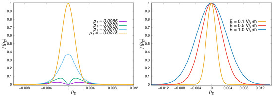
Figure 2.
Left panel: The section of the distribution function for several values of at the field strength V/m; Right panel: The shape of the section for for different field strength E.
In the LDL approach, the problem of calculating the current density through the sample of a material of finite width nm limited by two parallel electrodes is solved by calculating the transmission probability in the presence of a given potential difference (for dispersion of graphene ) [6]:
Therefore, the momentum component does not change its value during tunneling. In spite of the fact that graphene is a gapless semiconductor, the presence of finite conserved values leads to the appearance of an energy gap with the width . In the considered case of a vacuum the initial state temperature and chemical potential are equal to zero, the Fermi energy and there are no free carriers in the interelectrode space. Under these conditions the process of carrier transmission can proceed only by Zener-Klein tunneling. The probability of this tunneling in the WKB approximation is (taking into account the relationship of and ):
First of all, let us note that the distribution (58) of carriers over the transverse momentum reproduces the result (Figure 2, right panel) obtained in the kinetic approach to the permille accuracy, i.e., within the thickness the lines.
The basic problem is that the conduction current density (46) in the absence of dissipation and spatial boundaries depends on the time after switching on the field and increases continuously, which, obviously, is not observed in the experiment, where each value of the potential difference corresponds to its steady-state current density. So, under the conditions of the real experiment [6] it is necessary to take into account the presence of the electrodes, which limit the lifetime of the carriers. From this point of view the process of carrier generation must permanently continue throughout the entire measurement process and be uniform in the area of the sample. Knowing the strong anisotropy of the carrier spectrum, it is possible to assume in the first approximation that all of them move towards the electrode of the corresponding polarity with the velocity . In this case, the average lifetime of carriers is for m. At the end of this time after switching on the field, the rate of generation of carriers becomes equal to the rate of their escape through the electrodes. The steady-state current values will be constant and can be calculated in both approaches (Table 1).

Table 1.
Comparison of calculated current density values for a sample with m in the range of potential differences from V to V.
The results of these calculations coincide with high degree of accuracy in the considered range of parameters. Indirectly this shows a good coincidence with experiment [6]. The given list of values strictly corresponds to the law . This dependence is corroborated by other sources [4,5].
The kinetic method presented here can be a valid outside the framework of the applicability of the WKB approach, for example, in alternating electric fields in the region of sufficiently high frequencies. An indirect confirmation of this is the difference in the results for a thinner (tenfold) sample with a correspondingly shorter carrier lifetime (Figure 3). In this case the difference reaches almost . Both, the kinetic and the WKB approach, predict superlinear growth of the current density with almost coinciding exponents .

Figure 3.
Comparison of calculated conduction current density for a sample with nm in the range of electrical field strengths E from 0.1 V/m to 1.0 V/m (potential differences from 0.01 V to 0.1 V).
Above, we limited ourselves to considering only the conduction current in the situation of a stationary process, when the number of carriers born compensates for their departure from the sample. In the kinetic approach, the behavior of the conduction current (46) and the polarization current (48) can be reproduced at times , when carrier losses at the sample boundaries can be neglected. The change in the surface density of the conduction current, polarization current and their sum after turning on the constant field of V/m directed along the x-axis is shown in Figure 4.

Figure 4.
Conduction current (upper curve), polarization current (bottom curve) and their sum as a function of time for .
The behavior of the polarization current is fundamentally different from conduction current behavior and has the form of damped oscillations asymptotically reaching a constant negative value. Nevertheless, the contribution of the conduction current becomes dominant quite quickly.
7. Short High Frequency Pulses
Next, we consider the field model of pulses with a cyclic carrier frequency and a Gaussian envelope with duration parameter ,
The phase shift sets the position of the absolute maximum of the field relative to the maximum value of the envelope (which will be associated with the time ). The spatial direction of the field is constant. Below we stay within the limitations of the low-energy model and consider the region of rather small field strengths and frequencies. In the case of strong fields it is necessary to use some generalizations of this model. For example, a corresponding generalization of the kinetic theory was developed in the work [17] for the tight binding model of the nearest neighbour interaction [21,34,35].
We choose the characteristics of the field so that they correspond to the parameters of the experiments described in [36]. These are very short pulses with THz carrier frequency and duration parameter s, which almost coincides with the constant-field action time considered above. But since in this case the field turns on and off relatively slowly, to accurately reproduce the behavior of the model, we will consider a several times longer interval. The electric field amplitude is V/m, which is an order of magnitude greater than that considered above for a constant field. To accurately reproduce the parameters, we used a nonzero value of the carrier phase shift . An explicit form of the dependence of the field on time is shown in Figure 5. The field is formed by a linearly polarized electromagnetic wave and is assumed to be directed along the x-axis.
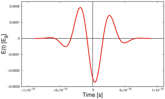
Figure 5.
Time dependence of the field strength for the Gaussian envelope harmonic pulse (60) for V/m, THz, and s.
The field strengths are expressed as , where V/m.
The distribution function formed under the action of such a field through s after passing the maximum (maximum envelope, since in this case ), is presented in the following Figure 6.
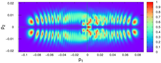
The distribution function is localized in the vicinity of the Dirac point. The distribution of populated states is much more complicated than in the case of a constant field. Thus reproduction of integral characteristics in this case may be more time consuming. The figure is based on the results of solving kinetic equations on a maximally simplified grid. The carrier density (39) evolution reproduced from these data for a time interval from s to s is shown in the following Figure 7.
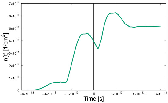
Figure 7.
The carrier density evolution for the field of Figure 5 for a time interval from s to s.
Starting from zero, the carrier density is quite difficult to evolve and reaches a final constant value, which is the residual carrier density. A short field pulse generates several carriers, which, in the absence of dissipation, continue to exist even after the field is turned off.
We consider one more variant of a field of the form (60). This will be a relatively long infrared pulse, similar in parameters to those considered in [25]. We define its cyclic frequency as THz, which corresponds to a wavelength of m and a photon energy of eV. The duration parameter is s. The phase shift was chosen equal to zero. The maximum electric field strength was determined based on the declared energy flux density in the focal spot of 7 GW/cm and reaches ≈2.2 V/m and exceeds by almost two orders of magnitude the corresponding value from the previous example. The impulse with these characteristics has the form shown in Figure 8.

Figure 8.
Time dependence of the field strength for the Gaussian envelope harmonic pulse (60) for V/m, THz, and s.
The form of the distribution function at the final stage of the action of the external field is shown in Figure 9.
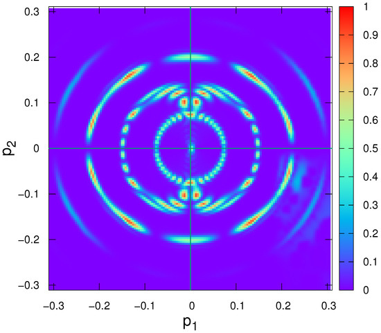
Figure 9.
Momentum space distribution function at the final stage of the action of the external field.
The region in which non-zero values of the distribution function are observed in this case is approximately . The distribution of occupied states has a characteristic ring structure. Due to the great computational complexity in this case, the results are presented for a grid. It allows getting a general idea about the structure of the distribution function. The evolution of the carrier density is shown in Figure 10:
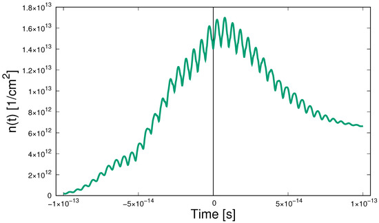
Figure 10.
Time dependence of the carrier density for the infrared pulse of Figure 8.
At the stage of increasing field amplitude, an increase in the density of carriers with small oscillations is observed. At the stage of turning off the field, a drop to a certain residual value takes place.
Conduction and polarization currents for a pulsed alternating field with a cyclic frequency THz (Figure 5) are shown in Figure 11.
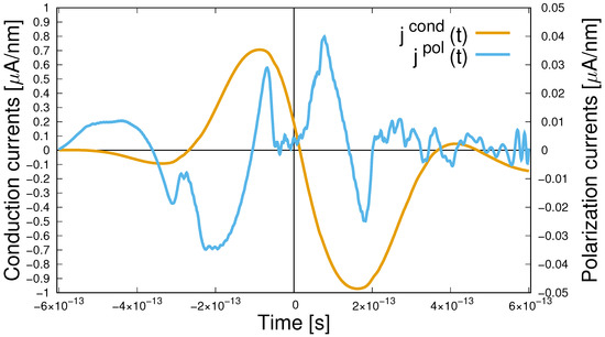
Figure 11.
Time dependence of the conduction and polarization currents for a pulsed alternating field with a cyclic frequency THz.
For the conduction current, one can note some qualitative analogy with the time dependence of the acting field.The nature of the dependence on the time of the polarization current is more complicated.
For an infrared pulse, the dependence of currents on time are shown in Figure 12.

Figure 12.
Time dependence of the conduction and polarization currents for a pulsed alternating field with a cyclic frequency THz.
The conduction current demonstrates a very good reproduction of the general nature of the acting field: it is alternating, the period of polarity change obviously coincides with the period of the carrier of the simulated pulse. The amplitude of the conduction current increases and decreases along with an increase and decrease in the amplitude of the acting field. Obviously, there is a phase shift between it and the external field, because at the time , when the field reaches its maximum value (and this is the absolute maximum), the conductivity current is close to zero. The behavior of the polarization current is fundamentally more complex. Over the entire time interval presented, in which the conduction current has time to increase by several of orders of magnitude and then also to decrease its amplitude, the polarization current does not show obvious signs of a regular change in its amplitude, but only irregular changes in the current value. In the initial section of the time interval presented, one can try to associate its behavior with the current values of the external field, but then a complex interference pattern is observed, which is characteristic for superposition of oscillations with different frequencies. We can draw an analogy with the slow relaxation of the polarization current already after the completion of the action of a short unipolar pulse, which was noted in [37].
8. Plasma Field
The appearance of currents, by virtue of Maxwell’s Equation (52), leads to the generation of a plasma field, which will add to the external field and in the general case will affect the process of further evolution of the system. We use the well-known solution to the problem of the field of a time-dependent current on an infinite plane (see, for example, Ref. [38]):
Here is the magnetic susceptibility of vacuum, c is the speed of light and z is the distance of the observation point from the graphene plane. It follows from this expression that in the case under consideration, the plasma field is determined by the current density. From the expression (61) it follows that the alternating current will generate radiation that carries information about its characteristics. When considering a real sample with a characteristic finite size L, all of the above will be true only for a distance z from its surface that satisfies the condition .
One of the reasons for the continued interest in graphene is the observation of a nonlinear response in it under the action of pulsed fields of the form (61) [25,36]. Does the presented model based on the quantum kinetic equation reflect these properties of graphene? To answer this question, we study the spectral composition of internal currents shown in Figure 11 and Figure 12.
As a tool for studying time series, we use the discrete Fourier transform. The figures (periodograms) below show the squares of the moduli of the coefficients of such a transformation and reflect the contributions of various frequencies to the total field energy. The horizontal axis of the frequencies is calibrated in , the vertical axis has a logarithmic scale. Since the absolute values of the periodogram depend, inter alia, on the length of the sample that we have, only relative values within one periodogram have a well-defined meaning. The spectrum of the acting field plays the role of a reference point.
However, in order to have an initial reference point, we first present in Figure 13 the result obtained from several discrete values of the external electric field shown in Figure 5.
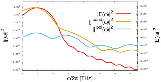
Since the pulse is very short, its spectrum is greatly broadened. Nevertheless, the maximum for the value of 2 THz is quite visible, and outside it there is a smooth and fairly monotonic decrease in the intensity of the spectral components. From this background we show the results of exactly the same processing of a sequence of conduction and polarization currents. The behavior of the spectrum of the conduction current is similar to the behavior of the spectrum of the acting field. However, the curve for the polarization current clearly contains local maxima for frequencies of 2, 6, 10, and 14 THz, which should be interpreted as the appearance of odd harmonics in the spectrum of the internal field with multiplicities of 3, 5, and 7 with respect to the fundamental frequency. If at the fundamental frequency the contribution to the field energy from the polarization current is about three orders of magnitude less then from the conduction current, at the third harmonic they are comparable, and at the fifth and seventh contributions of the polarization current are almost an order of magnitude larger.
Let us now see how this looks in the case of a longer pulse, as depicted in Figure 8. The spectrum of the latter is more localized. The spectrum of the pulse itself is shown in Figure 14. The carrier frequency in this case is THz. Periodograms for currents are also shown in this figure. In this case, the spectrum of both currents clearly shows the odd harmonics with numbers In the above figure, the upper frequency limit is 1000 THz, but if we raise it, we will see harmonics of a higher order. At the carrier frequency, the contribution of the conduction current also dominates. However, already at the next, third, the contribution of the polarization current is about one and a half orders of magnitude greater. With increasing frequency, the contributions of the conduction and polarization currents become almost the same. The appearance of odd harmonics was confirmed in experiments [25,36].
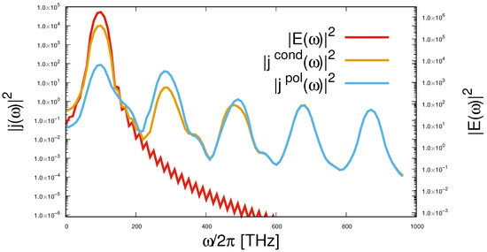
The obtained results are in qualitative agreement with the existing experimental data, so that the suggested kinetic theory is surely verified.
9. Conclusions
In this work, we considered the application of the nonperturbative kinetic equation approach to describe the excitation of plasma oscillations in a graphene monolayer. As examples the constant electric field as well as an electric field of short high-frequency pulses were considered. The dependence of the induced conduction and polarization current characteristics on the pulse intensity, pulse duration, and polarization were investigated numerically for these examples. The characteristics of secondary electromagnetic radiation resulting from the alternating currents was studied and a nonlinear response to the external electric field was found which characterizes graphene as an active medium.
A perspective direction of development of the kinetic theory of graphene is a generalization to the case of additionally accounting for the interaction with the quantized electromagnetic field. One can proceed from the analogy with the works [39,40], where such a generalization was performed in the standard QED on the basis of the Bogolyubov-Born-Green-Kirkwood-Yvon chain of equations in the single photon approximation. Preliminary investigations of radiation on this basis met large difficulties [41]. Analogous research in graphene would allow comparing the quasiclassical radiation (Section 8) with the quantum one and to understand deeper the situation in standard QED. Considerable interest represents a study of cascade processes in graphene (e.g., [42,43] in standard QED) and also of spin phenomena.
Author Contributions
Conceptualization, S.A.S. and D.B.B.; methodology, S.A.S.; software, A.D.P.; validation, A.D.P., D.B.B. and N.T.G.; formal analysis, S.A.S.; investigation, A.D.P. and N.T.G.; data curation, A.D.P.; writing—original draft preparation, S.A.S.; writing—review and editing, D.B.B. and N.T.G.; visualization, A.D.P. and N.T.G.; supervision, S.A.S.; project administration, D.B.B.; funding acquisition, S.A.S. and D.B.B. All authors have read and agreed to the published version of the manuscript.
Funding
S.A.S. thanks for support Russian Science Foundation (Grant No. 19-12-00042). S.A.S. is grateful for support from the joint funding of Helmholtz Centres and JINR Dubna for his participation as a lecturer at the Helmholtz International Summer School in Dubna, July 2019, where the material of this article was presented.
Acknowledgments
We acknowledge B. Dora and R. Moessner for their stimulating interest in our work and for pointing out Ref. [6] to us. D.B. and N.G. are grateful to H.A. Sarkisyan for discussions about physics of low-dimensional systems.
Conflicts of Interest
The authors declare no conflict of interest.
References
- Ritus, V.I. Quantum effects of the interaction of elementary particles with an intense electromagnetic field. In Proceedings of the P.N. Lebedev Physical Institute of the Russian Academy of Sciences; Nauka: Moscow, Russia, 1979; Volume 111, pp. 5–151. [Google Scholar]
- Nikishov, A.I. Problems of the external field in Quantum Electrodynamics. Quantum electrodynamics phenomena in an intense field. In Proceedings of the P.N. Lebedev Physical Institute of the Russian Academy of Sciences; Nauka: Moscow, Russia, 1979; Volume 111, pp. 152–271. [Google Scholar]
- Fradkin, E.S.; Gitman, D.M.; Shvartsman, S.M. Quantum Electrodynamics with Unstable Vacuum; Springer Series in Nuclear and Particle Physics; Springer: Berlin, Germany, 1991; 288p. [Google Scholar]
- Gavrilov, S.P.; Gitman, D.M.; Yokomizo, N. Dirac fermions in strong electric field and quantum transport in graphene. Phys. Rev. D 2012, 86, 125022. [Google Scholar] [CrossRef]
- Klimchitskaya, G.L.; Mostepanenko, V.M. Creation of quasiparticles in graphene by a time-dependent electric field. Phys. Rev. D 2013, 87, 125011. [Google Scholar] [CrossRef]
- Vandecasteele, N.; Barreiro, A.; Lazzeri, M.; Bachtold, A.; Mauri, F. Current-voltage characteristics of graphene devices: Interplay between Zener-Klein tunneling and defects. Phys. Rev. B 2010, 82, 045416. [Google Scholar] [CrossRef]
- Kané, G.; Lazzeri, M.; Mauri, F. High-field transport in graphene: The impact of Zener tunneling. J. Phys. Condens. Matter. 2015, 27, 164205. [Google Scholar] [CrossRef] [PubMed]
- Panferov, A.; Smolyansky, S.; Blaschke, D.; Gevorgyan, N. Comparing two different descriptions of the I-V characteristic of graphene: Theory and experiment. EPJ Web Conf. 2019, 204, 06008. [Google Scholar] [CrossRef]
- Grib, A.A.; Mamaev, S.G.; Mostepanenko, V.M. Vacuum Quantum Effects in Strong External Fields; Friedmann Laboratory Publishing: St. Petersburg, Russia, 1994. [Google Scholar]
- Bialynicky-Birula, I.; Gornicki, P.; Rafelski, J. Phase space structure of the Dirac vacuum. Phys. Rev. D 1991, 44, 1825–1835. [Google Scholar] [CrossRef] [PubMed]
- Schmidt, S.M.; Blaschke, D.; Röpke, G.; Smolyansky, S.A.; Prozorkevich, A.V.; Toneev, V.D. A Quantum kinetic equation for particle production in the Schwinger mechanism. Int. J. Mod. Phys. E 1998, 7, 709–718. [Google Scholar] [CrossRef]
- Tarakanov, A.V.; Reichel, A.V.; Smolyansky, S.A.; Vinnik, D.M.; Schmidt, S.M. Kinetics of vacuum pair creation in strong electromagnetic fields. In Progress in Nonequilibrium Green’s Functions, Proceedings of the Conference; Bonitz, M., Semkat, D., Eds.; World Scientific Publishing Co. Pte.Ltd.: Singapore, 2002; pp. 393–400. [Google Scholar]
- Blaschke, D.B.; Prozorkevich, A.V.; Röpke, G.; Roberts, C.D.; Schmidt, S.M.; Shkirmanov, D.S.; Smolyansky, S.A. Dynamical Schwinger effect and high-intensity lasers. Realising nonperturbative QED. Eur. Phys. J. D 2009, 55, 341. [Google Scholar] [CrossRef]
- Blaschke, D.; Smolyansky, S.A.; Panferov, A.D.; Juchnowski, L. Particle Production in Strong Time-dependent Fields. In Proceedings of the Helmholtz International Summer School on Quantum Field Theory at the Limits: From Strong Fields to Heavy Quarks, Dubna, Russia, 18–30 July 2016. [Google Scholar]
- Vinnik, D.V.; Mizerny, V.A.; Prozorkevich, A.V.; Smolyansky, S.A.; Toneev, V.D. Kinetic description of vacuum particle production in collisions of ultrarelativistic nuclei. Phys. At. Nucl. 2001, 64, 775–786. [Google Scholar] [CrossRef]
- Panferov, A.D.; Churochkin, D.V.; Fedotov, A.M.; Smolyansky, S.A.; Blaschke, D.B.; Gevorgyan, N.T. Nonperturbative kinetic description of e-h excitations in graphene due to a strong, time-dependent electric field. In Proceedings of the Ginzburg Centennial Conference on Physics, Moscow, Russia, 29 May–3 June 2017; Available online: http://gc2.lpi.ru/proceedings/panferov.pdf (accessed on 16 March 2020).
- Smolyansky, S.A.; Panferov, A.D.; Blaschke, D.B.; Gevorgyan, N.T. Nonperturbative kinetic description of electron-hole excitations in graphene in a time dependent electric field of arbitrary polarization. Particles 2019, 2, 208–230. [Google Scholar] [CrossRef]
- Smolyansky, S.A.; Blaschke, D.B.; Dmitriev, V.V.; Panferov, A.D.; Gevorgyan, N.T. Back reaction in graphene excited by a strong laser field. In Proceedings of the Helmholtz International Summer School, Dubna, Russia, 22 July–2 August 2019; Available online: https://indico.jinr.ru/event/797/material/slides/9.pdf (accessed on 16 March 2020).
- Novoselov, K.S.; Geim, A.K.; Morozov, S.V.; Jiang, D.; Katsnelson, M.I.; Grigorieva, I.V.; Dubonos, S.V.; Firsov, A.A. Two-dimensional gas of massless Dirac fermions in graphene. Nature 2005, 438, 197–200. [Google Scholar] [CrossRef] [PubMed]
- Geim, A.K.; Novoselov, K.S. The rise of graphene. Nat. Mater. 2007, 6, 183–191. [Google Scholar] [CrossRef] [PubMed]
- Castro Neto, A.H.; Guinea, F.; Peres, N.M.R.; Novoselov, K.S.; Geim, A.K. The electronic properties of graphene. Rev. Mod. Phys. 2009, 81, 109–162. [Google Scholar] [CrossRef]
- Dora, B.; Moessner, R. Nonlinear electric transport in graphene: Quantum quench dynamics and the Schwinger mechanism. Phys. Rev. B 2010, 81, 165431. [Google Scholar] [CrossRef]
- Birrell, N.D.; Davis, P.C.W. Quantum Fields in Curved Space; Cambridge University Press: Cambridge, UK, 1982. [Google Scholar]
- Gierz, I.; Petersen, J.C.; Mitrano, M.; Cacho, C.; Turcu, I.C.E.; Springate, E.; Stöhr, A.; Köhler, A.; Starke, U.; Cavalleri, A. Snapshots of non-equilibrium Dirac carrier distributions in graphene. Nat. Mater. 2013, 12, 1119–1124. [Google Scholar] [CrossRef]
- Baudisch, M.; Marini, A.; Cox, J.D.; Zhu, T.; Silva, F.; Teichmann, S.; Massicotte, M.; Koppens, F.; Levitov, L.S.; García de Abajo, F.J.; et al. Ultrafast nonlinear optical response of Dirac fermions in graphene. Nat. Commun. 2018, 9, 1–6. [Google Scholar] [CrossRef] [PubMed]
- Kawanaka, J.; Tsubakimoto, K.; Yoshida, H.; Fujioka, K.; Fujimoto, Y.; Tokita, S.; Jitsuno, T.; Miyanaga, N.; Gekko-EXA Design Team. Conceptual design of sub-exa-watt system by using optical parametric chirped pulse amplification. J. Phys. Conf. Ser. 2016, 688, 012044. [Google Scholar] [CrossRef]
- Shen, B.; Bu, Z.; Xu, J.; Xu, T.; Ji, L.; Li, R.; Xu, Z. Exploring vacuum birefringence based on a 100 PW laser and an x-ray free electron laser beam. Plasma Phys. Control. Fusion 2018, 60, 044002. [Google Scholar] [CrossRef]
- Tanaka, K.A.; Spohr, K.M.; Balabanski, D.L.; Balascuta, S.; Capponi, L.; Cernaianu, M.O.; Cuciuc, M.; Cucoanes, A.; Dancus, I.; Dhal, A.; et al. Current status and highlights of the ELI-NP research program. Matt. Radiat. Extremes 2020, 5, 024402. [Google Scholar] [CrossRef]
- Landauer, R. Spatial Variation of Currents and Fields Due to Localized Scatterers in Metallic Conduction. IBM J. Res. Dev. 1957, 1, 223. [Google Scholar] [CrossRef]
- Landauer, R. Electrical resistance of disordered one-dimensional lattices. Philos. Mag. 1970, 21, 863. [Google Scholar] [CrossRef]
- Landauer, R. Spatial variation of currents and fields due to localized scatterers in metallic conduction (and comment). J. Math. Phys. 1996, 37, 5259. [Google Scholar] [CrossRef]
- Fillion-Gourdeau, F.; MacLean, S. Time-dependent pair creation and the Schwinger mechanism in graphene. Phys. Rev. B 2015, 92, 035401. [Google Scholar] [CrossRef]
- Li, J.; Han, J.E. Nonequilibrium excitations and transport of Dirac electrons in electric-field-driven graphene. Phys. Rev. B 2018, 97, 205412. [Google Scholar] [CrossRef]
- Kao, H.C.; Lewkowicz, M.; Rosenstein, B. Ballistic transport, chiral anomaly and emergence of the neutral electron - hole plasma in graphene. Phys. Rev. B 2010, 82, 035406. [Google Scholar] [CrossRef]
- Gusynin, V.P.; Sharapov, S.G.; Carbotte, J.P. AC conductivity of graphene: From tight-binding model to 2+1-dimensional quantum electrodynamics. Int. J. Mod. Phys. B 2007, 21, 4611. [Google Scholar] [CrossRef]
- Bowlan, P.; Martinez-Moreno, E.; Reimann, K.; Elsaesser, T.; Woerner, M. Ultrafast terahertz response of multilayer graphene in the nonperturbative regime. Phys. Rev. B. 2014, 89, 041408. [Google Scholar] [CrossRef]
- Smolyansky, S.A.; Churochkin, D.V.; Dmitriev, V.V.; Panferov, A.D.; Kämpfer, B. Residual currents generated from vacuum by an electric field pulse in 2+1 dimensional QED models. EPJ Web Conf. 2017, 138, 06004. [Google Scholar] [CrossRef]
- Abbott, T.A.; Griffiths, D.J. Acceleration without radiation. Am. J. Phys. 1985, 53, 1203–1211. [Google Scholar] [CrossRef]
- Blaschke, D.B.; Dmitriev, V.V.; Röpke, G.; Smolyansky, S.A. BBGKY kinetic approach for an e-e+γ plasma created from the vacuum in a strong laser-generated electric field: The one-photon annihilation channel. Phys. Rev. D 2011, 84, 085028. [Google Scholar] [CrossRef]
- Smolyansky, S.A.; Panferov, A.D.; Pirogov, S.O.; Fedotov, A.M. Self-consistent kinetic equations for e-e+γ-plasma generated from vacuum by strong electric field. arXiv 2019, arXiv:1901.02305. [Google Scholar]
- Smolyansky, S.A.; Fedotov, A.M.; Dmitriev, V.V. Kinetics of the vacuum e-e+ plasma in a strong electric field and problem of radiation. Mod. Phys. Lett. A 2020, 35, 2040028. [Google Scholar] [CrossRef]
- Fedotov, A.M.; Narozhny, N.B.; Mourou, G.; Korn, G. Limitations on the Attainable Intensity of High Power Lasers. Phys. Rev. Lett. 2010, 105, 080402. [Google Scholar] [CrossRef] [PubMed]
- Nerush, E.N.; Kostyukov, I.Y.; Fedotov, A.M.; Narozhny, N.B.; Elkina, N.V.; Ruhl, H. Laser Field Absorption in Self-Generated Electron-Positron Pair Plasma. Phys. Rev. Lett. 2011, 106, 035001. [Google Scholar] [CrossRef] [PubMed]
© 2020 by the authors. Licensee MDPI, Basel, Switzerland. This article is an open access article distributed under the terms and conditions of the Creative Commons Attribution (CC BY) license (http://creativecommons.org/licenses/by/4.0/).