Article

Study on Vibration Control Systems for Spherical Water Tanks Under Earthquake Loads

by
Jingshun Zuo
1,
Jingchao Guan
2,
Wei Zhao
3,
Keisuke Minagawa
1 and
Xilu Zhao
1,*
1
Department of Mechanical Engineering, Saitama Institute of Technology, Saitama 369-0293, Japan
2
International Operations Division NAVIC Co., Ltd., Aichi 457-0024, Japan
3
Department of Mechanical Engineering, National Institute of Technology Toyama College, Toyama 939-8630, Japan
*
Author to whom correspondence should be addressed.
Vibration 2025, 8(3), 41; https://doi.org/10.3390/vibration8030041
Submission received: 13 May 2025 / Revised: 9 July 2025 / Accepted: 9 July 2025 / Published: 11 July 2025

Abstract

Ensuring the safety of large spherical water storage tanks in seismic environments is critical. Therefore, this study proposed a vibration control device applicable to general spherical water tanks. By utilizing the upper interior space of a spherical tank, a novel tuned mass damper (TMD) system composed of a mass block and four elastic springs was proposed. To enable practical implementation, the vibration control mechanism and tuning principle of the proposed TMD were examined. Subsequently, an experimental setup, including the spherical water tank and the TMD, was developed. Subsequently, shaking experiments were conducted using two types of spherical tanks with different leg stiffness values under various seismic waves and excitation directions. Shaking tests using actual El Centro NS and Taft NW earthquake waves demonstrated vibration reduction effects of 34.87% and 43.38%, respectively. Additional shaking experiments were conducted under challenging conditions, where the natural frequency of the spherical tank was adjusted to align closely with the dominant frequency of the earthquake waves, yielding vibration reduction effects of 18.74% and 22.42%, respectively. To investigate the influence of the excitation direction on the vibration control performance, shaking tests were conducted at 15-degree intervals. These experiments confirmed that an average vibration reduction of more than 15% was achieved, thereby verifying the validity and practicality of the proposed TMD vibration control system for spherical water tanks.

1. Introduction

Spherical water storage tanks are widely used in industries. In particular, large spherical tanks installed outdoors are susceptible to vibrational damage caused by natural events like earthquakes and tsunamis [1,2,3,4,5].
Spherical water storage tanks were filled with water, up to a certain height inside. When an earthquake occurs, the vibration of the water inside the tank significantly affects the structural integrity of the spherical tank [6,7,8]. Numerous studies have been conducted to investigate the sloshing vibration problem caused by the water inside the tanks [9,10,11,12]. As the natural vibration characteristics of sloshing in spherical tanks are progressively clarified, the understanding of the internal loading mechanisms acting on tank structures has significantly increased. Accurate analysis of the response vibration characteristics of spherical water storage tanks subjected to external excitation loads like earthquakes is vital. Several studies have been conducted in which spherical tanks filled with water were analyzed under random seismic excitation conditions, and numerous findings on their vibration response characteristics have been reported [13,14,15,16,17]. For more detailed analyses, finite element methods (FEM) were employed to examine the vibration response characteristics and stress distribution of spherical tanks during seismic events [18,19,20,21,22,23]. These research outcomes have played a significant role in identifying the causes of tank failure during earthquakes and in improving tank design.
Based on the dynamic analysis results under seismic loading and by comprehensively considering conditions like usage environment and manufacturing processes, various design methods for spherical water storage tanks have been proposed, and numerous research outcomes have been published [24,25,26,27,28,29,30]. These studies on the design methods provide valuable fundamental research findings that can contribute developing spherical water tanks for practical industrial applications.
Based on the results of fundamental research on spherical water tanks, various codes and standards for the design and manufacture of spherical tanks and pressure vessels have been established [30,31,32,33]. Among these, design criteria for spherical tanks under seismic conditions have also been specified, thereby providing fundamental guidelines for the design and development of spherical tanks in actual industrial applications.
To reduce the response vibrations of spherical water storage tanks, specialized vibration absorption devices based on dynamic vibration control principles have been developed and installed in these tanks, and studies have been conducted to effectively reduce their seismic response vibrations [31,32,33,34,35,36,37,38]. However, because the tanks are filled with water, the system presents a complex vibration problem involving fluid–structure interactions, and they are also subjected to random seismic environments. Consequently, although various vibration control systems have been studied for applications in spherical water tanks, there have been no reported cases of practical implementation to date.
In addition, research findings have been published on the application of devices such as viscous dampers, buckling-restrained braces, and friction dampers to the spherical tank body and support columns as means of absorbing seismic impact energy [39,40,41]. However, these systems tend to introduce structural complexity and raise issues related to routine maintenance and long-term changes in vibration control performance. Therefore, there is a need for a vibration control system that is composed of a simpler and more robust structure, and that can reliably reduce the primary vibration components of spherical tanks.
In this study, a dedicated tuned mass damper (TMD) applicable to spherical water storage tanks is proposed. Utilizing the internal space within the spherical tank, a TMD vibration control device, comprising four elastic springs and a mass block, was installed to reduce the response vibrations of the tank. To achieve this, the principles and tuning methods of the proposed TMD control system were examined. Subsequently, based on the natural vibration characteristics of the spherical tank and the obtained natural frequencies, the target frequency for vibration control was determined. Furthermore, the natural frequency of the TMD device was adjusted to match the target frequency, and an experimental verification setup, including a spherical tank and TMD device, was developed. Finally, detailed investigations on the vibration control effects were conducted by varying the seismic waves, excitation directions, and structural conditions of the spherical tank.

2. Materials and Methods

During an earthquake, spherical water storage tanks can sway, as shown in Figure 1, potentially causing significant damage. Therefore, it is crucial to reliably reduce the response vibrations of tanks during seismic events. However, as earthquake loads exhibit random vibration characteristics, solving the vibration control problem for spherical tanks subjected to complex seismic loads is difficult.
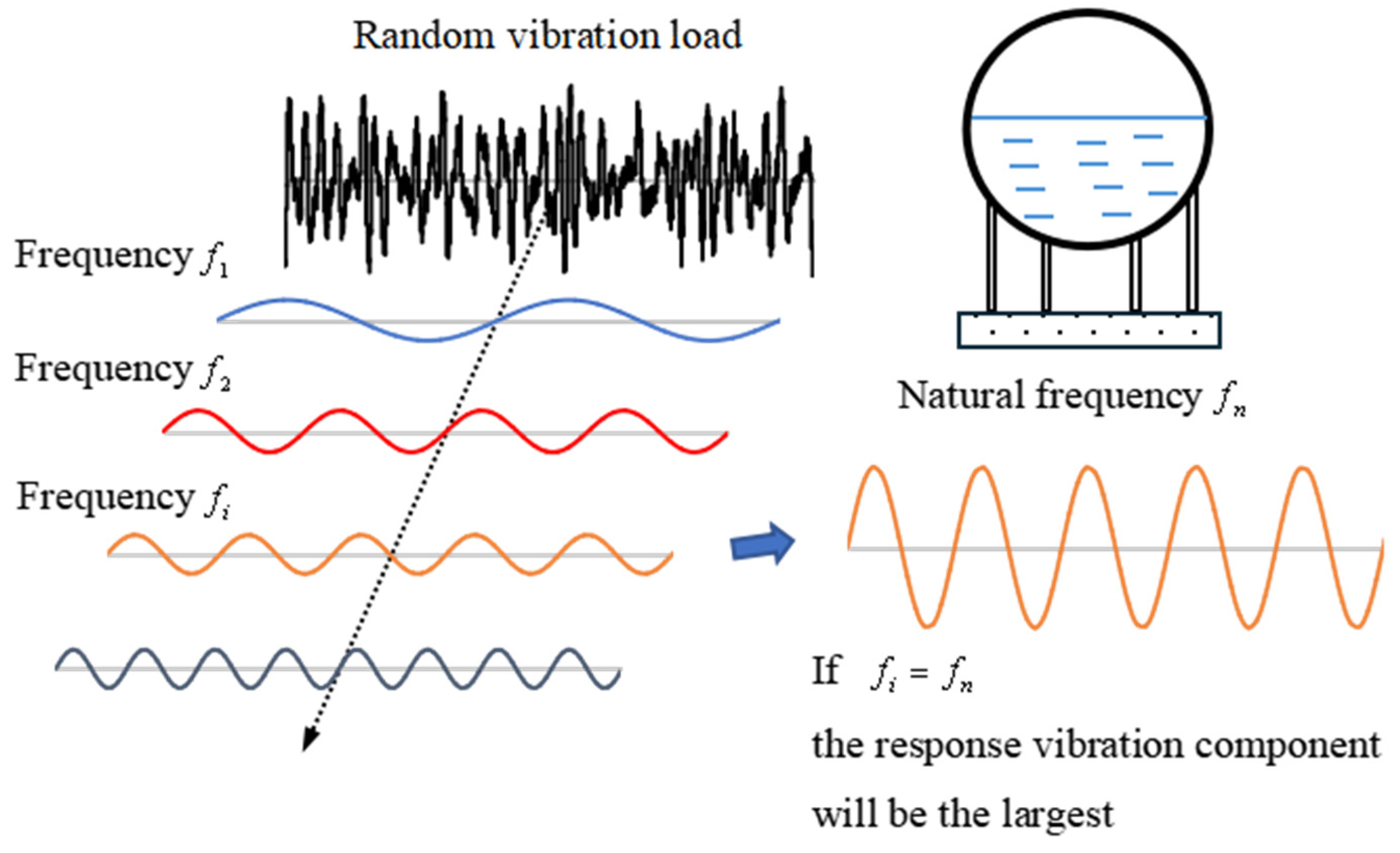
The random seismic excitation load can be transformed using Fourier transform, as shown in Figure 2, which reveals that the seismic load comprises multiple frequency components. Among these components, if a certain frequency component fi is the closest to the natural frequency fn of the spherical water storage tank, the response vibration component of the tank caused by fi will be the largest.
However, a single TMD can only be tuned to one specific target frequency. While it is possible to install multiple TMDs to cover a wider range of excitation frequencies, this study focuses on a single TMD as a first step.
Therefore, by targeting the frequency component fi and effectively reducing the corresponding response vibration component, the overall response vibration of a spherical water storage tank can be significantly reduced.
Two significant issues must be resolved to achieve vibration control in TMD. The first was to determine the natural frequency fn of the spherical water storage tank targeted for control. The other is the development of a vibration control device designed to address the target frequency fn.

2.1. Natural Frequencies of a Spherical Water Tank

The main objective of this study is to investigate the potential for real-time control of the dominant vibration components of a spherical water storage tank by targeting only the vibration modes corresponding to lower natural frequencies and reducing them using a TMD system. To this end, a simplified analytical model was employed.
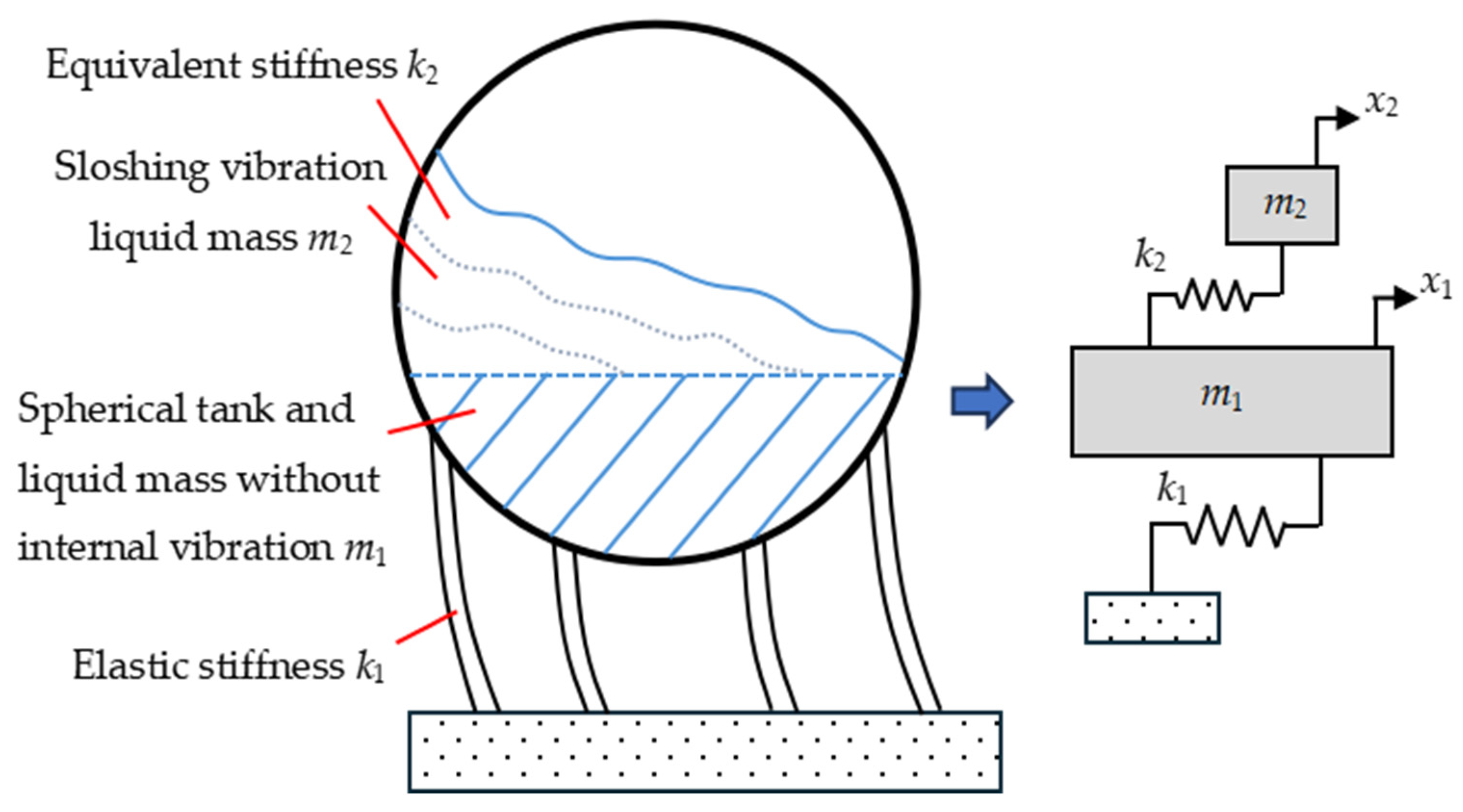
To analyze the natural vibration characteristics of the spherical water storage tank shown in Figure 1, a vibration analysis model was devised, as illustrated in Figure 3.
As shown in Figure 3, when a seismic excitation occurs, the spherical tank sways horizontally, causing a bending deformation in the supporting columns. The stiffness against the bending deformation of the columns is denoted as k1. The water inside the spherical tank was assumed could be divided into the upper and lower parts. The lower part of the water moves together with the spherical tank during internal vibrations with no relative motion between them and can be considered fixed to the tank. The combined mass of the lower water and spherical tank is denoted as m1. The upper part of the water experienced sloshing vibrations along with seismic excitation, and its mass is represented as m2. Equivalent stiffness k2 corresponds to the restoring force that returns the sloshing water to its original equilibrium position.
In this study, as a first step of the research, the spherical water tank was simplified into a two-degree-of-freedom model [9], in order to apply the simplest possible model to the vibration control problem. The natural vibration analysis model of the spherical water storage tank is shown on the right side of Figure 3. Here, x1 represents the displacement of the spherical tank, and x2 represents the displacement of the sloshing water inside the tank. The effect of vibration damping was neglected in the initial stages of this study.
The equations of motion corresponding to the vibration model shown in Figure 3 are as follows:
m 1 x ¨ 1 + k 1 x 1 k 2 x 2 x 1 = 0
m 2 x ¨ 2 + k 2 x 2 x 1 = 0
By rearranging Equations (1) and (2), the following expressions are obtained:
x ¨ 1 + k 1 m 1 x 1 k 2 m 1 x 2 x 1 = 0
x ¨ 2 + k 2 m 2 x 2 x 1 = 0
Here, the following symbols are introduced:
ω 11 2 = k 1 m 1
ω 22 2 = k 2 m 2
ω 12 2 = k 2 m 1
By applying Equations (5)–(7), the equations of motion are as follows:
x ¨ 1 + ω 11 2 x 1 ω 12 2 x 2 x 1 = 0
x ¨ 2 + ω 22 2 x 2 x 1 = 0
Here, considering excitation by a periodic signal with angular frequency, the response vibration displacements of mass blocks m1 and m2 are assumed as follows:
x 1 = A 1 e i ω t
x 2 = A 2 e i ω t
Here, A1 and A2 are the amplitudes of mass blocks m1 and m2, respectively. By substituting Equations (9) and (10) into Equations (8) and (9) and rearranging them, the following expressions are obtained:
A 1 ω 2 + A 1 ω 11 2 ω 12 2 A 2 A 1 = 0
A 2 ω 2 + ω 22 2 A 2 A 1 = 0
Rearranging Equations (12) and (13), they can be expressed in the following matrix form:
ω 2 + ω 11 2 + ω 12 2 ω 12 2 ω 22 2 ω 2 + ω 22 2 A 1 A 2 = 0 0
Because the amplitudes A1 and A2 are not equal to zero; hence, the following equation is obtained:
ω 2 + ω 11 2 + ω 12 2 ω 12 2 ω 22 2 ω 2 + ω 22 2 = 0
By expanding and rearranging Equation (15), the following equation related to the excitation angular frequency is obtained:
ω 4 ω 11 2 + ω 12 2 + ω 22 2 ω 2 + ω 11 2 ω 22 2 = 0
Furthermore, by solving the quadratic equation related to ω 2 , the first natural frequency ω 1 and the second natural frequency ω 2 are obtained and expressed by the following equations:
ω 1 2 = 1 2 ω 11 2 + ω 12 2 + ω 22 2 ω 11 2 ω 22 2 2 + 2 ω 12 2 ω 11 2 ω 22 2
ω 2 2 = 1 2 ω 11 2 + ω 12 2 + ω 22 2 + ω 11 2 ω 22 2 2 + 2 ω 12 2 ω 11 2 ω 22 2
Here, by calculating m1, m2, k1, and k2 using Equations (5)–(7) and substituting them into Equations (17) and (18) and can be calculated.

2.2. Vibration Control Device for a Spherical Water Tank

In conventional studies on TMD systems incorporating damping devices have been widely reported. However, introducing damping devices into TMD systems can not only complicate the structure of the vibration control device but also lead to potential changes in damping performance over time due to variations in the damping ratio. Therefore, this study proposes a TMD system without the use of damping devices, aiming to reduce the dominant vibration components corresponding to the lower natural frequencies of a spherical water tank.
Generally, spherical water storage tanks are used to fill water up to a certain height along the vertical direction. That is, the upper internal space of a spherical tank is often left empty during use.
In this study, a TMD vibration control device composed of spring and mass elements was devised and developed to effectively utilize the upper internal space of the spherical water storage tank, as shown in Figure 4.
As shown, a circular plate was installed on the upper part of the spherical water storage tank, and a square metal mass block was placed on top of the plate. Four ball casters were attached to the bottom of the mass block to allow free movement in any direction on the plate surface. In addition, elastic springs were attached to each side of the mass block, with the opposite ends of the springs fixed near the boundary of the circular plate.
The analytical model of the newly constructed vibration system is shown in the lower-right corner of Figure 4. Variables x1, x2, m1, m2, k1, and k2 have the same meaning as those in Figure 3. where x3 represents the displacement of the TMD mass block, m3 represents the mass of the TMD mass block, and k3 represents the TMD spring constant. xt denotes the displacement owing to seismic excitation.
As shown in Figure 4, the vibration model has three degrees of freedom. For the purpose of analyzing the main vibration components, viscous damping is neglected, and the coupling stiffness between each degree of freedom is also ignored.
The equations of motion for the vibration model shown in Figure 4 are as follows:
m 1 x ¨ 1 + k 1 x 1 k 2 x 2 x 1 k 3 x 3 x 1 = m 1 x t
m 2 x ¨ 2 + k 2 x 2 x 1 = 0
m 3 x ¨ 3 + k 3 x 3 x 1 = 0
By rearranging Equations (19)–(21), the following expressions are obtained:
x ¨ 1 + k 1 m 1 x 1 k 2 m 1 x 2 x 1 k 3 m 1 x 3 x 1 = x t
x ¨ 2 + k 2 m 2 x 2 x 1 = 0
x ¨ 3 + k 3 m 3 x 3 x 1 = 0
Here, using ω 11 2 and ω 12 2 , as defined in Equations (5)–(7), the following notations are introduced:
ω 33 2 = k 3 m 3
ω 13 2 = k 3 m 1
Therefore, the equations of motion can be written as follows:
x ¨ 1 + ω 11 2 x 1 ω 12 2 x 2 x 1 ω 13 2 x 3 x 1 = x ¨ t
x ¨ 2 + ω 22 2 x 2 x 1 = 0
x ¨ 3 + ω 33 2 x 3 x 1 = 0
Here, assuming excitation by a periodic signal with angular frequency ω , the response displacements of mass blocks m1, m2, and m3 as well as the external excitation displacement, were assumed as follows:
x 1 = A 1 e i ω t
x 2 = A 2 e i ω t
x 3 = A 3 e i ω t
x t = A t e i ω t
where A1, A2, and A3 are the amplitudes of the mass blocks m1, m2, and m3, respectively, and At is the amplitude of the external excitation. By substituting Equations (30)–(33) into Equations (27)–(29) and simplifying, the following equations are obtained:
A 1 ω 2 + A 1 ω 11 2 ω 12 2 A 2 A 1 ω 13 2 A 3 A 1 = A t
A 2 ω 2 + ω 22 2 A 2 A 1 = 0
A 3 ω 2 + ω 33 2 A 3 A 1 = 0
Equations (34)–(36) can be rearranged and expressed in the following matrix form:
ω 2 + ω 11 2 + ω 12 2 + ω 13 2 ω 12 2 ω 13 2 ω 22 2 ω 2 + ω 22 2 0 ω 33 2 0 ω 2 + ω 33 2 A 1 A 2 A 3 = A t 0 0
By solving the system of linear equations for the amplitude values A1, A2, and A3, the following equations are obtained:
A 1 = A t ω 2 + ω 22 2 ω 2 + ω 33 2 Δ
A 2 = A t ω 22 2 ω 2 + ω 33 2 Δ
A 3 = A t ω 33 2 ω 2 + ω 22 2 Δ
where Δ is the determinant of the matrix. Equation (38) indicates that when the external excitation frequency ω matches the apparent natural frequency ω 33 of the TMD, the amplitude of the spherical water tank A3 becomes zero. That is, when the condition ω = ω 3 is satisfied, theoretically, the amplitude of the spherical water tank becomes zero, indicating that the optimal vibration control effect can be achieved.
Among the response vibration components of a spherical water tank subjected to random seismic excitation, the component that matched the natural frequency ω n was the largest. Therefore, by designing the apparent natural frequency ω 33 of the new TMD to be equal to the spherical water tank’s natural frequency ω n , an effective vibration control effect can be achieved.
Therefore, in this study, a vibration-control device for a spherical water tank was designed and developed according to the procedure described below.
First, the natural frequencies of an actual spherical water tank were experimentally measured. Assuming that a typical spherical water tank is equipped with an automatic water-level control switch, the natural frequencies of the tank are considered constant.
Next, by referring to the primary frequency component distribution of typical earthquake waves, the target frequency ω n for the vibration control device was selected from the lower natural frequencies measured for the spherical water tank.
Subsequently, the apparent natural frequency ω 33 = k 3 / m 3 of the TMD was adjusted to match the target frequency ω n by tuning the mass m3 and spring constant k3 of the TMD.
Finally, by installing the configured TMD set as shown in Figure 4, the fabrication of the vibration control device was completed in the upper interior of the spherical water tank.
For the single TMD set shown in Figure 4, it is conceivable to add another TMD set in parallel beneath it, allowing the two TMDs to have different apparent natural frequencies and thus target different vibration frequencies for control. However, in this study, due to limitations such as the restricted upper space of the experimental spherical water tank, only a single TMD was considered as the first step of the research.

2.3. TMD Vibration Control Experiment Device for a Spherical Water Tank

In the industrial sector, spherical tanks used to store liquids such as LPG or propylene typically have diameters ranging from 10 to 20 m. However, spherical tanks used for water storage are generally smaller, with most having diameters of only a few meters. In this study, a spherical water tank with a diameter of 5 m is assumed, and a 1:10 scale model of the tank is fabricated to investigate its vibration control performance through shaking table experiments.
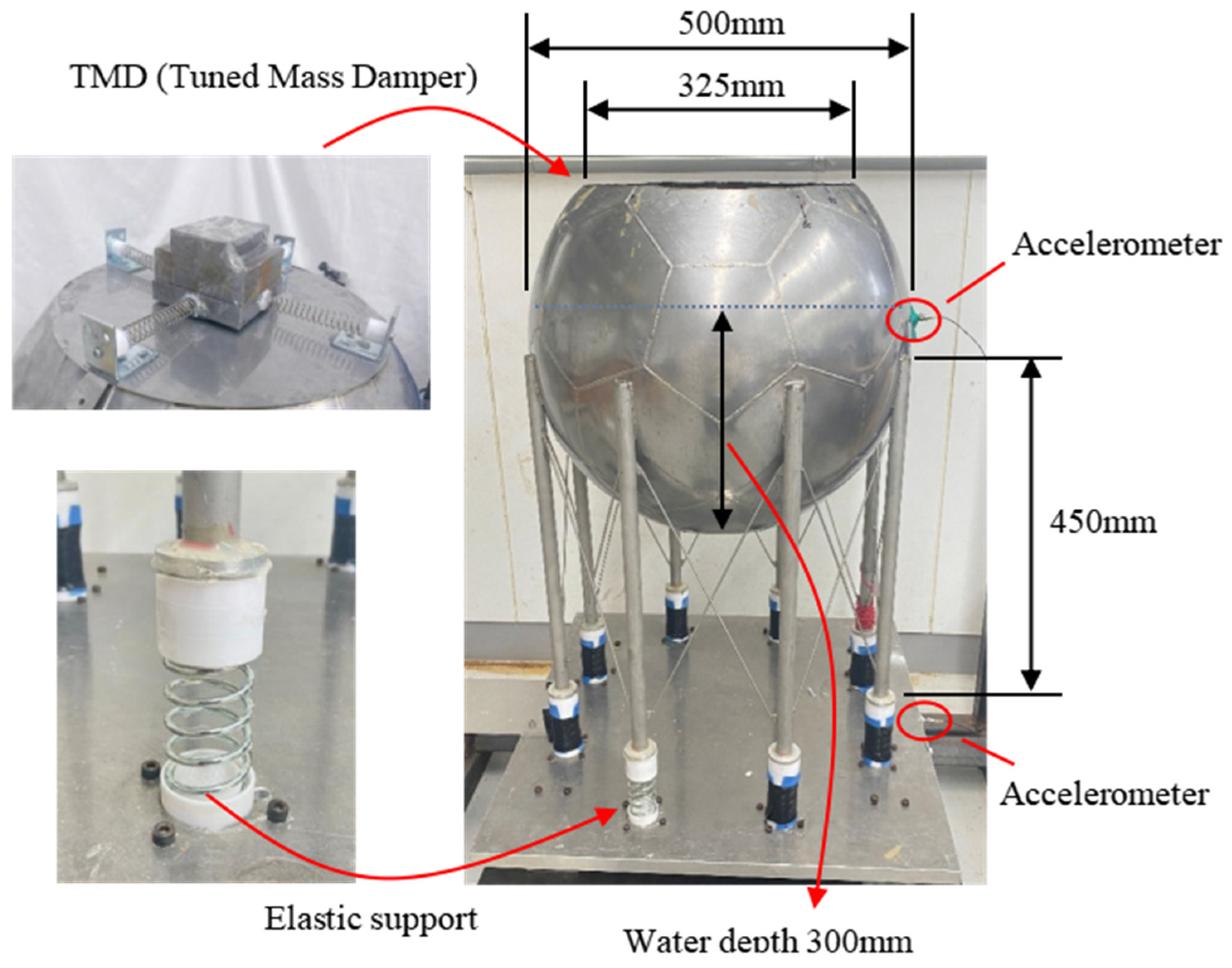
Figure 5 shows the fabricated spherical water tank. The spherical tank has an outer diameter of 500 mm, is made of stainless steel, and has a plate thickness of 1.0 mm. The supporting legs were used to fix eight spherical tanks made of stainless-steel circular pipes with a diameter of 30 mm and a wall thickness of 1.5 mm.
In actual spherical water storage tanks, the supporting legs are embedded into the horizontal ground, and their boundary conditions are considered to be close to elastic supports. Therefore, in this study, instead of directly bolting the fabricated spherical tank to a fixed metal base, each supporting leg was connected through eight elastic springs, as shown in Figure 5. Furthermore, to replicate boundary conditions as closely as possible, three types of elastic springs were used in separate vibration tests, and the spring that produced response acceleration values most similar to those of an actual tank was selected for use.
To install the TMD, the upper part of a spherical water tank was cut to create an opening with a diameter of 325 mm. Assuming that an automatic water level control switch is installed in the spherical water tank and the water depth is maintained at approximately 60% of the tank’s diameter, the internal water depth is set to 300 mm.
To measure the vibration characteristics, one accelerometer was attached to the surface of the spherical water tank, and the other to the shaking table. The difference between the two measured acceleration values was used to evaluate the vibration response of the spherical water tank.
Figure 6 shows the experimental verification system and measurement flowchart. As illustrated, the excitation signal is first generated by a signal generator that stores the seismic wave data in advance. The excitation signal is then sent to an amplifier to increase the amplitude. The amplified excitation signal was then sent to the shaking table. In the experimental setup, the spherical water tank was vibrated using a shaking table.
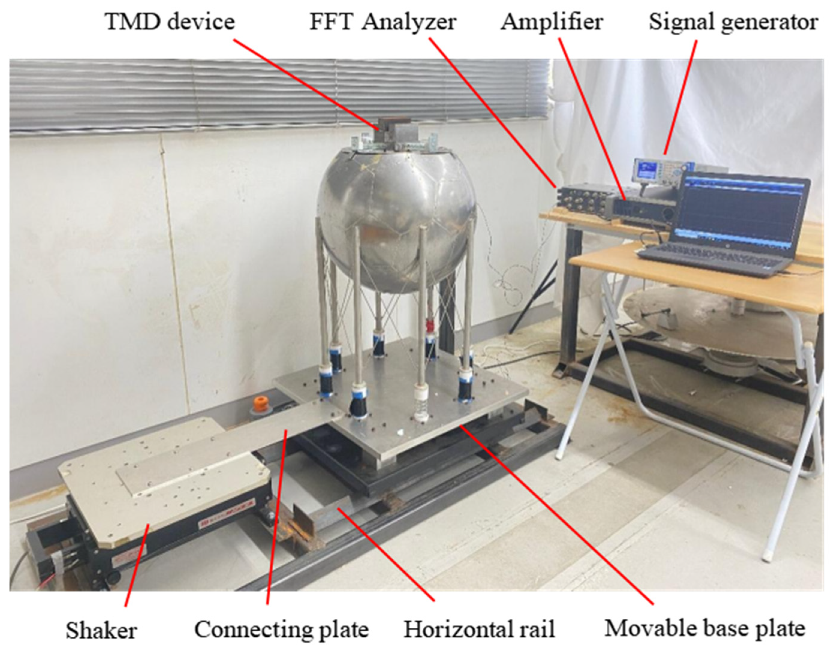
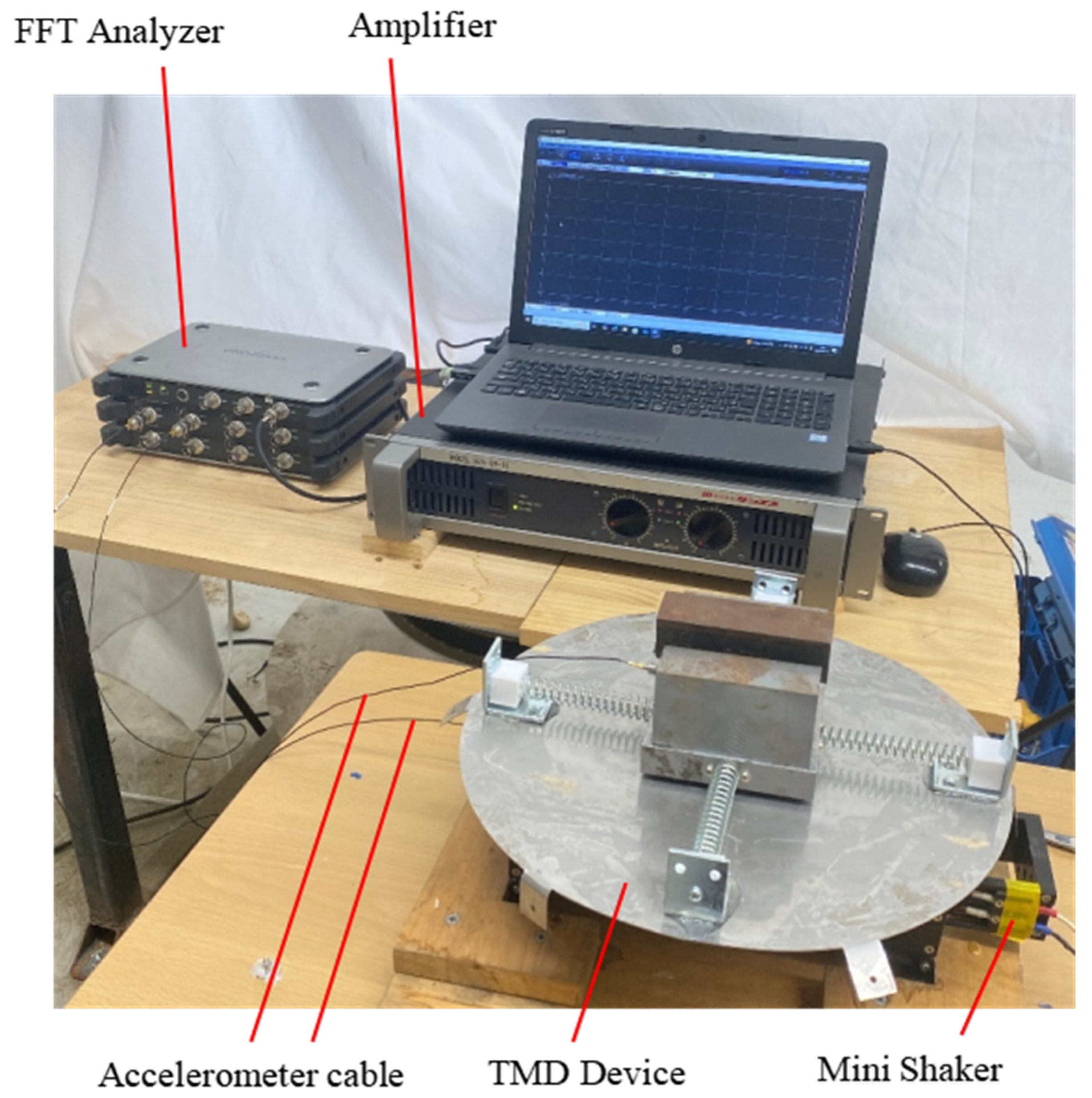
An image of the spherical water tank with the fabricated TMD vibration control device installed along with the measurement system is shown in Figure 7.
In this study, the most important indicator for evaluating the vibration of the spherical water tank is considered to be the relative vibration between the tank body and the fixed base. Therefore, as shown in Figure 6 and Figure 7, acceleration sensors are attached to both the spherical tank body and the fixed base, and the difference between the two acceleration values measured at the same time step, that is, the relative acceleration between the tank body and the fixed base, to evaluate the vibration response of the spherical water tank.
Acceleration sensors attached to the spherical water tank surface and shaking table base were used to collect real-time vibration measurement data. These data were sent to an FFT analyzer, processed in CSV format, and transferred to a measurement PC.
Finally, the CSV data were graphed on the PC, and the response vibration of the spherical water tank was evaluated using the difference between the two acceleration values.

2.4. Tuning of the TMD

To determine the vibration control target frequency, the natural frequencies of the spherical water tank can be calculated using Equations (17) and (18). However, in the case of an actual spherical water tank, it is challenging to accurately determine the specific parameters m1, m2, k1 and k2.
In this study, after qualitatively confirming the characteristics of the natural frequencies through Equations (17) and (18), the values of ω 1 and ω 2 were determined through actual measurement experiments.
Specifically, using the experimental setup shown in Figure 7, sweep excitation was applied from zero to a certain frequency range. The relative displacement response of the spherical water tank with respect to a fixed base was measured, and the frequencies at which the peak responses occurred were used to determine the natural frequencies.
However, in the case of an actual spherical water storage tank, modal analysis can be conducted using hammering test measurements to determine its natural frequencies.
However, the apparent natural frequency ω 33 of the TMD can be directly obtained from Equation (25). However, as shown in Figure 4 and Figure 5, four elastic springs were attached orthogonally to the mass block of the TMD, and accurately determining spring constant k3 along a single axis was complicated.
Therefore, in this study, a sweep excitation test was conducted on the TMD alone, as shown in Figure 8, and the measured natural frequency ω 33 was repeatedly adjusted by modifying the mass of the mass block until it matched the target frequency ω n .
In actual spherical water tanks, it is assumed that an automatic water level control switch is installed, and thus, the natural frequency of the spherical tank during routine operation and maintenance is considered relatively stable. Thus, in practical settings, the relationship ω 33 = ω n obtained through the TMD natural frequency measurement and adjustment experiment shown in Figure 8 can be considered relatively stable.

2.5. The Experimental Earthquake Excitation Signal

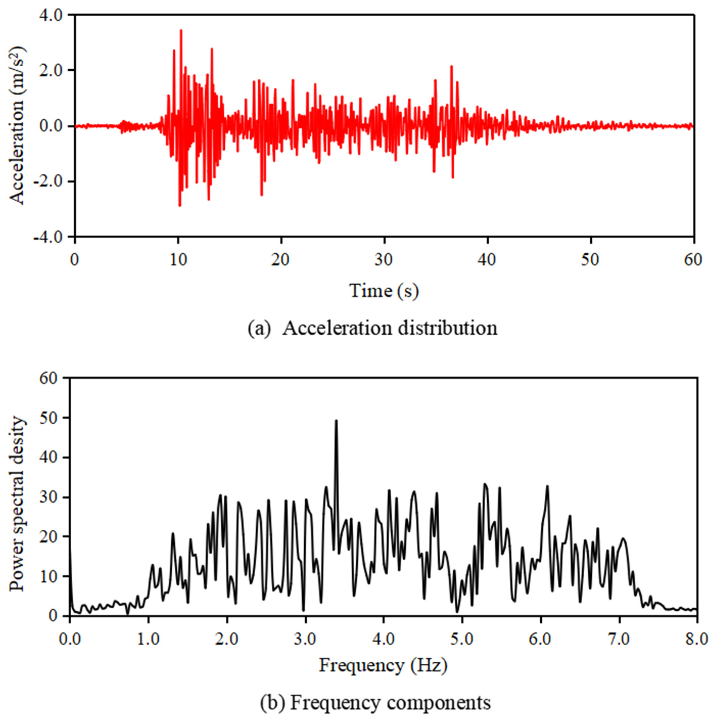
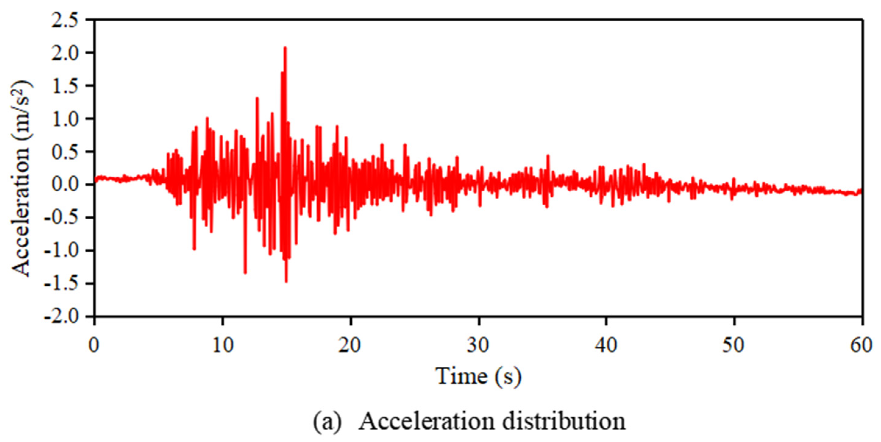
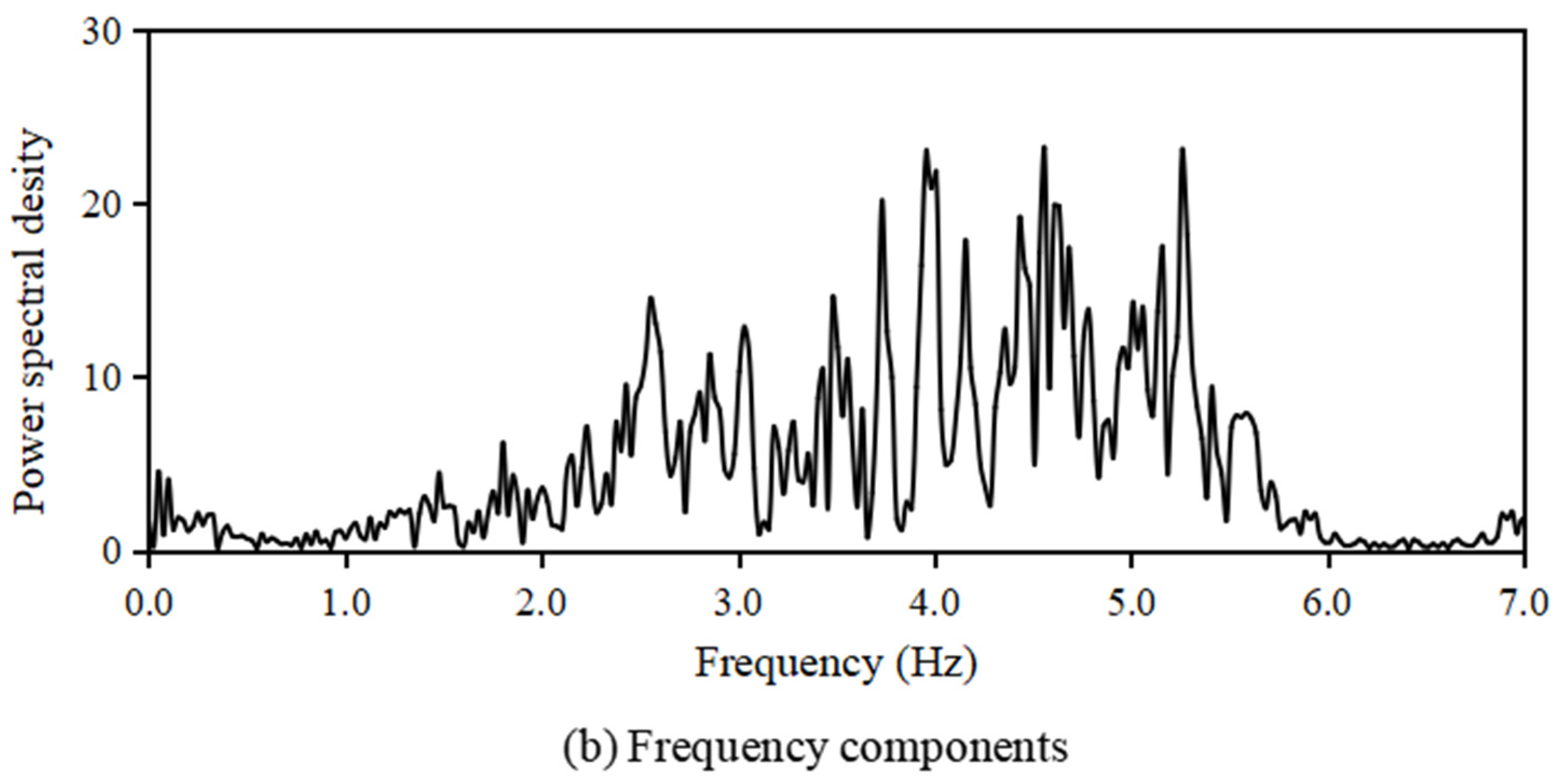
The acceleration waveforms of the seismic excitations used in the validation experiments are shown in Figure 9 and Figure 10. Figure 9 shows the acceleration waveform and frequency components of the El Centro NS earthquake wave, whereas Figure 10 shows the acceleration waveform and frequency components of the Taft NW earthquake wave.
Looking at the natural earthquake waves shown in Figure 9 and Figure 10, the primary frequency components of the El Centro NS wave are distributed in the frequency range of 1.0–7.5 Hz, while those of the Taft NW wave are distributed in the range of 1.0–6.0 Hz. This indicated that they possessed random excitation characteristics.

2.6. Quantitative Evaluation of Response Acceleration Due to Seismic Excitation

The response acceleration results of the spherical water tank obtained from the seismic excitation exhibited a random distribution, making it impossible to directly compare the different response acceleration results.
In this study, to quantitatively evaluate the vibration control effect of a spherical water tank, the standard deviation S of the response acceleration, defined by the following equation, was used as the evaluation criterion:
S = 1 N i = 1 N a i a a v e r 2
where ai is the measured value of the vibration response acceleration, aaver is the average value of the measured values ai, and N is the number of sample points in the measurement experiment.

3. Results and Discussions

To verify the performance of the proposed TMD vibration control system for the spherical water tank in this study, a scaled-down spherical water tank equipped with the proposed TMD is tested on a shaking table under seismic excitation using actual earthquake waves to examine the detailed vibration control performance.

3.1. The Vibration Damping Effect of TMD

The target vibration frequency for control was first determined to verify the vibration control performance of the spherical water tank. Subsequently, the natural frequencies of the TMD were individually adjusted to match this target. Subsequently, the TMD was installed on top of the spherical water tank to assemble a vibration-controlled spherical tank. Subsequently, a shaking table test using actual seismic loads was conducted, and the vibration control performance was evaluated based on the difference in the response acceleration between the spherical water tank and the shaking table.

3.1.1. Natural Frequency Tuning for TMD

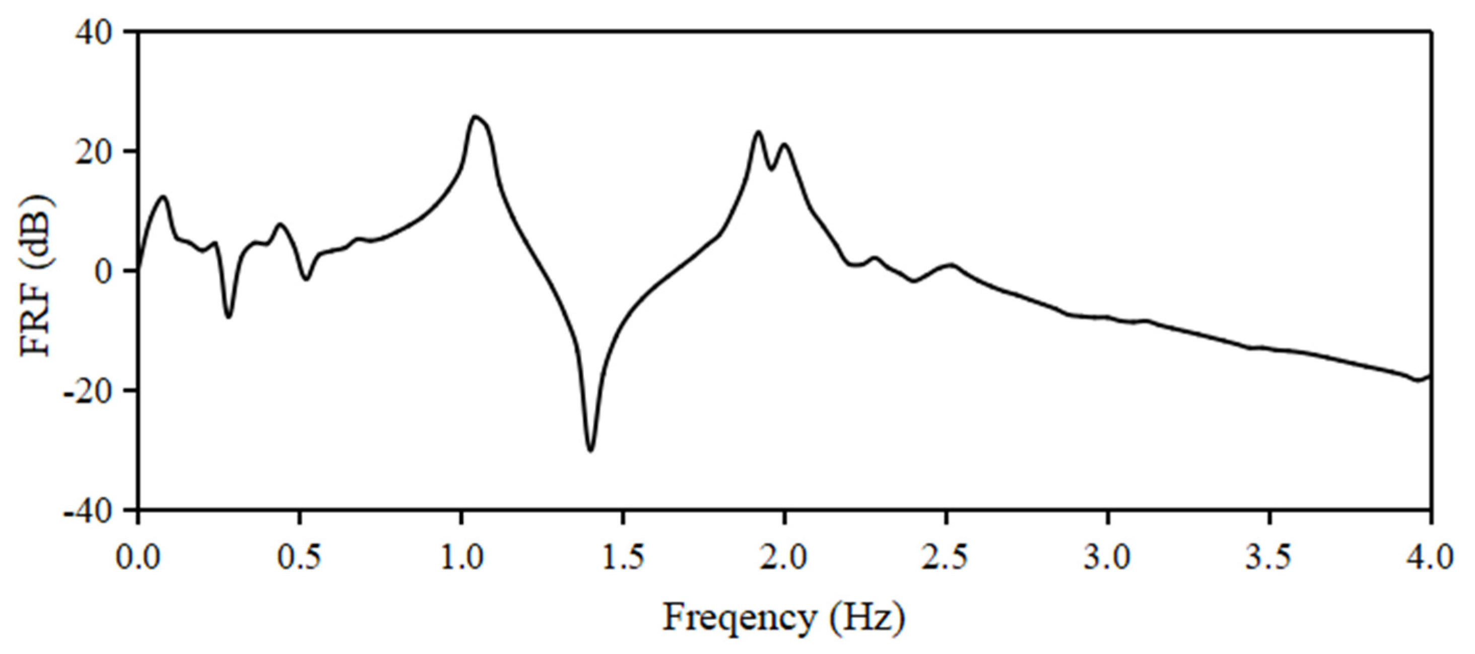
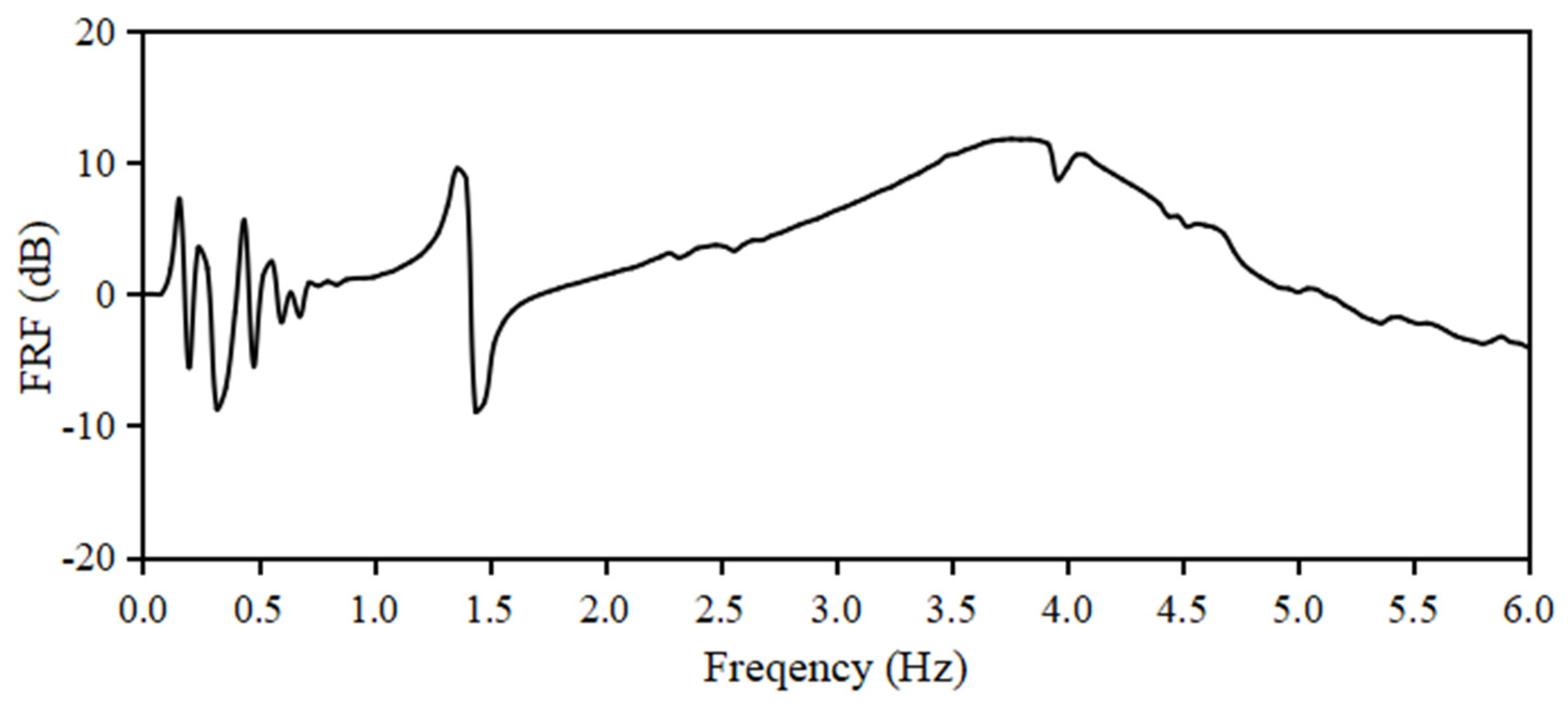
As shown in Figure 7, the spherical water tank body was fixed onto a shaking table, and a sweep excitation test was conducted. The resulting frequency responses obtained from the tests are shown in Figure 11. As shown, the spherical water tank has two natural frequencies: the first natural frequency ω 1 = 1.04   H z , and second natural frequency ω 2 = 1.98   H z .
Here, referring to the fact that the central frequency range of the actual earthquake waves shown in Figure 9 and Figure 10 is approximately 3–4 Hz, the second natural frequency ω 2 = 1.98   H z was chosen as the vibration-control target frequency.
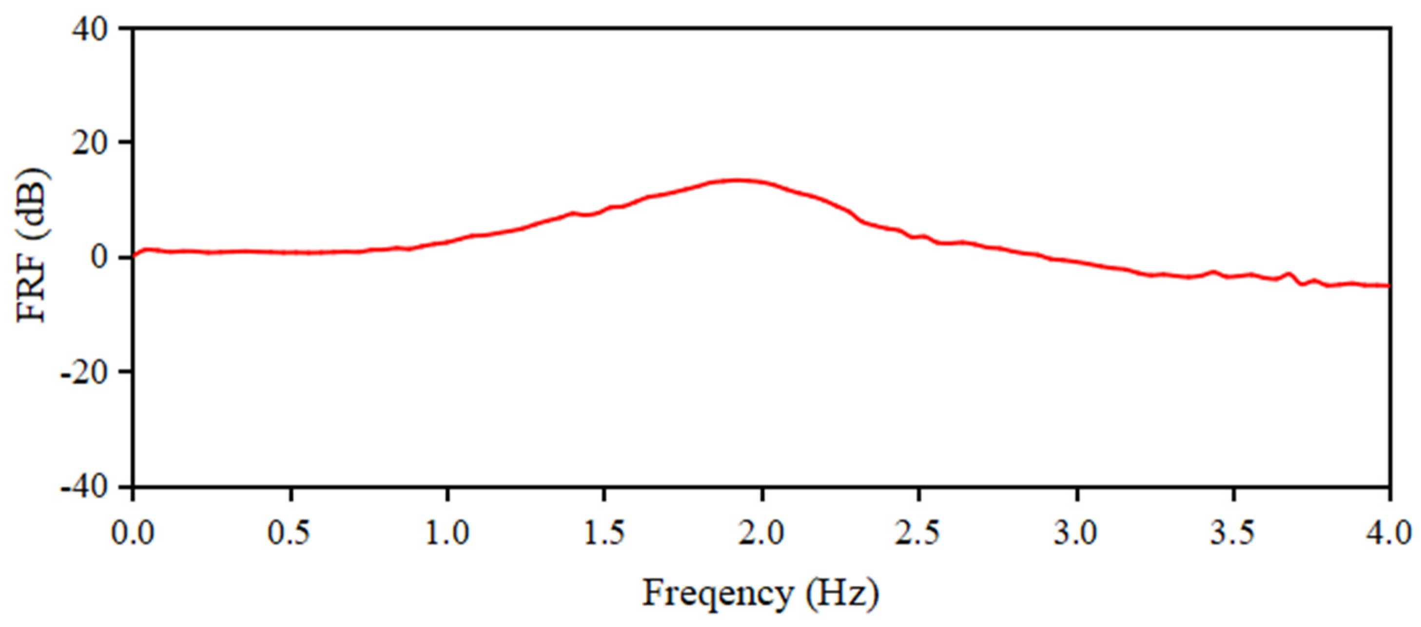
Using the experimental setup shown in Figure 8, the mass of the TMD was iteratively adjusted so that its natural frequency would match ω 33 = 1.98   H z . The frequency response results after the adjustment, shown in Figure 12, it is confirmed that the natural frequency successfully matches the ω 33 = 1.98   H z .
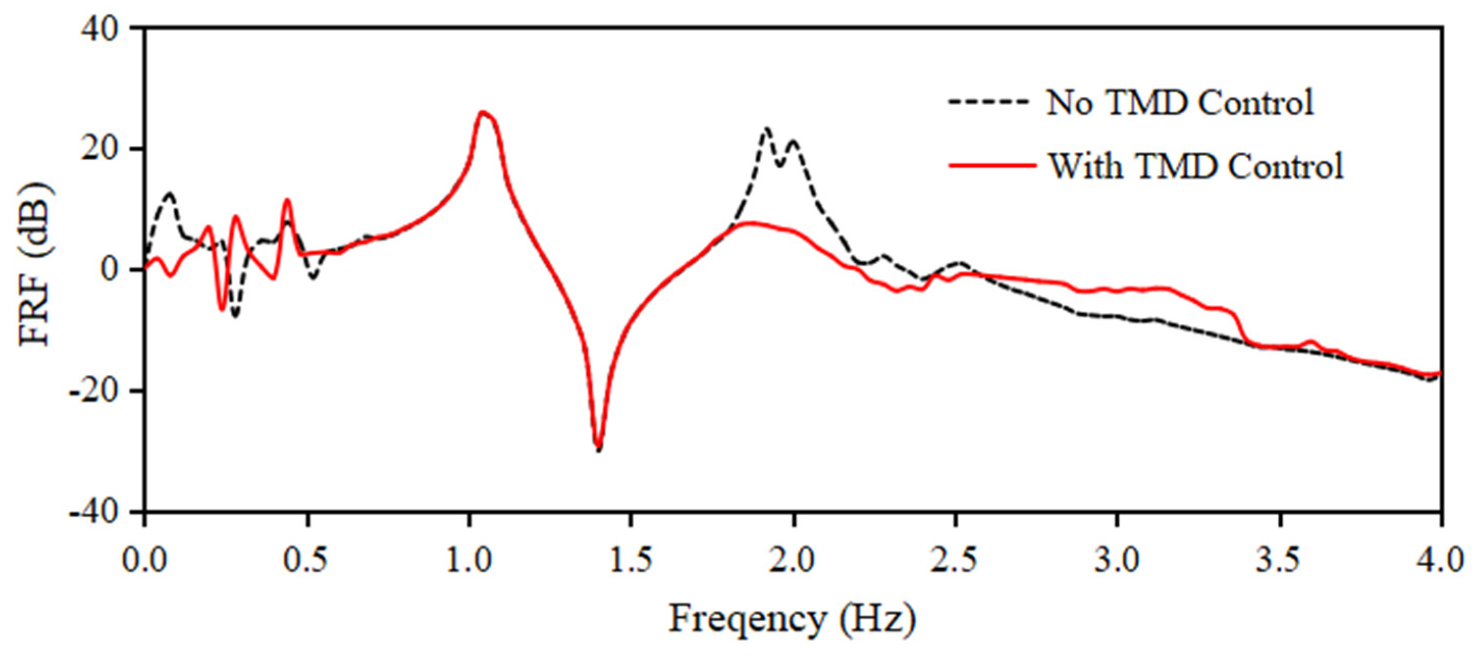
For verification, the TMD with the adjusted mass was mounted on top of a spherical water tank and sweep vibration tests were conducted under two conditions: one where the TMD mass block was fixed with tape (thus disabling the vibration control function), and another where the TMD was left free (thus enabling the vibration control function). The resulting frequency–response data are shown in Figure 13. In Figure 13, the red solid line represents the case with the TMD’s vibration control function, whereas the black dashed line represents the case without the vibration control function.
Figure 13 shows that the frequency response value in the case using the TMD vibration control function (red solid line) is clearly smaller around the vibration control target frequency of 1.98 Hz compared to the case without the TMD vibration control function (black dashed line). This confirms that the TMD contributes to the vibration control effect on the response acceleration around the target frequency of the spherical water tank.

3.1.2. Vibration Control Performance of Spherical Water Tanks in a Seismic Environment

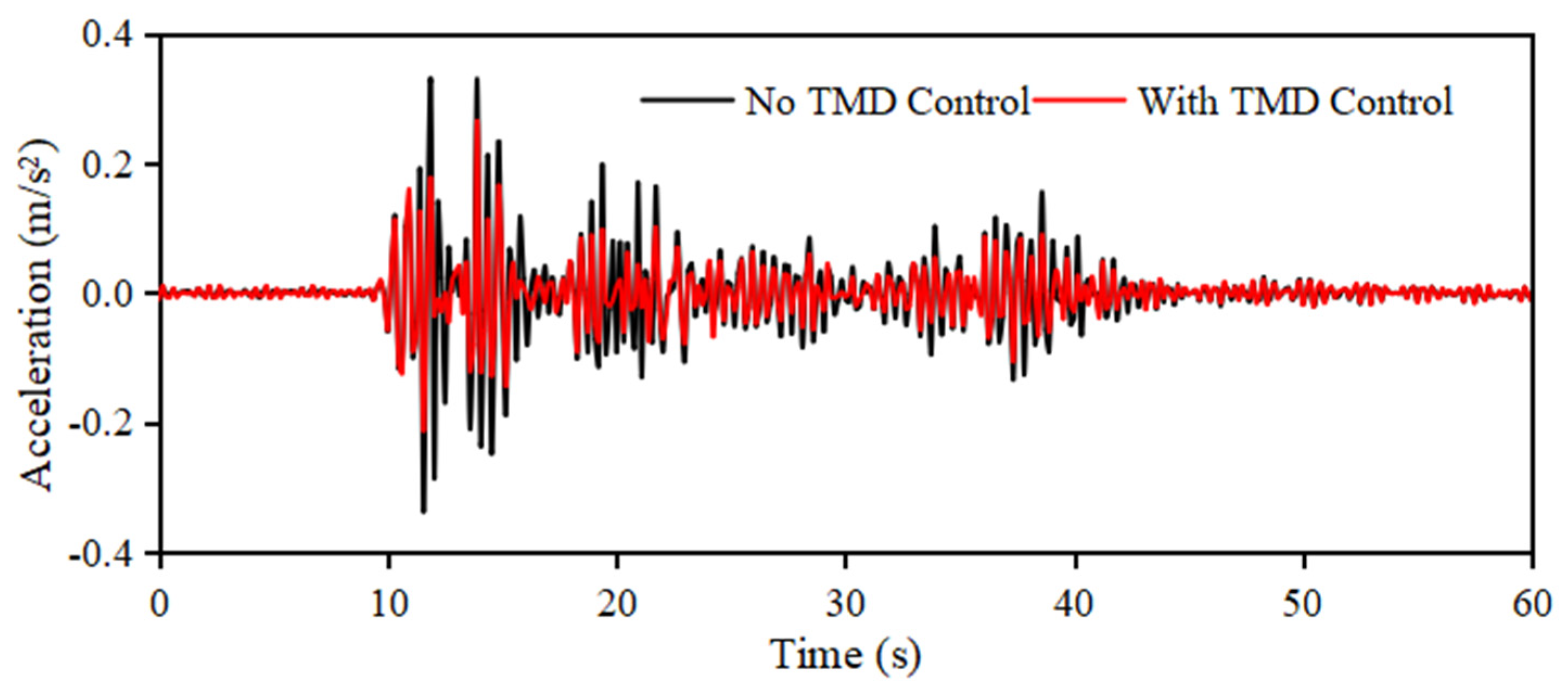
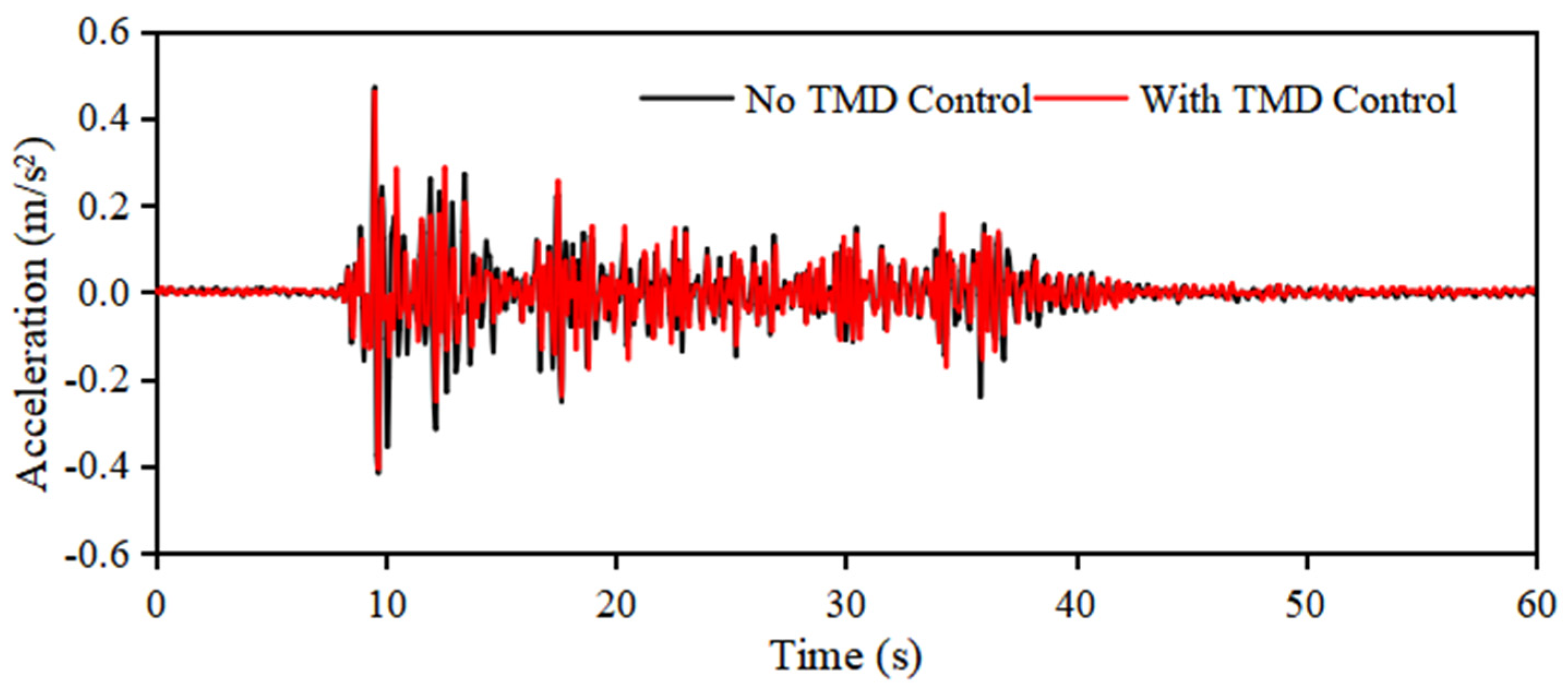
To verify the vibration control effect of the spherical water tank during an earthquake, shaking experiments were conducted on the experimental setup shown in Figure 7 using the EI Centro NS earthquake wave, which was divided into two cases: one without the TMD vibration control function, and the other with it. Acceleration sensors were attached to the surfaces of the spherical water tank and base. The difference between the response acceleration values measured by the two acceleration sensors was used to evaluate the vibration control effect; the results are shown in Figure 14.
In Figure 14, the black line represents the measured response acceleration for the case without the TMD vibration control function, whereas the red line represents the measured response acceleration for the case with TMD.
The standard deviation of acceleration calculated by Equation (41) is used to quantitatively compare the magnitudes of the random response acceleration values shown in Figure 14. The standard deviation of the black line was 0.062 m/s2, whereas that of the red line was 0.040 m/s2. This corresponded to a vibration control effect, which was expressed as a reduction rate of approximately 34.87%.
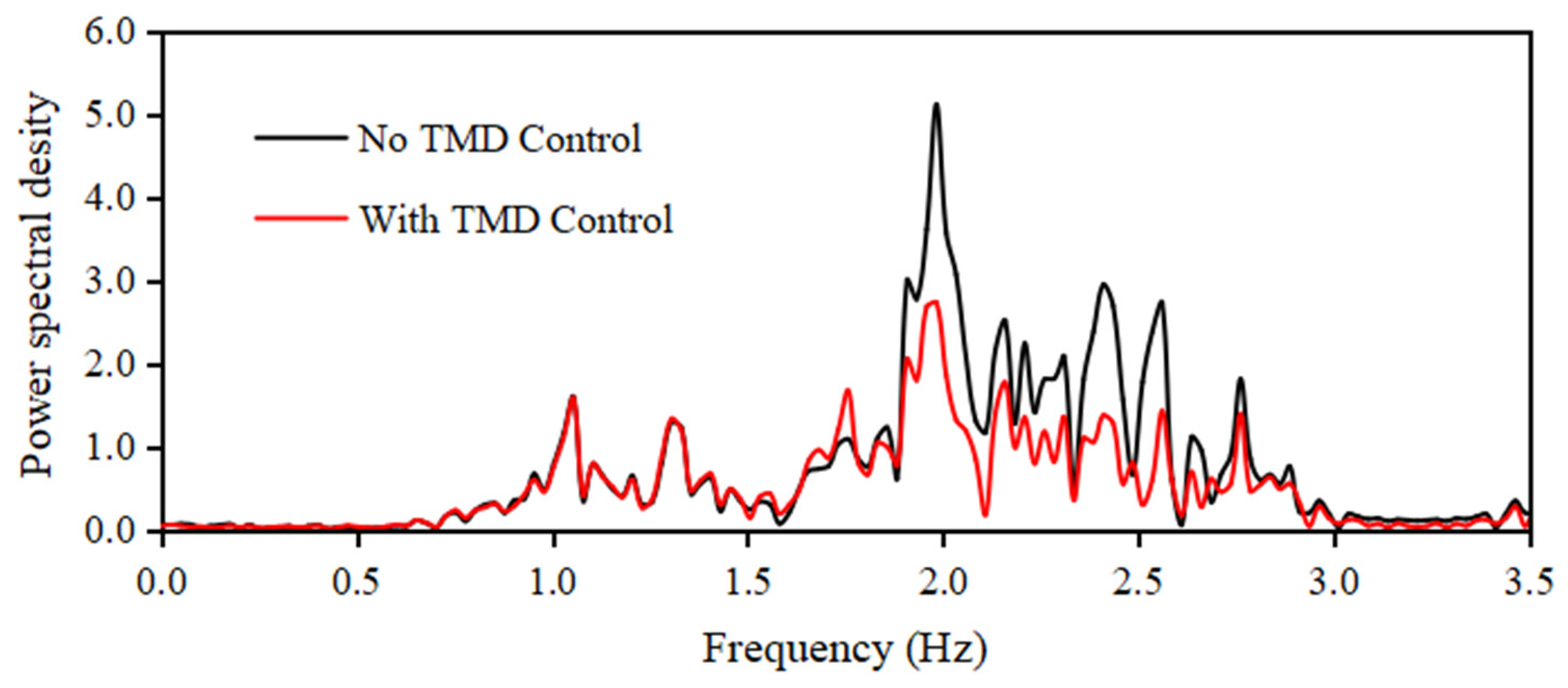
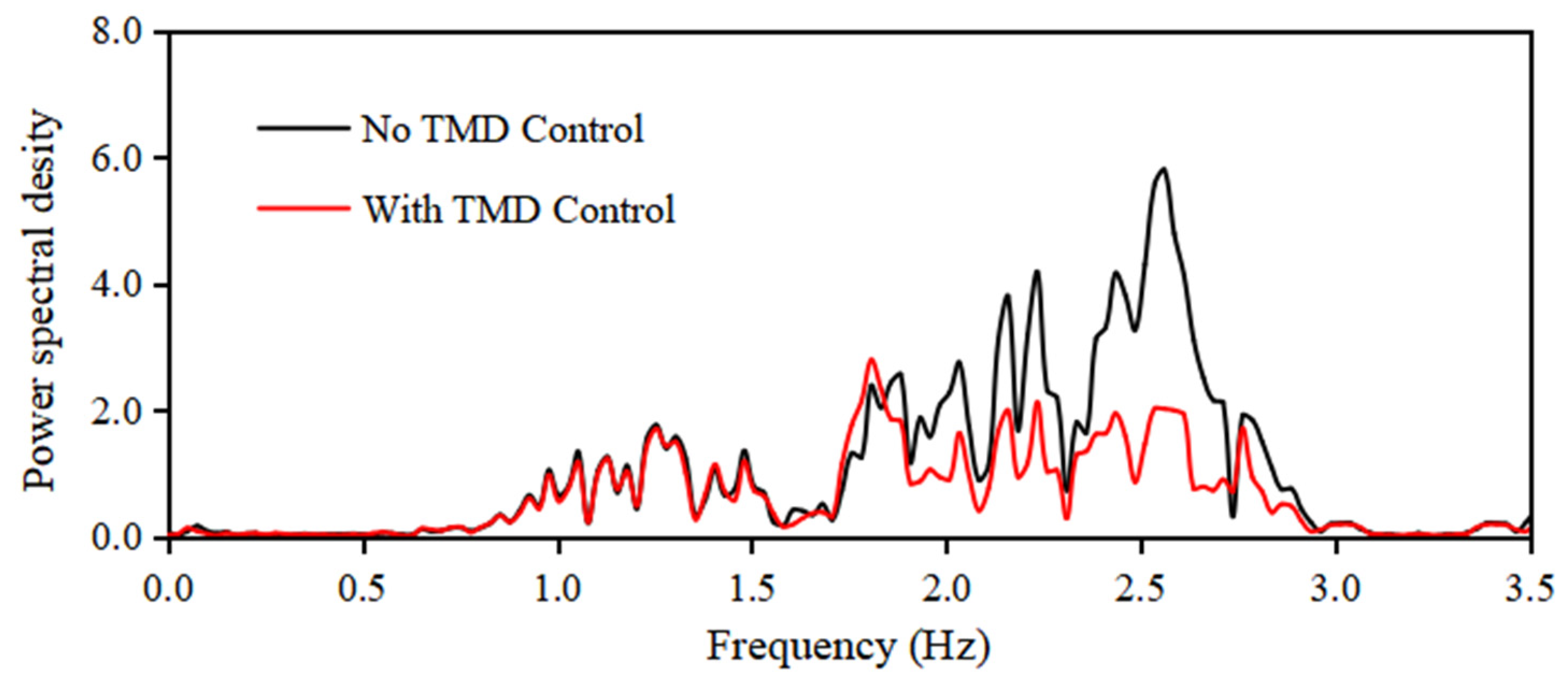
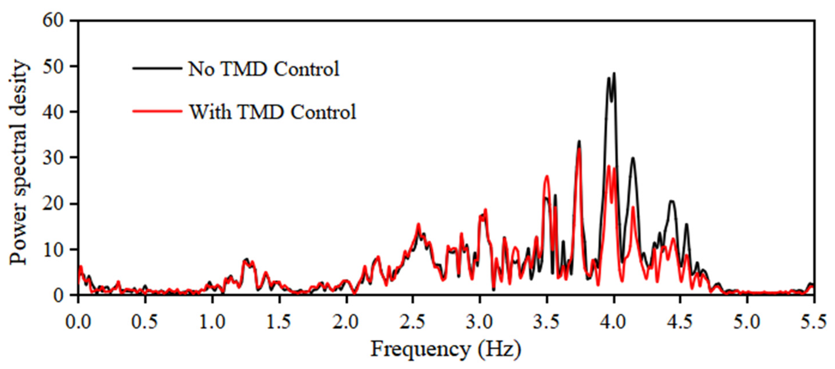
Furthermore, a Fourier transform was performed on the response acceleration results, as shown in Figure 14. The frequency response of the resulting acceleration values is shown in Figure 15.
Figure 15 shows that, compared to the case without the TMD control function (black line), the frequency response values in the case using the TMD, (red line) are significantly smaller. In particular, the frequency response around the vibration control target frequency of 1.98 Hz shows the greatest reduction. This demonstrates the vibration control effect achieved using the TMD.
Furthermore, influenced by the primary frequency components of the EI Centro NS earthquake wave shown in Figure 9, a significant reduction in the frequency response values was observed in the 2–3 Hz frequency range.

3.2. The Effect of Structural Conditions on the Spherical Water Tank

Based on the verification results presented in the previous section, the vibration control effect of the TMD was confirmed when the natural frequency of the spherical water tank was set to a vibration control target frequency of 1.98 Hz.
To examine the influence of different target frequencies on the vibration control, the elastic springs on the support columns of the spherical water tank shown in Figure 5 were replaced with new springs. That is, the vibration control target frequency, which previously matched the natural frequency of the spherical water tank, was changed. Subsequently, following the same procedure described in the previous section, the variation in the vibration control effect of the spherical water tank was investigated.

3.2.1. Natural Frequency Tuning for TMD

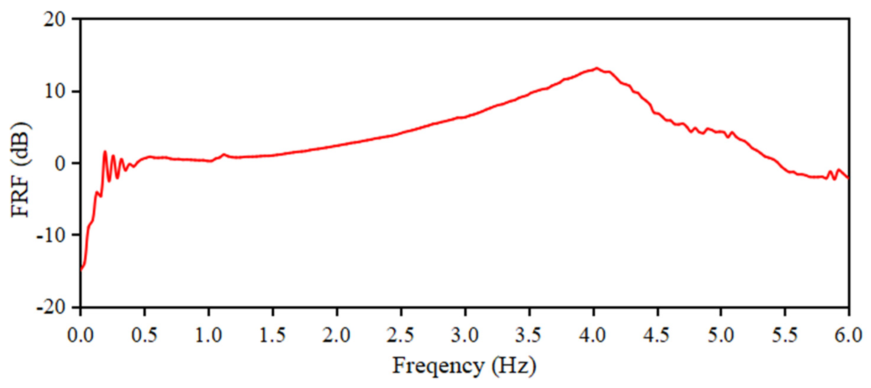
Figure 16 shows the frequency response results from the sweep excitation experiments conducted in a spherical water tank. Based on the frequency response results shown in Figure 16, the vibration control target frequency was set to the second natural frequency ω 2 = 4.02   H z .
Figure 17 shows the frequency response results obtained from the sweep excitation experiments conducted on the standalone TMD while adjusting the mass of the mass block. It can be confirmed that the natural frequency of the TMD was tuned to the target frequency of 4.02 Hz.
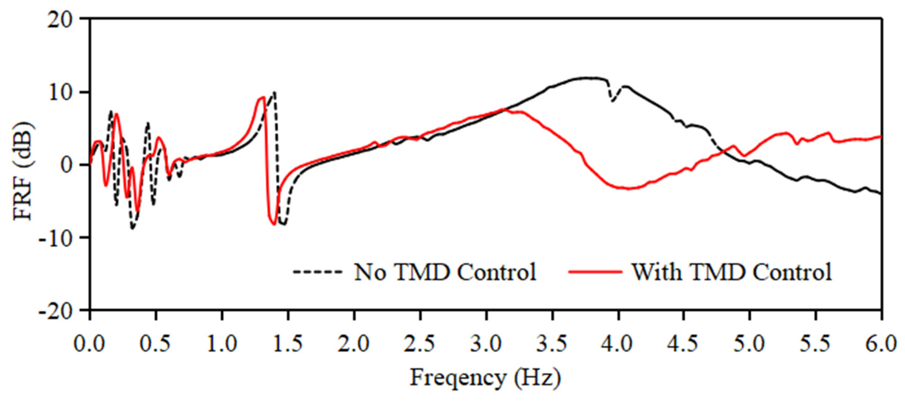
Figure 18 shows the frequency response results from the sweep excitation experiment on a spherical water tank equipped with a TMD. Figure 18 demonstrates that the frequency response values for the case using the TMD vibration control function (indicated by the red solid line) are significantly smaller around the target vibration control frequency of 4.02 Hz compared to the case without the TMD function (indicated by the black dotted line).

3.2.2. Vibration Control Performance of Spherical Water Tanks in a Seismic Environment

To verify the vibration control effect of the spherical water tank during an earthquake, two experiments were conducted on the spherical water tank test setup using the EI Centro NS seismic wave: one without the TMD vibration control function and the other with it. The differences in the measured response acceleration values obtained from the accelerometers attached to the surface of the spherical water tank and moving base were compiled, and the results are shown in Figure 19.
In Figure 19, the standard deviation of the acceleration calculated using Equation (41) is used to quantitatively compare the magnitudes of the random response acceleration values. The standard deviation for the black line was 0.294 m/s2, whereas that for the red line was 0.239 m/s2. This corresponded to a vibration control effect reduction rate of approximately 18.74%.
Furthermore, a Fourier transform was performed on the response acceleration results, as shown in Figure 19, and the resulting frequency responses of the acceleration values are shown in Figure 20.
Figure 20 demonstrates that compared to the case without using the TMD damping function (black line), the frequency response values in the case using the TMD (red line) are significantly smaller. In particular, the frequency response around the target damping frequency of 4.02 Hz was significantly reduced, demonstrating the effectiveness of the TMD in vibration control.
Therefore, even if the natural frequency of the spherical water tank changes owing to variations in the total mass or bending stiffness of the support columns, a vibration control effect can be achieved if the natural frequency of the TMD is set to match the target frequency.

3.3. The Effect of Seismic Excitation Direction on Vibration Control Performance

Early earthquakes that occur in nature cause random vibrations in various directions. However, in the vibration control experimental setup for the spherical water tank shown in Figure 7, the seismic excitation was applied only in a single direction.
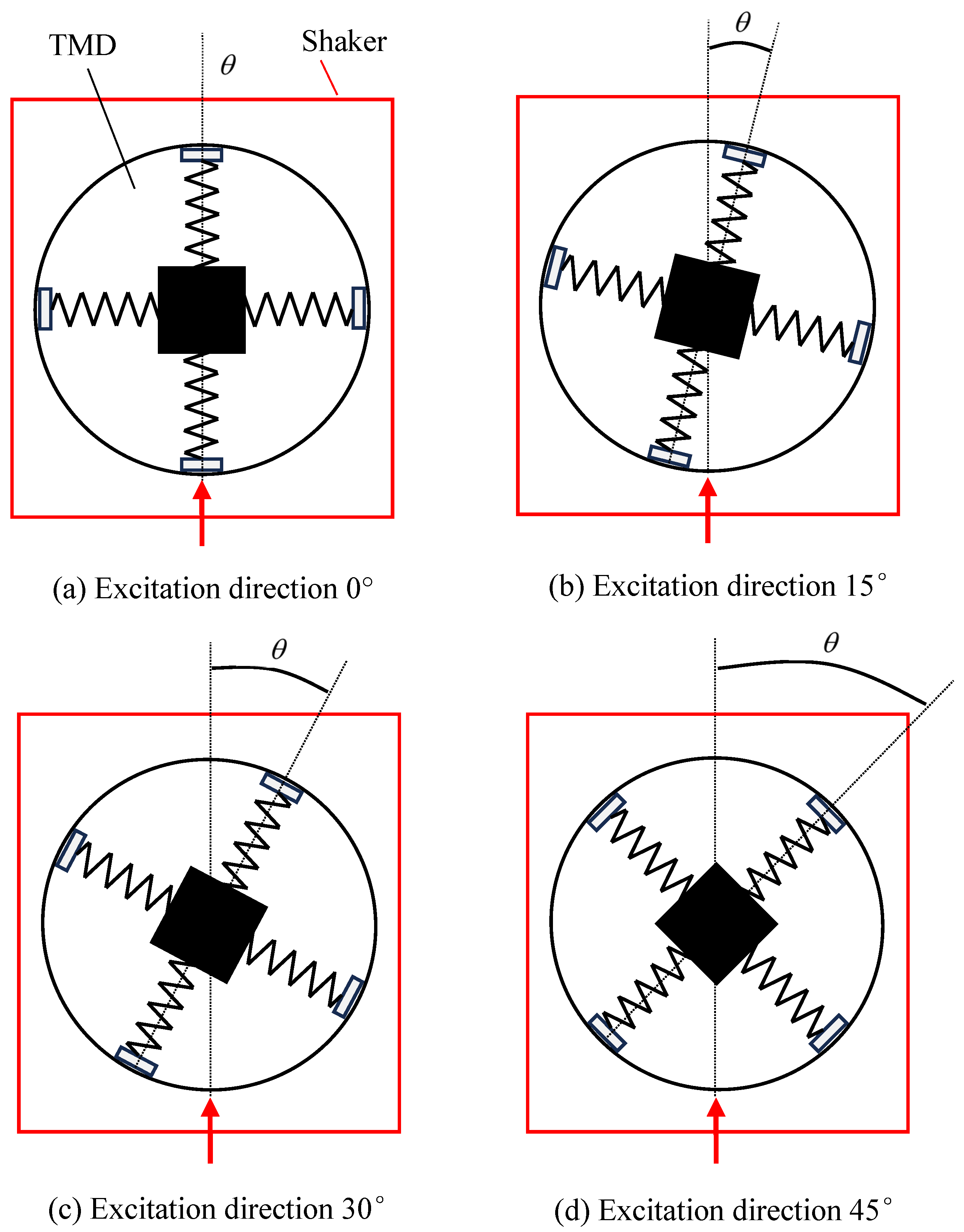
To examine the effect of different seismic excitation directions on the vibration control performance, the angle between the vibration table’s excitation axis and the TMD’s axis was set to 0°, 15°, 30°, and 45°, as shown in Figure 21, and vibration experiments were conducted for comparison. The vibration control target frequency was set to 1.98 Hz based on the natural frequency of the spherical water tank.
Moreover, owing to the symmetry of the spherical water tank and TMD, conducting measurement experiments over an angular range from 0° to 45° allows for the investigation of the vibration control characteristics in all directions around the tank.
Figure 21 shows the relative positional relationship between the vibration table and the TMD. The red rectangular outline represents the vibration table, and the area enclosed by the black lines indicates the TMD. The red arrows indicate the excitation direction of the vibration table.
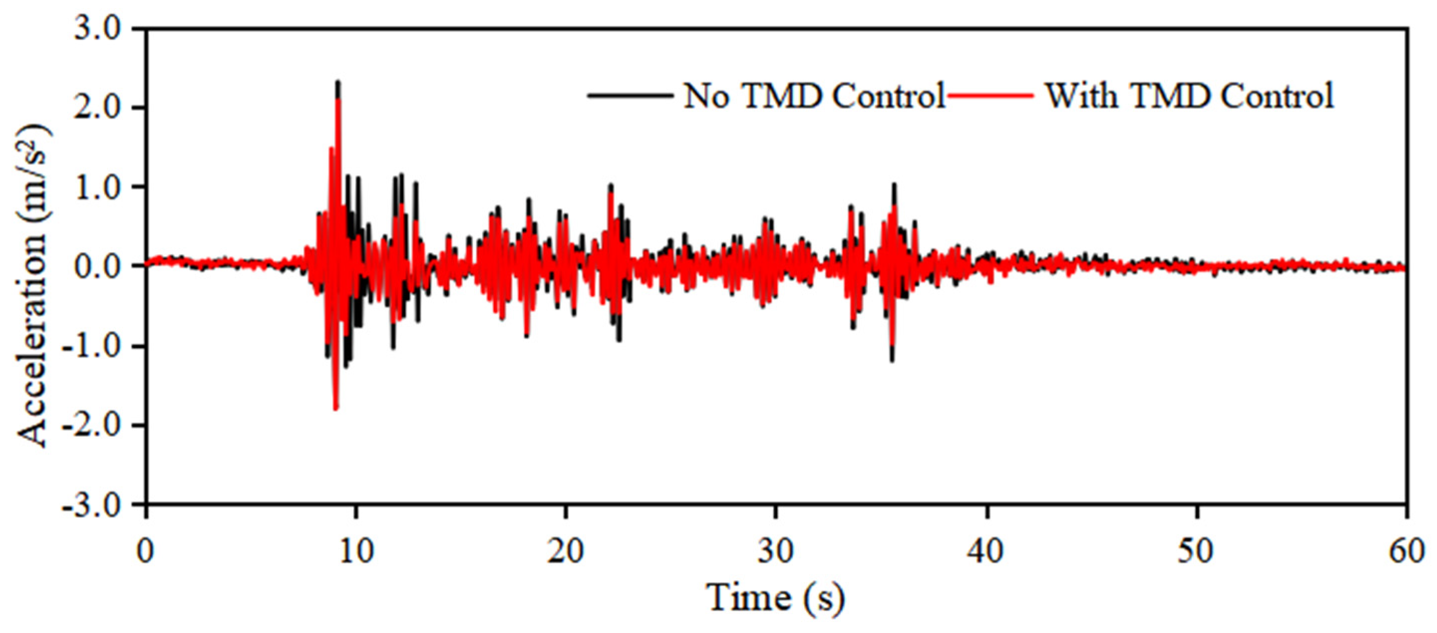
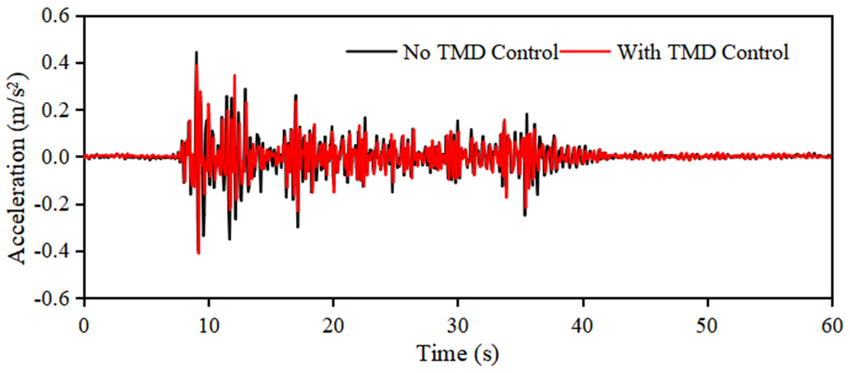
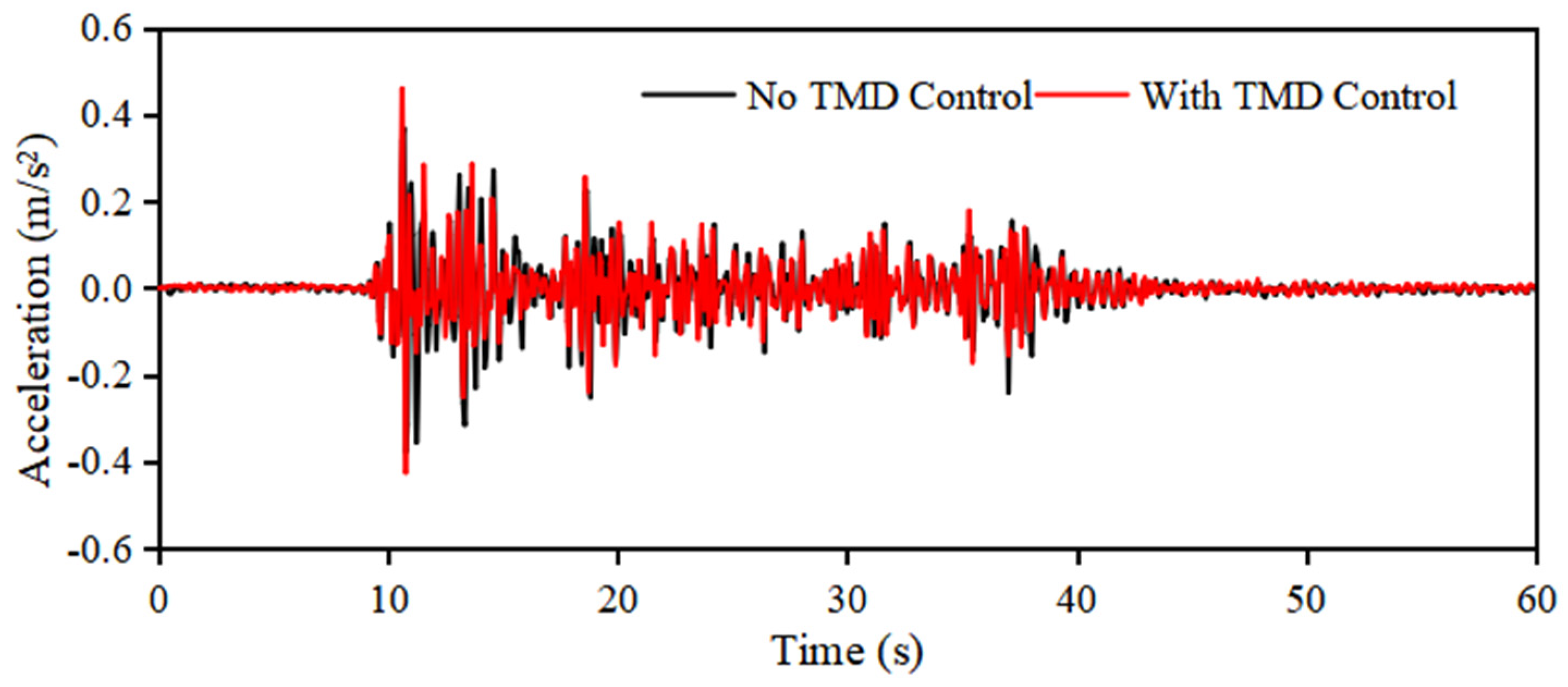
Figure 22, Figure 23, Figure 24 and Figure 25 show the measurement results obtained from the vibration experiments conducted in a spherical water tank with excitation angles of 0°, 15°, 30°, and 45°, respectively, as illustrated in Figure 21. The black lines represent the response acceleration when the TMD vibration control function was not used, whereas the red lines represent the measured response acceleration when the TMD vibration control function was active.
Comparing the response acceleration results in each figure, it can be seen that in all four excitation cases, the response acceleration indicated by the red lines tends to be smaller than that of the black lines, confirming the effectiveness of the vibration control.
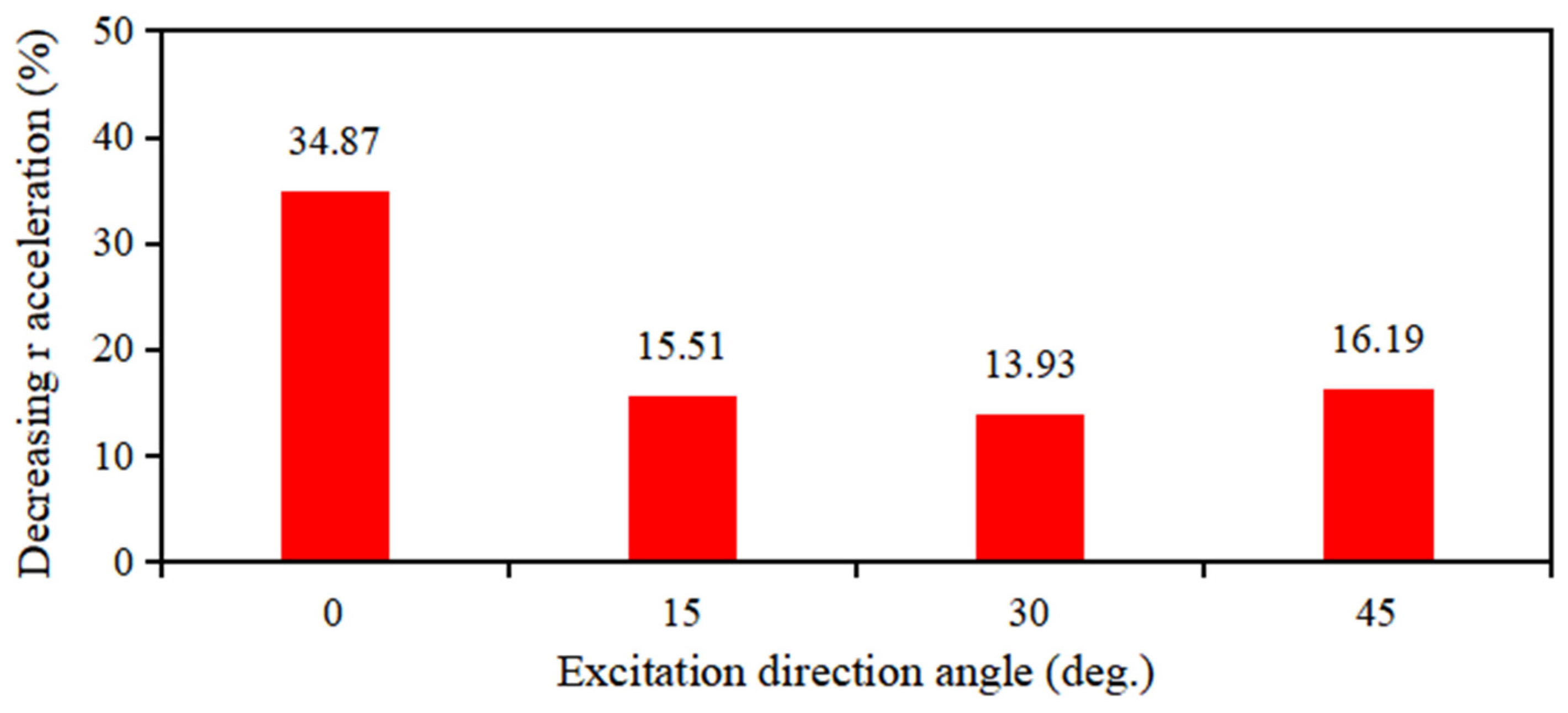
Furthermore, to evaluate the vibration control effect quantitatively, the vibration control effectiveness, expressed as the ratio of the standard deviation of the response acceleration between the cases with and without the TMD vibration control function, is summarized in Figure 26 for each experimental case.
Based on the comparison results shown in Figure 26, when the excitation angle was 0° and the TMD designed and fabricated with the natural frequency of the spherical water tank as the target frequency was used, the highest vibration control effect of 34.87% was achieved. When the excitation was applied at angles other than 0°, the vibration control effect decreased to some extent, with the control effects at excitation angles of 15°, 30°, and 45° being 15.51%, 13.93%, and 16.19%, respectively.
Thus, even when using a TMD designed and fabricated based on an excitation angle of 0°, it is evident that although the vibration control effect slightly decreases for seismic loads coming from directions other than 0°, the TMD still provides a definite vibration control effect.

3.4. Effects on Vibration Control Performance from Different Seismic Waves

In previous sections, the seismic control performance of a spherical water tank was verified using an EI Centro NS seismic wave. However, because seismic waves that occur in nature are highly complex, it is assumed that different seismic waves may have a significant impact on the vibration control performance.
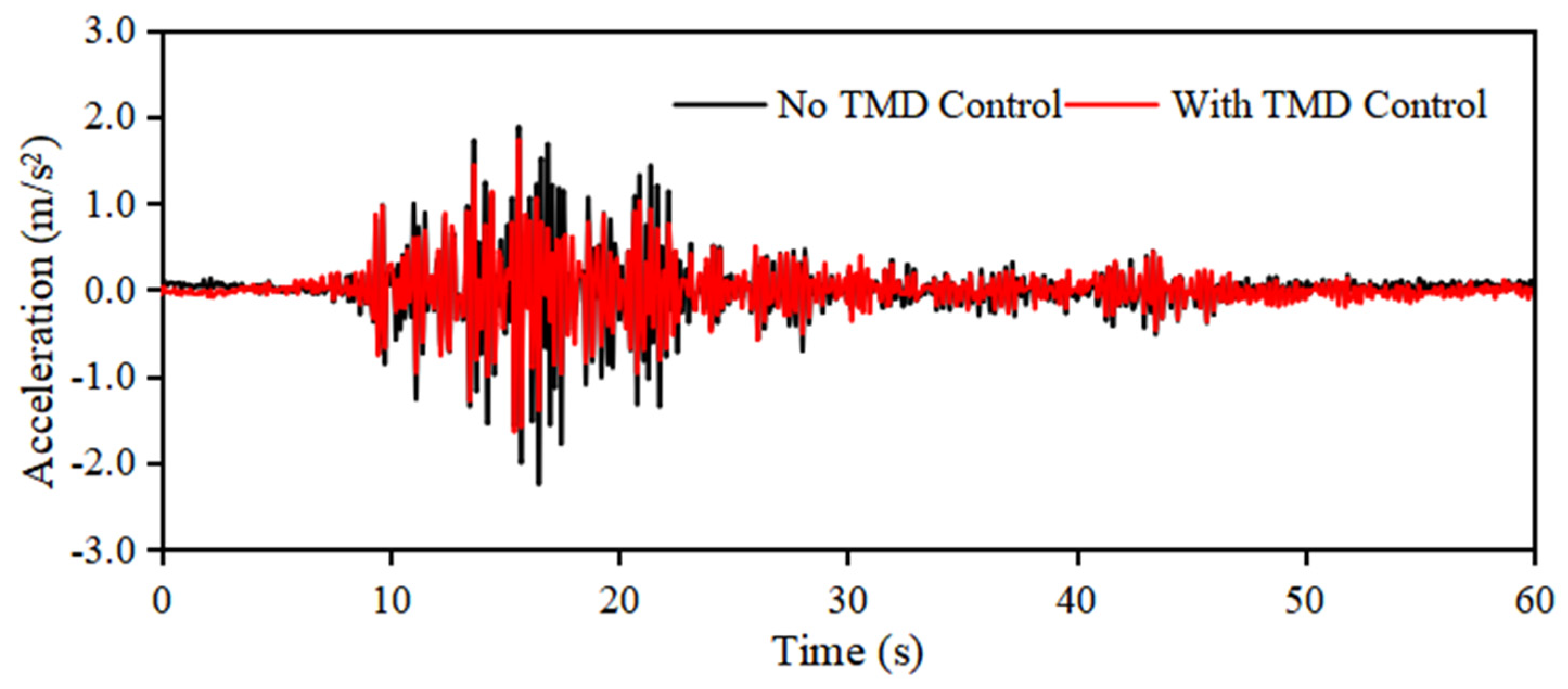
Under the same conditions as in the previous sections for the spherical water tank and TMD, a vibration test was conducted using the Taft NW seismic wave shown in Figure 10 to verify the vibration control performance of the spherical water tank. The effects of different seismic waves were investigated by comparing the measured acceleration response results obtained with those from the previous sections.
Figure 27 shows the acceleration response results obtained from the vibration test conducted in a spherical water tank with a vibration control target frequency of 1.98 Hz, using the Taft NW seismic wave, as discussed in Section 3.1. From Figure 27, it can be observed that the acceleration response for the case using the TMD (red line) was smaller than that for the case without the TMD (black line). This confirms that using the TMD provides vibration control. The standard deviation of the acceleration response in the case without TMD was 0.087 m/s2, whereas that in the case without TMD was 0.049 m/s2, resulting in a vibration control effect of 43.38%.
The results obtained by performing a Fourier transform on the acceleration response measurements, shown in Figure 27, are presented in Figure 28. The Frequency response around a target vibration control frequency of 1.98 Hz is reduced. Furthermore, as shown in Figure 10, the frequency response in the primary frequency range of the Taft NW seismic wave (2–3 Hz) was significantly reduced.
Figure 29 shows the acceleration response results obtained from the excitation test conducted in the spherical water tank with a vibration control target frequency of 4.02 Hz (as discussed in Section 3.2) using the Taft NW seismic wave. From Figure 29, it can be observed that the response in the case using the TMD (red line) is smaller than that in the case without the TMD (black line). Thus, it was confirmed that using a TMD provided a vibration control effect. The standard deviation of the black line graph was 0.396 m/s2, whereas that of the red line graph was 0.307 m/s2, indicating that the vibration control effect achieved using the TMD was 22.42%.
The results obtained by applying the Fourier transform to the acceleration response measurements shown in Figure 27 are shown in Figure 30. It is evident that the frequency response around the vibration control target frequency of 4.02 Hz has significantly decreased.
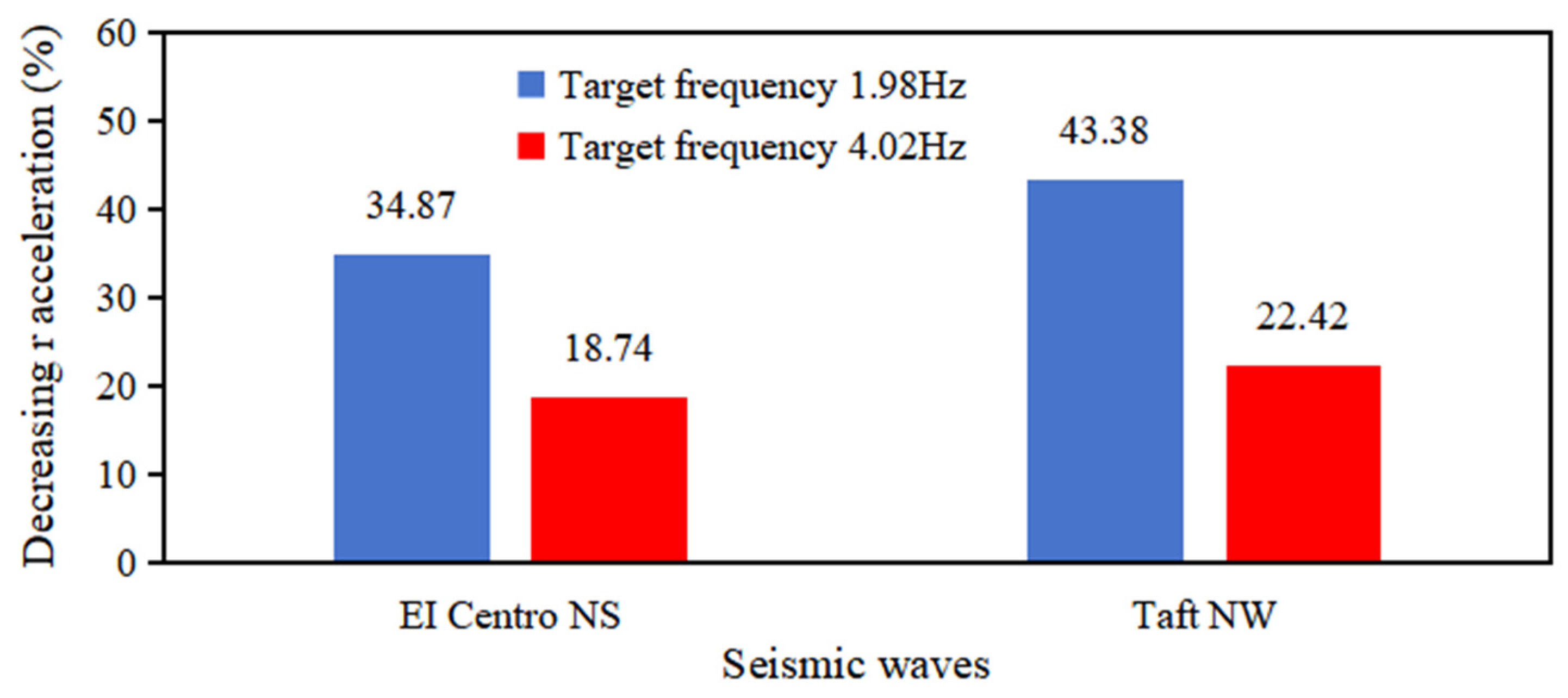
Figure 31 presents the results obtained by conducting vibration tests on the spherical water tank using two types of earthquake waves.
In Figure 31, the vertical axis represents the vibration control effect, expressed as the ratio of the standard deviation of the response acceleration between the spherical water tank and the base. The horizontal axis indicates the type of earthquake wave. The blue bars correspond to the results with a target frequency of 1.98 Hz, whereas the red bars correspond to the results with a target frequency of 4.02 Hz.
Figure 31 shows that, using the same spherical water tank and TMD as the vibration control targets, the vibration control effects under different excitation conditions exhibited similar trends for both the EI Centro NS and Taft NW earthquake waves.
It was confirmed through measurement experiments that if the natural frequency of the TMD was adjusted to match the target frequency determined from the natural frequency of the spherical water tank, vibration control effects could still be achieved even when the external earthquake excitation conditions changed.

4. Conclusions

In this study, the issue of vibration control for spherical water tanks during earthquakes was addressed, and a TMD vibration control device using elastic springs was proposed. After conducting theoretical investigations, an experimental setup consisting of a spherical water tank and a TMD was developed. By varying the configuration conditions of the spherical water tank and the earthquake excitation conditions, detailed examinations were conducted, leading to the following conclusions.
(1)
Vibration control effects can be ensured by matching the target frequency. It was experimentally confirmed that by adjusting the natural frequency of the TMD to match the natural frequency of the spherical water tank, a clear vibration control effect can be obtained.
(2)
It can flexibly respond to changes in the structural conditions of the spherical water tank. Even if the total mass of the spherical water tank or the rigidity of its supporting columns changes, causing fluctuations in its natural frequency, it was shown that sufficient vibration control effect can be maintained by adjusting the TMD.
(3)
As a result of verifying the vibration control effect against different seismic excitation directions, it was confirmed through experimental measurements that even when the excitation comes from directions other than the design direction of the vibration control system, the vibration control effect slightly decreases but still maintains an average effect of more than 15%.
(4)
To verify the vibration control effect against different seismic waves, shaking experiments using the EI Centro NS and Taft NW seismic waves were conducted. The results showed that, regardless of the type of seismic wave, the vibration control effect by the TMD was consistently exhibited at an average level of over 20%. As a future challenge, it is necessary to further examine the versatility of the TMD system, including seismic waves that have occurred around Japan.
(5)
When using the TMD, it was confirmed that the response acceleration is effectively reduced not only around the vibration control target frequency but also within the main frequency ranges of the seismic waves, indicating that the TMD possesses versatile vibration control effectiveness.
Based on the above, the TMD vibration control device using elastic springs proposed in this study has been demonstrated to be effective in reducing vibrations of spherical water tanks during earthquakes, and to be a flexible vibration control method capable of adapting to various changing conditions.
However, as a first step in studying a dedicated TMD vibration control system for spherical water tanks, the tank was approximated using a simplified two-degree-of-freedom vibration model. In future research, more detailed dynamic models are planned to be applied to investigate the vibration behavior of spherical water tanks in greater depth.

Author Contributions

Writing—original draft preparation, J.Z.; writing—review and editing, J.G. and X.Z.; data curation, K.M.; investigation, W.Z.; conceptualization, W.Z. and X.Z.; methodology, J.Z. and X.Z.; validation, J.G. and K.M. All authors have read and agreed to the published version of the manuscript.

Funding

This research received no external funding.

Data Availability Statement

Data available in a publicly accessible repository.

Conflicts of Interest

Jingchao Guan is employee of the International Operations Division NAVIC Co., Ltd. The paper reflects the views of the scientists and not the company.

Abbreviations

The following abbreviations are used in this manuscript:
TMDMultidisciplinary Digital Publishing Institute
FEMfinite element methods

References

  1. Fiore, A.; Demartino, C.; Greco, R.; Rago, C.; Sulpizio, C.; Vanzi, I. Seismic performance of spherical liquid storage tanks: A case study. Int. J. Adv. Struct. Eng. 2018, 10, 121–130. [Google Scholar] [CrossRef]
  2. Shibata, H. Survey Report on Earthquake Damage of Industrial Facilities in the World—Spherical Vessels and Cylindrical Vessels. Seisan Kenkyu 1974, 26, 259–264. [Google Scholar]
  3. Sakai, F. Studies on Seismic Design of Liquid Storage Tanks—Present and Future. J. JSCE 1985, 1985, 1–11. [Google Scholar] [CrossRef] [PubMed]
  4. Yamada, Y.; Iemura, H.; Noda, S.; Shimada, S. Characteristics of Relatively Long-period Ground Motions Estimated form Oil-sloshing in Huge Tanks and Earthquake Records. J. JSCE 1985, 1985, 471–480. [Google Scholar] [CrossRef]
  5. Milovanovic, A.; Sedmak, A. Integrity Assessment of Ammonia Spherical Storage Tank. Procedia Struct. Integr. 2018, 13, 994–999. [Google Scholar] [CrossRef]
  6. Hashimoto, H. Future Trend and Topics of Liquid Sloshing. J. Soc. Mech. Eng. 1986, 89, 512–517. [Google Scholar] [CrossRef]
  7. Karamanos, S.A.; Patkas, L.A.; Platyrrachos, M.A. Sloshing Effects on the Seismic Design of Horizontal-Cylindrical and Spherical Industrial Vessels. J. Press. Vessel Technol. 2006, 128, 328–340. [Google Scholar] [CrossRef]
  8. Hata, R.; Arai, M.; Cheng, L. Nonlinear Sloshing inside a Spherical LNG Tank. In Conference Proceedings, the Japan Society of Naval Architects and Ocean Engineers; Japan Society of Naval Architects and Ocean Engineers: Tokyo, Japan, 2017; Volume 25, pp. 431–434. [Google Scholar] [CrossRef]
  9. Sakada, H.; Sakai, F. Sloshing Effects in Spherical Liquid Storage Tanks. High Press. Inst. Jpn. 1978, 16, 143–151. [Google Scholar] [CrossRef]
  10. Lu, Y.; Sun, J.; Sun, Z.; Cui, L.; Wang, Z. Basic Theory of Simplified Dynamic Model for Spherical Tank Considering Swinging Effect. J. Press. Vessel Technol. 2019, 141, 061202. [Google Scholar] [CrossRef]
  11. Utsumi, M. Vibration analysis of liquid in an asymmetric tank covered by a diaphragm. Mech. Eng. J. 2022, 9, 22-00022. [Google Scholar] [CrossRef]
  12. Utami, S.; Trimulyono, A.; Manik, P. Numerical Simulation of the Effect of Tank Shape on Sloshing Using Smoothed Partical Hydrodynamics. IOP Conf. Ser. Earth Environ. Sci. 2022, 1198, 012002. Available online: https://iopscience.iop.org/article/10.1088/1755-1315/1198/1/012002 (accessed on 1 April 2025). [CrossRef]
  13. Uddin, S.S. Seismic Analysis of Liquid Storage Tanks. Int. J. Adv. Trends Comput. Sci. Eng. 2013, 2, 357–362. [Google Scholar] [CrossRef]
  14. Koyama, K. Earthquake Response Analysis of Spherical Storage Tank. High Press. Inst. Jpn. 1979, 17, 121–129. [Google Scholar] [CrossRef]
  15. Chen, J.; Xian, Q.; Zhang, P. Seismic response analysis and damping method of spherical liquid storage tank. IOP Conf. Ser. Mater. Sci. Eng. 2019, 542, 012006. Available online: https://iopscience.iop.org/article/10.1088/1757-899X/542/1/012006 (accessed on 1 April 2025). [CrossRef]
  16. Singh, R.; Gupta, R.K. Seismic Analysis of Liquid Storage Tank. Trans. SMiRT 2011, 21, 197–201. [Google Scholar]
  17. Hasibuan, P.; Habibi, A.; Panjaitan, A.; Hasan, M.; Saidi, T. Stability Analysis of HSD Tank Against Dynamic Response. E3S Web Conf. 2024, 476, 01032. [Google Scholar] [CrossRef]
  18. Afkar, A.; Camari, M.N.; Paykani, A. Design and analysis of a spherical pressure vessel using finite element method. World J. Model. Simul. 2014, 10, 126–135. Available online: https://www.academia.edu/22301876/Design_and_analysis_of_a_spherical_pressure_vessel_using_finite_element_method (accessed on 1 April 2025).
  19. Malhotra, P.K.; Wenk, T.; Wieland, M. Simple Procedure for Seismic Analysis of Liquid-Storage Tanks. Struct. Eng. Int. 2000, 10, 197–201. [Google Scholar] [CrossRef]
  20. Yang, Z.; Shou, B.; Sun, L.; Wang, J. Earthquake Response Analysis of Spherical Tanks with Seismic Isolation. Procedia Eng. 2011, 14, 1879–1886. [Google Scholar] [CrossRef]
  21. Al-Khafaji, M.S.; Mohammed, A.S.; Salman, M.A. ANSYS-Based Structural Analysis Study of Elevated Spherical Tank Exposed to Earthquake. Eng. Technol. J. 2021, 39, 870–883. [Google Scholar] [CrossRef]
  22. Takiguchi, A. Stress Analysis of Spherical Tank by the Finite Element Method. High Press. Inst. Jpn. 1974, 12, 33–47. [Google Scholar] [CrossRef]
  23. Prakash, K.S.J.; Mastanaiah, T. Industrial Spherical pressure vessel design & analysis using FEA. Int. J. Comput. Eng. Res. 2014, 4, 32–35. Available online: https://www.academia.edu/9363907/Industrial_Spherical_pressure_vessel_design_and_analysis_using_FEA (accessed on 1 April 2025).
  24. Pappa, P.; Vasilikis, D.; Vazouras, P.; Karamanos, S.A. On the Seismic Behaviour and Design of Liquid Storage Tanks. In Proceedings of the Thematic Conference on Computational Methods in Structural Dynamics and Earthquake Engineering, Corfu, Greece, 25–28 May 2011; Available online: https://www.academia.edu/67336598/On_the_seismic_behaviour_and_design_of_liquid_storage_tanks (accessed on 1 April 2025).
  25. Drosos, G.C.; Dimas, A.A.; Karabalis, D.L. Discrete Models for Seismic Analysis of Liquid Storage Tanks of Arbitrary Shape and Fill Height. J. Press. Vessel. Technol. 2008, 130, 041801. [Google Scholar] [CrossRef]
  26. Sezen, H.; Livaoglu, R.; Dogangun, A. Dynamic analysis and seismic performance evaluation of above-ground liquid-containing tanks. Eng. Struct. 2008, 30, 794–803. [Google Scholar] [CrossRef]
  27. Sivy, M.; Musil, M. Design of the Spherical Liquid Storage Tanks for Earthquake Resistance. Ann. Fac. Eng. Hunedoara Int. J. Eng. 2018, 16, 121–126. Available online: https://annals.fih.upt.ro/pdf-full/2018/ANNALS-2018-1-19.pdf (accessed on 1 April 2025).
  28. Asodariya, D.B. Design And Analysis of Spherical Pressure Vessel As Per Manufacturing Aspect. Int. J. Sci. Adv. Res. Technol. (IJSART) 2022, 8, 59–66. Available online: https://ijsart.com/design-and-analysis-of-spherical-pressure-vessel-as-per-manufacturing-aspect-56795 (accessed on 1 April 2025).
  29. Oyelami, A.T.; Olusunle, S.O.O. Spherical Storage Tank Development Through Mathematical Modeling of Constituent Sections. Math. Model. Eng. Probl. 2019, 6, 467–473. [Google Scholar] [CrossRef]
  30. Jaiswa, O.R.; Rai, D.C.; Jain, S.K. Review of Seismic Codes on Liquid Containing Tanks. Earthq. Spectra 2007, 23, 239–260. [Google Scholar] [CrossRef]
  31. Martin, I.; Milos, M. Seismic Resistance of Storage Tanks Containing Liquid in Acc0rdance with Principles of Eurcode 8 Standard. J. Mech. Eng. 2016, 66, 79–88. [Google Scholar] [CrossRef]
  32. Higashi, K. Design of Normal Temperature Spherical Tank, Design of Low Temperature Spherical Tank. High Press. Inst. Jpn. 1998, 36, 31–40. [Google Scholar] [CrossRef]
  33. Wieschollek, M.; Kopp, M.; Hoffmeister, B.; Feldmann, M. Seismic Design of Spherical Liquid Storage Tanks. In Proceedings of the Thematic Conference on Computational Methods in Structural Dynamics and Earthquake Engineering, Corfu, Greece, 26–28 May 2011; Available online: https://congress.cimne.com/eccomas/proceedings/compdyn2011/compdyn2011_full/588.pdf (accessed on 1 April 2025).
  34. Kunieda, M.; Sakurai, H. Application of the Oil Damper to Spherical Tank in Earthquake-Resistant Design. Bull. JSME 1975, 18, 807–812. [Google Scholar] [CrossRef]
  35. Yamashita, K.; Tagawa, K. Development of a Seismic Damper to Spherical Tanks. High Press. Inst. Jpn. 1978, 16, 9–16. [Google Scholar] [CrossRef]
  36. Yamamoto, S.; Nagai, Y.; Kawata, E. An Earthquake Isolating and Vibration Absorbing Equipment for Spherical Tanks. High Press. Inst. Jpn. 1975, 13, 11–19. [Google Scholar] [CrossRef]
  37. Yoshida, Y.; Hamaguchi, M.; Taniguchi, T. Damping Control of Liquid Container on a Carrier with Dual Swing-Type Active Vibration Reducer. Trans. Jpn. Soc. Mech. Eng. 2008, 74, 2031–2037. [Google Scholar] [CrossRef]
  38. Nsieri, E.; Offir, Y.; Shohat, A. Seismic Retrofit of Exiting Spherical Tank using Non-Linear Viscous Dampers. In Proceedings of the Second European Conference on Earthquake Engineering and Seismology, Istanbul, Turkey, 25–29 August 2014; Available online: https://www.researchgate.net/profile/Yaron-Offir/publication/274389647_SEISMIC_RETROFIT_OF_EXITING_SPHERICAL_TANK_USING_NON-LINEAR_VISCOUS_DAMPERS/links/5808be3c08ae07cbaa56e763/SEISMIC-RETROFIT-OF-EXITING-SPHERICAL-TANK-USING-NON-LINEAR-VISCOUS-DAMPERS.pd (accessed on 1 April 2025).
  39. Drosos, J.C.; Tsinopoulos, S.V.; Karabalis, D.L. Seismic retrofit of spherical liquid storage tanks with energy dissipative devices. Soil Dyn. Earthq. Eng. 2019, 119, 158–169. [Google Scholar] [CrossRef]
  40. Shrimali, M.K.; Jangid, R.S. Seismic analysis of base-isolated liquid storage tanks. J. Sound Vib. 2004, 275, 59–75. [Google Scholar] [CrossRef]
  41. Ucar, Y.; Altan, M.F. Optimizing seismic performance: Integrating friction dampers into spherical liquid tanks. J. Sustain. Constr. Mater. Technol. 2024, 9, 294–304. [Google Scholar] [CrossRef]
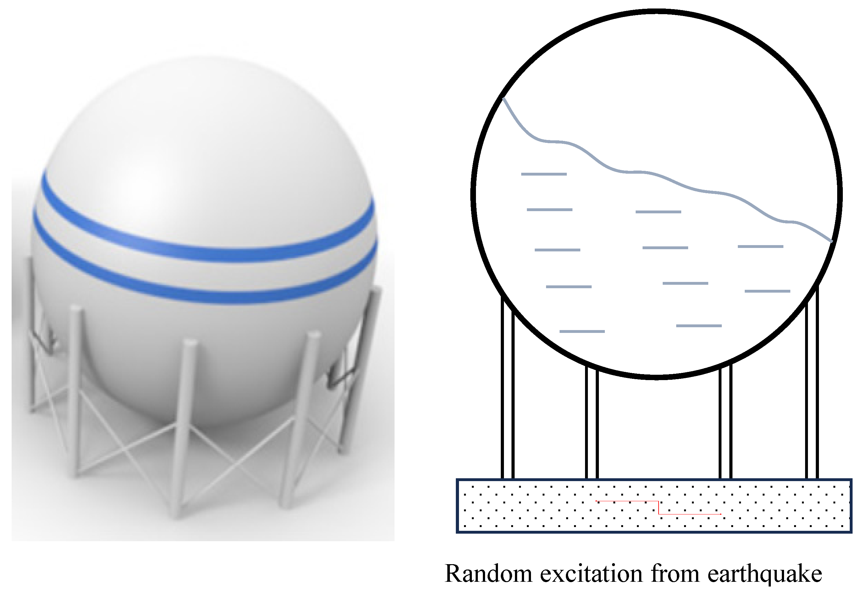
Figure 1. Spherical water tanks in seismic loading environments.
Vibration 08 00041 g001
Figure 2. Vibration response of a spherical water tank subjected to random vibration load.
Vibration 08 00041 g002
Figure 3. Natural vibration analysis model of a spherical water tank.
Vibration 08 00041 g003
Figure 4. Vibration control device for the spherical water tank and the analysis model.
Vibration 08 00041 g004
Figure 5. Device for measuring vibration characteristics of a spherical water tank.
Vibration 08 00041 g005
Figure 6. Verification experiment system and measurement flow chart.
Vibration 08 00041 g006
Figure 7. Photo of the vibration verification experiment system for a spherical water tank.
Vibration 08 00041 g007
Figure 8. Measurement device for the natural frequency of a TMD vibration damper.
Vibration 08 00041 g008
Figure 9. Acceleration distribution and frequency components of the EI Centro NS earthquake.
Vibration 08 00041 g009
Figure 10. Acceleration distribution and frequency components of the Taft NW earthquake.
Vibration 08 00041 g010aVibration 08 00041 g010b
Figure 11. Sweep experiment on a spherical water tank (target frequency 1.98 Hz).
Vibration 08 00041 g011
Figure 12. Sweep experiment on TMD (target frequency 1.98 Hz).
Vibration 08 00041 g012
Figure 13. Sweep experiment on the spherical water tank with TMD (target frequency 1.98 Hz).
Vibration 08 00041 g013
Figure 14. Response acceleration results (EI Centro NS earthquake, target frequency 1.98 Hz).
Vibration 08 00041 g014
Figure 15. Fourier transform result of Figure 14 (EI Centro NS earthquake, target frequency 1.98 Hz).
Vibration 08 00041 g015
Figure 16. Sweep experiment on a spherical water tank (target frequency 4.02 Hz).
Vibration 08 00041 g016
Figure 17. Sweep experiment on TMD (target frequency 4.02 Hz).
Vibration 08 00041 g017
Figure 18. Sweep experiment on the spherical water tank with TMD (target frequency 4.02 Hz).
Vibration 08 00041 g018
Figure 19. Response acceleration results (EI Centro NS earthquake, target frequency 4.02 Hz).
Vibration 08 00041 g019
Figure 20. Fourier transform result of Figure 19 (EI Centro NS earthquake, target frequency 4.02 Hz).
Vibration 08 00041 g020
Figure 21. Experiment of a spherical water tank with different excitation directions.
Vibration 08 00041 g021
Figure 22. Response acceleration results (EI Centro NS earthquake 0°, target frequency 1.98 Hz).
Vibration 08 00041 g022
Figure 23. Response acceleration results (EI Centro NS earthquake 15°, target frequency 1.98 Hz).
Vibration 08 00041 g023
Figure 24. Response acceleration results (EI Centro NS earthquake 30°, target frequency 1.98 Hz).
Vibration 08 00041 g024
Figure 25. Response acceleration results (EI Centro NS earthquake 45°, target frequency 1.98 Hz).
Vibration 08 00041 g025
Figure 26. Vibration control effect on acceleration in different excitation directions.
Vibration 08 00041 g026
Figure 27. Response acceleration results (Taft NW earthquake, target frequency 1.98 Hz).
Vibration 08 00041 g027
Figure 28. Fourier transform result of Figure 27 (EI Centro NS earthquake, target frequency 1.98 Hz).
Vibration 08 00041 g028
Figure 29. Response acceleration results (Taft NW earthquake, target frequency 4.02 Hz).
Vibration 08 00041 g029
Figure 30. Fourier transform result of Figure 29 (Taft NW earthquake, target frequency 4.02 Hz).
Vibration 08 00041 g030
Figure 31. Influence of two types of earthquake waves on vibration control effect.
Vibration 08 00041 g031
Disclaimer/Publisher’s Note: The statements, opinions and data contained in all publications are solely those of the individual author(s) and contributor(s) and not of MDPI and/or the editor(s). MDPI and/or the editor(s) disclaim responsibility for any injury to people or property resulting from any ideas, methods, instructions or products referred to in the content.