Article

Design, Optimization, and Experimental Validation of Dynamic Vibration Absorber for Vibration Suppression in Cantilevered Plate Structures

1
School of Mechanical Engineering and Automation, Beihang University, Beijing 100191, China
2
Jiangxi Research Institute, Beihang University, Nanchang 330096, China
3
State Key Laboratory of High-End Heavy-Load Robots, Foshan 528311, China
4
Guangdong Midea Electric Co., Ltd., Foshan 528311, China
*
Author to whom correspondence should be addressed.
Vibration 2025, 8(3), 40; https://doi.org/10.3390/vibration8030040
Submission received: 22 April 2025 / Revised: 21 June 2025 / Accepted: 2 July 2025 / Published: 8 July 2025

Abstract

Vibration control constitutes a critical consideration in structural design, as excessive oscillations may precipitate fatigue damage, operational instability, and catastrophic failures. Dynamic vibration absorbers (DVAs), serving as passive control devices, demonstrate remarkable efficacy in mitigating structural vibrations across engineering applications. This study systematically investigates the design of DVAs for vibration suppression of a cantilevered plate through integrated theoretical modeling, parameter optimization, structural implementation, and experimental validation. Key methodologies encompass receptance coupling substructure analysis (RCSA) for system dynamics characterization and H∞ optimization for absorber parameter identification. Experimental results reveal 74.2–85.7% vibration amplitude reduction in target mode, validating the proposed design framework. Challenges pertaining to boundary condition uncertainties and manufacturing tolerances are critically discussed, providing insights for practical implementations.

1. Introduction

Vibration suppression in flexible structures constitutes a fundamental requirement for improving operational precision across mechanical and aerospace systems. Dynamic vibration absorbers (DVAs), also commonly referred to as tuned mass dampers (TMDs), operate through targeted energy dissipation mechanisms, effectively mitigating structural vibrations by synchronizing with the host structure’s resonant frequencies. These devices can be classified into three main categories: (1) single-degree-of-freedom (SDOF) systems for specific frequency targeting, (2) multi-degree-of-freedom (MDOF) configurations for broader bandwidth control, and (3) nonlinear variants employing cubic stiffness or other nonlinear elements for enhanced performance. When optimally designed, DVAs demonstrate counter-phase oscillation relative to the host structure, thereby dissipating vibrational energy through viscous damping mechanisms.
The development of effective DVA systems requires three key phases: accurate dynamic characterization of the primary structure, optimization of DVA parameters, and proper physical implementation. For plate structures, this process presents unique challenges due to their distributed mass characteristics and complex boundary conditions. Extensive research has advanced the vibration analysis of plate components. Cho et al. [1] developed a numerical procedure combining lumped mass modeling with free vibration analysis, demonstrating good agreement with experimental measurements in stiffened plate modal frequencies. Damnjanovic et al. [2] pioneered dynamic stiffness matrix formulations that enabled efficient modal analysis of plate assemblies under varied boundary conditions.
Absorber technology has sought to address limitations in classical designs, particularly their sensitivity to detuning and limited operational bandwidth. Pilipchuk [3] and Zevin employed R-function methods to design nonlinear DVAs, offering a mathematical approach to handle geometric constraints and improve design flexibility. Tang and Brennan [4] explored nonlinear absorbers with cubic stiffness, demonstrating enhanced energy dissipation across a wider frequency range. Similarly, Habib et al. [5] investigated quasi-zero stiffness (QZS) isolators, which can achieve superior vibration mitigation with minimal added mass. These nonlinear and passive strategies, while effective, often introduce implementation complexity and require careful tuning.
Parameter optimization represents a critical phase in DVA development. The foundational work of Den Hartog and Ormondroyd [6] established the damped DVA configuration, expanding the effective bandwidth of vibration attenuation. Their work revealed that the frequency response curve of a DVA-coupled main structure intersects two invariant points regardless of the DVA’s damping characteristics. This insight, formalized as H∞ optimization, laid the groundwork for subsequent advancements. Recent studies by Ren, Wong et al., and Krenk have further refined these optimization approaches through innovative adaptations, including damper relocation and root locus analysis [7,8,9,10].
Beyond passive solutions, Tondl and Ruijgrok [11] and Liu et al. [12] studied active and hybrid DVAs capable of adapting to time-varying conditions, improving suppression in real-time but at the cost of increased system complexity and energy consumption. Al-Shudeifat and Butcher [13] provided detailed nonlinear analytical modeling to capture absorber behavior under large-amplitude excitations, highlighting the necessity for advanced models in certain regimes.
The structural implementation of DVAs has evolved significantly from Frahm’s original SDOF concept [14] to contemporary flexure-based designs. Modern DVA configurations range from multiple SDOF systems [15,16] to sophisticated MDOF implementations [17,18,19]. For industrial applications, SDOF DVAs remain predominant due to their structural simplicity and reliability. The implementation of the stiffness module has particularly advanced through flexure-based mechanisms including plate springs and notch-hinge configurations. Recent work by Liu et al. [20,21], Shaw et al. [22], Li et al. [23], Yang et al. [24], and Zhang et al. [25] has demonstrated the superior precision of these approaches compared with traditional spring elements.
This study investigates the design, analysis, and experimental validation of a DVA specifically engineered for vibration suppression in cantilevered plate structures. Firstly, a coupled dynamic model integrating the main structure and DVA system is formulated using RCSA. The FRF of the main structure is derived through FE simulations and serves as the foundational input for subsequent parameter optimization in Section 2. Secondly, the H∞ criterion is employed to identify optimal DVA parameters for minimizing peak displacement amplitudes. In Section 3, the geometric configuration of the DVA is designed, with plate spring dimensions calibrated through iterative computational analysis to align with target natural frequencies. Finite element (FE) simulations further validate the modeling of DVA by benchmarking theoretical predictions of natural frequencies for varying plate spring lengths and FRFs against numerical results. Finally, experimental quantification of vibration suppression efficacy is conducted for both single and multiple DVA configurations (Section 4). The Section 5 synthesizes key findings and outlines practical implications for engineering applications.

2. Theoretical Modeling

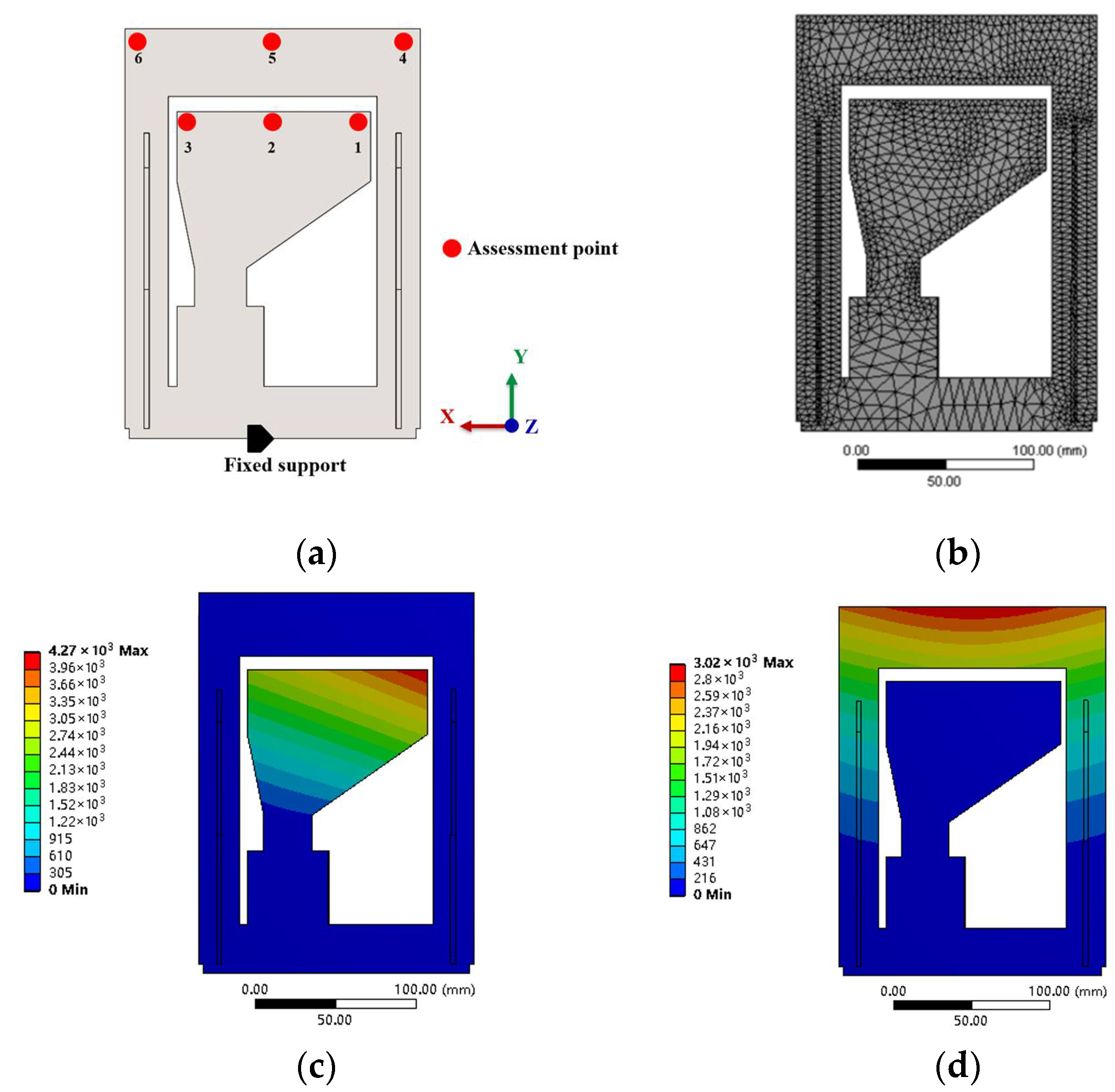
2.1. Modeling and Parametric Design of the Main Structure with DVA

The dynamic equations governing the coupled system in Figure 1a are derived from the interaction between the main structure and the DVA, according to the D’Alembert principle. The dynamic behavior of the main structure is characterized by its FRF, denoted as h11(ω), obtained either through finite element simulations or experimental measurements. Key parameters of the DVA include its mass m1, stiffness k1, and damping coefficient c1. The main structure is subjected to an external harmonic excitation force F0ejωt, with vertical displacements of the main structure and DVA mass defined as X0 and X1, respectively, relative to the equilibrium position (coordinate origin).
The coupled system is conceptually decomposed into two substructures interconnected through a complex spring k* = k + jωc, as depicted in Figure 1b. To synthesize the assembly response, RCSA is employed, leveraging substructure FRFs as referenced in prior studies [26,27].
Due to the fact that the component and assembly coordinates are coincident (x0 = X0, x1 = X1), the displacements of the substructures are expressed as x0 = h00f0 and x1 = h11f1, where h00 and h11 represent the FRFs of the isolated main structure and DVA, respectively. The equilibrium condition requires f0 + f1 = F0, while compatibility of displacements yields
k * ( x 1 x 0 ) = f 1
Substituting X0 and X1 into Equation (1) and applying the equilibrium condition resolves f0:
f 0 = 1 h 11 + h 00 + 1 k * 1 h 00 F 0
The direct and cross FRFs of the coupled system can be derived as
H 00 = X 0 F 0 = h 00 f 0 F 0 = h 00 h 00 h 11 + h 00 + 1 k * 1 h 00
Equation (3) reveals that the modified FRF H00(ω) of the DVA-equipped system depends critically on the term h11(ω) + (k*)−1, which embodies dynamic feedback from the absorber to the main structure. By optimally tuning k1, m1, and c1, this feedback mechanism introduces phase opposition to counteract resonant vibrations. Furthermore, the framework supports iterative integration of additional DVAs into the system, with updated FRFs calculable through recursive application of Equation (3).

2.2. Parameter Design of DVA

This section outlines the parameter design process for the DVA tailored to a cantilevered plate serving as the main structure. The experimental setup, illustrated in Figure 2, includes the main structure with designated assessment points (APs), a fixed support at the lower edge of the main structure for boundary conditions, and a global coordinate system for dynamic characterization.
An FE model of the main structure is first developed to extract its FRF, denoted as h00 in Equation (3), using ANSYS workbench 19.0 with 3D solid elements (Parasolid). Mesh refinement was used and the maximum mesh sizes was constrained (5 mm). Modal analysis reveals the first six natural frequencies of the structure: 101.46 Hz, 121.96 Hz, 221.43 Hz, 289.81 Hz, 520.45 Hz, and 544 Hz. Among these, the bending modes at 101.46 Hz and 121.96 Hz exhibit dominant dynamic contributions, as evidenced by their significant amplitudes shown in Figure 2b,c. Therefore, these two modes are consequently selected as the target frequencies for vibration suppression. Table 1 summarizes the equivalent dynamic parameters identified for the target modes at AP1 and AP5.
The vibration suppression efficacy is assessed through the relative reduction in displacement FRF amplitude of the main structure before and after DVA implementation. Herein, the H∞ optimization criterion is employed, which aims to minimize the peak magnitude of the modified FRF, H00(ω), across the operational frequency range. Specifically, the objective is to identify the optimal absorber parameters (stiffness and damping coefficients) that minimize the worst-case (maximum) vibration amplitude, thereby enhancing robustness under variable excitation conditions. The total mass ratio μ for the dual-DVA configuration is constrained to 3% of the equivalent modal mass m0 (Table 1), a value selected to balance performance enhancement with practical feasibility in industrial applications. For the single-DVA case, the absorber mass is proportionally allocated as μm0/2, ensuring compliance with the total mass limitation while preserving design symmetry. This leads to the following constrained optimization formulation:
Find :   V = k 1 , c 1 T min   f ( V ) = max ω ω min , ω m a x H 00 V , ω V = k 1 , c 1 , k 2 , c 2 ,   m 1 + m 2 = μ m 0 s . t   0 < k 1 , 0 < c 1
where V is the vector of design variables (stiffness and damping coefficients of the two absorbers) and the objective is to minimize the maximum amplitude of the main structure’s frequency response function H00 over the frequency range of interest [ωmin, ωmax]. A mass constraint is imposed such that the total absorber mass satisfies m1 + m2 = μm0, where μ is a specified mass ratio and m0 is the mass of the main structure. The solution yields optimized DVA parameters that effectively reduce the peak response, thereby offer significant vibration attenuation.
Furthermore, numerical optimization is carried out, and the optimal DVA parameters are yielded and listed in Table 2.
The optimized parameters are integrated into Equation (3) to simulate the FRFs of the DVA-equipped system. Figure 3 compares the FRFs at AP1 and AP5 for two configurations: (1) DVA1 suppressing the 101.46 Hz mode and (2) DVA2 targeting the 121.96 Hz mode. In both cases, the original resonance peak splits into two peaks of equal amplitude, which is the characteristic of optimally tuned DVAs. At AP1 (Figure 3a), the theoretical model predicts a 70% amplitude reduction near 101.46 Hz, while DVA2 achieves a 68% reduction at AP5 (Figure 3b). Minor discrepancies between theoretical and simulated results are attributed to idealized boundary conditions in the analytical model, underscoring the importance of FEM validation.
Sensitivity analysis has been conducted with ±5% variation in stiffness or damping and the result shows 1–10% change in suppression performance. This demonstrates the design’s robustness, though precision in fabrication remains important.
Table 3 shows the FRF comparison of the main structure equipped with DVA with optimum parameters; the variation of stiffness of −5% leads to a decrease in the maximum amplitude of 1.35 × 10⁻⁵ m/N, and +5% leads to an increase of 1.82 × 10⁻⁵ m/N at AP1, while the variation of stiffness of −5% leads to a decrease in the maximum amplitude of 9.39 × 10⁻⁶ m/N, and +5% leads to an increase of 1.26 × 10⁻⁵ m/N at AP2. The variation of damping of −5% leads to a decrease in the maximum amplitude of 1.52 × 10⁻⁵ m/N, and +5% leads to an increase of 1.56 × 10⁻⁵ m/N at AP1, while the variation of stiffness of −5% leads to a decrease in the maximum amplitude of 1.05 × 10⁻⁶ m/N, and +5% leads to an increase of 1.08 × 10⁻⁵ m/N at AP2.

3. Structural Design of DVA

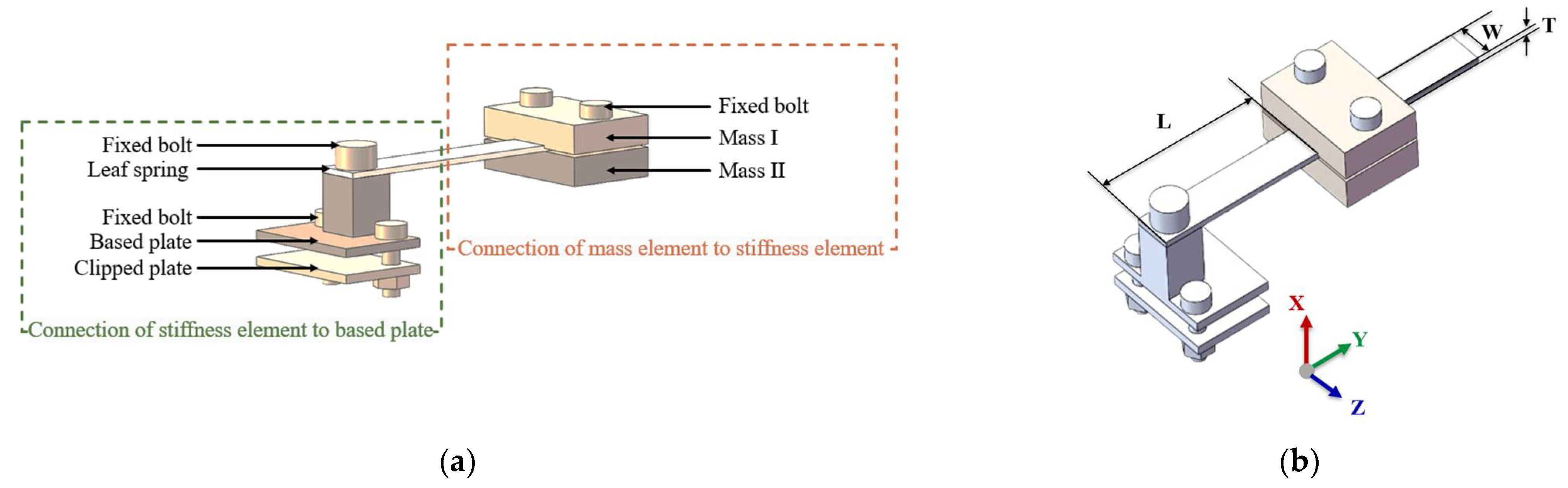
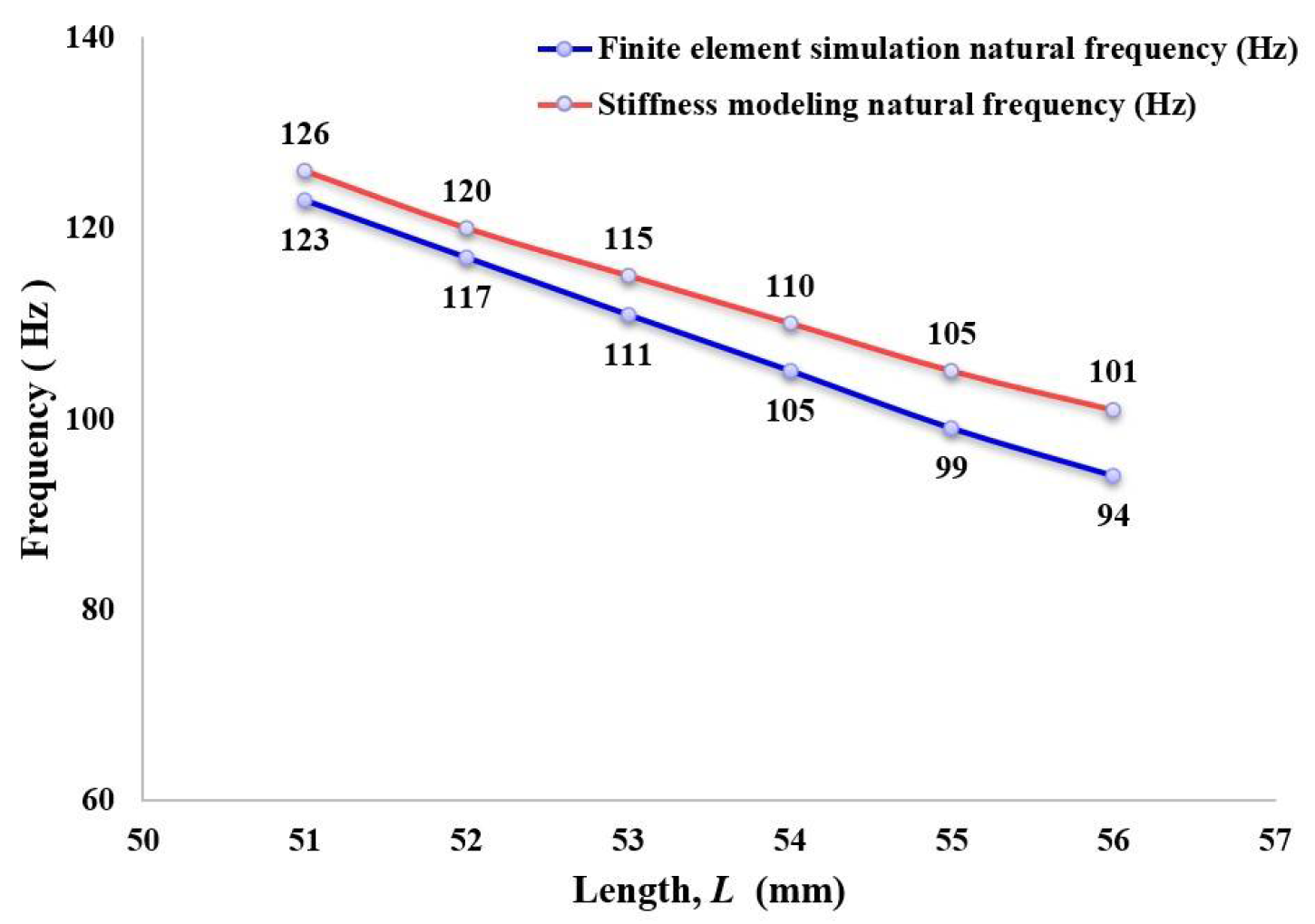
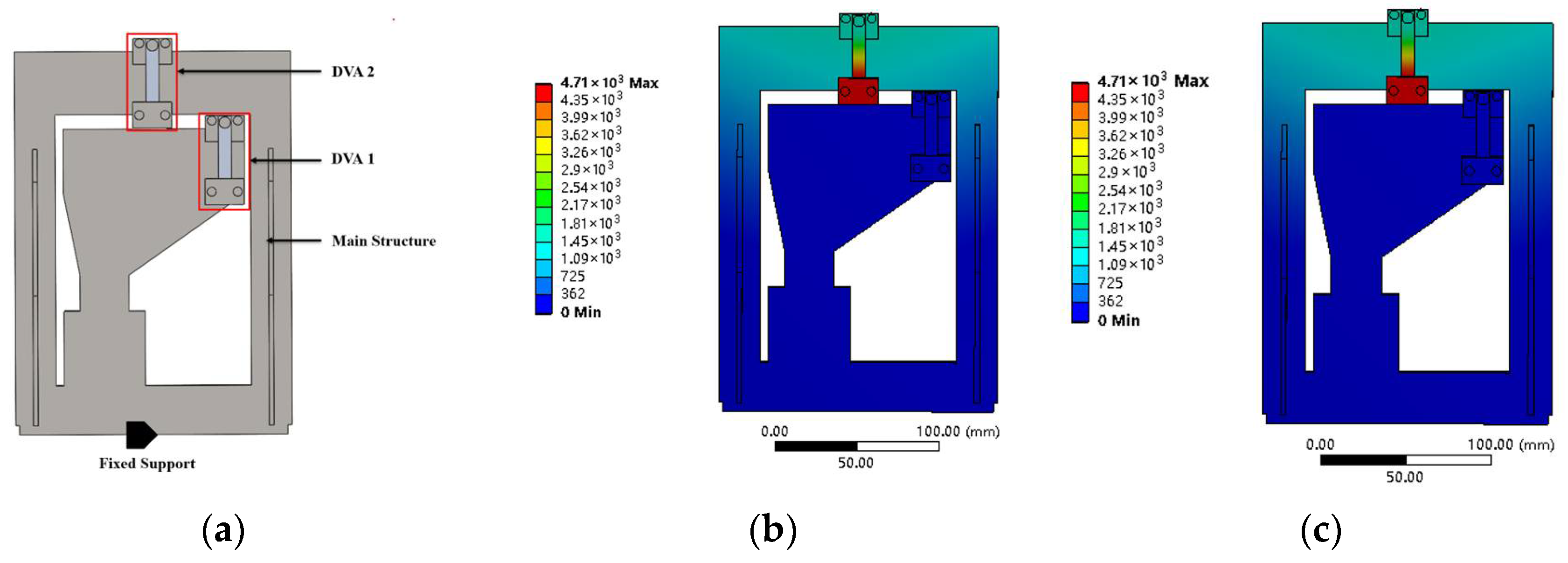
3.1. Geometrical Design and Dynamic Modeling of DVA

The stiffness module, a pivotal component of the DVA, serves dual functions: providing structural support for the absorber mass and facilitating efficient vibrational energy transfer from the main structure. This section elaborates on the geometric and structural design that translates the optimized dynamic parameters (Section 2.2) into a physically realizable DVA configuration.
A SDOF DVA design is adopted, comprising two symmetrically arranged stainless steel (ANSI 304) mass blocks clamped to a cantilevered aluminum alloy (1060) leaf spring, as illustrated in Figure 4a. The plate spring, with a rectangular cross section of 8 mm width and 1 mm thickness, is rigidly anchored to the main structure via a bolted clamping plate. The mass blocks are positioned along the plate spring’s longitudinal axis, enabling tuning of the effective cantilever length (L) to match target natural frequencies. Specifically, DVA1 and DVA2 are tailored for suppressing the 101.46 Hz and 121.96 Hz modes, with mass blocks weighing 0.03 kg.
The coupled dynamics of the main structure and DVA are derived using RCSA, a substructuring technique that synthesizes the frequency response of assembled systems from individual substructure receptances. For the plate spring, modeled as a uniform Euler–Bernoulli beam under clamped–free boundary conditions, the governing equation for transverse displacement y(x, t) is expressed as
ρ A 2 y x ,   t t 2 + E I 4 y x ,   t x 4 = 0
where y(x,t) denotes the transverse displacement of the plate spring. E, G, ρ, A, and I represent Young’s modulus, shear modulus, density, cross-sectional area, and moment of inertia, respectively.
Assuming a harmonic excitation Fsin(ωt) is acted at the free end of the plate spring, the trial function y(x, t) = Y(x)sin(ωt) is employed to eliminate the time dependence, and a fourth-order characteristic equation can be derived, for which the solution takes the form of
Y x = C 1 e λ x + C 2 e λ x + C 3 e λ x + C 4 e λ x
where λ4 = ω2ρA(EI)−1. C1, C2, C3 and C4 are constants that are determined from the boundary conditions as follows. The clamped end (x = 0) satisfies:
y x ,   t | x = 0 = 0 ,   y x ,   t x | x = 0 = 0
while the free end (x = L) yields:
E I 2 y x ,   t x 2 | x = L = 0 , E I x 2 y x ,   t x 2 | x = L = F sin ω t
Combining Equations (6)–(8) and solving C1, C2, C3, and C4 by using Cramer’s rule yields the displacement-force FRF of the plate spring at its free end. F is the magnitude of excitation force
h beam ω = y x ,   ω | x = L F sin ω t = sin λ L cosh λ L cos λ L sinh λ L λ 3 E I 1 + cos λ L cosh λ L
where h beam ω is the FRF of the plate spring.
The DVA’s total receptance hDVA is obtained by coupling the leaf spring’s FRF with the mass block’s inertial dynamics.
h DVA ω = h beam h beam 1 ω 2 m 1 + h beam 1 h beam = h beam 1 ω 2 m 1 h beam
This formulation enables iterative adjustment of geometric parameters (e.g., L) to align the DVA’s natural frequency with target modes, ensuring optimal vibration suppression.

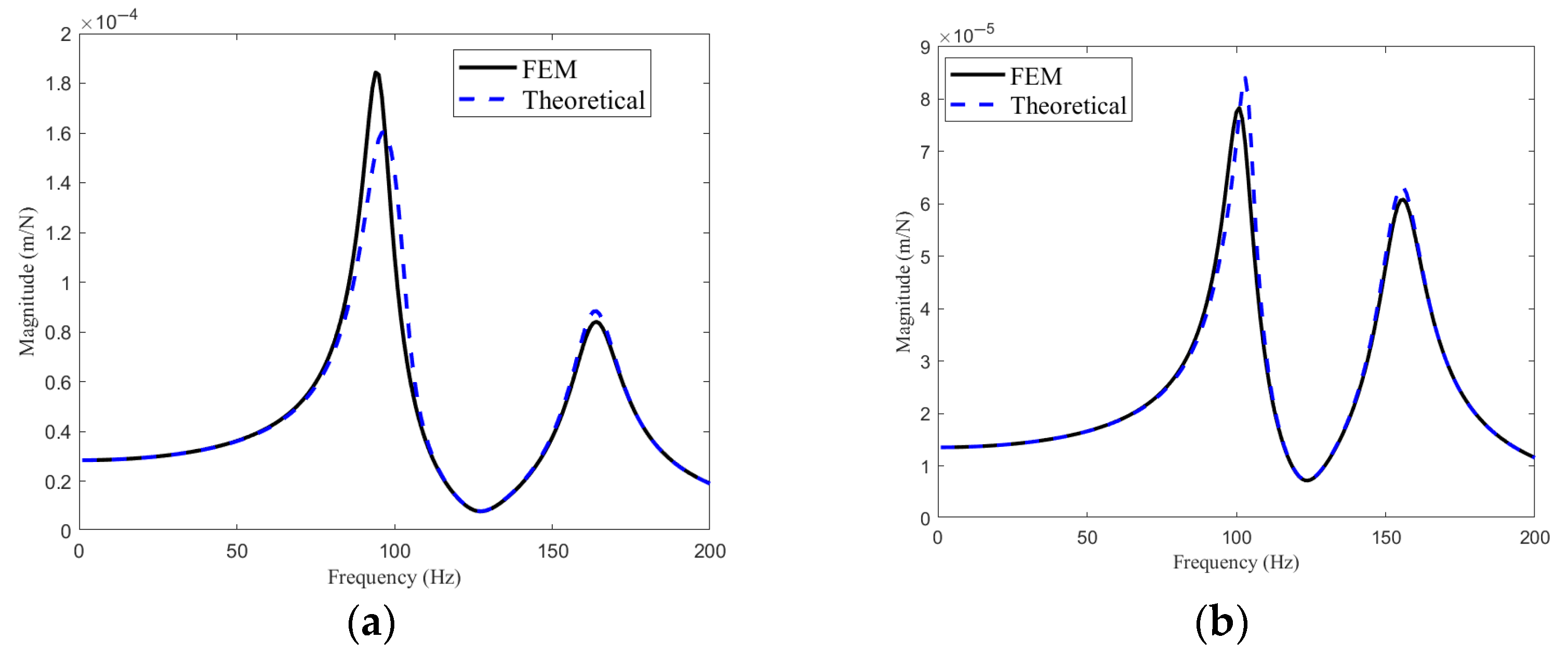
3.2. Simulation and Performance Prediction of DVAs

To validate the theoretical model derived in Section 3.1, finite element (FE) simulations were conducted across a spectrum of leaf spring lengths (51–56 mm). Figure 5 presents a comparative analysis of the natural frequencies predicted by the RCSA model (Equation (10)) against FE results. As the plate spring length increased from 51 mm to 56 mm, a monotonic decline in the simulated natural frequencies was observed, ranging from 123 Hz to 94 Hz. This trend exhibited near-linear proportionality. Notably, the optimized target frequencies of 98.46 Hz and 118.96 Hz (derived from Table 2) fell within the tunable range of the designed DVA, demonstrating the feasibility of frequency matching through geometric adjustments. Moreover, the theoretical predictions aligned closely with FE simulations, with deviations confined to <7.4%. For instance, at a 56 mm spring length, the model predicted 101 Hz versus the simulated 94 Hz, while at 51 mm, the discrepancy narrowed to 126 Hz (predicted) versus 123 Hz (simulated). These minor inconsistencies likely stemmed from idealizations in the analytical model, such as neglecting shear deformation in the Euler–Bernoulli beam formulation. Such deviations underscore the necessity of iterative FE validation to refine geometric parameters for practical implementation. Based on this analysis, optimal spring lengths of 54.3 mm (DVA1) and 51.0 mm (DVA2) were selected to align with the target modes at 101.46 Hz (AP1) and 121.96 Hz (AP5), respectively.
Furthermore, modal simulation of the main structure integrated with both DVAs is performed to assess vibration suppression mechanisms. Figure 6a illustrates the assembly of the main structure with DVAs 1 and 2, and the fixed support for the boundary condition, while Figure 6b,c depict the mode shapes at 98.56 Hz and 103.14 Hz, corresponding to the suppressed target frequencies. Notably, the mass blocks of DVA1 and DVA2 exhibit pronounced out-of-phase motion relative to the main structure, confirming effective energy absorption through counter-phase oscillations. The antiresonance behavior observed in these modes underscores the DVAs’ ability to suppress vibration of the main structure.
Figure 7 compares the theoretical and simulated FRFs of the DVA-equipped system at AP1 and AP5. It should be noted that Cauchy’s damping model is employed in FE simulation, which captures a linear relationship between damping force and velocity and provides a good approximation for metals like steel and aluminum under small-to-moderate vibration amplitudes for characterizing energy dissipation.
It can be observed that both methods capture the characteristic dual-peak response resulting from DVA structure interaction, with natural frequencies aligning within 2% error. For instance, at AP1 (Figure 7a), the theoretical model predicts peaks at 98.5 Hz and 104.2 Hz, closely matching the FEM results of 97.8 Hz and 103.6 Hz. Minor discrepancies in peak amplitudes (<8%) are attributed to identification errors in damping ratios and unmodeled boundary condition flexibility in the physical system, including bolt pre-tension variations which can affect the boundary conditions and stiffness characteristics of the assembled structure, and spring thickness tolerance variation that can alter the stiffness properties of the leaf springs, thereby impacting the dynamic response of the system. These results validate the theoretical framework while underscoring the necessity of FE validation to account for practical complexities.

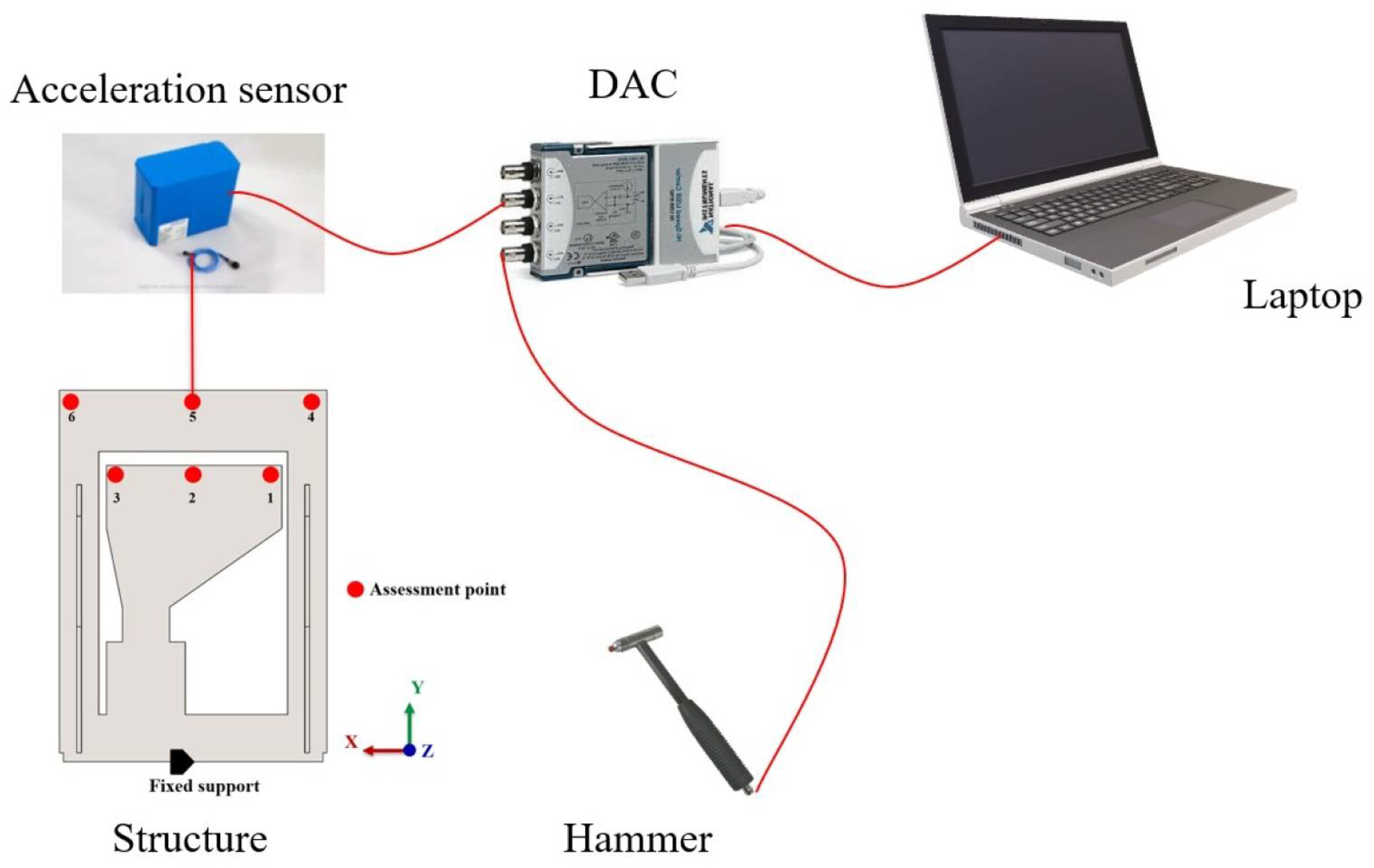
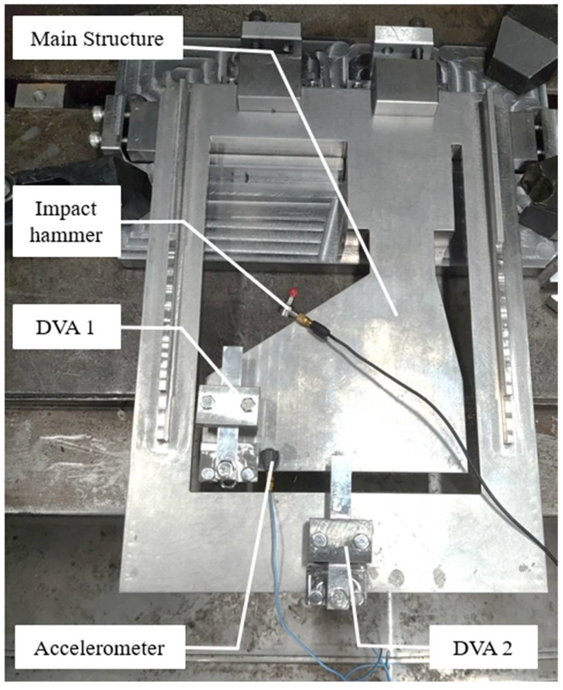
4. Experimental Verification

Hammer tests were conducted to validate the vibration suppression efficacy of the DVA. As illustrated in Figure 8, the main structure is excited at predefined impact points (Figure 2) using an instrumented hammer (PCB086E80, sensitivity: 22.5 mV/N). Acceleration responses are measured at six assessment points (AP1–AP6) via piezoelectric accelerometers (PCB352C22, sensitivity: 10 mV/g), with signal performed using a data acquisition card NI 9234 and processed through CutPro software (v16.0.1396.1). The experimental setup, detailed in Figure 9, ensures rigid boundary conditions by clamping the structure’s base to the platform of a machine tool. To mitigate random errors, three consecutive trials are performed for each test configuration.

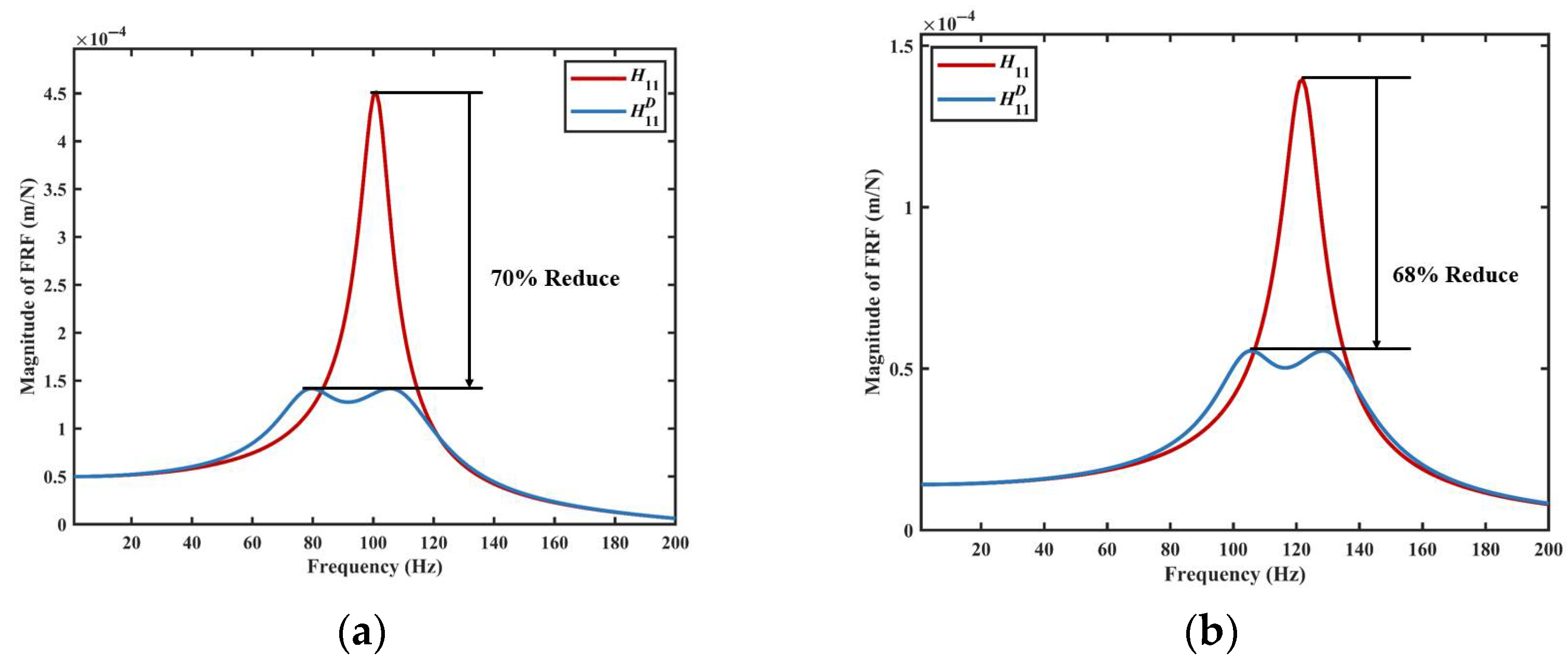
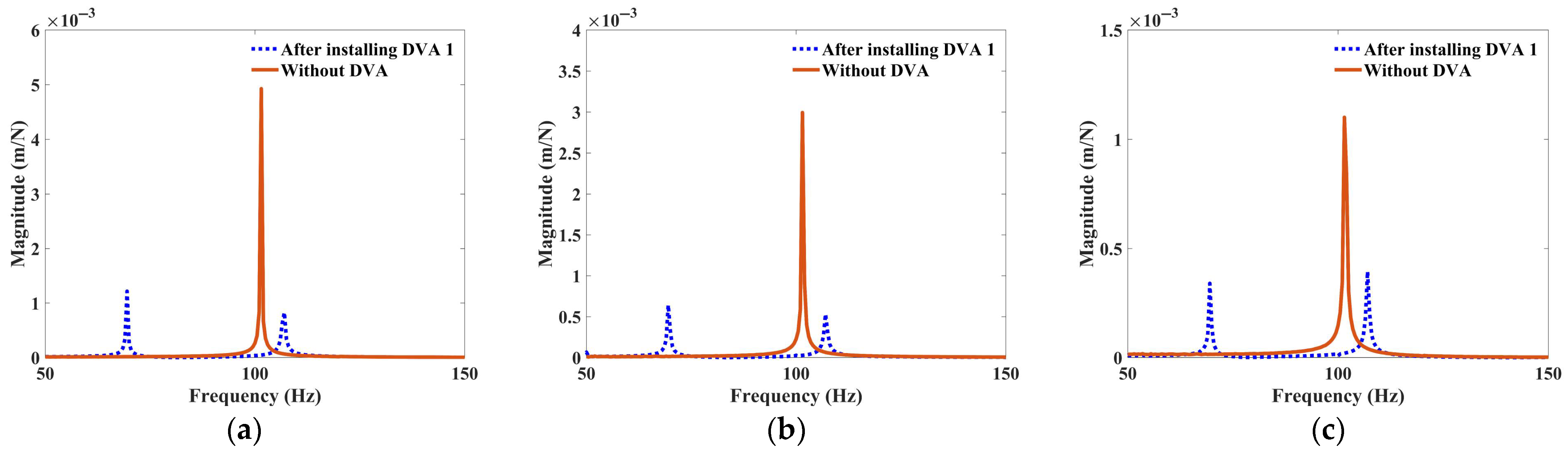
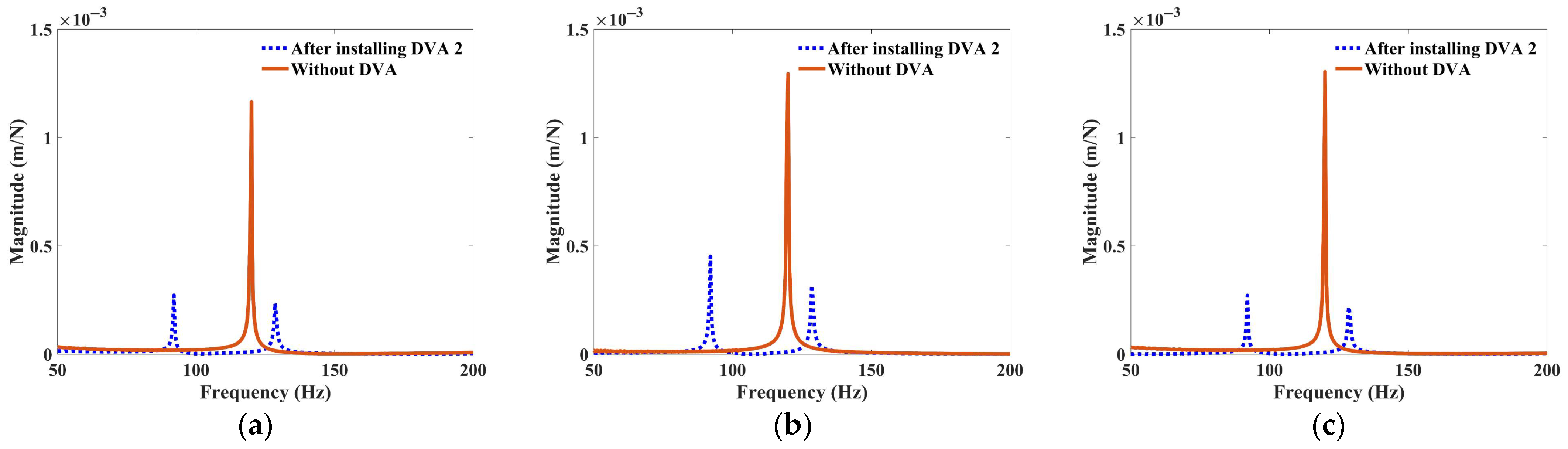
4.1. FRFs of the Main Structure with Single DVA

Figure 10 and Table 4 present the measured FRFs at AP1–AP3 for the main structure with and without DVA1. The absorber significantly attenuates resonance peaks near the target frequency of 101.46 Hz, reducing the amplitude from 4.93 × 10⁻³ m/N (uncontrolled) to 1.22 × 10⁻³ m/N at AP1, corresponding to a 75.3% reduction. Similar trends are observed at AP2 (78.5% reduction) and AP3 (69.1%), confirming DVA1’s effectiveness in suppressing vibration for multiple positions.
Moreover, it is observed that the experimental FRF of the main structure equipped with the DVA, as shown in Figure 10a, exhibits a high degree of consistency with the theoretical predictions presented in Figure 3a (Section 3.2). Specifically, the amplitude reduction observed at assessment point AP1 differs by less than 7%, indicating that the theoretical model reliably captures the dynamic behavior of the system. This close correlation validates the effectiveness of the proposed DVA design and the underlying analytical assumptions, even when applied to real-world structural configurations. Discrepancies arise primarily from unmodeled boundary flexibility and assembly tolerances in the physical system, which slightly alter the effective mass and damping ratios. These findings underscore the necessity of empirical calibration to account for real-world uncertainties.
Furthermore, the performance of DVA2 was experimentally evaluated. Figure 11 and Table 5 summarize the measured FRFs for DVA2, which targets the 121.96 Hz mode. At AP5, the dominant resonance amplitude decreases by 65.1%, from 1.29 × 10⁻³ m/N to 0.45 × 10⁻³ m/N. Notably, AP6 achieves the highest suppression (79.2%), while lower assessment points (AP1–AP3) exhibit modest reductions (<25%), which reflects the spatial dependency of DVA efficacy.

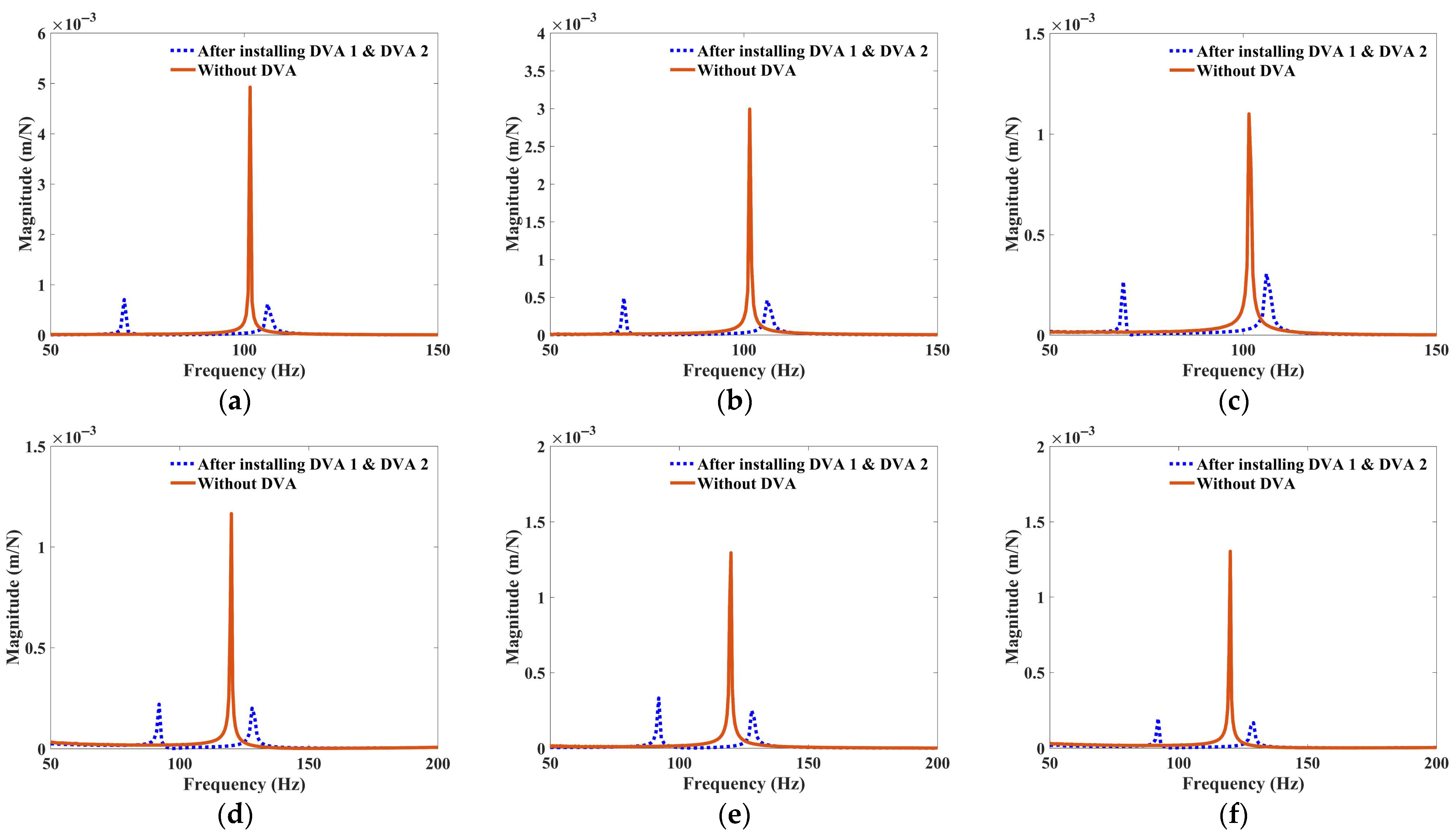
4.2. FRFs of the Main Structure with DVA1 and DVA2

The combined efficacy of DVA1 and DVA2 is evaluated through hammer tests across all six assessment points (AP1–AP6). Figure 12 and Table 6 compare the experimentally measured FRFs of the main structure under three configurations: uncontrolled (no DVA), single-DVA (DVA1 or DVA2), and dual-DVA (combined DVA1 and DVA2). The dual-DVA configuration achieves comprehensive vibration suppression, reducing resonance amplitudes by 74.2–85.7% relative to the uncontrolled system. Spatial variations in attenuation efficacy are observed, with AP1 exhibiting the highest reduction (85.7%) and AP5 the lowest (74.2%). Critically, the dual-DVA system yields a 10.4% improvement in peak attenuation at AP1 compared with the single-DVA configuration, demonstrating constructive superposition of individual absorber dynamics.
From a practical implementation perspective, the dual-DVA system demonstrates superiority over single-DVA configurations, delivering an average 18% relative improvement in vibration suppression across all assessment points. This performance enhancement stems from the synergistic interplay between DVAs, enabling multi-modal energy dissipation through coordinated phase opposition, which is a critical advantage for vibration control in geometrically complex or multi-degree-of-freedom systems. However, the introduction of additional dynamic coupling effects necessitates rigorous optimization of absorber placement and parametric tuning to avoid unintended modal interactions. Future implementations may benefit from model-based optimization algorithms or adaptive tuning mechanisms to balance performance gains against increased design complexity.

5. Conclusions

This research presented and validated a comprehensive approach for designing and optimizing dynamic vibration absorbers (DVAs) aimed at mitigating resonant vibrations in cantilevered plate structures. An integrated framework combining theoretical modeling, finite element simulations, parameter optimization, and experimental validation was developed and demonstrated. The key conclusions that can be drawn from this study are:
(1)
The use of adjustable plate spring stiffness enabled precise frequency tuning while preserving mechanical simplicity.
(2)
Optimized DVA configurations achieved less than 4.7% deviation between theoretical and measured natural frequencies.
(3)
Experimental results confirmed significant vibration suppression, with amplitude reductions of 70–85% at target resonant frequencies.
(4)
Dual-DVA arrangements outperformed single-DVA setups, improving peak attenuation by up to 10.4% and reducing modal energy by up to 85.7% at critical assessment points.
These results confirm the effectiveness of the proposed design methodology and highlight the potential of distributed DVAs in complex vibration-sensitive systems. Future work will explore the development of adaptive, multi-DOF, and nonlinear DVA architectures capable of targeting multiple resonant modes under time-varying operating conditions, further bridging the gap between passive and intelligent vibration control strategies. Bolt loosening and leaf spring fatigue under cyclic loading could also be considered for long-term use durability. Meanwhile, nonlinear dynamic models for large deflections could be incorporated. Repeated vibrations may cause joint loosening and reduce system effectiveness, while sustained cyclic stresses could lead to spring fatigue and stiffness degradation. Mitigation strategies such as improved fastening methods and fatigue-resistant materials should be considered in future designs.

Author Contributions

Formal analysis, L.Y. and W.M.; Funding acquisition, W.M. and W.W.; Project administration, Y.Y. and W.W.; Software, L.Y.; Supervision, Y.Y. and W.M.; Writing—original draft, L.Y. and W.M.; Writing—review and editing, Y.Y. All authors have read and agreed to the published version of the manuscript.

Funding

This work is supported by the National Natural Science Foundation of China (Grant No. 52205005), Jiangxi Provincial Natural Science Foundation (Grant No. 20224BAB214046), State Key Laboratory of High-end Heavy-load Robots (Open Fund Project No. HHR2024010212), and Fundamental Research Funds for the Central Universities (JKF-20240515, JKF-20240570).

Data Availability Statement

Data are contained within the article.

Conflicts of Interest

Wenjing Wu is an employee of Guangdong Midea Electric Co., Ltd. The paper reflects the views of the scientists and not the company.

References

  1. Cho, D.S.; Kim, B.H.; Kim, J.-H.; Choi, T.M.; Vladimir, N. Free vibration analysis of stiffened panels with lumped mass and stiffness attachments. Ocean. Eng. 2016, 124, 84–93. [Google Scholar] [CrossRef]
  2. Damnjanović, E.; Marjanović, M.; Nefovska-Danilović, M. Free vibration analysis of stiffened and cracked laminated composite plate assemblies using shear-deformable dynamic stiffness elements. Compos. Struct. 2017, 180, 723–740. [Google Scholar] [CrossRef]
  3. Pellicano, F.; Mastroddi, F. Nonlinear Dynamics of a Beam on Elastic Foundation. Nonlinear Dyn. 1997, 14, 335–355. [Google Scholar] [CrossRef]
  4. Abolfathi, A.; Brennan, M.J.; Waters, T.P.; Tang, B. On the Effects of Mistuning a Force-Excited System Containing a Quasi-Zero-Stiffness Vibration Isolator. J. Vib. Acoust. 2015, 137, 044502. [Google Scholar] [CrossRef]
  5. Habib, H.S.; Tawfiq, S.S.; Sa’id, W.K. A microprocessor-based time optimal control for reduction of torsional vibration. J. Sound Vib. 1995, 180, 17–28. [Google Scholar] [CrossRef]
  6. Ormondroyd, J.; Den Hartog, J.P. The Theory of the Dynamic Vibration Absorber. Trans. Am. Soc. Mech. Eng. 1928, 49–50, 021007. [Google Scholar] [CrossRef]
  7. Asami, T.; Nishihara, O.; Baz, A.M. Analytical Solutions to H∞ and H2 Optimization of Dynamic Vibration Absorbers Attached to Damped Linear Systems. J. Vib. Acoust. 2002, 124, 284–295. [Google Scholar] [CrossRef]
  8. Cheung, Y.L.; Wong, W.O. H∞ and H2 optimizations of a dynamic vibration absorber for suppressing vibrations in plates. J. Sound Vib. 2009, 320, 29–42. [Google Scholar] [CrossRef]
  9. Liu, Y.; Cheng, L. Exact H∞ optimization of dynamic vibration absorbers: Univariate-polynomial-based algorithm and operability analysis. Appl. Math. Model. 2025, 139, 115812. [Google Scholar] [CrossRef]
  10. Wang, J.; Zhang, Y.; Looi, D.T. Analytical H∞ and H2 optimization for negative-stiffness inerter-based systems. Int. J. Mech. Sci. 2023, 249, 108261. [Google Scholar] [CrossRef]
  11. Benton, M. Devices for Damping Mechanical Vibrations, a Bibliography; Naval Research Laboratory: Washington, DC, USA, 1956. [Google Scholar]
  12. Liu, D.; Luo, M.; Zhang, Z.; Hu, Y.; Zhang, D. Operational modal analysis based dynamic parameters identification in milling of thin-walled workpiece. Mech. Syst. Signal Process. 2022, 167, 108469. [Google Scholar] [CrossRef]
  13. Askes, H.; Lombardo, M.; Nguyen, D.C.D. Homogenisation of periodic lattices with lumped and distributed mass: Beam models, continualisation and stabilisation. Int. J. Solids Struct. 2024, 302, 112988. [Google Scholar] [CrossRef]
  14. Frahm, H. Device for Damping Vibrations of Bodies. U.S. Patent US989958A, 18 April 1928. Available online: https://patents.google.com/patent/US989958A/en (accessed on 17 February 2025).
  15. Love, J.S.; Tait, M.J. Estimating the added effective damping of SDOF systems incorporating multiple dynamic vibration absorbers with nonlinear damping. Eng. Struct. 2017, 130, 154–161. [Google Scholar] [CrossRef]
  16. Ma, W.; Yang, Y.; Yu, J. General routine of suppressing single vibration mode by multi-DOF tuned mass damper: Application of three-DOF. Mech. Syst. Signal Process. 2019, 121, 77–96. [Google Scholar] [CrossRef]
  17. Raze, G.; Kerschen, G. H ∞ optimization of multiple tuned mass dampers for multimodal vibration control. Comput. Struct. 2021, 248, 106485. [Google Scholar] [CrossRef]
  18. Ma, W.; Yu, J.; Yang, Y. Graphical Design Methodology of Multi-Degrees-of-Freedom Tuned Mass Damper for Suppressing Multiple Modes. J. Vib. Acoust. 2021, 143, 011008. [Google Scholar] [CrossRef]
  19. Qin, Y.; Tan, J.J.; Hornikx, M. Application of multiple dynamic vibration absorbers in reducing low-frequency vibration of a floor-like lightweight joist structure: Comparison of experimental and computational results. Appl. Acoust. 2023, 211, 109437. [Google Scholar] [CrossRef]
  20. Liu, M.; Zhang, X.; Fatikow, S. Design and analysis of a multi-notched flexure hinge for compliant mechanisms. Precis. Eng. 2017, 48, 292–304. [Google Scholar] [CrossRef]
  21. Zhang, L.; Liu, M.; Hong, L.; Li, C.; Zhou, Z. Design and Optimization of an FBG Accelerometer Based on Single-Notch Circular Flexure Hinge for Medium-Frequency Vibration Measurement. IEEE Sensors J. 2022, 22, 20303–20311. [Google Scholar] [CrossRef]
  22. Shaw, A.D.; Neild, S.A.; Wagg, D.J.; Weaver, P.M.; Carrella, A. A nonlinear spring mechanism incorporating a bistable composite plate for vibration isolation. J. Sound Vib. 2013, 332, 6265–6275. [Google Scholar] [CrossRef]
  23. Li, W.; Wang, Z.; Brennan, M.J.; Yang, T. Design and optimization of a two-degrees-of-freedom single-sided vibro-impact nonlinear energy sink for transient vibration suppression of a thin plate. J. Sound Vib. 2024, 587, 118512. [Google Scholar] [CrossRef]
  24. Yang, Q.; Zhong, R.; Wang, Q.; Qin, B. Dynamic analysis and optimization of functionally graded graphene platelet stiffened plate carrying multiple vibration absorbers. Ocean. Eng. 2025, 316, 119909. [Google Scholar] [CrossRef]
  25. Zhang, X.; Cui, L.; Qi, H.; Wang, H.; Lin, L. Seismic fragility analysis of traditional Chinese timber structures based on a simplified lumped mass model considering joint damage. Structures 2024, 70, 107863. [Google Scholar] [CrossRef]
  26. Kumar, U.V.; Schmitz, T.L. Spindle dynamics identification for Receptance Coupling Substructure Analysis. Precis. Eng. 2012, 36, 435–443. [Google Scholar] [CrossRef]
  27. Schmitz, T.; Betters, E.; Budak, E.; Yüksel, E.; Park, S.; Altintas, Y. Review and status of tool tip frequency response function prediction using receptance coupling. Precis. Eng. 2023, 79, 60–77. [Google Scholar] [CrossRef]
Figure 1. Schematic of DVA-coupled structure. (a) Mechanical diagram of structure with DVA; (b) The coupling subsystems.
Vibration 08 00040 g001
Figure 2. Structural layout and deformation results of the main structure. (a) Layout of assessment points and fixed boundary condition; (b) Mesh model; (c) Target mode 1; (d) Target mode 2 (color contours show relative deformation magnitude).
Vibration 08 00040 g002
Figure 3. FRF of the main structure equipped with DVA. (a) The FRF at AP1; (b) The FRF at AP5.
Vibration 08 00040 g003
Figure 4. The structure design of the DVA. (a) The configuration of the DVA; (b) Dimensions of the DVA.
Vibration 08 00040 g004
Figure 5. Comparison of natural frequencies obtained by FE simulation and stiffness modeling for different lengths.
Vibration 08 00040 g005
Figure 6. Structural layout and modal analysis: (a) Schematic of the main structure with DVAs showing fixed boundary conditions (clamped edges); (b) Mode shape 1 with DVA1 and 2 ω1 = 98.563 Hz, with color contours indicating relative deformation magnitude; (c) Mode shape 2 with DVAs 1 and 2, ω2 = 103.14 Hz with color contours showing relative deformation magnitude.
Vibration 08 00040 g006
Figure 7. FRF comparison of the main structure with DVA between FEA and Theoretical analysis. (a) FRF at AP1; (b) FRF at AP5.
Vibration 08 00040 g007
Figure 8. The test system of the validation experiment.
Vibration 08 00040 g008
Figure 9. The experimental setup of the hammer test.
Vibration 08 00040 g009
Figure 10. Measured FRFs of the main structure without and with DVA1 at multiple assessment points. (a) FRFs at AP1; (b) FRFs at AP2; (c) FRFs at AP3.
Vibration 08 00040 g010
Figure 11. Measured FRFs of the main structure without and with DVA2 at multiple assessment points. (a) FRFs at AP4; (b) FRFs at AP5; (c) FRFs at AP6.
Vibration 08 00040 g011
Figure 12. Measured FRFs of the main structure without and with DVA1 and DVA2 at multiple assessment points. (a) FRFs at AP1; (b) FRFs at AP2; (c) FRFs at AP3; (d) FRFs at AP4; (e) FRFs at AP5; (f) FRFs at AP6.
Vibration 08 00040 g012
Table 1. Dynamics parameters of the main structure.
Natural Frequency (ω0)Number of APsEquivalent Mass (m0)Equivalent Stiffness (k0)Damping Ratio (ξ0)
101.46 Hz11.97 Kg766,076.12 N/m0.05%
121.96 Hz51.97 Kg1,115,701.89 N/m0.06%
Table 2. Optimal DVA parameters.
k1c1
DVA122,461.12 N/m7.39 Ns/m
DVA232,712.04 N/m8.92 Ns/m
Table 3. FRF of the main structure with DVA under ±5% variation in stiffness or damping.
Stiffness (−5%)Stiffness (+5%)Damping (−5%)Damping (+5%)
AP1, maximum amplitude1.35 × 10−5 (78%)1.82 × 10⁻⁵ (70.78%)1.52 × 10⁻⁵ (75.73%)1.56 × 10⁻⁵ (75.1%)
AP1, maximum amplitude9.39 × 10−6 (78.25%)1.26 × 10⁻⁵ (70.77%)1.05 × 10⁻⁵ (75.72%)1.08 × 10⁻⁵ (75.05%)
Table 4. Comparative results of vibration reduction in the main structure before and after the attachment of DVA 1.
Assessment PointFreq. (Hz)Max. Amplitude (×10−3 m/N)Vibration Reduction
Without DVAWith DVA
1101.1.464.931.2275.3%
22.990.6478.5%
31.100.3469.1%
Table 5. Comparative results of vibration reduction in the main structure before and after the attachment of DVA2.
Assessment PointFreq. (Hz)Max. Amplitude (×10−3m/N)Vibration Reduction
Without DVAWith DVA
4121.961.170.2776.7%
51.290.4565.1%
61.300.2779.2%
Table 6. Comparative results of vibration reduction in the main structure before and after the attachment of DVA1 and DVA2 together.
Assessment PointFreq. (Hz)Max. Amplitude (×10−3m/N)Vibration Reduction
Without DVAWith DVA
1101.54.930.7185.68%
22.990.4983.51%
31.100.2775.69%
4120.01.170.2281.01%
51.290.3374.23%
61.300.2084.72%
Disclaimer/Publisher’s Note: The statements, opinions and data contained in all publications are solely those of the individual author(s) and contributor(s) and not of MDPI and/or the editor(s). MDPI and/or the editor(s) disclaim responsibility for any injury to people or property resulting from any ideas, methods, instructions or products referred to in the content.

