1. Introduction
Efficient production technologies for offshore oil fields have attracted the attention of research engineers for many years. Particular emphasis has been placed on investigating drilling and production risers because of their importance in transferring the oil from offshore structures to oil handling and processing facilities. The dynamic and hydrodynamic behavior of these risers can become challenging because of their slender design. These challenges stem from, one the one hand, their susceptibility to elastic instabilities [
1,
2] when used for handling oil at high flow speeds. On the other hand, these slender risers can experience excessive vortex-induced vibrations (
VIVs) when subjected to high-velocity underwater currents [
3]. The mitigation of both the elastic instabilities and the
VIVs has been the focus of extensive and innovative investigations using both passive [
4] and active means [
5,
6].
An excellent review of the state of the art of passive and active control devices for the vortex-induced vibration of circular cylinders is given by Zhao [
7]. In his review, the effectiveness of different types of passive control devices are reviewed and discussed. Also, the characteristics of various active control approaches are reviewed in a comparative manner, highlighting their merits and shortcomings.
With more emphasis on the hydrodynamics of the vortex-induced vibration of marine risers, Liu et al. [
8] presented a detailed review of the relevant theoretical and experimental efforts. Particular emphasis was placed on the use of various passive and active control devices. Other novel approaches are adopted to passively control the vortex-induced vibration of risers using grooved and spanwise strips, as reported by Hu et al. [
5].
Also, How et al. [
9] presented a boundary control approach to actively control the vibration of flexible marine risers. More recently, vortex-induced vibrations were mitigated by Chen et al. [
10] using deep reinforcement learning (DRL)-based active flow control (AFC), which employs arrays of jet actuators.
In 2022, a hybrid active- and passive-flow-induced vibration control was proposed by Hasheminejad and Masoumi [
11] using a wake-mounted smart piezoelectric bimorph splitter plate.
The interaction between the internal flow on the vortex-induced vibration of marine risers was studied extensively by Leng et al. [
12] for different support methods.
Finally, Zhang et al. [
13] presented a passive control approach to mitigate the instability and response of a top-tensioned Riser subject to parametric excitations.
In this paper, a radically different approach is adopted, whereby conventional risers are provided with an optimally placed and designed array of periodic inserts that simultaneously reinforce the conventional riser in order to enhance its elastic instability threshold to internal flows and generate unique wave propagation filtering characteristics that can trap the vortex shedding excitation to mitigate their effects.
Therefore, this paper is organized into seven sections. In
Section 1, a brief introduction is presented. The concept of the periodic riser is introduced in
Section 2. The theoretical analysis of the dynamics of this class of risers is developed in
Section 3 using the theory of finite elements. The dispersion and bandgap characteristics of the periodic risers are presented in
Section 4 and
Section 5. Both the stability thresholds and bandgap characteristics of the periodic risers are outlined in
Section 6 and compared with the corresponding characteristics of conventional risers.
Section 7 summarizes the conclusions and the potential for its future extensions.
2. Concept of Periodic Marine Risers
In view of the brief introduction about risers, it is evident that there is a need to simultaneously control the vibration and instabilities of these risers due to the combined effects of conveying internal fluids (at a certain speed,
Ui) and the effect of the external flow (at a certain speed,
Ue), which generates vortex-induced vibrations (
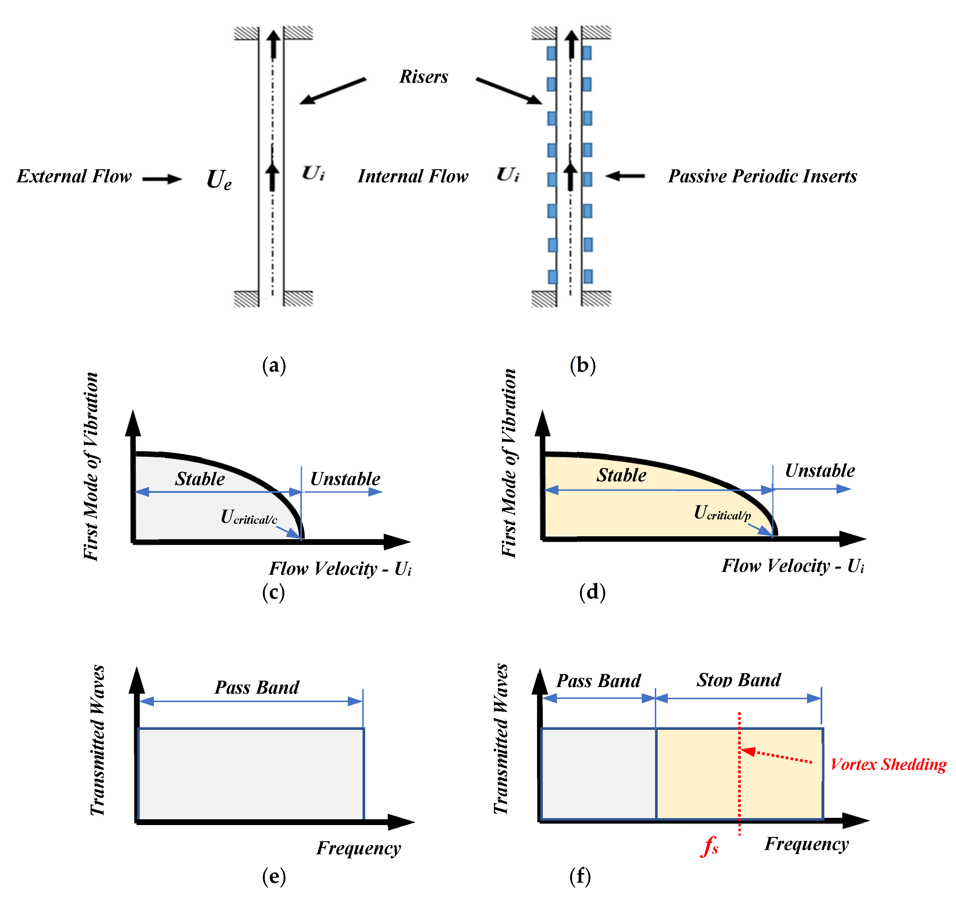
VIVs). In this paper, the emphasis is placed on replacing conventional risers, as shown in
Figure 1a, with periodic risers, as shown in
Figure 1b. In their operation, the periodic risers rely on the optimal placement and design of periodic inserts that reinforce the riser, on the hand, to enhance its elastic instability threshold to internal flows and, on the other hand, to introduce stop/pass band characteristics that can trap the vortex shedding frequencies to mitigate their effects.
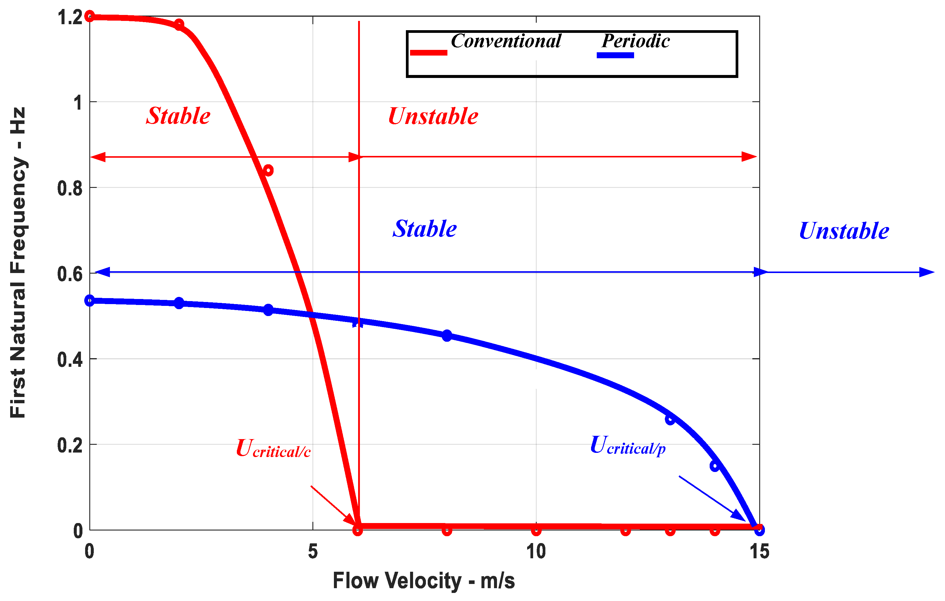
Figure 1c displays the continuous decay of the frequency of the first mode of vibration of the conventional riser as the flow velocity increases. When this frequency approaches zero, the riser will buckle at a critical flow velocity of
Ucritical/c. In the case of the periodic riser, the incipient of buckling is delayed to a higher critical flow velocity of
Ucritical/p because of the reinforcement effect generated by the periodic inserts.
Figure 1e shows that conventional risers will allow all the vibration to pass along the riser over the entire frequency range. In contrast, the periodic riser will act as a low-pass filter that only allows the low-frequency excitation to pass through, while it completely blocks the propagation of the high-frequency excitation, as shown in
Figure 1f.
In this manner, the periodic riser can be designed so that the location and spectral width of its stop band can trap all the possible shedding frequencies (
fs) that the riser may be subjected, to as shown in
Figure 1f. Accordingly, the undesirable effects of the vortex-induced vibrations can be mitigated.
It is important to note that it is envisioned that the realization of the periodic riser concept will not be difficult, as the risers are made of pipe sections that are screwed together, and the inserts will be located at the junctions between the different pipe sections.
3. Finite Element Model of the Riser
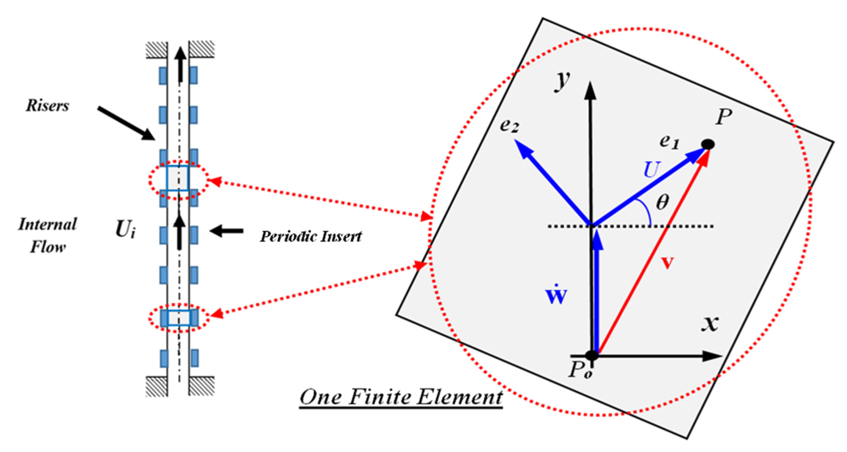
The finite element of the marine riser is developed in this section by extracting the potential and kinetic energies of a representative element of the riser (plain or with an insert), as shown in
Figure 2.
where
EI = flexural rigidity, and
w,xx = curvature.
The total kinetic energy T consists of the riser’s structural kinetic energy Ts and the kinetic energy of the fluid inside the riser Tf, so that the following applies:
- a.
Structural Kinetic Energy:
where
M = mass of riser/unit length,
L = element length,
w = transverse deflection, and
x = the
x coordinate along the element. Also,
Ir = mass moment Inertia of the periodic rings/unit length.
- b.
Fluid Kinetic Energy:
The kinetic energy is determined by considering the position vector
R for a fluid particle
P, as shown in
Figure 2, as follows:
The velocity
v is determined from
where
U is the flow velocity.
Accordingly, the fluid kinetic energy
Tf can be determined from
where
ρ = fluid density, and
A = riser’s internal diameter.
Then, the total kinetic energy
T is given by
As
, Equation (5) reduces to
- c.
The Finite Element Equations:
Using the classical cubic shape function, the deflection
w is written in terms of the nodal deflection vector as follows:
where [
N] denotes the interpolation matrix, and {Δ
e} denotes the vector of nodal displacements =
, with
denoting transverse and angular deflections of the
ith node of a finite element bounded by the nodes
i and
j.
Then, the element stiffness [Ke], mass [Me], and gyroscopic [Ge] matrices can be extracted as follows:
Mass and Gyroscopic Matrices:
where
,
, and
.
Then, the equations of motion are given by
4. Dispersion Characteristics of the Periodic Risers
The periodic riser shown in
Figure 1 is divided into identical periodic cells.
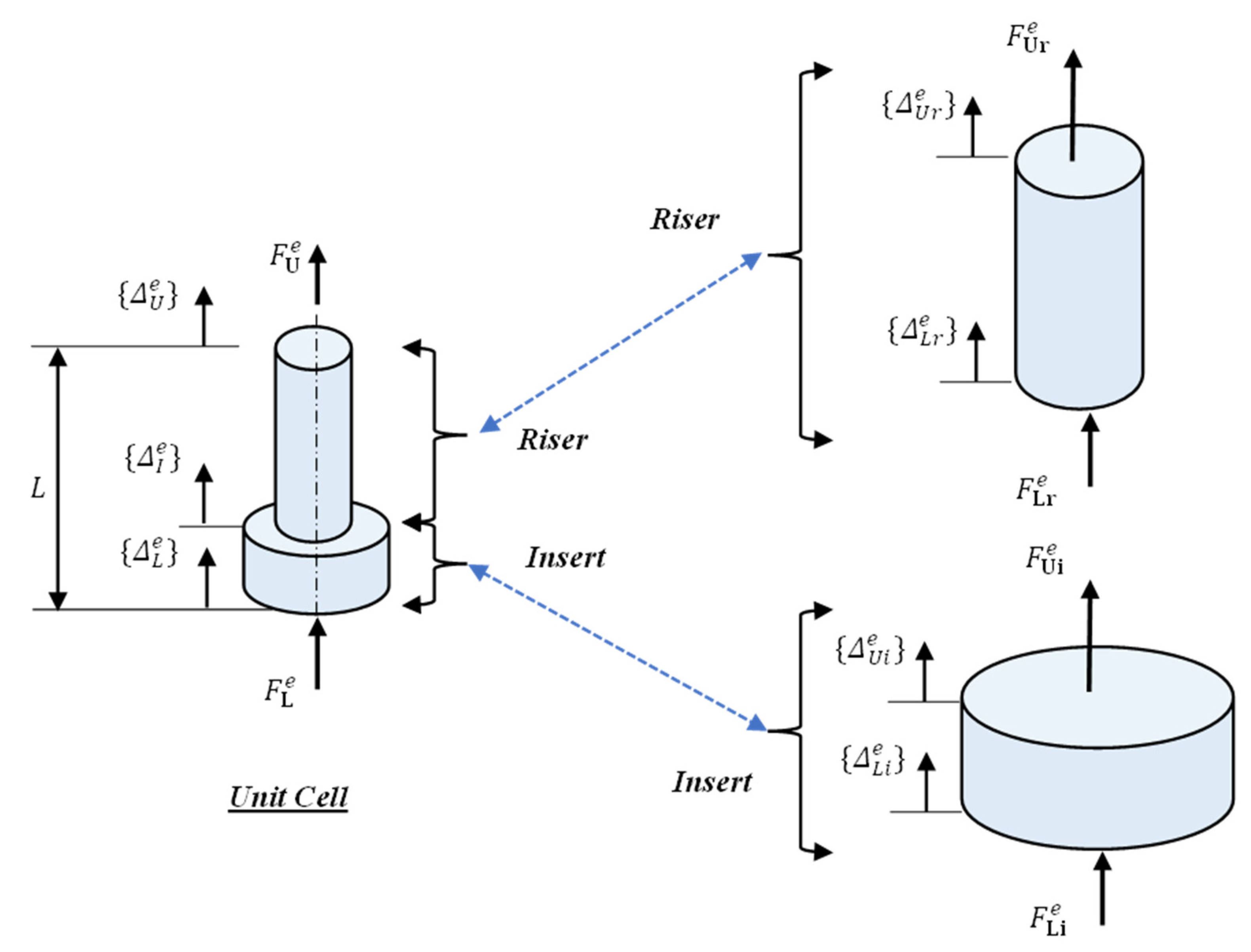
Figure 3 shows the degrees of freedom of a passive unit cell. For a given unit cell, the vector
defines the nodal deflection vector described in Equation (7), and the vector
defines the generalized forcing function acting on the unit cell, such as external loads and moments.
Accordingly, the nodal deflection vector of a unit cell
is defined as
where
,
, and
denote the upper, internal, and lower deflection vectors.
Equation (11) is condensed to support Bloch wave propagation [
14,
15,
16,
17]. Hence, the displacements at the boundaries are related as follows:
where
and
denote the wave number and the length of the unit cell, respectively.
Hence,
is defined as an independent nodal deflection vector so that
The deflection vectors
and
are related as follows:
where
is a transformation matrix described as
Substituting Equations (14) and (15) into the equation of motion, Equation (10), the finite element model for a gyroscopic unit cell reduces to
where
,
,
, and
.
Equation (16) can be represented in a state-space form as recommended by Meirovitch [
18] as follows:
where
.
We assume that the state-space solution takes the following form:
where
and
.
Then, Equation (18) yields the following eigenvalue problem:
Equation (19) can be rewritten as follows:
where
.
Equating the real and imaginary coefficients in Equation (20) yields
Equations (21) and (22) can be rewritten in compact and standard eigenvalue problem form so that
where
.
Note that all the entries of the matrix are functions of the dimensionless wave number . Therefore, the eigenvalues of the matrix can be determined for different values of the wave number .
The eigenvalues λ
s are given by
The dispersion characteristics of the gyroscopic unit cell of the passive periodic riser can be constructed by plotting the resonant frequency
against the wave number
. The resulting dispersion curves can also define the zones of stop and pass bands of the periodic riser, which are analyzed separately using the “
transfer matrix” approach as outlined in
Section 5.
5. Bandgap Characteristics of the Periodic Risers
The bandgap characteristics of the periodic riser are determined using the “
transfer matrix” approach [
14]. First, the equation of motion (Equation (10)) is rewritten for each component of the unit cell (the riser element and the insert element) for sinusoidal excitation at a frequency ω so that
Hence, we consider the configuration of the riser–insert assembly shown in
Figure 4.
Equation (25) reduces to
where
are the partitioned matrices of the dynamic stiffness matrix of the riser element:
.
Equation (26) is rearranged as follows:
In a compact form, Equation (27) becomes
where
denotes the output state vector at the upper end of the riser, the input state vector at the lower end of the riser, and the transfer matrix describing the energy transfer from the bottom to the top ends of the riser.
Equation (25) reduces to
where
are the partitioned matrices of the dynamic stiffness matrix of the insert element:
.
Equation (29) is rearranged as follows:
In a compact form, Equation (30) becomes
where
denotes the output state vector at the upper end of the insert, the input state vector at the lower end of the inert, and the “
transfer matrix” describing the energy transfer from the bottom to the top ends of the insert.
Combining Equations (28) and (31) gives
Equation (32) describes the energy flow from the lower end of the insert to the top end of the riser. Accordingly, the total transfer matrix Tt governs such an energy transfer.
To identify the nature of the energy flow between these two ends, Equation (32) is rewritten as follows:
where
λ is the eigenvalue of the total transfer matrix
Tt. Hence, if
λ is equal to 1, the energy is transferred completely between the two ends, suggesting a “
Pass Band”; otherwise, the energy flow will be disrupted, indicating a “
Stop Band”.
6. Performance Characteristics of the Periodic Risers: Critical Flow Velocities (Stability Threshold) and Bandgap Characteristics
In this section, the predictions of the finite element model, developed in
Section 3, as well as the associated dispersion and bandgap characteristics, presented in
Section 4 and
Section 5, are generated for a periodic riser that has the physical and geometrical characteristics listed in
Table 1.
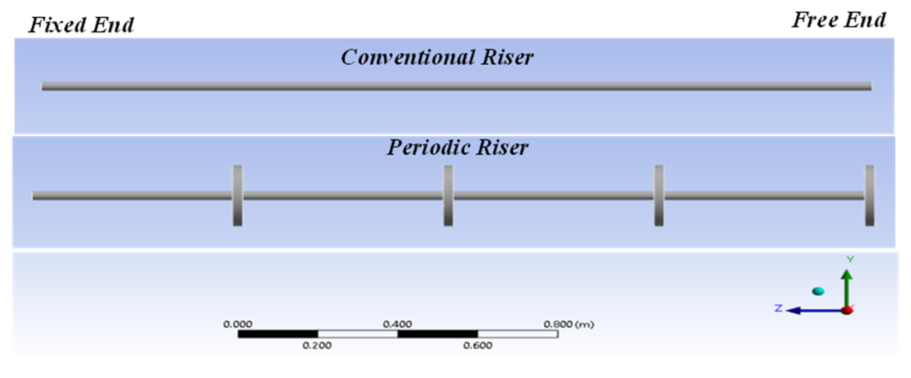
The theoretical predictions are compared with those of the commercial finite element package (
ANSYS).
Figure 5 displays the
ANSYS finite element models of the conventional and periodic risers.
- a.
Critical Flow Velocities (Stability Threshold)
Figure 6 displays a comparison between the critical flow velocities, i.e., the stability thresholds of the conventional and the periodic risers. The displayed characteristics indicate that the periodic riser has a stability zone extending to a critical velocity of 15 m/s, compared to 5.8 m/s for the conventional riser. Such a tripling extension of the stability boundary makes the periodic riser more effective in transporting larger oil flows than its conventional counterpart. Such a critical performance metric translates into enhanced productivity of the oil handling capabilities.
- b.
Frequency Response Characteristics
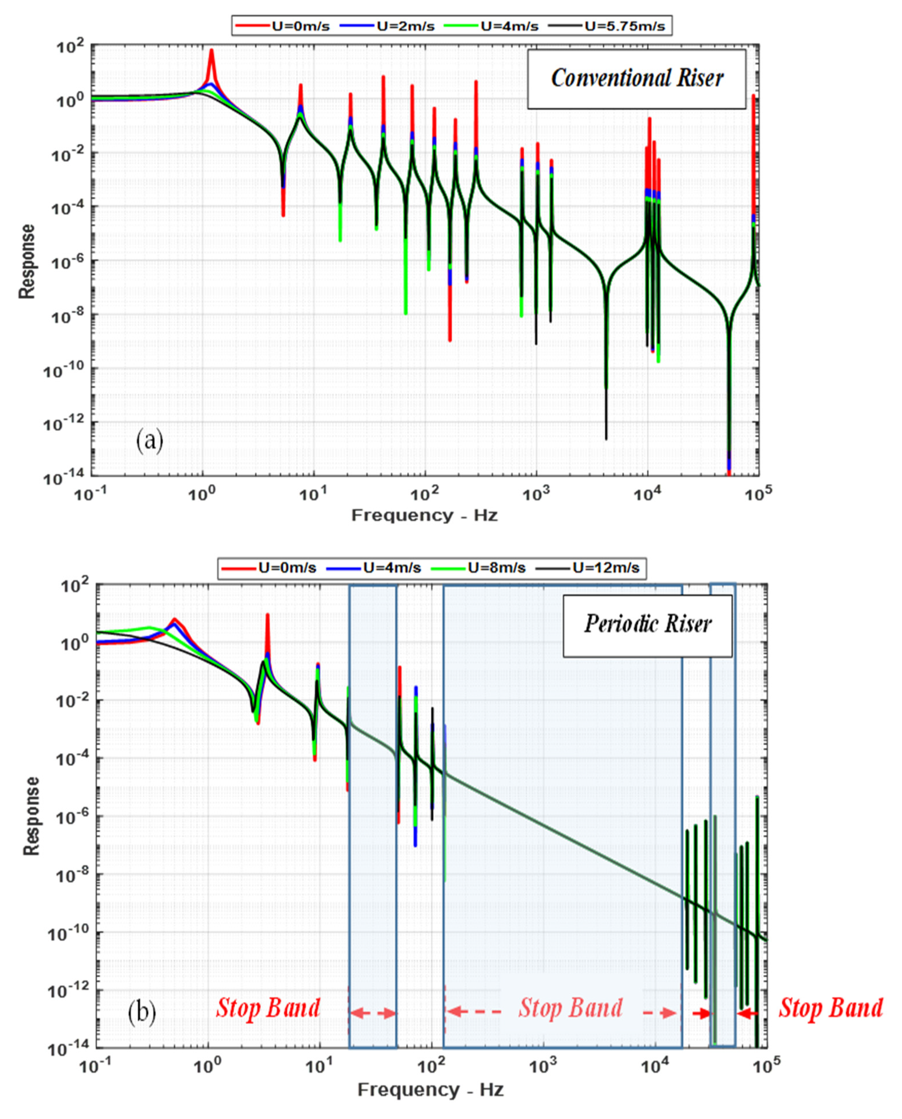
Figure 7a,b display comparisons between the frequency characteristics of the conventional and periodic risers, as predicted by the theoretical model from
Section 3, for different flow velocities that are below the instability threshold.
First,
Figure 7 clearly indicates that increasing the flow velocity results in reducing the resonant frequency of the first mode while not significantly affecting other higher modes. Second, and most importantly,
Figure 7a indicates that the frequency spectrum of the conventional riser is closely packed with resonant modes of vibration. However, the modes of the periodic riser are not closely packed but are separated by zones of stop bands, resulting from the unique filtering characteristics of this class of risers, as indicated in
Figure 7b. The presence of these zones is attributed to the bandgap characteristics of the periodic risers that can be predicted using the Bloch wave theory described in
Section 4.
- c.
Comparison Between the Theoretical Frequency Response Characteristics and those of ANSYS
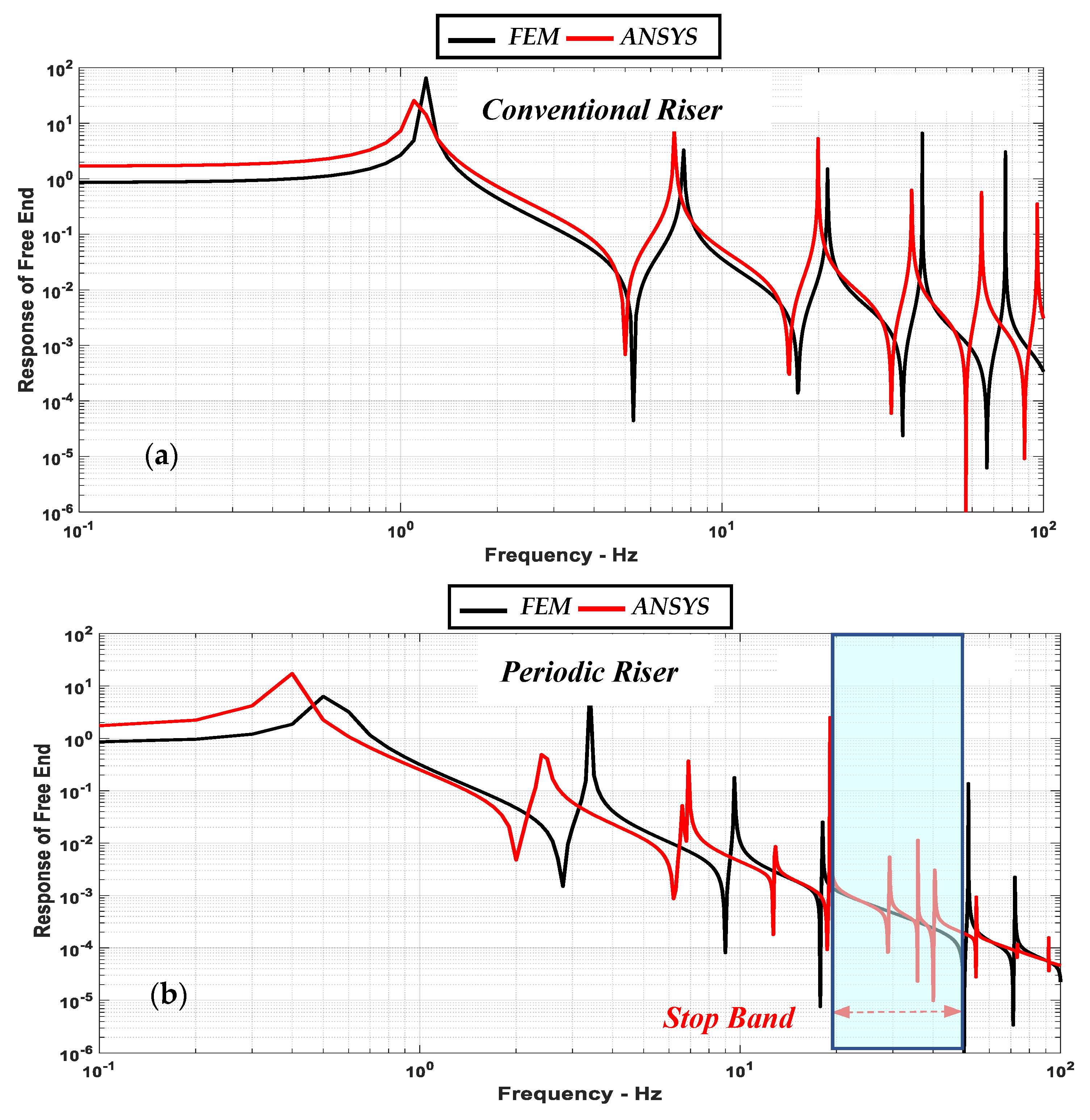
Figure 8a,b display comparisons between the frequency characteristics of the conventional and periodic risers, as predicted by the theoretical model from
Section 3, and
ANSYS. A reasonable agreement is evident between the two models, especially for the conventional riser.
Table 2 and
Table 3 list comparisons between the modal frequencies of the conventional and periodic risers as predicted by theoretical
FEM and
ANSYS. A reasonable agreement is evident between the two approaches. Note that the differences between the theoretical
FEM and
ANSYS are small for the lower modes and become larger for higher-order modes.
- d.
Dispersion Characteristics of the Periodic Riser
Figure 9a,b display the dispersion characteristics of the periodic riser at flow velocities of 0 m/s and 14 m/s, respectively. The displayed results indicate that the dispersion characteristics remain nearly unaffected over this wide range of flow velocities. Furthermore,
Figure 7 indicates the presence of two stop bands between 20 and 50 Hz and between 110 and 2 × 10
4 Hz. These bands match the stop bands displayed in the frequency response characteristics of
Figure 7 and
Figure 8.
- e.
Bandgap Characteristics of the Periodic Riser
The analysis of the bandgap characteristics presented in
Section 5 is used to extract the eigenvalues λ of the total transfer matrix
Tt of the periodic riser. Also, the eigenvalues are expressed as follows:
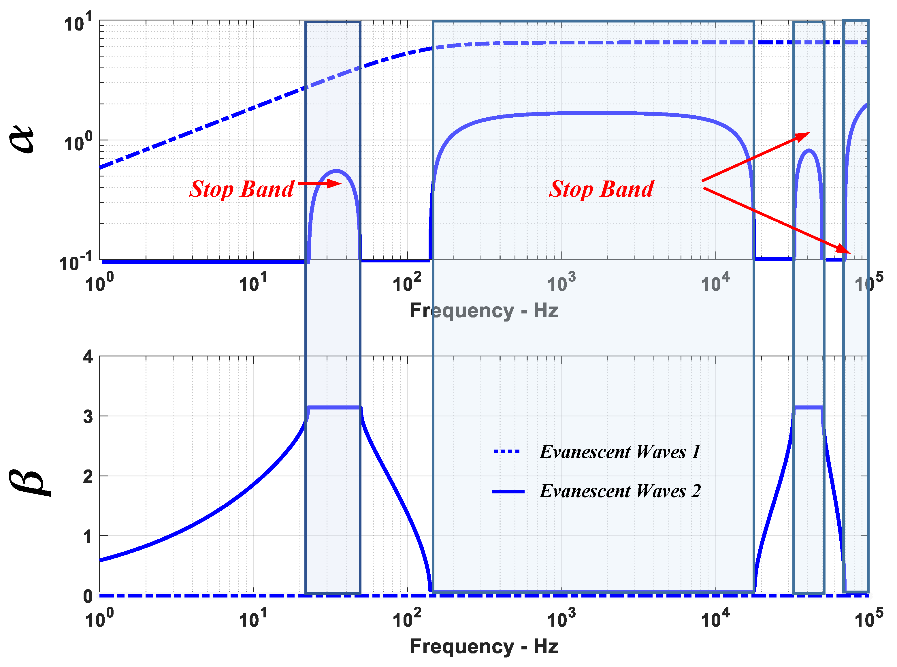
where
μ is defined as the “
Propagation Constant”, which is a complex number whose real part (
α) represents the “
logarithmic decay” parameter of the state vector, and its imaginary part (
β) defines the “
phase shift” parameter, which quantifies the difference between the adjacent cells.
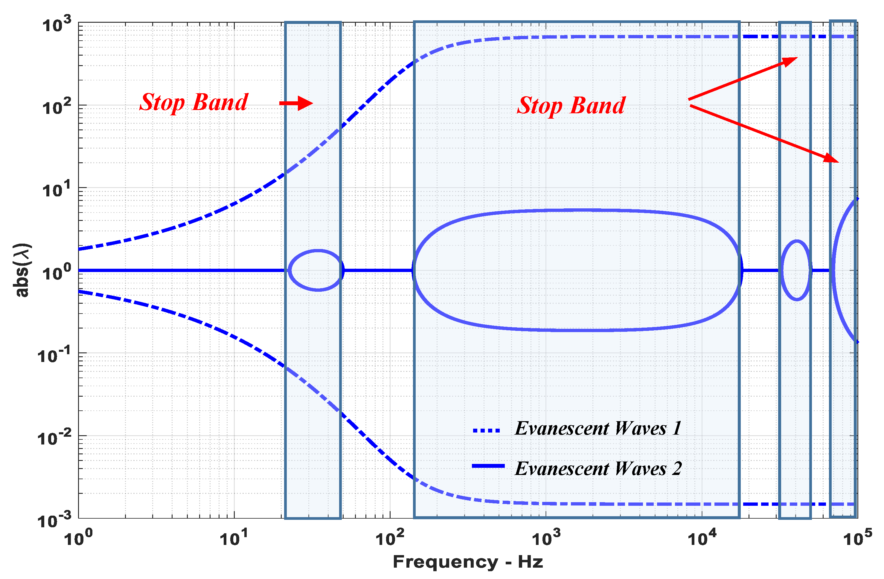
Figure 10 displays the absolute value of λ as a function of the excitation frequency when the flow velocity is zero. It indicates the presence of four stop bands when
. These bands occur between 20 and 50 Hz, 110 and 2 × 10
4 Hz, 3.5 × 10
4 and 6 × 10
4 Hz, and 7 × 10
4 and 1 × 10
5 Hz. The corresponding “
logarithmic decay” parameter α and “
phase shift” parameter β are displayed in
Figure 11. Similar results are obtained for other flow velocities.
7. Conclusions
This section summarizes the conclusions and the potential for future extensions of the present study.
In this paper, the concept of periodic marine risers is introduced and investigated in a comprehensive theoretical manner in order to establish the necessary design tools for the design and prediction of the performance characteristics of this new class of risers.
The proposed periodic risers are provided with an array of optimally placed and designed periodic inserts to reinforce the riser in order to enhance its elastic instability threshold to internal flows and also generate bandgap characteristics that can trap the vortex shedding excitations in order to mitigate their undesirable and detrimental effects. These features are envisioned to make the periodic risers essential technology for effective and reliable oil field production.
The effectiveness of the concept is investigated and demonstrated theoretically by modeling the dynamics of these risers using finite element analysis. The predictions of the developed finite element model are validated against the prediction of the commercial finite element package ANSYS. A close agreement is found between the two approaches.
The developed finite element model is then used to predict the instability threshold of the periodic risers to internal flows. The presented numerical example indicates that the periodic riser has nearly tripled the incipient of instability compared to conventional risers.
The developed model is also utilized to investigate, in great detail, the dispersion and bandgap and mechanical filtering characteristics of the periodic risers using the Bloch theory of wave propagation and the transfer matrix approach.
The obtained results indicate the presence of multiple stop bands over the operating frequency spectrum of the periodic riser that can be effectively tuned both in terms of location and spectral width in order to trap a wide range of vortex shedding frequencies to enable the mitigation of their adverse effects.
Comparisons are established between the performance characteristics of these periodic risers and conventional risers to demonstrate the merits and limitations of the proposed concept.
Extensive effort is now ongoing to validate the presented theoretical study experimentally and to demonstrate the merits and capabilities of the proposed periodic risers for a wide range of design parameters and operating conditions.
Further efforts are needed to investigate the effect of the shape of the inserts on the bandgap characteristics and address other important modes of operation of the risers such as controlling their recoil response. Further investigation is necessary to account for the effect of the stepped inserts on the flow and vortex shedding from the periodic riser. Such investigation should be guided by the wealth of research on dual stepped cylinders such as that reported by Ji et al. [
19].
