Article

Vibration Characteristics of Flexible Steel Plate on Proposed Magnetic Levitation System Using Gravity

1
Department of Electrical Engineering, Fukuoka Institute of Technology, Fukuoka 811-0295, Japan
2
Course of Mechanical Engineering, Tokai University, Hiratsuka 259-1292, Japan
3
Course of Science and Technology, Tokai University, Hiratsuka 259-1292, Japan
4
Department of Mechanical Engineering, Hokkaido University of Science, Sapporo 066-8585, Japan
5
Department of Mechanical Engineering, Tokyo University of Technology, Hachioji 192-0982, Japan
6
Department of Mechanical Systems Engineering, Tokai University, Hiratsuka 259-1292, Japan
*
Author to whom correspondence should be addressed.
Vibration 2022, 5(4), 936-945; https://doi.org/10.3390/vibration5040054
Submission received: 5 September 2022 / Revised: 4 December 2022 / Accepted: 15 December 2022 / Published: 18 December 2022

Abstract

:
Flexible steel plates are generally transported by rollers; however, the contact between the rollers and the steel plate degrades the surface quality of the plate. To solve this problem, noncontact transportation of steel plates using electromagnetic force has been proposed. However, ultrathin flexible steel plates can easily fall owing to deflection. A magnetic levitation system using electromagnets installed in the horizontal direction has also been proposed to improve the levitation performance of a conventional system. However, it is difficult to control vibrations with such a system because flexible steel plates are elastically deformed into complex shapes by gravity. Therefore, an electromagnetic levitation system was proposed, wherein electromagnets were installed near the edge of the steel plate such that it could be controlled with noncontact grip, such as by allowing one side of the steel plate to hang. This system is expected to improve levitation stability because the moment of inertia increases with vertical levitation and simplifies the control system. In addition, this system actively uses gravity acting on a steel plate to decrease its deflection. The use of gravity to suppress deflection is novel. In this study, the feasibility of magnetic levitation using the proposed system was investigated using magnetic field analysis. Its usefulness was investigated experimentally using a constructed magnetic levitation system. In addition, it was found that a magnetic levitation system that maintains the standing position generates a peculiar vibration.

1. Introduction

Thin steel plates are widely used in automobile manufacturing and in electrical appliances. They are transported using rollers in production lines. The friction between the rollers and the thin steel plate deteriorates their surface quality. Magnetic levitation technology has been proposed to solve this problem [1,2,3]. Electromagnetic suspension (EMS) technology using an electromagnet has been used for the magnetic levitation of steel. Previous studies used EMS technology to levitate rigid-body steel plates [4] and steel balls [5,6,7]. However, in the case of a thin steel plate, advanced magnetic levitation control is required by considering modeling error and disturbance. Therefore, noncontact gripping and transfer of thin steel plates have been studied [8,9,10,11,12,13,14]. Guney et al. [15] and Choi et al. [16] proposed magnetic levitation and transportation systems using the theory of linear induction motors. Matsumoto et al. [17] proposed a system in which a unit for magnetic levitation is transported using a linear induction motor.
In these studies, the electromagnets for levitation control were located on the upper side of the thin steel plate. The steel plate was levitated by balancing the attractive force of the electromagnet with the weight of the steel plate. Most studies on magnetic levitation technology have focused on steel plates with thicknesses of 1 mm or more. In recent years, the use of high-strength and ultrathin flexible steel plates has been encouraged to reduce environmental impact and increase efficiency. Steel plates with a thickness of approximately 1.0 mm or less are referred to as flexible steel plates, and they have relatively low bending stiffness. Therefore, when levitated using conventional technology, deflection occurs in the flexible steel plates in the area where electromagnetic forces do not reach, resulting in complicated vibrations and making it difficult to stabilize levitation.
Therefore, research has been conducted on magnetic levitation systems for flexible steel plates [18,19,20]. In particular, Takada et al. [21] levitated steel plates of several thicknesses using pole placement, and Suzuki et al. [22] improved the levitating stability of a steel plate by controlling and considering its twisting mode. Moreover, sliding mode control [23] and disturbance cancellation control [24], considering the modeling error caused by deflection and disturbance caused by transportation, were proposed. On the other hand, in our previous study, we found that suppression of deflection improves levitation stability. Based on these results, our research group successfully improved the levitation stability of flexible steel plates by installing electromagnets in the horizontal direction and applying tension along the edge of the steel plate [25]. A method for suppressing deflection by placing permanent magnets within the area where the attractive force from the electromagnets is not reached has also been proposed [26]. These methods have revealed that stable levitation is possible for steel plates that are less than 0.3 mm [27,28,29,30,31]. Levitation can be achieved with flexible steel plates that are less than 0.3 mm thick, for which demand has been increasing in recent years, although more stable levitation is required for practical applications.
The magnetic levitation system in these studies stabilized the levitating plate. As control systems or devices for levitation that suppress deflection are complicated, simple methods for deflection suppression have been explored. The authors proposed a new magnetic levitation system in which a flexible steel plate is oriented to ensure that its moment of inertia is reduced during levitation. The plate deflection is suppressed by the gravity of the plate. In this study, a magnetic levitation system was constructed to demonstrate the effectiveness of the proposed system. Next, the levitation characteristics of the proposed magnetic levitation system were investigated analytically. Furthermore, the levitation characteristics when optimal control was applied were investigated experimentally. Thus, this study aimed to investigate the possibility of levitation using the proposed method and demonstrate the effect of levitation using the weight coefficient of optimal control. The novelty of this paper is the use of gravity to suppress the deflection of flexible steel plates. The goals of this paper are stable magnetic levitation by the proposed method and to construct a control system with reduced vibration.

2. Proposed Magnetic Levitation System for Flexible Steel Plate

Conventional magnetic levitation systems levitate flexible steel plates such that the plate thickness direction is vertical [18,19,27,28]. In this plate direction, deflection occurs in the area where the attractive force of the electromagnets is not reached, and the levitation stability deteriorates. In addition, the number of electromagnets must be increased to suppress the deflection, thereby complicating the system. This paper proposes a magnetic levitation system that levitates a steel plate horizontally in the direction of its thickness, as shown in Figure 1. The magnetic levitation system holds the flexible steel plate in such a direction that the moment of inertia decreases relative to the gravitational force applied to the flexible steel plate. Therefore, deflection is suppressed by the gravitational force applied to the steel plates, which is expected to improve the levitation stability of the magnetic levitation system.
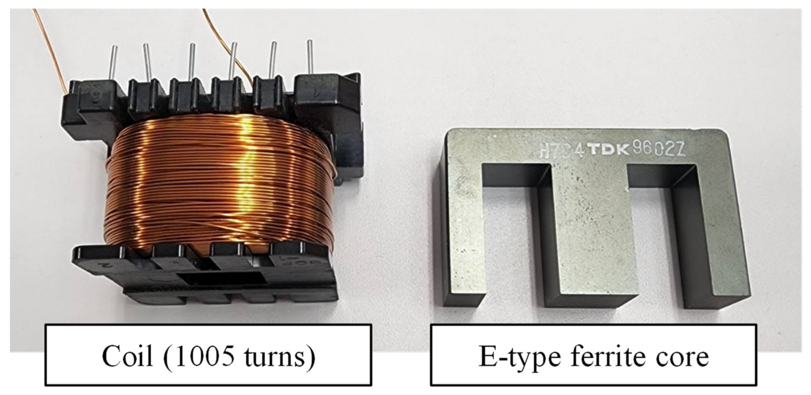
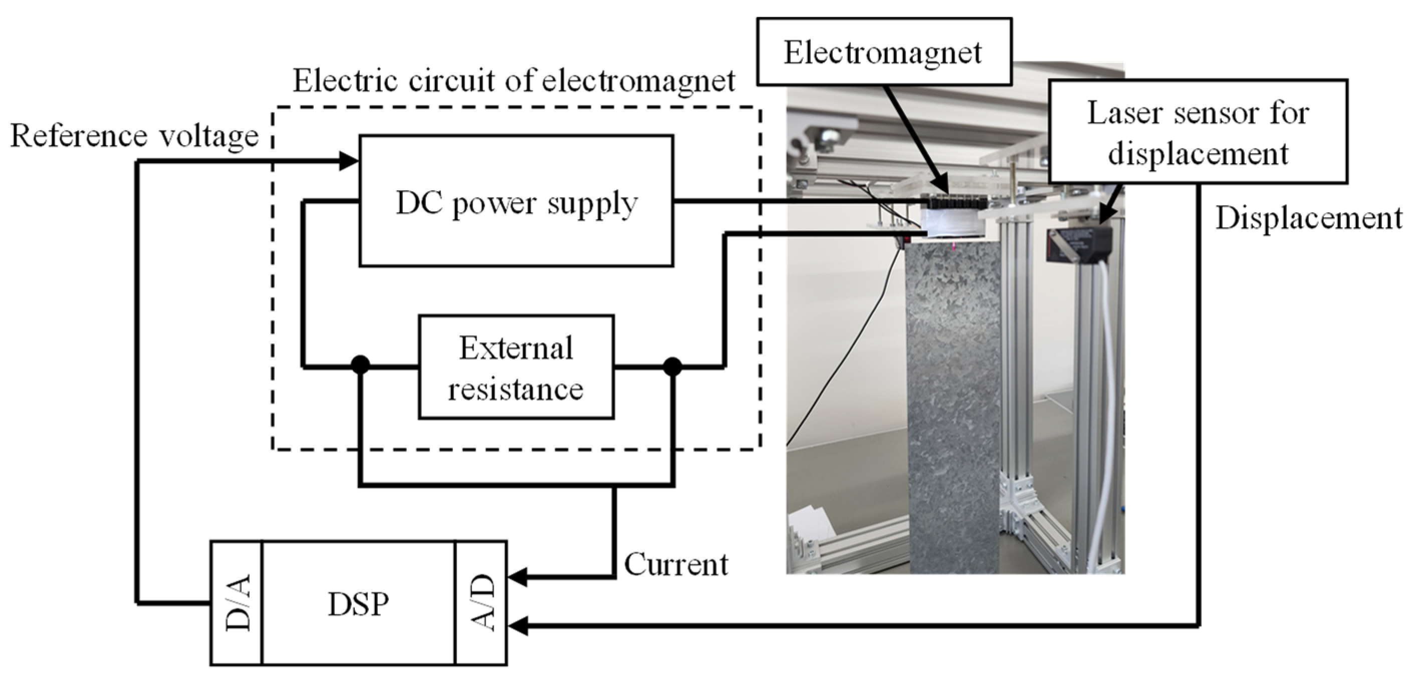
In this magnetic levitation system, a single electromagnet is positioned above a flexible steel plate to generate an attractive levitation force. The electromagnet core was an E-type ferrite, as shown in Figure 2. The electromagnetic coil wire had a diameter of 0.5 mm and consisted of 1005 turns. The object to be levitated was a rectangular galvanized steel plate (material SS400) that was 400 mm long, 100 mm wide, and 0.24 mm thick. Figure 3 shows the schematic of the magnetic levitation system. In this system, state feedback control was applied using the displacement and velocity of the flexible steel plate. In addition, displacement was measured in the horizontal direction using a laser sensor manufactured by KEYENCE (the displacement was measured as the amount of cutoff at the belt-shaped laser beam). The terminal voltage of the external resistance installed in the electromagnetic circuit was measured to determine the current flowing in the electromagnet. The two observed values of voltage and displacement were input to a digital signal processor (DSP) via an A/D converter. The DSP calculates the control voltage applied to the electromagnetic coils. The command value of the control voltage was input to the DC power supply via a D/A converter, and the voltage was applied to the electric circuit, including the coil of the electromagnet.

3. Attractive Force of Proposed Magnetic Levitation System

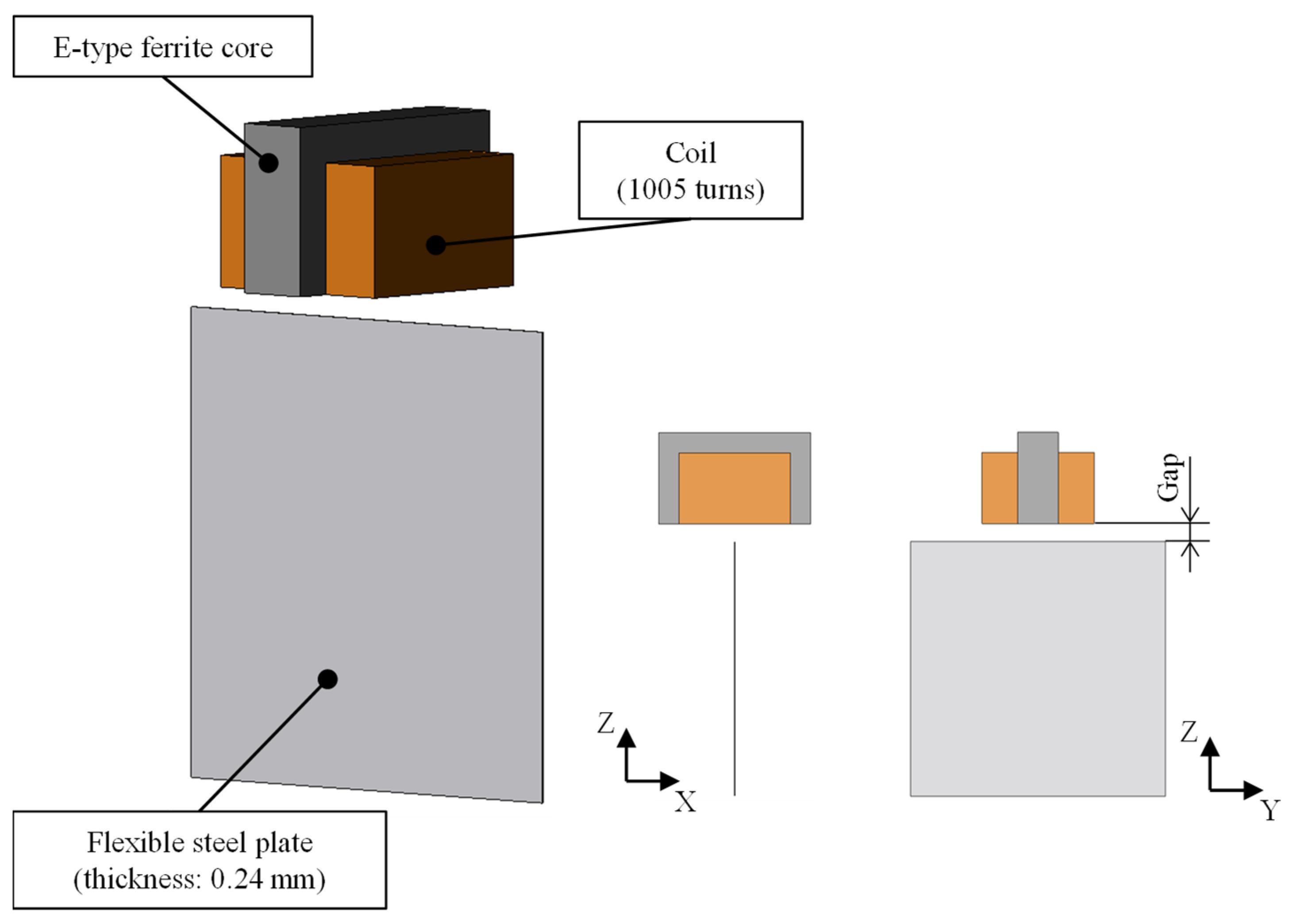
In magnetic levitation, contactless holding is achieved by generating an attractive force that equilibrates the weight of a levitated object. The flexible steel plate to be levitated in this study was extremely thin with electromagnets installed near the edge of the plate. Therefore, it is necessary to investigate whether electromagnets can generate sufficient attractive force. In this study, an electromagnetic field analysis using the finite element method was conducted. The electromagnetic field analysis software JMAG (manufactured by JSOL, ver. 21.0) was used in the analysis and the attractive force applied to a flexible steel plate during levitation was investigated. Figure 4 shows the three-dimensional model used in the analysis. In this analysis, the flexible steel plate was SS400, and the electromagnet core was ferrite (PC40), both of which exhibited nonlinear B–H curve characteristics with reference to an actual magnetic levitation system. Copper wire coils (specific permeability 1, resistivity 1.673 × 10⁻⁸ Ωm) were used for the electromagnets, with the number of turns set to 1005. The air region was a cube with a side of 500 mm centered on the electromagnet core, and the number of elements in the model was 104,420. In this analysis, we varied the gap between the flexible steel plates, the electromagnet, and the current flowing through the coil of the electromagnet. Furthermore, we investigated the relationship between the gap and the current when a flexible steel plate was levitated.
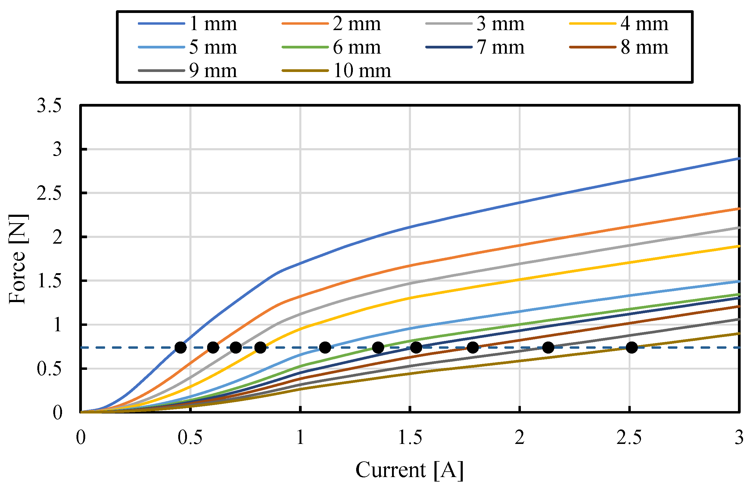
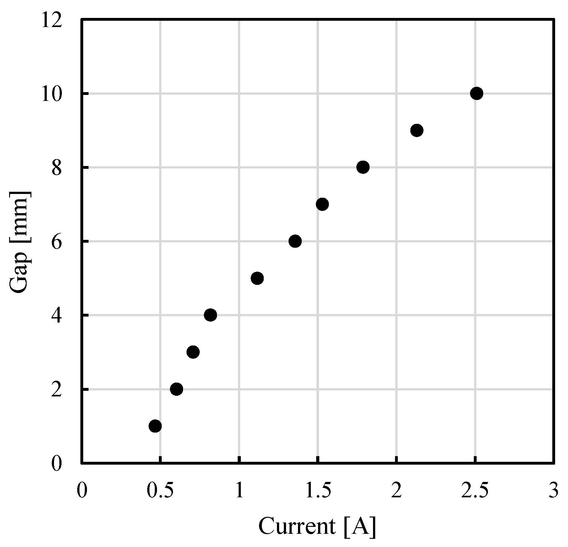
Figure 5 shows the relationship between the current and attractive forces. Each gap is represented by a solid line with a different color. The dashed line shows the weight of the flexible steel plate. The dots indicate the intersections of dashed and solid lines. These dots indicate the state in which the flexible steel plate was levitated. Based on the dots in Figure 5, Figure 6 shows the relationship between the current and gap when the flexible steel plate can levitate. The gap between the flexible steel plate and electromagnet increased as the current flowing through the electromagnet increased, indicating that the levitation position of the flexible steel plate decreased. In addition, the current can flow up to 2 A in this electromagnet, considering the heat generation. Therefore, although the analysis was static, the system generated a support force that enabled the levitation. The control system for magnetic levitation will be developed in the next section, and the displacement and current at an equilibrium point will be investigated based on this relationship.

4. Control System for Levitating Flexible Steel Plate

The results in Section 3 reveal that the proposed system can be levitated. However, the vibration state of a flexible steel plate during levitation must be investigated experimentally. Therefore, a control system for magnetic levitation of flexible steel plates was developed in this study. The flexible steel plate generates elastic vibration in the horizontal direction but can be considered a rigid body in motion in the vertical plane [31]. An equilibrium point exists where the steel plate is maintained at a certain distance from the electromagnet by applying the same static attractive force from the electromagnet. The displacement of the steel plate from the equilibrium point is z, and the equations of state are as follows [25,26]:
x ˙ = A x + B v
x = [ z z ˙ i ] T
A = [ 0 1 0 2 F z m Z 0 0 2 F z m I 0 L eff I L Z 0 2 R 2 L ]
B = [ 0 0 1 2 L ] T
where Fz is the magnetic force of the coupled magnets in the equilibrium state [N], Z0 is the gap between the metal foil and electromagnet in the equilibrium state [m], I is the current of the coupled magnets in the equilibrium state [A], i is the dynamic current of the coupled magnets [A], L is the inductance of one magnet coil in the equilibrium state [H], R is the resistance of the coupled magnet coils [Ω], v is the dynamic voltage of the coupled magnets [V], and Leff/X0 is the effective inductance of one magnet coil [H].
As in previous studies, the feedback gains in this control system were calculated using the optimal control method [32]. The feedback gain was used to calculate the control voltage v using Equation (2).
v = f 1 z f 2 z ˙ f 3 i
where f1 is the feedback gain for displacement z, f2 is the feedback gain for velocity z ˙ , and f3 is the feedback gain for the control current i.

5. Vibration Characteristics of a Levitating Flexible Steel Plate

In Section 3, it was determined that the proposed system can realize magnetic levitation using analysis. However, because Section 3 uses static analysis, it is necessary to experimentally investigate the feasibility of the system. Therefore, as a basic study, magnetic levitation experiments were conducted using the control model described in Section 4. In this experiment, the steady-state current was set to 1.3 A, and various parameters were calculated using the electromagnetic field analysis. Optimal control was used to determine feedback gains. In optimal control, the control characteristics change significantly depending on the number of weight coefficient sets. Larger weight coefficients in optimal control improve the convergence. However, in a general control system, there is an upper limit to the number of weight coefficients owing to voltage limitations. Therefore, to improve the levitation stability of the proposed system, it is necessary to clarify the effect of weight coefficients on levitation stability. Therefore, in this experiment, several combinations of weight coefficients were used to investigate the effect of the control characteristics on the levitation performance. Table 1 lists the weight coefficients used in this experiment. During levitation, the control started with the steel plate supported by hand near the equilibrium point, and the hand was released to start levitation after confirming the generation of an attractive force.
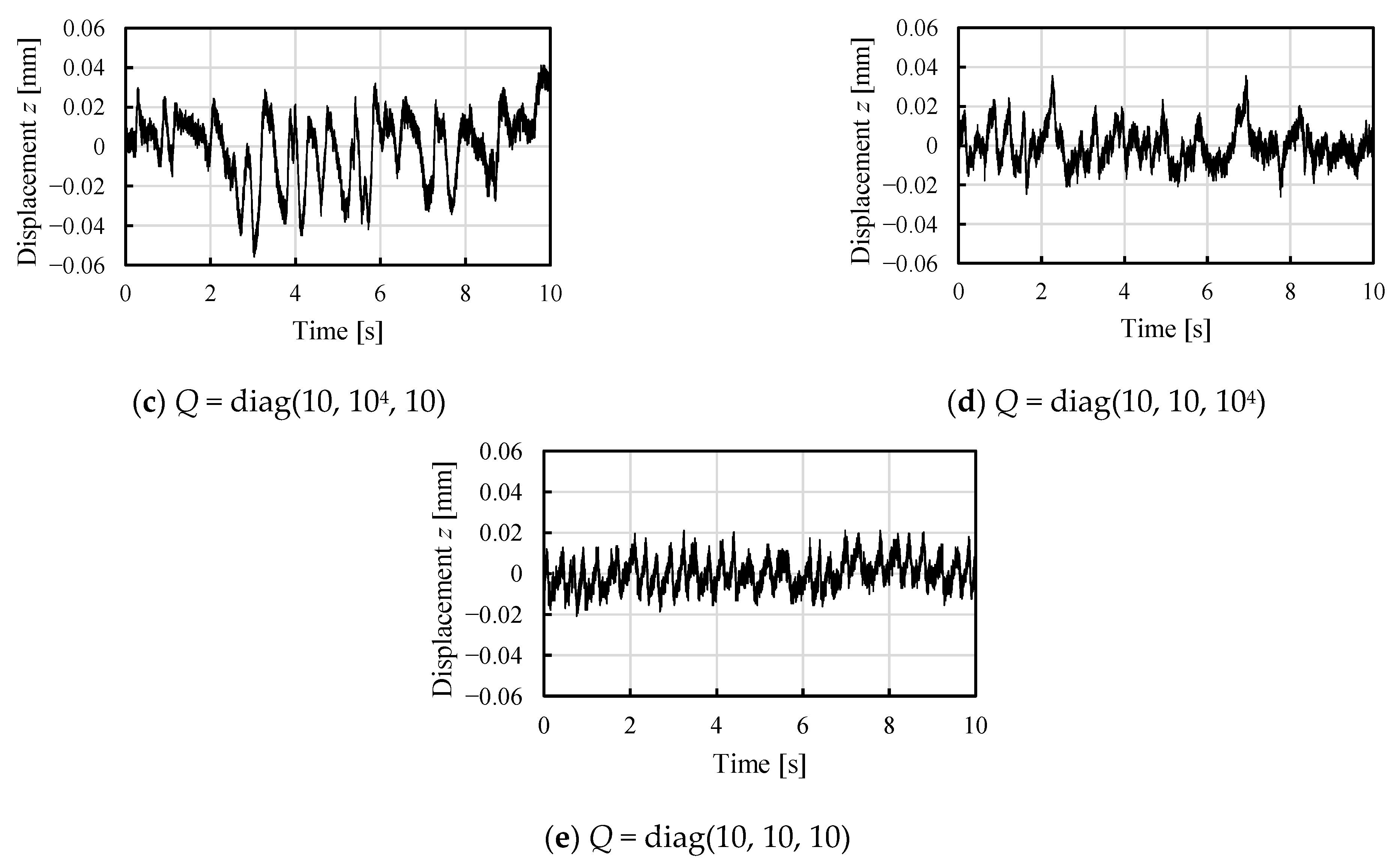
First, Table 2 shows the gap when the steady-state current is set to 1.3 A. Table 2 shows the “analytical values” obtained from the electromagnetic field analysis in Chapter 3 and the “experimental values” obtained from experiments using the magnetic levitation system. The analytical and experimental values were almost identical, indicating that the electromagnetic field analysis results were valid. Figure 7 shows the displacement of the flexible steel plate in the vertical (Z-axis) direction during the magnetic levitation. The equilibrium point was set to 0 mm in time history. Under all the conditions, the flexible steel plate was stably levitated without divergence. When the weighting factors of the velocity and current were set to greater than 104, levitation could not be achieved. Therefore, it was demonstrated that the system constructed based on the results of the electromagnetic field analysis was capable of levitation. However, the displacement of the flexible steel plate is vibratory. This may be due to the feedback of the velocity and displacement of the flexible steel plate, which is apparently a one-degree-of-freedom system consisting of a spring and damper. Figure 7 shows that the displacement amplitude depends on the combination of the weighting factors. The displacement amplitude deteriorates levitation stability. To evaluate the displacement amplitude, Table 3 lists the standard deviations of the displacement for each weighting coefficient pattern. The standard deviation of the displacement indicates the root-mean-square (RMS) displacement at the equilibrium point [32]. When the weighting factors of the displacement, velocity, and current weights were each set to 104, the standard deviation was larger, and the levitation stability degraded. In contrast, increasing the displacement weight to 109 improved the levitation stability. Therefore, it was determined that stable levitation could be achieved by setting the displacement weight coefficient to be relatively larger than the other weight coefficients.

6. Conclusions

This study proposes a magnetic levitation method that reduces the moment of inertia of flexible steel plates and investigates its levitation feasibility and controller. First, we adopted electromagnetic field analysis using the finite element method, where an electromagnet can exert sufficient attractive force to levitate a flexible steel plate. Next, a magnetic levitation system was constructed and the possibility of levitation was experimentally investigated. It was then found that the proposed magnetic levitation system could achieve stable levitation. Furthermore, we revealed that the levitation stability can be improved by increasing the displacement weight coefficient when the optimal control method is employed. These results indicate that the novel gravity-based deflection suppression was able to achieve stable magnetic levitation.
The results obtained in this study clearly reveal that the proposed magnetic levitation system is feasible and has the potential to outperform other magnetic levitation systems. Future studies should consider complex issues, such as the levitation of flexible steel plates of different thicknesses and control systems in the presence of disturbances, to further improve stability.

Author Contributions

Conceptualization, A.E., T.N. and H.K.; methodology, J.K., K.O. and T.N.; software, J.K., D.U., K.I. and T.K.; validation, A.E., R.I., K.I. and T.K.; formal analysis, J.K., D.U., K.O. and T.N.; investigation, R.I., J.K. and D.U.; resources, A.E. and R.I.; data curation, A.E., R.I. and K.O.; writing—original draft preparation, A.E. and R.I.; writing—review and editing, A.E., K.I., T.K., T.N. and H.K.; visualization, A.E., R.I., K.I. and T.K.; supervision, K.I., T.K., T.N. and H.K.; project administration, A.E., T.N. and H.K.; funding acquisition, A.E. All authors have read and agreed to the published version of the manuscript.

Funding

This work was supported by JSPS KAKENHI (grant number JP22K14228).

Data Availability Statement

Not applicable.

Conflicts of Interest

The authors declare no conflict of interest.

References

  1. Murakami, I.; Zhao, Y.; Tashiro, T. Stabilization of a Magnetic Repulsive Levitation Flywheel System Using a High-Efficiency Superconducting Magnetic Bearing. Actuators 2022, 11, 180. [Google Scholar] [CrossRef]
  2. Stettinger, G.; Benedikt, M.; Horn, M.; Zehetner, J.; Giebenhain, C. Control of a magnetic levitation system with communication imperfections: A model-based coupling approach. Control Eng. Pract. 2017, 58, 161. [Google Scholar] [CrossRef]
  3. Xu, F.; Zhang, K.; Xu, X. Development of Magnetically Levitated Rotary Table for Repetitive Trajectory Tracking. Sensors 2022, 22, 4270. [Google Scholar] [CrossRef]
  4. Dalwadi, N.; Deb, D.; Muyeen, S.M. A Reference Model Assisted Adaptive Control Structure for Maglev Transportation System. Electronics 2021, 10, 332. [Google Scholar] [CrossRef]
  5. Ismail, L.S.; Lupu, C.; Alshareefi, H. Design of Adaptive-RST Controller for Nonlinear Magnetic Levitation System Using Multiple Zone-Model Approach in Real-Time Experimentation. Appl. Syst. Innov. 2022, 5, 93. [Google Scholar] [CrossRef]
  6. Belmonte, L.M.; Segura, E.; Fernández-Caballero, A.; Somolinos, J.A.; Morales, R. Generalised Proportional Integral Control for Magnetic Levitation Systems Using a Tangent Linearisation Approach. Mathematics 2021, 9, 1424. [Google Scholar] [CrossRef]
  7. Gopi, R.S.; Srinivasan, S.; Panneerselvam, K.; Teekaraman, Y.; Kuppusamy, R.; Urooj, S. Enhanced Model Reference Adaptive Control Scheme for Tracking Control of Magnetic Levitation System. Energies 2021, 14, 1455. [Google Scholar] [CrossRef]
  8. Hayashiya, H.; Ohsaki, H.; Masada, E. A combined lift and propulsion system of a steel plate by transverse flux linear induction motors. IEEE Trans. Magn. 1999, 35, 4019. [Google Scholar] [CrossRef]
  9. Ohji, T.; Shinkai, T.; Amei, K.; Sakui, M. Application of Lorentz force to a magnetic levitation system for a non-magnetic thin plate. J. Mater. Process. Technol. 2007, 181, 40. [Google Scholar] [CrossRef]
  10. Odajima, Y.; Takada, Y.; Oikawa, I.; Nakagawa, T. Construction and levitation guidance experiment of magnetic levitation system without gap sensors using inductance model of thin steel plates. Electr. Eng. Jpn. 2019, 206, 32. [Google Scholar] [CrossRef]
  11. Arita, Y.; Ota, K.; Oikawa, I.; Nakagawa, T. A proposal of magnetic levitation system without using sideslip-sensors and actuators in guidance control. In Proceedings of the 20th International Conference on Electrical Machines and Systems, Sydney, Australia, 11–14 August 2017; Volume 20, p. 1. [Google Scholar] [CrossRef]
  12. Liu, C.T.; Yang, Y.Y.; Lin, S.Y. On-line realizations of dynamic gap detection and control for levitated industrial steel plate conveyance system. In Proceedings of the IEEE Industry Applications Society Annual Meeting, Las Vegas, NV, USA, 7–11 October 2012. [Google Scholar] [CrossRef]
  13. Liu, C.T.; Yang, Y.Y.; Lin, S.Y. Development of an Automatic Online Gap-Detection Scheme for Levitated Industrial Steel-Plate Conveyance System. IEEE Trans. Ind. Appl. 2008, 44, 517. [Google Scholar] [CrossRef]
  14. Kundu, J.; Sengupta, M. Design, analysis, fabrication, control and comparative study of two different-shaped plate levitation prototypes. Sādhanā 2020, 45, 53. [Google Scholar] [CrossRef]
  15. Guney, O.F.; Bozkurt, A.F.; Erkan, K. Centralized gap clearance control for maglev based steel-plate conveyance system. Adv. Electr. Comput. Eng. 2017, 17, 101. [Google Scholar] [CrossRef]
  16. Choi, J.S.; Baek, Y.S. Magnetically-Levitated Steel-Plate Conveyance System Using Electromagnets and a Linear Induction Motor. IEEE Trans. Magn. 2008, 44, 4171. [Google Scholar] [CrossRef]
  17. Matsumoto, S.; Arai, Y.; Nakagawa, T. Noncontact Levitation and Conveyance Characteristics of a Very Thin Steel Plate Magnetically Levitated by a LIM-Driven Cart. IEEE Trans. Magn. 2014, 50, 8600304. [Google Scholar] [CrossRef]
  18. Namerikawa, T.; Mizutani, D.; Robust, H. DIA Control of Levitated Steel Plates. IEEJ Trans. Ind. Appl. 2006, 126, 1319. [Google Scholar] [CrossRef] [Green Version]
  19. Hasegawa, S.; Oshinoya, Y.; Ishibashi, K. Consideration on Elastic Vibration Control of a Magnetically Levitated Thin Steel Plate Using Sliding Mode Control. JSME Int. J. Ser. C Mech. Syst. Mach. Elem. Manuf. 2006, 49, 983. [Google Scholar] [CrossRef] [Green Version]
  20. Ogawa, K.; Miyazaki, R.; Uchida, Y.; Kobayashi, I.; Kuroda, J.; Uchino, D.; Ikeda, K.; Kato, T.; Endo, A.; Narita, T.; et al. Experimental Consideration on Suppression Effect of Elastic Vibration in Electromagnetic Levitation System for Flexible Thin Steel Plate with Curvature. Vibration 2022, 5, 817–828. [Google Scholar] [CrossRef]
  21. Takada, Y.; Kimura, T.; Nakagawa, T. Influence of Inductance Properties on a Magnetic Levitation for Thin-Steel Plates. IEEE Trans. Magn. 2017, 53, 2500705. [Google Scholar] [CrossRef]
  22. Suzuki, O.; Nagashima, D.; Nishimura, K.; Nakagawa, T. Magnetic Levitation Control by Considering the Twisting Mode of a 0.18 mm Thick Steel Plate. IEEE Trans. Magn. 2015, 51, 8600304. [Google Scholar] [CrossRef]
  23. Ogawa, K.; Funada, K.; Narita, T.; Kato, H. Vibration suppression effect in an electromagnetic levitation system for flexible steel plate: Experimental consideration on levitation performance using sliding mode control. In Proceedings of the International Conference on Motion and Vibration Control, Toki Messe, Niigata, 8–11 September 2020; p. 10112. [Google Scholar] [CrossRef]
  24. Ogawa, K.; Tada, M.; Narita, T.; Kato, H. Electromagnetic Levitation Control for Bending Flexible Steel Plate: Experimental Consideration on Disturbance Cancellation Control. Actuators 2018, 7, 43. [Google Scholar] [CrossRef] [Green Version]
  25. Ito, Y.; Oda, Y.; Kato, T.; Liu, X.; Endo, A.; Ikeda, K.; Narita, T.; Kato, H. Basic study on effect of transport acceleration in electromagnetic levitation system for thin steel plate. Int. J. Appl. Electromagn. Mech. 2020, 64, 597. [Google Scholar] [CrossRef]
  26. Ito, Y.; Oda, Y.; Narita, T.; Kato, H. Effect of Optimal Placement of Permanent Magnets on the Electromagnetic Force in the Horizontal Direction. Actuators 2018, 7, 54. [Google Scholar] [CrossRef] [Green Version]
  27. Narita, T.; Oda, Y.; Ito, Y.; Kato, H. A basic study on levitation characteristics of metal foil by edge-supported electromagnetic levitation system. Int. J. Appl. Electromagn. Mech. 2020, 64, 1191. [Google Scholar] [CrossRef]
  28. Narita, T.; Kida, M.; Suzuki, T.; Kato, H. Study on Electromagnetic Levitation System for Ultrathin Flexible Steel Plate Using Magnetic Field from Horizontal Direction. J. Magn. Soc. Jpn. 2017, 41, 14. [Google Scholar] [CrossRef] [Green Version]
  29. Narita, T.; Oda, Y.; Ito, Y.; Okuno, K.; Kato, H. Positioning Control for Flexible Steel Plate Using Facing Electromagnetic Actuator: Fundamental Consideration on Support Characteristic of Electromagnetic Actuator. In Proceedings of the 16th International Conference on New Actuators, Bremen, Germany, 25–27 June 2018; p. 344. [Google Scholar]
  30. Oda, Y.; Ito, Y.; Okuno, K.; Kida, M.; Suzuki, T.; Narita, T.; Kato, H.; Moriyama, H. A Study on Edge Supported Electromagnetic Levitation System: Fundamental Consideration on Levitation Performance of Thin Steel Plate. In Proceedings of the International Power Electronics Conference, Niigata, Japan, 20–24 May 2018; p. 2324. [Google Scholar] [CrossRef]
  31. Oda, Y.; Kida, M.; Suzuki, T.; Narita, T.; Kato, H.; Moriyama, H. Basic study on edge supported electromagnetic levitation system for flexible steel plate. Int. J. Appl. Electromagn. Mech. 2019, 59, 985. [Google Scholar] [CrossRef]
  32. Oda, Y.; Ito, Y.; Okuno, K.; Kida, M.; Suzuki, T.; Endo, A.; Narita, T.; Kato, H.; Moriyama, H. Evaluation on Edge-supported Magnetic Levitation Apparatus for Thin Steel Plates. J. Magn. Soc. Jpn. 2019, 43, 11. [Google Scholar] [CrossRef]
Figure 1. Proposed magnetic levitation system.
Vibration 05 00054 g001
Figure 2. Coil and E-type ferrite core for the electromagnet. A ferrite core was inserted into the coil.
Vibration 05 00054 g002
Figure 3. Schematic of this magnetic levitation system.
Vibration 05 00054 g003
Figure 4. Model for magnetic field analysis.
Vibration 05 00054 g004
Figure 5. Relationship between the current of an electromagnet and the force of the steel plate in each gap. The dashed line shows the weight of the steel plate. The dots (·) show intersection points between the solid and dashed lines, and show possible conditions for levitation of the steel plate.
Vibration 05 00054 g005
Figure 6. Relationship between the gap and current. Flexible steel plates levitate by following this relationship in the proposed system.
Vibration 05 00054 g006
Figure 7. Time histories of the vertical displacement of the steel plate.
Vibration 05 00054 g007aVibration 05 00054 g007b
Table 1. Weighting factors for the experiments.
No.Weighting Factor Q = Diag(q1, q2, q3)
(q1: For Displacement z, q2: For Velocity dz/dt, q3: For Current i)
(a)Q = diag(109, 10, 10)
(b)Q = diag(104, 10, 10)
(c)Q = diag(10, 104, 10)
(d)Q = diag(10, 10, 104)
(e)Q = diag(10, 10, 10)
Table 2. Gaps between the surface electromagnet and edge of the flexible steel plate.
TypeGap [mm]
Analytical5.94
Experimental5.75
Table 3. Standard deviations of displacement of each weighting coefficient pattern.
Weighting Coefficient QStandard Deviations of Displacement z [mm]
(a)Q = diag(109, 10, 10)0.0033
(b)Q = diag(104, 10, 10)0.0117
(c)Q = diag(10, 104, 10)0.0255
(d)Q = diag(10, 10, 104)0.0129
(e)Q = diag(10, 10, 10)0.0083
Publisher’s Note: MDPI stays neutral with regard to jurisdictional claims in published maps and institutional affiliations.